1
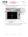
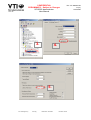
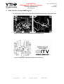
CONFIDENTIAL
PRELIMINARY – Subject to Changes
SCA3000 demonstrator
User Manual
VTI / JL
Doc. Nr. 8259300.05
1 (17)
13.03.2006
SCA3000 Demonstrator User Manual
VTI Technologies Oy
VAT Reg.
Business ID 0707944-4
Domicile Vantaa
CONFIDENTIAL
PRELIMINARY – Subject to Changes
SCA3000 demonstrator
User Manual
VTI / JL
Doc. Nr. 8259300.05
2 (17)
13.03.2006
Table of Contents
1
INTRODUCTION ............................................................................................................................................................. 3
2
QUICK START ................................................................................................................................................................. 3
3
HARDWARE ..................................................................................................................................................................... 4
4
GUI SOFTWARE.............................................................................................................................................................. 5
4.1
4.2
RESETTING GUI AND µC .............................................................................................................................................. 9
UNINSTALLING THE GUI AND USB DRIVER ................................................................................................................. 9
5
ADVANCED DATA LOGGING.................................................................................................................................... 10
6
SCA3000 CURRENT CONSUMPTION MEASUREMENT....................................................................................... 11
7
PROBLEMS?................................................................................................................................................................... 12
8
USB INTERFACE BOARD SCHEMATICS ................................................................................................................ 14
9
USB INTERFACE BOARD PWB LAYOUT................................................................................................................ 17
Document Change Control Page
Version
Date
Change Description
Author
0.01
0.02
02.12.2005
20.01.2006
JL
JL
0.03
0.04
01.02.2006
14.02.2006
0.05
13.03.2006
Initial draft
New GUI revision (0.16), instructions for current consumption measurement, Advanced
data logging
Equation for current consumption calculation corrected
New GUI revision (0.16.2) supports SCA3000 component versions:
- SCA3000-D01 v0.3
- SCA3000-E01 v0.3
- SCA3000-D01 v0.1 (old)
New GUI revision (0.16.2) supports all SCA3000 component versions (also I2C bus)
VTI Technologies Oy
VAT Reg.
Business ID 0707944-4
Domicile Vantaa
JL
JL
JL
CONFIDENTIAL
PRELIMINARY – Subject to Changes
SCA3000 demonstrator
User Manual
VTI / JL
Doc. Nr. 8259300.05
3 (17)
13.03.2006
1 Introduction
SCA3000 demo demonstrates the SCA3000 component functionality and the component key
properties. This document describes how to install the required software and how to use the
SCA3000 demo board and Graphical User Interface (GUI) software revision 0.16.4.
SCA3000 demo consists of:
• SCA3000 sensor soldered on chip carrier PWB
• USB interface card
• USB cable
• GUI software running on PC
SCA3000 demo runs on Windows XP and 2000, it requires USB connection for data transfer.
Demo is powered from USB port.
2 Quick start
Please follow the steps below:
1. Insert CD-ROM
2. Setup the hardware
- Connect the hardware to PC's USB port
3. Install the USB driver, after the PC has found the device
- When the PC detects the new USB device, do not let Windows to detect the driver,
address the USB driver from folder:
"CD-ROM\SCA3000 demo - Virtual Com Port Drivers\”
- NOTICE, if you have already installed the SCP1000 demo to your computer,
please set the latency timer to 5 ms (more detailed instructions on section 7)
4. Install the GUI software
- Install the GUI software by running the “setup.exe" from folder:
CD-ROM\SCA3000 demo - ver 0.16 - Installer
- Do not change the installation destination
5. Start the GUI software
- From Start → Programs → SCA3000-DEMO
Notice that the demo should be connected to PC before the GUI software is started. Exit the GUI
software before unplugging the demo (demo uses virtual serial port driver, so it can not be found as
a USB device).
VTI Technologies Oy
VAT Reg.
Business ID 0707944-4
Domicile Vantaa
CONFIDENTIAL
PRELIMINARY – Subject to Changes
SCA3000 demonstrator
User Manual
VTI / JL
Doc. Nr. 8259300.05
4 (17)
13.03.2006
3 Hardware
The SCA3000 demo USB interface board (black) and SCA3000 PWB (red) are shown in Figure 1.
The interface card converts the USB interface to SPI or I2C interface. SCA3000 sensor is soldered
on PWB which is connected to interface board.
SCA3000 sensor,
see component type and
version (v0.1 or v0.3)
Red led: demo powered
from USB
Demo reset
Test points for
SCA3000 sensor
Idd measurement
Green led: data transfer
Figure 1 SCA3000 demo USB interface board and SCA3000 PWB.
VTI Technologies Oy
VAT Reg.
Business ID 0707944-4
Domicile Vantaa
Doc. Nr. 8259300.05
5 (17)
13.03.2006
CONFIDENTIAL
PRELIMINARY – Subject to Changes
SCA3000 demonstrator
User Manual
VTI / JL
4 GUI software
SCA3000 demo is controlled via USB serial port by GUI software. The software must be installed
into location that is suggested during installation procedure.
Screen capture of the GUI is presented in Figure 2.
Pull down menu
for display mode
Pull down menu for
SCA3000 mode
Yellow: acceleration
register overflow, out
of measuring range
0.16.4
Red: Interrupt detected,
press to clear interrupt
Exit button
GUI software
revision number:
0.16.4
Figure 2 SCA3000 demo Graphical User Interface
The GUI software has three different display modes. The SCA3000 sensor can be set to:
- normal measurement mode,
- free fall mode and
- motion detector mode.
The interrupt detected due free fall or motion is indicated by led indicator and sound. Once interrupt
is detected, the interrupt has to be cleared by user by pressing the led (Figure 2).
The five different GUI displays and start up screens are presented below.
VTI Technologies Oy
VAT Reg.
Business ID 0707944-4
Domicile Vantaa
CONFIDENTIAL
PRELIMINARY – Subject to Changes
SCA3000 demonstrator
User Manual
VTI / JL
Doc. Nr. 8259300.05
6 (17)
13.03.2006
If more than one USB serial port devices
are detected, user must select USB
SERIAL PORT pop-up window the correct
port (Figure 3).
Figure 3 USB serial port selection pop-up window.
User needs to select correct product type
from PRODUCT SELECTION pop-up
window (Figure 4). SCA3000-D01 is
selected by default, product type can be
found from top SCA3000 component, see
Figure 1.
Figure 4 Product selection pop-up window.
SCROLL, continuously scrolling X, Y, Z
and resultant accelerations, see Figure 5.
Acceleration is presented in [g]. User can:
- change the acceleration scale
- freeze the scrolling image
- change the averaging factor
- set averaging OFF
- save acceleration data into file
- enable resultant scrolling
- detect which axis caused the
interruption in motion detection mode
(by clearing the interrupt)
Figure 5 Scroll display.
Resultant enable /
disable
VTI Technologies Oy
VAT Reg.
Business ID 0707944-4
In motion detection mode user
can select for operation where
sensor operation mode is
changed to measurement mode
after motion is detected.
Domicile Vantaa
CONFIDENTIAL
PRELIMINARY – Subject to Changes
SCA3000 demonstrator
User Manual
VTI / JL
Doc. Nr. 8259300.05
7 (17)
13.03.2006
BUBBLE LEVEL, two displays that show
tilt angle, see Figure 6. Angle calculation is
performed in GUI, not in SCA3000 sensor.
Figure 6 Bubble level display.
3D, 3 dimensional display with projections
of each axis acceleration, see Figure 7.
Min / max of resultant
acceleration
Figure 7 3D display.
DATA LOGGER, display where user can:
- log data (maximum log time 5000 ms)
- view the logged data in [g]
- view the demonstrator speed as a
function time (speed [m/s] is derived by
integrating the acceleration data)
- view the inertial navigation results
(distance [m] as a function of time is
derived by integrating the acceleration
data twice)
Data logging starts by pressing the “Meas”
button. Data is logged for predefined time
(“meas time [ms]”).
Please notice that inertial navigation
contains six degrees of freedom and 3-axis
accelerometer can handle only three
degrees of freedom (rotations and tilting
can not be detected when inertial
navigation is performed only by 3-axis
accelerometer).
Figure 8 Data logger display.
VTI Technologies Oy
VAT Reg.
Business ID 0707944-4
Domicile Vantaa
CONFIDENTIAL
PRELIMINARY – Subject to Changes
SCA3000 demonstrator
User Manual
VTI / JL
Doc. Nr. 8259300.05
8 (17)
13.03.2006
REGISTER CONFIG display offers user
access for SCA3000 sensor registers.
Registers can be read and written. SPI
frame format for each operation can be
viewed from “Waveform” tab. User can
read
automatically
all
configuration
registers by pressing the “Save reg
content” button. Results are saved into file
and they can be viewed from “Register
content” tab as well.
Read all
configuration
registers
Figure 9 SCA3000 register configuration display.
SETUP display presents some operational
parameters of selected component type,
please refer to component specific
documentation for further information.
“Data transfer wait [ms]” is the delay
between successive data reading from
virtual serial port.
Figure 10 Setup display.
RESET DEMO initialises the GUI software.
µC software version is presented also. GUI
revision 0.16.2 can be executed with µC
software version 0.9.92.
µC sw version
number
Figure 11 Reset demo display.
VTI Technologies Oy
VAT Reg.
Business ID 0707944-4
Domicile Vantaa
CONFIDENTIAL
PRELIMINARY – Subject to Changes
SCA3000 demonstrator
User Manual
VTI / JL
4.1
Doc. Nr. 8259300.05
9 (17)
13.03.2006
Resetting GUI and µC
SCA3000 demo GUI software can be reinitialised by selecting the “Reset demo” display from pull
down menu, see Figure 2.
µC can be resetted by exiting from the GUI and then pressing the reset button (Figure 1) on USB
interface board.
4.2
Uninstalling the GUI and USB driver
GUI software and USB driver (FTDI Serial Converter Driver) can be removed from Windows
Control Panel Add/Remove Programs.
VTI Technologies Oy
VAT Reg.
Business ID 0707944-4
Domicile Vantaa
CONFIDENTIAL
PRELIMINARY – Subject to Changes
SCA3000 demonstrator
User Manual
VTI / JL
Doc. Nr. 8259300.05
10 (17)
13.03.2006
5 Advanced data logging
Acceleration data can be saved from GUI software by pressing the “Data to file” button (Figure 5).
Data can be logged also by using the macro language that is used to control the SCA3000 demo.
Please follow the steps below to start data logging:
1. Connect SCA3000 demo with USB cable to PC
2. Open Windows HyperTerminal software from CD-ROM:
“SCA3000_demo_HyperTerminal_connection.ht”.
3. Press demo reset button (see Figure 1). SCA3000 demo sends info text to HyperTerminal
(see Figure 12). If HyperTerminal software is unable to connect the SCA3000 demo or the
info text does not appear,
- change “COM port” from port properties,
- press connect and
- reset demo
until info text appears to HyperTerminal screen (see Figure 12).
4. After the info text appears on HyperTerminal, send text file “SCA3000_data_logger.txt”
from CD-ROM (“Transfer” pulldown menu → “Send Text File…” → browse for
SCA3000_data_logger.txt)
5. The text file is actually a macro that runs in endless loop. The macro sends 3-axis
acceleration data in hex format to HyperTerminal (see Figure 13). Example of data format:
0x1ef0,0x0130,0x01f0,Z-Y-X
where “0x” indicates for hex format, and “Z-Y-X” the axis order. The Z-axis hex output is
1EF, which is ‘0001 1110 1111’ in binary format and 495 in decimal format.
6. The data can stored by capturing the data in to file:
“Transfer” pulldown menu → “Capture Text…” → save captured data into wanted file and
folder.
7. Data capturing can be stopped from:
“Transfer” pulldown menu → “Capture Text…” → “Stop”
Macro language is used to control the SCA3000 demo SPI bus, therefore it can be used to
configure the SCA3000 sensor also. For more detailed information of macro language, please refer
to “SCA3000_demo_macro_language_description_ 8259200.02”.
Connection properties
2. Connect
1. Select COM port
Figure 12 Windows HyperTerminal with SCA3000 demo info text.
VTI Technologies Oy
VAT Reg.
Business ID 0707944-4
Domicile Vantaa
CONFIDENTIAL
PRELIMINARY – Subject to Changes
SCA3000 demonstrator
User Manual
VTI / JL
Doc. Nr. 8259300.05
11 (17)
13.03.2006
Figure 13 SCA3000 demo output during data logging.
6 SCA3000 current consumption measurement
The current consumption of SCA3000 sensor can be calculated by measuring the voltage drop
over resistor R34 (470 Ω, 1% tolerance). Voltage drop can be measured from test points TP5 and
TP6, see Figure 16.
The offset current consumption of demo hardware is ~200 µA (94 mA) can be measured when
SCA3000 PWB is not connected to demo board. SCA3000 current consumption can be calculated
⎛ V − 0.094 V ⎞
⎟⎟
Idd = ⎜⎜ drop
470 Ω
⎝
⎠
,
(1)
where Vdrop is the measured voltage drop in volts and Idd the SCA3000 current consumption in [A].
VTI Technologies Oy
VAT Reg.
Business ID 0707944-4
Domicile Vantaa
CONFIDENTIAL
PRELIMINARY – Subject to Changes
SCA3000 demonstrator
User Manual
VTI / JL
Doc. Nr. 8259300.05
12 (17)
13.03.2006
7 Problems?
If the SCA3000 demonstrator does not work properly, try following:
• The wait time in data transfer can be in increased on “SETUP” display (GUI software
pulldown menu, see Figure 2).
• SCA3000 demo may not work properly if your PC has multiple USB serial ports installed.
Please remove all other USB serial port devices (including SCP1000 demo).
• Stop the GUI software, press the reset button program on demo USB interface board (see
Figure 1), start GUI again.
• Close Windows HyperTerminal software, if you have used it.
• Check that USB driver LATENCY TIMER parameter is 5ms. Plug the demo USB cable in
to PC and follow the steps (and screen captures) below:
1. Open control panel and select “SYSTEM”
2. Select “DEVICE MANAGER” from “HARDWARE” tab
3. Select “USB SERIAL PORT” from the list, right mouse click and select
“PROPERTIES"
4. Select “ADVANVED” from the USB Serial port Properties
5. Set the “LATENCY TIMER” to 5 ms (the 16ms default value is too slow for SCA3000
demo).
6. Press “OK” to all windows.
7. Restart the GUI software.
NOTICE!
If the SCP1000 demo does not work properly with this 5 ms latency timer value, the value needs to
be changed back to 16 ms.
Start → Settings → Control panel
1.
2.
VTI Technologies Oy
VAT Reg.
Business ID 0707944-4
Domicile Vantaa
CONFIDENTIAL
PRELIMINARY – Subject to Changes
SCA3000 demonstrator
User Manual
VTI / JL
3.
Doc. Nr. 8259300.05
13 (17)
13.03.2006
4.
5.
VTI Technologies Oy
VAT Reg.
Business ID 0707944-4
Domicile Vantaa
CONFIDENTIAL
PRELIMINARY – Subject to Changes
SCA3000 demonstrator
User Manual
VTI / JL
Doc. Nr. 8259300.05
14 (17)
13.03.2006
8 USB interface board schematics
SCA3000 demo USB interface board schematics is presented in following pages.
Figure 14 SCA3000 demo USB interface board circuit diagram (sheet USB).
VTI Technologies Oy
VAT Reg.
Business ID 0707944-4
Domicile Vantaa
CONFIDENTIAL
PRELIMINARY – Subject to Changes
SCA3000 demonstrator
User Manual
VTI / JL
Doc. Nr. 8259300.05
15 (17)
13.03.2006
Figure 15 SCA3000 demo USB interface board circuit diagram (sheet µC).
VTI Technologies Oy
VAT Reg.
Business ID 0707944-4
Domicile Vantaa
CONFIDENTIAL
PRELIMINARY – Subject to Changes
SCA3000 demonstrator
User Manual
VTI / JL
Doc. Nr. 8259300.05
16 (17)
13.03.2006
Figure 16 SCA3000 demo USB interface board circuit diagram (sheet power).
VTI Technologies Oy
VAT Reg.
Business ID 0707944-4
Domicile Vantaa
CONFIDENTIAL
PRELIMINARY – Subject to Changes
SCA3000 demonstrator
User Manual
VTI / JL
Doc. Nr. 8259300.05
17 (17)
13.03.2006
9 USB interface board PWB layout
SCA3000 demo USB interface board PWB layout and silkscreen is presented below.
Figure 17 SCA3000 demo USB interface board PWB layout.
Figure 18 SCA3000 demo USB interface board silkscreen.
VTI Technologies Oy
VAT Reg.
Business ID 0707944-4
Domicile Vantaa