1
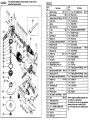
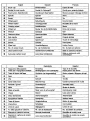
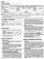
HITACHI
DISC GRINDER
WINKELSCHLEIFER
MEULEUSE
SMERIGLIATRICE ANGOLARE
HAAKSE SLIJPMACHINE
AMOLADORA ANGULAR
G 18SH l G 18U l G 18SE2 l G 18UA
G 18SG l G 18UB l G 23SF l G 23U
G 23SC2.G 23UA l G 23SE l G 23UB
Read through carefully and understand these instructions before use.
Diese Anleitung vor Benutzung des Werkzeugs sorgfaitig durchlesen und verstehen.
Lire soigneusement et bien assimiler ces instructions avant usage.
Prima dell’uso leggere attentamente e comprendere queste istruzioni.
Deze gebruiksaanwijzing s.v.p. voor gebruik zorgvuldig doorlezen.
Leer cuidadosamente y comprender estas instruccionesantes del uso.
Handling instructions
Bedienungsanleitung
Mode d’emploi
lstruzioni per l’uso
Gebruiksaanwiizing
lnstrucciones de maneio
G23SC2
*
The exploded assembly drawing should be used only for
authorised service facility.
G23SC2
I
Item
No.
I
Part Name
1
1I Machine
2
1Spring
3
4
1
5
I
6
7
r
9TSeal
I
10
1 14
I
I
I
Ass’y
M8
Ring (A)
I Washer (A)
1Ball Bearing (6301
I Rubber Ring (B)
I Felt Packing (A)
1Bearing Cover
15
Feather Key
16
Armature
17
Fan Guide
18
1 SidyHandle
I
I
I
1 41
43
Ball Bearing (6200WCM
1
I
I
I
1 51
1Brush
I
52
I Hex.
Socket Set Screw
1 53
I Dust
Packing
54
55
I
I
For Ml4
56-
e
I
Holder
Support
I
-~I
60
Tapping
I Handle
Screw (W/Flange)
16
I
61
Tapping
Screw (W/Flange)
D4 x 2 5
Screw (W/Flange)
D5~25
Tapping
Handle (A)
I Felt
D4x
(B)
63
[ Spindle
I
(D)
62
25
I
1
Nois Suppressor
fTube
Feather Key
4x4~8
M5x8
(B)
Ball Bearing (6302DDUCMPS2S)
26
I
I
DDUCMPS2S)
24
I
PS2S)
Ring (D)
23
I
I
Plate
Dust Seal (A)
E[mber
3X3XlO
I Bearing Cover (B)
1Name
42
59
22
Part Name
D5 X 35
I
I
I
Push Button
B
1 13
1
Item
No.
M5
Screw (W/Flange)
1Spring
1Gear Cover
1U-Nut
1Pinion
j
1 12
M5xl4
Washer
Tapping
1
1 11
Screw
I
I
I
Packing (B)
Hex. Socket Hd. Bolt (W/Flange)
EO
M8x22
1 Bolt
31
Wheel
32
Wheel Washer
33
D. C. Wheels
r%
1 Wheel
1 Patis
Guard Ass’y
Nut
35
Lock
Pin
36
Gear Ass’y
(A)
230MM
A24R
I
are subject to possible modification without notice due to improvement.
The drawing and the list are parts structural
drawing and parts list of model G23SC2.
For other models refer to the drawing and the
list.
English
Deutsch
6)
Brush cap
Burstendeckel
Francais
Capot de balai
@
Socket for side handle
Sockel fur Seitengriff
Douille pour poignee laterale
@
Push button (Spindle lock)
Druckknopf (Sperrplatte)
Bouton-poussoir (blocage d’arbre)
@
Spindle
Spindel
Arbre
@
Screw
Schraube
Vis
@
Wheel guard
Schutzhaube
Couvre-meule
@
Wheel washer
Unterlegscheibe
Rondelle de la meule
@
Grinding wheel
Schleifscheibe
Meule
@
Wheel nut
Mutter fur die Schleilfscheibe
Ecrou de la meule
1 Clef
1 Schlussel
1 @$ 1 Wrench
63
Diamond wheel
Diamantscheibe
Disque diamant
63
Side handle
Handgriff
Poignee laterale
@
Lock botton
Sperrknopf
Touch de verrouillage
63
Switch
Schalter
lnterrupteur
@
Wear limit
Verschleil3grenze
1 @I
CD
Usual carbon brush
Auto-stop carbon brush
@I
-T&o
1 CD
[
1 No. of carbon brush
~
1 Cappuccio
-~
della spazzola
I@
1 Presa
1 @
1 Tasto di blocco dell’asse
per l’impugnatura laterale
Nr. der Kohleburste
Limite d’usure
1 No. du balai en carbone
Gewohnliche Kohlebtirste
Balai en carbone ordinaire
Auto-Stop
Balai en carbone 31arr&
automatique
[ ~~~
~
Kohleburste
Nederlands
Bevestigingspuntvoorzijhandgreep
1 Drukknop
1
Espatiol
Tapa de la escobilla
Borstelkap
(as-vergrendeling)
Rosca para el asa lateral
1 Baton
pulsador (Bloqueo del eje)
1 @ 1 Asse
I k3
I Eje
1 @I
1 Vite
1 @
I Carter della mola
1 @
1 Rondella “graver”
1 @I
I Mola
1 Schroef
I Beschermkap
1 Onderlesqchijf
I Schuurschijf
1 Moer voor de schuurschijf
1 Tornillo
I Cubierta protectora
1 Arandela molar
1 Muela de alisado
1 Contratuerca molar
mado
ad anello
@
Chiave
Sleutel
Llave para tuercas
@
Disco diamantata
Diamantzaag blad
Adiamantado
1 @
I lnpugnatura laterale
1 @
1 Tasto di blocco
1 @
1 lnterruttore
t
I Handgreep
1 Vergrendelknop
1 Schakelaar
de muela
I Asidero lateral
1 Baton de seguridad
1 Conmutador
Limite de uso
69
Limite di usura
Slijtagegrens
@
N. della spazzola di carbone
Nr. van de koolborstel
No. de carbon de contact0
@D
Spazzola di carbone comune
Normale koolborstel
Escobilla de carbon usual
@
Spazzola di carbone ad arrest0
automatic0
Auto-stop koolborstel
Escobilla de carbc5n de parada
automtitica
GENERAL
OPERATIONAL
PRECAUTIONS
areas and
Keep work
area clean. Cluttered
benches invite injuries.
Consi&work
area
environment.
Don’t
expose
2.
power tools to rain. Don’t use power tools in
damp or wet locations.
Keep work area well lit.
Don’t use tool in presence of flammable liquids or
gases.
Power tools produce sparks during operation.
They also spark when switching
ON/OFF.
Never
use power tools in dangerous
sites
containing
lacquer, paint, benzine , thinner,
gasoline, gases, adhesive agents, and other
materials which are combustible or explosive.
3. Guard against electric shock. Prevent body contact
with
grounded
surfaces. For example;
pipes, radiators,
ranges,
refrigerator
enclosures.
4. Keep children away. Do not let visitors contact
tool or extension cord, All visitors should be kept
away from work area.
5. Store idle tools. When not in use, tools should
be stored in dry and high or locked-up place-out
of reach of children.
6. Don’t force tool. It will do the job better and
safer at the rate for which it was intended.
7. Use right tool. Don’t force small tool or attachment to do the job of a heavy-duty
tool. Don’t
use tool for purpose not intended-for
example
--don’t use circular saw for cutting tree limbs or
1.
logs.
8. Dress properly.
9.
10.
12.
13.
14.
15.
Do not wear loose clothing or
jewelry.
They can be caught in moving parts.
Rubber gloves and non-skid footwear are recommended when working outdoors.
Wear protective hair covering to contain long hair.
Also use face or dust mask if
Use eye protection.
cutting operation is dusty.
Don’t abuse cord. Never carry tool by cord or
yank it to disconnect from receptacle.
Keep cord
from heat, oil and sharp edges.
Secure work. Use clamps or a vise to hold work.
It’s safer than using your hand and it frees both
hands to operate tool.
Don’t overreach.
Keep proper footing and balance at all times.
Maintain tools with care. Keep tools sharp and
clean for better and safer performance,
Follow
instructions for lubricating and changing accessories. Inspect tool cords periodically
and if
damaged,
have repaired by authorised service
facility.
Inspect extension cords periodically and
replace if damaged.
Keep handles dry, clean,
and free from oil and grease.
Disconnect tools. When not in use, before servicing , and when changing accessories,
such as
blades, bits, cutters.
Remove
adjusting
keys and wrenches.
Form
habit of checking to see that keys and adjusting
wrenches are removed from tool before turning it
on.
Avoid
unintentional
starting.
Don’t
carry
plugged-in tool with finger on switch.
Be sure
switch is off when plugging in.
17. Outdoor use extension cords. When tool is used
outdoors,
use only extension cords intended for
use outdoors and so marked.
what you are doing. Use
18. Stay alert. Watch
common sense. Do not operate tool when you
are tired.
19. Check damaged parts. Before further use of the
tool, a guard or other- part that is damaged
should be carefully checked to determine that it
will operate properly and perform its intended
function.
Check for alignment of moving parts,
binding of moving
parts, breakage
of parts,
mounting,
and any other conditions that may
A guard or other part that is
affect its operation.
damaged should be properly repaired or replaced
by an authorised service center unless otherwise
indicated elsewhere in this instruction manual.
Have defective switches replaced by authorized
service center.
Do not use tool if switch does not
turn it on and off.
20. Use the power tools only for applications specified in the Handling Instructions
21. To avoid personal injury, use only the accessories or attachment
recommended
in these
handling instructions or in the HITACHI catalog.
Let only the authorized
service facility do the
repairing.
The manufacturer
will not be responsible for any
damages or injuries caused by repair by unauthorized persons or by mishandling of the tool.
23 To ensure the designed operational integrity of
power tools, do not remove installed covers or
screws.
24 Do not touch movable parts or accessories unless
the power source has been disconnected.
25 Use your tool at lower input than specified on the
the finish may be spoiled
nameplate;
otherwise,
and working efficiency reduced by motor overload.
26. Do not wipe plastic parts with solvent. Solvents
thinner,
benzine,
carbon
such
as gasoline,
tetrachloride,
alcohol, ammonia and oil containing chloric annex may damage and crack plastic
parts. Do not wipe them with such solvent.
Wipe plastic parts wit h a soft cloth lightly
dampened with soapy water.
27. Use only original HITACHI replacement parts.
28. Disassemble this tool only for replacement of
carbon brushes.
29. Use the exploded assembly drawing on this handling instructions only for authorized servicing.
PRECAUTIONS
ON USING
DISC GRINDER
1. Never operate
these power tools without Wheel
Guards.
2. Use only grinding wheels with a “Safe Speed” of
at least as high as the “No-Load RPM” indicated
on the power tool nameplate.
3. Always hold the body handle and side handle of
the power tool firmly.
Otherwirse the counterforce produced may result in inaccurate and even
dangerous operation.
4. Never depress the push button while the spindle is
turning.
’
English
1
SPECIFICATIONS
Model
Gl8St-I~ Gl8U
[Gl8SE2~Gl8lJA~Gl8SGlGl8UBlG23SF[
Voltage (by areas) *l
(11 OV,
Input*’
1
2000W
I
No-load speed
Outer dia.
Wheel
22OOW
85OO/min
115v, 120v, 127V,
1 ~4tXN,A/ 1
I
G23U lG23SC2lG23UAlG23SElG23UB
22OV, 23OV, 24OV)-
1
2000W
1
2200W
2400W
I
66OO/min
230mm
18Omm
Inner diam.
22mm
Peripheralspeed
Weigth*2
48OOm/min
4.3kg
Starting current limiter*3
No
5.Okg
Yes
No
Yes
5.Okg
4.3kg
No
Yes
No
Yes
No
Yes
No
Yes
* 1 Be sure to check the nameplate on product as it is subject to change by areas.
*2 WeiQht: Onlv main bodv
*3
The starting current limiter produces the starting current to such an extent that a fuse (16A, slow-blow) is not tripped.
STANDARD
ACCESSORIES
(I ) Wrench . . . . . . . . . . . . . . . . . . . . . . . . . . . . . . . . . . . . . . . . . . . . . . . . . . . . . . . . . 1
(2) Side Handle . . . . . . . . . . . . . . . . . . . . . . . . . . . . . . . . . . . . . . . . . . . . . . . . . . . 1
Grinding
sories.
Standard
notice.
wheels
are not provided
accessories
are subject
as standard
to change
acceswithout
APPLICATIONS
0
Removal of casting fin and finishing of various
types of steel, bronze and aluminum materials and
castings.
0 Grinding of welded sections or sections cut by
means of a cutting torch.
0 Grinding of synthetic resins, slate, brick, marble,
etc.
o Cutting of synthetic concrete, stone, brick, marble, and similar materials.
PRIOR
TO OPERATION
1. Power source
Ensure that the power source to be utilized conforms to the power requirements specified on the
product nameplate.
2.
Ensure that the setting screw is thoroughly tightened after adjusting the wheel guard.
5. Ensure that the grinding wheel to be utilized is the
correct type and free of cracks or surface defects.
Also ensure that the grinding wheel is properly
mounted and the wheel nut is securely tightened.
Refer to the section on “Grinding Wheel Assembly”.
6. Conducting a trial run
Before
commencing
grinding
operation,
the
machine should be given a trial run in a safe area
to ensure that it is properly assembled and that the
grinding wheel is free from obvious defects.
Recommended
trial run durations are as follows:
After replacing grinding wheel
..*..............................
3 minutes or more
Prior to starting routine work
. . . . . . . . . . . . . . . . . ..*............. 1 minutes or more
7. Confirm the spindle lock mechanism.
Confirm that the spindle lock is disengaged
by
pushing push button two or three times before
switching the power tool on (See Fig. 1)
8. Fixing the side handle.
Screw the side handle into the gear cover.
PRACTICAL
To prolong the life of the machine and ensure a
first class finish, it is important that the machine
should not be overloaded by applying too much
In most applications,
the weight of the
pressure.
machine alone is sufficient for effective grinding.
Too much pressure will result in reduced rotational
speed,
inferior surface finish, and overloading
which could reduce the life of the machine.
Power switch
Extension cord
When the work area is removed from the power
source, use an extension cord of sufficient thickness and rated capacity.
The extension cord
should be kept as short as practicable.
4.
Fitting and adjusting the wheel guard
The wheel guard is a protective device to prevent
injury should the grinding wheel shatter during
operation.
Ensure that the guard is properly fitted
and fastened before commencing grinding operation.
By slightly loosening the setting screw, the
wheel guard can be turned and set at any desired
angle for maximum
operational
effectiveness.
APPLICATION
1. Pressure
Ensure that the power switch is in the OFF position. If the plug is connected to a power receptacle while the power switch is in the ON position,
the power tool will start operating immediately,
which could cause a serious accident.
3.
GRINDER
2.
Grinding angle
l
Do not apply the entire surface of the grinding
wheel to the material to be ground.
As shown in
Fig. 2, the machine should be held at an angle of
15“-30’ so that the external edge of the grinding
wheel contacts the material at an optimum angle.
3. To prevent a new grinding wheel from digging into
the workpiece,
initial grinding should be performed by drawing the grinder across the workpiece
toward the operator (Fig. 2 direction B). Once
the leading edge of the grinding wheel is properly
abraded,
grinding may be conducted
in either
direction.
English
of the motor
5 Maintenance.
4. Switch operation
Th ct nm
hwth d o w
evio t“ nsa hi o e
ntn oh
S
O
P w t
lN
u bi h
of :
s ut a e o
c
rk u
ii nt
E
ccxw
t roe u
aheet
o .
t
p
t
hs
r l
h
ew
e e
e
npi
s vt
to
s eo d
* F
c
o u o
tt s n
e nae s a tdw c
p
r w - h e t d e ni
eb , i o sd on
s
l
w
i
T
s e
l h
i wv
ew te o
s io e w v i c i t r r a et h l c . t rh
h
l
b p
o
t
yl u
cb h
o s
ku e
c h
et
k i
di n
t
f
oo
oa
nn
rg
c
wa
e
ai
n
r
d.
(* S
t c
u d
o h o b e NOTE
a
nj p
n
e e
g
c n
e
t
a
)
r
e
D a t H
u . co I
pe o T o r
r
n A
s
O
P w a Fr
r ti ns Fe
l e th dw :l
eas ce d i e
vns h te t sa
ed
r a ee h
hv c h
ps
s
t c
u w o hp b n i
a r j ot
after
finishing
5 Precautions . immediately
operation
A
s
f o
tw m
t f
hdi n a pe f i eot
o c ur t c
th t
h
i
i
n
d
u
t og
n
wh w r h t c he t ni aa i o e o n s l m e
d
e l
i
n
c
s
oA
f t a mp
sr o v a pa
o
e p o cl r
m
r .
i ce t
i
d it
o
i -e
m
B
8
e
1
.
0
n
9
S
0
t
7
.
d
t
p e
h w rr n
t i ia ee t o h s l
cd s f e l o au ,
u uc
n te
it s a qp d i
sfo T
p up n
d
a
s
us
n i w t su m d n a h tc a
tT r er k c
ohf i ea e h
U
K
N
I
I
N
T
G
W
t
m
h i hn
i a u e t s peo n c s nh
ot
he
o
e
w
i ,u
e
n r
r
e c
s
b d
h
e i
o
s
u
c
l
o
d
n
n
IMPORTANT
Correct connection of the plug
T
w
o t h mi
l f hae car
e
ier a oie
a
GRINDING
WHEEL
ASSEMBLY
d
w
t
af
i
ch
n
o
t
oe
cl
h
B
l
N
u
e
e
lmAssembling (FQ. 1)
(
T
t
m1
u uh
a)
r s pt e
t c s no h
s
h hB p
ia - e i r i
dt L
no n
e i
ew o
ig ft h
e mdli
l n ho et a .or
d
i f
u l
s a
pe
c
w
iA t
ac
n so ht
rw
m
ow e no ot
cy
t i r drmlh
o
t
(
M
t
2w
o w h
o
)h
ut a s e
ne
h
n s pt
te
en
t h ci o
oal
i t he
hi y
eb
e e pd
n
pe o
ne
r l al i
(
F t
p 3
i h
or t )
gt e
fo wh
ro
i r t dut e
n
d
w
io
t
hw
a nw
h
eh
mt a
ef
ee
oo s o
le
n h l
l
d e l
Tt
w
h
bli
m
e b rcl
te tu
eo
(
S
t
4w
c n
h
o
)ht
rs u
e
n
eh ep t
ee wic
o
no
dl u
lo
r N
i o ehc r e dmb bt r l eo k
(
d
wF
ia
ho ua s t
w er
smst h
h em e oe ew e t l a l nm
T i wa v c e eh a bii e o m e m
b rrnc x l u
teo oetso
o
n
w
t
cu
i s h a ot
tt i de g n
hh d
t
m
e w
t .a l
r Li o c
h re
mrt r o
e k
w
)
h
e
e
l
N
c
m
e
b
c
o
u
i
t
e
t
o
r
e
s
t
t
o
h
n
e
(
I
t
p5
nb
h t u
p)
su r e o s
r o tet o
eh f hrt t
v
eto a
e
n t
n
.
s
a
t p
t nw i i n
h
w d ha g n u
ein
ec h d t
ta
ec t l
hl
le e e
sn ,
NOTE
s
w
ao s r
i F sr 1h e
n Q y. o n
.
w c
n h
,
T
r
h
i
e
p
a
i
s
q
r
t
B
s
c
uo
2. Disassembly
S v o vc
2 T e 1
7 A
9 rd
6 N
8 su
F
t
a
o p
h
b il r r
e
o nl eo
w ee
T
t
hl
c
ha ee c
o c en m
tr o n d o
b a
te op
m
o
tep
aT
U hxl
r
K
i
n
g
MAINTENANCE
AND
INSPECTION
Inspecting the grinding wheel
h e abo etd emp e l tcyi hi i m
io
oks i ins
E
t
t ng
h wh s r i f a o hec ui s r t Tf e rn rn ee
a e
1 Cs E4
0O
a
s
d n
u
e d
r
f
f
a w c I c 5 c( i c1 E t I 9 7C
e t oD
6
P
2
3N
3
a
1
(5F
1
r
,
8f S c tInspecting the mounting screws:
R
i
e a m r
gs l
o as e uc l
u ncp n blr
n dre Ts are s
t ecp hu rew o l i t tra er t las u e
; r i 5t nBl ce Ack n l n h
t
t
a
ph
h t r
ra
eS i e a ot o yh g w n p f co h eo y e 8 ad
u t (xr
rhs deet
e
t
s
b h
l
c r
e oet r ei
oh e m
t p
s e wf i m t r o e m sog i ehro p ,
F
t d s ac
or o oi i so
e h
n l eu
s a
u rl
u z
r id
l a
eo
t r
u
Inspecting the carbon brushes (Fig. 3)
T
M
e h
oc
m eb
t a w p ra o r h l ur
r b i o se
o c y h
n h s e
c
p o
a n
t s
i u
s m
.
a
b
W
t
b h
h
w
et eo n eo t oc “ nr e yr h o w
a n e me
r
ea
r
l
i c
ir
ti om
met
n uoW isr a
l t h t uo n
do e ” lu
r n , tb
l
a
c
u
b
ia e t
r
t sr qm
o
u
h b uo
s
e o i st
h
n po
h
p ro
w
s
a
i
t
u
l
o
t
l
p
o
m
a
t
A t
t
rt h
ib
ce a
bmo
apw t
r et
rl i
uh
,
ba t
s
och
h
ne
n
o
w e
hn
t h sw a ec h i b
a
v sa e c m
r
e r
h ue
b
s
o
h
N
s
ui t
f h
mIn ah
i o a nb de g w l e d u n w r i
r
a s t
e
y
i
k
c
be
ac
ar e e r l
t n
u pt n b e h d
s h s o a a h e u nn t
ey r
s
e
s
f
w l
t r b
i hi
he r
t od
ee u
h le
l s
i d
y h n e
r
4
Replacing
D
s
r
.a carbon
t i b
Tc c
e
brush:
c hw
s r a ma ea
i u
b hr c a t
rb ee a r h
m
o
i p
ue
ts s
n
aw nb e
s
v
hs h
u
sd o n
h
e
e
i r n
d
s
m
l i
.