1
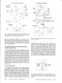
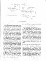
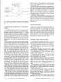
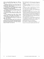
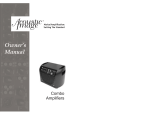
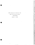
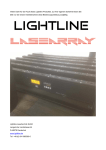
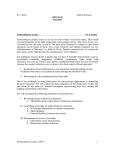
A narrow-bandtunablediode laser system with gratingfeedback,
and a saturatedabsorptionspectrometerfor Cs and Rb
K. B. MacAdam,")
A. Steinbach,and C. Wieman
Joint Institute for Laboratory Astrophysics and the Department of Physics, Uniuersity of Colora1o,
Boulder, Colorado 80309-0440
(Received 6 February 1992; accepted26 June l99Z)
Detailed instructions for the construction and operation of a diode laser system with optical
feedback are presented. This system uses feedback from a diffraction grating to provide a
narrow-band continuously tuneable source of light at red or near-IR wavelengths.These
instructions include machine drawings for the parts to be constructed, electronic circuit
diagrams,and prices and vendorsof the items to be purchased.It is also explainedhow to align
the system and how to use it to observe saturated absorption spectra of atomic cesium or
rubidium.
I. INTRODUC]TION
Tuneable diode lasersare widely used in atomic physics.
This is primarily because they are reliable sources of
narrow-band ( < I MHz) light and are vastly less expensive than dye or Ti-sapphire lasers.However, the frequency
tuning characteristicsof the light from an ,.off the shelf"
laser diode is far from ideal, and this greatly limits its
utility. In particular, the laser output is typically some tens
of MHz wide and can be continuously tuned only over
certain limited regions.Thesecharacteristicscan be greatly
improved by the use of optical feedbackto control the laser
frequency. Reference I gives a lengthy technical review of
the characteristicsof laser diodes, the use of optical feedback techniquesto control them, and various applications
in atomic physics. An earlier review by Camparo2 also
gives much useful information, primarily relating to freerunning diode lasers. The use of a wavelength-dispersive
external cavity for diode laser tunning and mode selection
was described by Ludeke and Harris,r and the spectral
characteristics of external-cavity stabilized diode lasers
were investigatedin detail by Fleming and Mooradian.a
During the past severalyears our laboratory has carried
out a large number of experiments in optical cooling and
trapping, and general laser spectroscopyofcesium and rubidium using diode lasers. In the course of this work, we
have developed a simple inexpensive design for a diode
laser system that uses optical feedback from a diffraction
grating. This system produces over l0 mW of light with a
bandwidth of well under I MHz and can be easily tuned
over atomic resonancelines. We now have over a dozen
such laser systems operating, including two in an undergraduate teaching lab, and the design has reached a reasonablelevel of refinement. There are many other designs
for optical feedback systemsl and we make no claims for
this one being superior. However, it is a reasonablecompromise between several factors which are relevant to
1098
Am. J. Phys. 60 (12), December 1992
many laboratories:( 1) low cost (about $400 not including
labor), (2) easeof construction(severalof thesesystems
have been built by novice undergraduates),and (3) reliability. These lasers have achieved several notable successesin experimentson cooling and trapping cesium atoms, and the design has been successfullyduplicated in a
number of other laboratories. we prepared this article in
responseto a large number of requestsfor detailed instructions on how to build and operate such a system. This
article provides a detailed and fully comprehensiverecipe
for construction of the system and its use to observesaturated absorption spectra in a rubidium or cesium vapor
cell. we refer the reader to Ref. 1 and the references
therein for information about the physics of laser diodes
and the factors that motivated this design as well as design
alternatives.
In this paper, we have attempted to respond to three
frequent requests for information we receive. The first is
from the undergraduate wanting to do high-resolution laser spectroscopyfor a project, without expert local supervision. The second is from the faculty member who wants
to construct a teaching laboratory experiment and wants
instructions that can be given to a technician or undergraduate with favorable results. The third is from the research
scientist who wants to use diode lasers in an experiment
and would like to benefit from the accumulated practical
experiencein another laboratory.
We will first discussthe construction or purchase of the
basic components and then explain how to put them together, align the laser system, and tune the frequency. Finally, we discusshow to observesaturatedabsorption spectra and how to use these spectra to evaluate the laser
performance or to actively stabilize the laser frequency by
locking it to narrow saturated absorption features.
@ 1992 American Association of Phvsics Teachers
1098
Fig. l. Assembly top view of laser. The arrow showing the blaze direction
on the grating is for the low feedback-largeoutput case.
II. SYNOPSIS OF COMPONENTS
As shown in Fig. l, the laser system has three basic
components,a commercial diode laser, a collimating lens,
and a diffraction grating. These components are mounted
on a baseplate.The laser and lens are mounted so that the
lens can be carefully positioned relative to the laser to
insure proper collimation. The diffraction grating is
mounted in a Littrow configuration so that the light diffracted into the first order returns to the laser. As such, the
grating servesas one end "mirror" of a laser cavity, with
the back facet of the diode providing the second mirror.
This means the grating must be carefully aligned and very
stable.To achievethis we mount the grating on a standard
commercial mirror mount which is attached to the baseplate. As with any laser, changesin the length of the cavity
cause shifts in the laser frequency. Therefore, to obtain a
stable output frequency, undesired changes in the length
due to mechanical movement or thermal expansion must
be avoided. To reduce movements due to vibration of the
cavity we mount it on small soft rubber cushions.To avoid
thermal changes, the baseplateis temperature controlled
using heaters and/or thermoelectric coolers. In addition to
controlling the temperature of the baseplate,we independently control the temperature of the laser diode. Finally,
to avoid air currents interfering with the temperature control we enclosethe entire laser system in a small insulated
metal box. Of course,to finely tune the laser frequency one
must have some way to change the length of the cavity in
a carefully controlled manner. We do this using a piezoelectric transducer speakerdisk which moves the grating in
responseto an applied voltage.
The laser system also requires a small amount of electronics. A stable low-noise current source is neededto run
the laser, and temperature control circuits are used to stabilize the diode and baseplatetemperatures.This electronics is readily available commercially. However, for those
1099
Am. J. Phys., Vol. 60, No. 12, December 1992
with more time than money, we provide circuit diagrams
for the relatively simple circuits that we normally use.
This system contains both purchased and "homemade"
components. Before discussing the construction aspects,
we will provide some information concerningthe purchasing of the commercialcomponents.We purchasethe diode
laser itself, the collimating lens, the fine adjustment screw
which controls the lens focus, the diffraction grating, the
mirror mount which holds the grating, and the piezoelectric disks. The purchaseof most of theseitems is straightforward. Fine adjustment screws and mirror mounts are
available as standard items from most companies that sell
optics hardware. Similarly, laser diode collimating lenses
and diffraction gratings are available from numerous companies. For the convenienceof the reader we list in the
Appendix the exact products we use along with the prices
and vendors.However, for these items our choice of vendors was primarily determinedby expediency,and we have
no reasonto think that other vendors would not provide
equal or superior products.
In contrast, in order to obtain satisfactorylaser diodes
and piezo disks we have tried and rejected a large number
of different vendors. Piezo disks are widely sold as electronic speakersand are very inexpensive,but most models
are not adequatefor this application.The Appendix gives
the only suitable product we have found. The purchasing
of diode lasers can be filled with frustrations and pitfalls,
and we refer the reader to Ref. 1 for a full discussionof the
subject.Here, we shall just give a brief summary of what
must be specified,and our recommendationsfor suppliers.
The basicrequirementfor a diode laserwhich is to be used
in this systemis that it have a high reflectivity coating on
the back facet and a reduced reflectivity on the front, or
output facet. Very inexpensivediodes which produce a few
milliwatts of power have two uncoatedfacets,and will not
work very well. We have used 20-mW lasers, but their
performance is marginal. However, we have found that any
laser we have tried that is specifiedto provide 30 mW or
more singlemode will have the necessarycoatingsand will
work well.) It will provide narrowband laser light that is
tuneable over 20-30 nm. If one wants this range to cover
the 852-nm cesium or 780-nm rubidium resonancelines,
the diode laser wavelength must be specified when purchasing.This greatly complicatesthe purchasing.We have
tried numerous suppliers, but have now settled on STC as
our supplier of lasersfor 852 nm and Sharp as the supplier
for 780 nm. The Sharp lasersare far lessexpensiveand can
usually be obtained rather quickly since 780 nm is near the
center of the distribution of their normal mass-produced
product. This is not the case for 852 nm, and thus the
lasers must be produced as a custom run. STC has made
several such custom runs and hence usually has 852-nm
lasers available although they cost 3 to 4 times more than
the Sharp lasers. The long wavelength edge of the distribution of Sharp lasers is at about 839 nm, and we have
used such lasers to reach the cesium line by heating them.
However, it can be difficult to obtain 839-nm lasersand to
obtain reliable performance when tuning the laser this far
from its free-running wavelength. The heating of the laser
also degradesits lifetime.
The remaining components of the laser system are
homemade. The key components are the laser mounting
block which holds the actual diode laser, the holder for the
collimating lens, and the baseplateonto which all the comK. MacAdam, A. Steinbach, and C. Wieman
1099
L A S E R D I O D E M O U N T I N GB L O C K
D R I L L B L I N Dr
HOLETO
l i E bE ' uE
1.125
F
THERMIS.TERi
-
-
o8o7 +
*
0.563+
!.
|
,'o.sta
C O L L I M A T O RL E N S M O U N T
0 . 2 1I
DEPTH
0 . 16 4
DEPTH
SIDE
VIEW
-,: rT
A"
f
FRONT
VIEW
, IHut
0.875
0.500
0.02
0.356D1A
0.2s0
FRONT
VIEW
stDE
VIEW
0.356D
tA
TO FIT
LENS
t
1 000
O P E NT O 0 . 1 5 0x 0 . 2 7 5
W I T H3 / 3 2 ' E N DM I L L
0.375
0 . 1 2 5-
0.040
t
;-7-$
TOP
VIEW
l
BOTTOM
VIEW
o o+o
] | . o 3 7 5r R E L I E V ET O o . o 2 o "
r . 1 8 8 1 i l D E P T HF O R S T A B I L I T Y
v
r
;0.040
I
0 040
ASSEMBLY
(cuT AWAY)
4.40 SCREEN
+ WASHER
ALIGNMENT
JIG
3 0 .B E V E L
F O RB E A M
CLEARANCE
0.688 ,
TOP
VIEW
nrr\ ntr
-l
Fig. 2. Laser mounting block, machine drawing. Dimensions are in
inches. The hole sizes, spacings, and depths are correct for a Sharp
LT025MDO laser and may be modified for other types.
ponents are fastened. In addition, we also make the box
that enclosesthe system and a small jig that is useful for
setting the position of the collimating lens. All thesecomponentshave beendesignedso that they can be constructed
by a novice machinist.
III. INSTRUCTIONS FOR CONSTRUCTION OF
LASER COMPONENTS
Constructionof the diode laser systembeginsin the machine shop and primarily requires a milling machine and
drill press.Detailed machine drawings for the laser mounting block, baseplate,collimating-lensholder, and an alignment jig are given in Figs. 2 and 3. In addition, an enclosure should be fabricated, but its design is not critical. We
provide dimensions for mounting the standard Sharp laser
package. Small changes may be needed for lasers from
other vendors. In view of the setup time required in machining, and the fact that many interesting experiments
with diode lasers require more than one of them, it will
probably be found economicalto make two (or more) systems at once.
I
Fig. 3. Collimating lens mount and alignmentjig machine drawing. Dimensions are in inches.
"bridge" design has been found to make a significant improvement on laser cavity stability. The 0.356-in. diam
hole to receive the diode package may be made either by
boring on a lathe fitted with a four-jaw chuck or, more
easily,by a suitable end mill. Reground 3/8-in. end mills
can often be found near this diameter. Some deburring or
filing may be necessaryto allow the diode to fit snugly into
its recessbut allow it to be rotated to its proper orientation
in the initial step of alignment. A small hole whose diameter is selectedto fit the thermistor should be drilled into
the back side of the mounting block near the diode recess.
LD
A. Laser mounting block
The laser diode is held firmly in a small aluminum block
whose details are shown in Fig. 2. The critical dimensions
are the 0.500-in. height of the laser center above the baseplate and the depths of holes that ensure that the 9-mm
flange of the diode package is gripped by the mounting
screws.For stability when the block is screweddown to the
baseplate,the bottom surface of the block should be machined as shown with a 0.020-in.relief cut down the middle so that contact is along the edges of the block. This
ll00
Am. J. Phys., Vol. 60, No. 12, December 1992
@.'J
I
t,
F i g . 4 . J i g u s a g ei n c o l l i m a t i o n . L D : l a s e r m o u n t i n g b l o c k ( F i g . 2 ) ,
C:collimating lens mount (Fig. 3),
"/:alignment jig (Fig. 3). Sp
:spring or rubber pad to provide a restoring force against adjusting
screw 52.
K. MacAdam, A. Steinbach,and C. Wieman
1100
SAW SLOT TO
F O R MH I N G E .
this time will allow comparison of laser performance with
different cavity lengths without complete disassembly of
the collimated laser.
O F D R I L LA N D R E A M E R
D. Grating and grating mount
D I O D EL A S E R B A S E P L A T E
4-40 CLR
r\
l*f
0 . 18 8
l l ,/
40TAP 1/
R E A MH O L E
TO ACCEPT
PRECISION
SCREW
B U S HI N G .
l-t srsz>l
F__z srro_l
0.6s6
1. 0 9 4
v
D R I L LC L E A R A N C E
H O L E ( SF) O RS C R E W
T O A T T A C HG R A T I N G
MOUNT.
M A T E R I A L S : A L U M . 1 t 2 "T H K .
IN INCHES
DIMENSIONS
Fig. 5. Laser baseplate,machine drawing.
B. Collimator lens mount
Figure 3 shows the aluminum block that holds the
flanged collimator lens. The placement of the lens axis at
0.500 in. above the base and the diameter of the hole are
again the critical dimensions.The 30" bevel shown on the
front side of the block allows clear passageof the output
beam off the diffraction grating when very short cavities
are used. The figure also shows dimensions of a suggested
alignment jig that is used to allow transversedisplacement
of the lens holder without rotation or longitudinal movement. A 2-56 screw with rounded tip and a small piece of
bent spring steelor resilient cushion should be prepared for
use with the jig (as shown in Fig. 4).
C. Baseplate
The baseplateis shown in Fig. 5. We have found that
aluminum is adequate for most purposes and is easy to
machine. If greater thermal stability is required, however,
the baseplatecan be made of invar. The two pairs of 4-40
holes should be carefully positioned to match corresponding holes in the laser and collimator-lens blocks. The single
4-40 tapped hole is used to mount the alignment jig. The
most obvious feature of the baseplateis its flex hinge design, which allows smooth variation of the spacingbetween
diode and collimation lens by action of a commercial precision screw mounted to push against the hinge. The slot
that forms the hinge can be cut by a bandsawafter all holes
are laid out. The hole intended to receive the precision
adjusting screw should be reamed to allow a fit without
excessclearance. After all machining of the baseplateis
complete the screw can be mounted in this hole with adhesiveor by a set screw. The web that provides the flexible
hinge should be left l/16 in. or more in width: One can
always remove material later if it proves too stiff. One or
more holes should be drilled in the baseplateto mount the
diffraction grating holder, but the exact position(s) depends on the dimensions of the holder and grating and on
the desired cavity length. Several suitable holes drilled at
Am. J. Phys., Vol. 60, No. 12, December 1992
The baseplate design is intended for use with a 1200
line-per-mm grating. Suitable gratings are readily obtained
with 500- and 750-nm blazes and dimensions I x 1x 3/8
in. thick. When mounted, the grating has its rulings vertical and diffracts its first-order interference maximum back
into the laser. The output beam is the zero-order beam or
specular-reflection maximum, which passes horizontally
beside the collimator block and out of the enclosure. The
direction of the blaze is toward the output beam. A laser
diode whose free-running wavelength is within about 3 nm
of the desired wavelength requires less feedback for stabilized operation than a laser that must be pulled more severely. For this case,lower diffraction efficiencyand thus a
shorter blaze wavelength (500 nm) is suitable, and this
allows more power to be brought out in the zero-order
beam. If a laser must be pulled more severely,a longer
blaze wavelength (750 nm) is used to provide stronger
feedback at the price of lower output power.o
When a grating of suitable blaze has been selectedit may
be cut down to a small sizesinceonly about 0.3 in. parallel
to the rulings and 0.5 in. perpendicularis required. Thus
several gratings can be had for the price of one, and the
others may be used to duplicate the diode laser system or
for testing grating properties outside the laser. The cutting
may be safelydone as follows. Apply a generouscoating of
clear acetatefingernail polish to the ruled face of the grating. Spreadthe fluid using a soft camel's hair brush, and
avoid physical contact with the grating. After the coating
is thoroughly dry, wax the back of the grating to a block of
bakelite or pherrolic to support the grating while it is
sawed.Mark the coated surfaceof the grating into piecesof
the desired size, A I X 1 in. grating will yield six suitable
pieces.Saw the grating in an abrasive-wheelglasssaw by
holding the support block on its edge as the saw cuts directly into the face of the grating. Make sure the saw cuts
penetrate completely through the grating into the support
block without severing the block. Then melt off the cut
segments.The nail polish can then be removed by submerging the grating segmentsin a small beaker of methanol and placing the beaker in an ultrasonic cieaner. Remove the gratings with tweezers, being very careful to
avoid any contact with the now-exposed ruling surface,
refill the beaker with fresh methanol, and repeat once or
twice until the gratings, when drained and dried, appear
completely clean. Harsher solvents may attack the plastic
substrateof replica gratings, but methanol has been found
to be safe and effective.
After cleaning, the grating is attached to the movable
face of the grating mount in a location where the collimated laser beam will strike near the middle of the grating.
Care should be taken to make the rulings vertical. A stiff
but readily removable adhesive such as Duco cement is
recommendedfor attaching the grating to the mount. The
grating segmentcan be easily damagedwhen it is necessary
to remove it or shift its position unless it can be detached
with little physical force. If necessary,the efficiency of
most inexpensivegratings at the 852-nm wavelengthfor Cs
can be improved by lOVo-ZU%by evaporating a gold coating onto the grating before it is installed.'
I l0l
PZT should be inserted between the mounting plate and
the ball end of the adjusting screw as shown in Fig. 6.
Small pieces of mylar should be inserted to electrically
isolate the PZT from the mount. The PZT will provide
about + 1 /rm of displacementwhen + 15 V are applied.
F. Enclosure for the laser
TO
TRIANGLE
WAVE
GENERATOR
S O F TS O L D E
(4 places)
"/
Fig. 6. Piezoelectricdisks (not to scale).
Before the grating is attached to the mount, the mount
should be modified, if necessary,so that it has the same
"bridge" profile on its base as described earlier. In addition, the grating mount should be modified so that its adjustment screws can be turned by a ball-end wrench
through holes in the temperature-control enclosure of the
assembledlaser. A good way to do this is to remove the
heads from l/4 in.-20 socket screws in a lathe and to attach them to the centers of the knobs of the adjustment
screwswith epoxy cement.
An aluminum enclosureshould be fabricatedto hold the
laser.It should have a sufficientthermal massand conductivity to aid in temperaturestabilization.Such a box can be
made out of rectangular side plates screwed together,
placed on a rectangularbaseplate,and cappedby a lid, or
a singlepieceof hollow rectangulartubing may be selected
to form the walls. Wall thicknessshould be l/4 to l/2 rn.
Inside dimensionsabout 3.5 in. wide, 5.5 in. long and 4 in.
high are adequate.The floor of the enclosureshould stand
on some firm support, to bring the laser output beam to a
desired height above the table. The lid of the enclosure
should be easily removableto allow frequent accessto the
laserwith minimal disruption of the thermal or mechanical
stability. After the laser is assembledand satisfactorily
aligned,drill holesin the box to allow accessto the grating
adjustmentscrewsand drill an openingto allow exit of thi
laser beam. Thesestepsshould be delayeduntil one knows
for certain where the holes should be placed. The output
aperture is ultimately covered by a microscopeslide, and
the accessholes should be plugged to limit air currents.
Tapped holes on opposite edgesof the bottom plate of
the enclosureallow the laser structure to be anchoredonto
the vibration isolation pads discussedbelow, for instance
by stretching a rubber band over the laser baseplateand
looping it over screw headsin the edgesof bottom plate.
The bottom edgeof one of the sidewalls of the enclosure
should be provided with a notch or channelat both ends of
the laser for egressof all wires. Soft rubber placed in the
notchescan serveto pressthe wires firmly againstthe bottom plate, and in this way the movement of wires outside
the box will not transmit stressor vibration to the laser
structure. Finally, one should make sure the enclosureis
electrically grounded.
E. Piezoelectric disks
Piezoelectric (PZT) disks are inserted betweenthe grating mount adjustment screw and the movable face of the
mount in order to rotate the grating about a vertical axis
and alter the cavity length with electricalcontrol (Fig. 6).
Each PZT elementconsistsof a thin brass backing about I
in. in diameter to which a thin smaller-diameter silverplated piezoelectric slice is attached in the center with adhesivearound its edge.When voltage is applied, the piezoelectric stresscausesthe backing to "dish" on the opposite
side. Two such elements can be attached back to back,
doubling the displacement of a single one, by lightly soldering the adjacent brass backings at four places around
their circumference. If necessaryfor clearancein the grating mount, some of the excessbrass can be clipped away
without damaging the piezoelectric center. The double
PZT is wired by lightly soldering one connection to the
brass and the other to the two silver-plated piezo elements
in parallel. For this and all other wiring of the laser, it is
best to select a limp insulated wire that will not transmit
vibration to the laser structure. Rubber coveredNo. 24 test
prod wire has been found suitable. After thepZT is assembled and wired, and the grating is glued to the mount, the
ll02
Am. J. Phys.,Yol.60,No. 12,December
1992
IV. TEMPERATURE CONTROL
Precisecontrol of the temperature of both the baseplate
and the diode laser itself is essential for the long term
reliable operation of the laser at a particular wavelength.
We control thesetemperaturesusing identical independent
servosystems.The sensingelement for the servo is a small
thermistor, which is part of a bridge circuit. The amplified
and filtered error signal drives a heater or thermoelectric
cooler. In this area of thermal control we have made the
largest compromises of potential performance in order to
simplify the mechanical and electrical designs.part of the
reason we are willing to make this compromise is that we
usually sensethe output frequency of the laser and lock it
directly to atomic transitions to insure long term stability
at the sub-MHz level. This is discussedin Sec.X.
The temperature of the diode laser mounting block is
controlled only by heating, which means that it must be
kept l-2 "C hotter than the baseplatefor proper temperature control. The heating is done by a small (0.3X 1.5 in.)
adhesivefilm heater which is attached to the top or side of
the laser mounting block. The sensingthermistor rests in a
small hole packed with heat sink compound in the mountK. MacAdam, A. Steinbach. and C. Wieman
ll1z
fhe res rstors on Sl are each
metal f il,m resrstors.
K.t
l.5K
4.99k
R56*c
T H E R NI S T O R
soKg
ROOr,l
TENP
B
13,
c1
luF
Cl and C? are
polvstyrenc
capacrtors.
R6
15rl
. ttt:
l"
=
I
=
q
t,Dl
-0r
n:+tses+-"
tltX R e sr s t o r s
Ll
netal
I
lPtt su
oi.
|z
I
Sz
are
frIm.
Fig. 7. Temperature control circuit.
ing block. The temperaturecontrol circuit which drives the
heater is shown in Fig. 7. Although this circuit is rather
crude compared to what is usually used for precision temperature control, we have found it adequatefor most purposes.It is simply a bridge, an amplifier and an RC filter
which rolls off the gain as l/frequency, for frequencies
between 0.005 and 0.50 Hz. The componentshave been
chosenso that above 0.5 Hz the electrical gain is constant.
This frequency responsewas selectedso that the combination of this electrical responseand the thermal responseof
the laser mounting block results in a net servo gain which
goesnearly as l/f . The gain is set by the 5-kO potentiometer to be just below the point where the servo loop oscillates.
One can readily observe saturated absorption spectra
and carry out other atomic spectroscopyexperimentswith
temperature control only on the laser mounting block.
However, temperature stabilizing the baseplategreatly reduces the thermal drift of the laser frequency and changes
in the cavity alignment. The baseplateis either heated or
cooled depending on the requirement. Heating is much
simpler since it only requires the attaching of a film heater
to the baseplate.The film heater is similar to that used on
the laser, except it is larger in area and power output. To
keep the baseplatecontrolled it is necessarythat it be at
least l-2'C above the room temperature, and the laser
must be an equal amount hotter than the baseplate.This is
not difficult if the laser's free running wavelength at room
temperature is shorter than wavelength desired. In that
case it is advantageousto heat the laser. If however the
laser's free-running wavelength is significantly to the red,
I103
Am. J. Phys., Vol. 60, No. 12, December 1992
the lasershould be run near or below room temperature.In
this case,the baseplatemust be cooled below room temperature using a thermoelectric cooler (TEC). This is
somewhat more trouble, and the vibration isolation pads
between the baseplateand the bottom of the enclosureare
now replacedby a rigid TEC. The TEC is a square 1.5 in.
on a side and fits between the baseplateand the aluminum
plate which is the bottom of the enclosure.A thin layer of
heat sink compound is applied on both sidesof the TEC to
insure good thermal contact. The bottom plate of the enclosure must have a large enough surface area or be in
contact with a thermal reservoir so that it does not heat up
enough to cause"thermal runaway" of the TEC. The baseplate temperature is monitored using a thermistor glued
onto the middle of the baseplate.Since the thermal time
constant for the baseplateis much longer, some adjustment
(or removal) of capacitors Cl, C2.,and C3 from the temperature control circuit may be desirable to improve stability. If the laser is cooled below the dew point condensation may form. This may be avoided by flushing gently
with dry N2.
An alternative to controlling the baseplatetemperature
is to control the temperature of the entire enclosure.This is
more effort becausemuch more heating or cooling power is
needed and the thermal time constant is very long. We
find, however, that this technique gives better ultimate stability of the laser alignment. For most purposes,we have
found that this is not worth the effort. However, the small
additional effort required in putting insulation on the outside of the aluminum enclosureto attenuate room temperature fluctuations is worthwhile.
K. MacAdam, A. Steinbach, and C. Wieman
l103
'CURRENT
CONTROL'
'CURRENT
R3
C O N T R O LI ' ] O N '
I 50K
^,^H)
L)
The
H C C Ul e .
4
+
QI
3)
*
4)
AII
pane.l. meter
drsrtal
UP-b5U
The
and
b.l.ocks
QZ
ane
Resrstors
op
amps
bcpassed
rs
met e. .
on
the
fernrre
bases
0.1
uF
I N 4 0 01
U5
L 1 1 37t
R34
soa
of
oeaos.
are
IZ metal
pouer
supplvs
urth
R5
I 0. oKx
an
Iv
+-f s.6uF
v
NOTES.
fr
O1
z N 2 2 1I
lm.
ane
IC8
capacrtons
I
I
R32
500
JJUr
sz
O?
Z N Z Z1 S
Rl . 8
5. I lK*
ap 2-2
floN
3l\
c
I
!z
R28
3. 74KX
R?2
'DPT IK
S1
tz
-ro
] L
H L L
ADJ'
SHOR T
PANEL
I'1ETER'
Fig. 8. Laser current control circuit
V. LASER DRIVE ELECTRONICS
The circuit diagrams for the laser current controller is
shown in Fig. 8. This is a stable low-noisecurrent source.
The output current can be modulated rapidly by sendinga
voltageinto the "RF MoD IN" input. If such modulation
is not neededand novicesmay be operating the laser, it is
wise to disconnect or cover this input to minimrze the
possibility of accidentallydamaging the laser. The output
current of the supply is limited by potentiometerR36 tb a
value that cannof exceed the maximum allowed for the
diode laser.
The primary concern when working with the current
source is to avoid damaging the laser with an unwanted
current or voltage spike. In Ref. 1, we discussthis danger
at some length so here we will just provide a few helpful
techniques.To avoid accidentswe always carefully test a
new power supply with resistorsand light emitting diodes
in place of the laser.we check that it producesthJvoltage
and current desired,and that there are no significanttransientswhen turning it on or off. It is also wise to check that
all the appropriategrounding connectionshave beenmade
so that turning on and off nearby electrical equipment or
static dischargesdo not causecurrent or voltagespikesthat
exceedthe maximum allowed by the laser diodes. when
making these tests it is important to realizethat laserscan
be destroyedby spikesthat last only a fraction of a microsecond.only after the power supply has passedall these
testsis it connectedto the laser.The cablesfrom the power
supply to the laser should be shieldedand there should be
no possibility of them being accidentallydisconnected.
One has to be fairly careful in handling the lasers to
avoid static discharges,and it is a good idea to keep the
leadsshorted togetheras much as possible.Normally such
laserscome with handling instructions that should te followed. These instructions will usually also mention that a
ll04
A m . J . P h y s . ,V o l . 6 0 , N o . 1 2 , D e c e m b e r1 9 9 2
fast, reverse-biased
protection diode should be connected
across the laser leads at the laser mounting block. This
diode protects against voltagesspikes which may exceed
the few volts of back bias a diode laser can tolerate. we
have found that the lifetime of diode lasersis substantially
increasedby also connectingseveralforward-biaseddiodes
acrossthe leadsat the samepoint as shown in Fig. 9. These
diodes have a large enough voltagedrop that current does
not flow through them under normal operation.However,
if there is a large forward voltage, these diodes turn on
allowing the current to flow through them instead of the
laser diode. It may also be helpful to place a 10-O current
limiting resistorin serieswith the supply right at the laser
diode (at LD* in Fig. 9) and, if modulationmuch above
1 MHz is not required, ferrite beatson the supply lead at
this point. Switch sl in Fig. 8 should be used to short the
D2
D2
D2
D 1 = 1 N 5 7 . 1 1D 2 = 1 N 9 1 4
Fig. 9. Protection diode wiring to laser.
K. MacAdam, A. Steinbach,and C. Wieman
1104
supply to ground before connecting the laser, and the curt.t i rotrtrol R3 should be fully "off' whenever Sl is toggled.
VI. ASSEMBLY AND TESTING
A top view of the assembledlaser is shown in Fig' l'
A. Diode mounting
The laser diode, with its protection diodes already wired
on and its leads temporarily shorted together for safe handling, is mounted in its recessin the laser mounting block
with the screws only gently tightened at first. The desired
orientation of the laser will produce a vertically polarized
output beam and a widely diverging elliptical beam pattern
whose major axis is horizontal. This corresponds to the
rectangular output facet of the diode chip having its longer
dimension vertical.
Next, the mounting block is attachedto the baseplateby
4-40 screwsextendingfrom beneath.The baseplateshould
then be securedto some temporary stand so that the uncollimated laser beam can be easily observedafter it has gone
1.5 m or more from the laser. The current supply is then
set to a normal operat;ng current. The output beam at 780
nm, when projecfed onto white paper attached to the wall,
will hardly be visible with the naked eye, but will show up
readily in an IR viewer. The 852-nm light can only be
observedby the viewer or an IR sensitivecard. At this
time, interference rings or fringes may be apparent in the
projected beam. These are normally causedby dust, fingerprints, etc., on the laser's output window. The window
ihould be cleaned with an optical tissue dampened in
methanol so that the beam pattern is uniform and clear.
The orientation of the diode in its recess should be set
either by noting the major axis direction or by checkingthe
output polarization. Once the proper orientation is
achieved, the mounting screws that hold the laser in its
recessshould be tightened. Make sure that connectionsto
the diode, including the network of protection diodes, are
insulatedand arrangedso that short circuits will not occur
during routine handling. Note carefully the center position
of thJdispersed beam spot, both its height and lateral position and mark it on the wall. Despite the broad and undifferentiated beam spot, the center can be judged reliably
within + 2".
ing point of the laser. Temporarily tighten the screws that
nota tne lens block in that position and remove the slide.
Next, adjust the precision screw to bring the laser beam to
a sharp lotut on the wall. By a very slight adjustment of
the sciew the beam should then be brought to collimation
in an oblong spot about 5 mm wide. It should be confirmed
that no focus occurs between the laser and the wall. This
constitutes a preliminary alignment.
The beam spot will very likely fall 2" or more from the
aiming spot. Horizontal corrections can be made smoothly
by us- o1 the alignment jig later, but vertical corrections
riquire shimming first. Note the vertical displacement of
the spot from ttre aiming point. A low spot will require
raising the lens mount by about 0.0025 in. per degree of
misalilnment and a high spot will require raising the diode
block by the same amount. Layers of aluminum foil
(avoiding crinkles) or shim stock should be selectedto
shim the preliminary alignmentbeam height to within 1'of
the aiming spot.
The alignmentjig is installed next by screwing it to the
laser baseplateusing its oversizehole and a large washer
(or stack of washers) so that it snugly touches the lens
mount as shown in Fig. 4. It should be positionedwith its
2-64 screwand a spring or elasticcushionso that when the
Screwsof the lens mount are released,the mount can be
pushedin both directionswithout losing contact. with the
lens-mount screws now loosenedthe mount may be displaced smoothly to bring the collimated spot horizontally
io the aiming point. A rubber band or finger pressure
should be usedto hold the looselens mount againstthe jig.
A properly aligned laser will exhibit a symmetrical and
elliptical beam spot. The effects of aberration can be observedby purposlly misaligningthe lens to one side or the
other with the jig, and a symmetricalbehavior allows one
to confirm that the designatedaiming spot was initially
correct. Aftei a satisfactory alignment and collimation has
been obtained, the lens mount screws should be firmly
tightened and the jig removed. After the lens mount is
tilhtened in place, the fine adjustmentscrew should again
bJ adjustedto preciselycollimate the beam.Positioningthe
lens without the jig is also possiblefor those userswith a
steady hand, but it is very difficult to avoiJ random rotations and displacementalong the beam when only a transverse adjustment is desired.
C. Power output and threshold current measurements
B. Collimation
The next step is collimation of the output beam and
ii n'"""..ury, of the laser or iens mounting
.fri--irg,
blocks to'the correct height The collimating lens should be
n.-iv iutt"""o into its;ounting block with a set screw
and ihe mounting block should be loosely screwedto the
io."t u"."prut" ;ith the flat side of the lens toward the
diode.The precisiona justing screwthat pushesagainst
the baseplatihingeshouldbe advancedsothat the hingeis
openedinough to allow plus and minus 0.02oin. of motion
without losingcontactwith the ball endof ihe screw.Next
microscope slide (about 1-mm thickness)
in."rt
"
"t"ui
;h;;t. ilg" u'ndth" f.or,t fu"e of the diode laser
il;;";
Uf""t. Wiiile trolaing the lens block, the slide,
-"r"ii"J
;nd the ;iode block tog€ther *-ith fir,g". pressu.e,observe
it shouldbe po"ift" U*rn.p.t againwith the IR view"er.
forth
to bring a more
and
bloct<
Uact<
the
lens
sible to slide
concentratedintensity maximum near to the orlginal aimI105
Am. J. Phvs., Vol. 60, No. 12, December 1992
After the laser has beenaligned and collimated and before the grating is installed' the power output and threshold charicterisiics should be recordedand comparedwith
the specifications The threshold current dependson laser
tempirature, so it may be desirable-tostabilizethe temperature of the diode mount at this time Th€ output power
can be measuredas a function of drive current by illumi
natingthe faceof a wide-aperturephotodiode'
D. Mounting an6 a.justing the diffraction grrting
The mounting of the diffraction -grating has been describedearlier. ihe lasercavity length.isdeterminedbv the
distancefrom the back of the laser chip to the illuminated
spot on th€ grating and can be asshort as about 20 mm in
screwedto the
tiris design The grating mount
-be length so that
"should
desired
laserbaseplateto form a cavity of-the
the collimated beamilluminates the centerof the grating at
K. MacAdam, A. Steinbach,and C. Wieman
1105
approximately the Littrow angle. Best results have been
obtained with the shortestpossiblecavities,apparently because the corresponding mode spacing (about 8 GHz)
avoids excitation of adjacentcavity modesby the inherent
relaxation noise of the diode at around 3 GHz from line
center. It is possible,with a carefully aligned 780-nm laser
having 20-mm cavity length to tune electrically over 7
GHz without a mode hop using only the PZT.
The following procedure is used to align the diffraction
grating. A small card cut from stiff white paper or a file
folder, about 2XI/4 in., is useful as a probe to seethat the
beam diffracted from the grating returns approximately to
the center of the lens. The beam spot at 780 nm is readily
visible to the eye on the card, but at 852 nm the IR viewer
is required. Before screwing the grating mount firmly to
the baseplatein this coarsealignment make sure that the
adjustment screws are in midrange. The card should be
usednext to make a more careful alignment of the grating.
If the return beam is, for example,too high, as the card is
lowered vertically in front of the lens the outward face of
the card will be illuminated along a narrow region at its
edgeuntil the beam is completely cut off. The width of this
narrow region indicates the degree of vertical misalignment. When an edgeof the card is raisedfrom below to cut
off the beam, no such region of direct illumination will be
visible in this example,although direct light from the lens
may weakly filter through the card. Probing from all four
directions into the collimated beam will indicate both the
horizontal and vertical misalignment of the return beam,
and the objective is to adjust the screws of the grating
mount so that the width of the illuminated region on the
card edge is brought exactly to zero for each direction of
approach.
A precise vertical alignment of the return beam is made
by reducing diode current to just above threshold. Then
observethe intensity of the output beam while adjusting
the tilt of the grating around a horizontal axis. If the preliminary Littrow alignment was adequate,the output beam
should significantly brighten at the exact vertical position
that optimizes feedback into the diode. After completing
this adjustment the threshold current will be lower than
the value recorded earlier for the diode. The laser should
now be operating with grating controlled feedbacknear its
free-running wavelength.
If more than one vertical setting of the grating appears
to enhancethe laser output near threshold, or if the output
beam projected on a distant surface consistsof more than
a single collimated spot, the fault may lie with imperfections (chips, scratches,dirt) on the grating, laser window,
or lens surfaces.
VII. TUNING THE LASER FREQUENCY
A low-resolution ( < I nm) grating spectrometeris useful
to assessthe tuning characteristics of the laser discussed
below. After initial alignment of the grating, the output
wavelength of the laser will be within about 2 nm of the
wavelength specified by the manufacturer, and near the
center of the tuning range. Small adjustments of the grating rotation screw (vertical axis) should smoothly shift the
laser wavelength. A region of the grating angle adjustment
should be identified over which the laser can be tuned. As
one nears the end of the tuning range the laser output will
be seento hop back and forth or share power between two
very different frequencies.One is the fixed "free-running"
1106
Am.J. Phys.,
Vol.60,No. 12,December
1992
frequencyat which the laserwill operateif there is too little
or no feedbackfrom the grating, and the other is the angle
dependent frequency set by the grating feedback. At a
given temperature,tilting the grating should tune the output wavelengthover a range 10 to 30 nm, dependingon the
particular laser and the amount of feedback.Changing the
diode temperatureshifts the entire rangeby 0.25 nm,rC. If
the grating is misaligned,the output wavelengthwill either
be insensitiveto small changesof the grating angle or will
move only a small amount and then jump backwards.
Although this tuning may appear continuous when observedon a low or medium resolution spectrometer,there
can actually be small gaps. These occur because the
wavelength-dependent
feedbackof the grating dominates
but does not always totally overwhelm feedbackoff the AR
coated output facet of the chip. If it proves impossibleto
excite some desired atomic absorption line by tilting the
grating, it is necessaryto operate at a different temperature
and/or current. This is best assessed
by meansof an atomic
absorptioncell (discussedbelow) since the gaps in tuning
can be narrow and vary randomly from one laser to another. It is helpful to record the tuning rate vs grating
rotation (about 14 nm,/turn with an 80 thread-per-in.
screw pitch ), becauseone can easily mistune the grating
grossly,requiring a retreat to earlier stepsin the alignment
process.After the grating rotation has been set to produce
approximately the correct wavelength,the vertical alignment should be recheckedusing the thresholdcurrent technique.
The simple laser design describedhere suffers from a
defect that may be annoying in wideband usage:Its output
beam is deflected horizontally as the wavelength is
scanned,approximately at the angular rate,
d9neau
#:[d2
, ,) e/D\1/2=0.08
deg/nm,
for grating constantd. This is normally of no consequence,
however, for saturated absorption or neutral atom trapping, e.g.,in Rb where the 5s12-Sptnhyperfine multiplets
of the two naturally occurring isotopesspan a total of less
than 0.014 nm. If it is necessaryto avoid beam deflection,
the simplest technique is to take the output beam off a
beam splitter inserted between the collimating lens and the
grating.'
VIII. ENCLOSURE AND VIBRATION
ISOLATION
After all preceding steps of alignment have been completed, the laser should be thermally and vibrationally isolated in its enclosure. We have achieved an adequate degree of mechanical isolation by supporting the laser inside
the enclosure on three rubber pads that form a tripod under the solid part of the baseplate(avoiding the hinge).
Soft "sorbothane" rubber, l/8 in. thick, cut into l/Z-in.
squaresand stacked to a height 3/8-in. forms a springy but
well damped support that isolates from vibrations above
about 100 Hz. For extra isolation, additional rubber may
be placed under the support which holds the enclosure at
the desiredheight. The wires from heaters,thermistors, the
diode, and the PZT should be taped down to the laser
and/or the enclosurebaseplatesto decouple them mechanically from the laser cavity. The suggestedenclosuredesign
offers additional decoupling by pressing the wires firmly
against the bottom plate where they exit from the box.
K. MacAdam. A. Steinbach. and C. Wieman
1106
DIODE
LASER
R b V A P O RC E L L
PHOTODIODES
S A T UR A TI N G
BEAM
OFFSET
LOOK
Fig. 10. Beam layout for saturatedabsorption.
Holes should now be drilled in the sidewallsof the box
to allow the beam to exit and to allow manual grating
adjustmentswithout having to open the enclosure.Because
of the very nonrigid support of the laser, mechanicaladjustments,although not often necessaryafter stabilization,
require a delicate touch. The laser structure takes one or
more hours to fully stabilize inside its box with
temperature-controlelectronicsactive. However, preliminary output tests can proceed immediately if steady frequency drift is not an obstacle.
Depending on the degreeof stability required and the
environment,the laser may be operatedon anything from
an ordinary laboratory bench, to a fully isolated optical
table. A room location near a load-bearingwall or in a
basementlaboratory can often be worth the price of an
expensiveoptical table. Since the laser itself is one of the
best vibration detectorsobtainable,experiencewill be the
best guide.
system.Often when one purchasesampulesof alkali metal
they come packed with an inert gas.In this casethere will
be a burst of gas also releasedinto the systemwhich must
be pumped away. The alkali metal can be moved into the
cell simply by heatingthe glassaround it and thus distilling
it down the glasstubing into the cell. It is only necessaryto
have a few very small droplets in the cell so one ampule is
sufficientto fill many cells. It is desirableto put much less
than I g of metal into the cell to reducethe tendencyof the
metal to coat the windows. Once the alkali is in the cell. the
sidearm is tipped off and the cell is ready for use.
IX. SATURATED ABSORPTION SPBCTROMETER
B. Optical setup
The simplest spectroscopyone can perform with these
lasersis to observethe absorption and Doppler-freesaturated absorptionspectraeof rubidium or cesium.This can
easilybe done in small glassvapor cells which are at room
temperature.Such spectroscopyexperimentsalso provide
the simplest way to determine the short and long term
frequency stability and tuning behavior of the laser frequency.
Figure 10 illustratesa typical layout of beamsfor a simple saturatedabsorption apparatus.Initially only a single
beam passingthrough the cell is required,which should be
the full laserintensity for maximum sensitivity.In this step
one tunes the laser to an atomic transition and finds the
optimum laser temperature,current, and mechanical arrangement for stable operation. When the cell is viewed
through an IR viewer, or a CCD television camera, a
strong track of fluorescenceshould become visible as the
laser is tuned within the Doppler profile of an absorption
line by mechanicallyrotating the grating. It is helpful to
ramp the PZT at a frequencyof 20 Hz over a 15-V range
during this search.The diode current should be arbitrarily
set betweenabout 75Voand907o of /oe. If no fluorescence
is apparent at any grating angle with the known tuning
range, the temptation to turn the grating farther or to adjust the vertical alignmentof the grating should be resisted.
Most likely the laser has a tuning discontinuity that encompassesthe desiredwavelength.The current should be
changed several mA and the procedure repeated. If this
still fails, the temperature should be changed up or down
0.5 "C to I "C and the searchfor the absorption line should
be repeated.If this processis iterated severaltimes without
success,it may be desirable to look once again with the
grating spectrometerto confirm that the laser is still tuning
in the desired range and that the grating has not been
grossly misaligned by a random walk. When one finds a
grating position which produces fluorescence,the current
can be adjusted to maximize the fluorescence.
A. Vapor cells
Rubidium and cesium vapor cells can be obtainedcommercially, but they are usually rather expensive.However,
they can be prepared quite easily, if one has a vacuum
pump and somebasic glassblowingskills. We use pyrex or
quartz tubing, typically 1 in. in diameter and 2 to 4 in.
long, and fuse windows onto the ends.The optical quality
of the windows is unimportant. The glasscell is connected
t<r a vacuum system through a glass tube about l/4-in.
diameterso that the cell can be evacuatedto between10-5
and 10-6 Torr. After the cell is filled, it will be "tipped off'
by heating this connecting tube until it collapses in on
itself. A few grams of alkali metal in a glass ampule are
placed in a separatearm on the vacuum system.The system should be pumped down and the cell outgassedbriefly
by heating it for severalminutes with a torch. At the point
where it will be tipped off, the glassconnecting arm should
be repeatedly heated until it just starts to soften but does
not collapse in. After the outgassingis completed, the ampule should be broken to releasethe alkali metal into the
1107
Am.J. Phys.,
Vol.60,No. 12,December
1992
F i g . l l . I t o V a m p l i f i e rc i r c u i t .
K. MacAdam, A. Steinbach.and C. Wieman
1107
F
z
t!
(r
(r
l
(J
uJ
o
0
F
o
o
J
o
-
5
ul
F
J
o-
8snu1r=3-+F')
P Z TV O L T A G E
z
(,
a
z
o
F
oFig. 12. Single beam saturatedabsorption in 85Rb,F:3-F'.
E.
o
a
co
o
Once a proper temperature has been set it should not be
necessaryto change it. However, when the laser is turned
on in the morning it is not uncommon to find that the
proper drive current has changed by up to I mA, or, at a
fixed current, minute readjustment of the grating angle is
needed,to hit the absorption line again. This drift may be
causedby environmental changes,hysteresisin the electrical tuning characteristics,aging of the diode, or mechanical creep of laser cavity components.
tlj
F
E.
l
F.
a
200
300
400
500
FREQUENCY(MHz)
(a)
C. Piezoelectric scanning
After the laser is mechanically tuned onto an absorption
line as observedin the IR viewer, the transmitted (probe)
beam should be attenuated so that the intensity is less than
3 mW/cmz and directed into a photodiode. A preliminary
assessmentof mechanical, electrical, and thermal stability
may be made merely by observing the single-beamabsorption line. The photodiode output is converted to a voltage
by an lN amplifier,whosecircuit is shown in Fig. 11, and
the resulting signal is displayed on an oscilloscope.Make
sure the I,/V offset is not set to an extreme value that
saturates the amplifier at either the positive or negative
supply voltage. Next the piezoelectric element should be
driven by a triangle wave from an ordinary function generator at 15 to 30 Hz, with peak-to-peakamplitude up to
30 V. The photodiodesignal should vary by 5Vo-5OVo(depending on the particular cell) as the PZT scansthe laser
acrossthe absorption line. It is helpful to trigger the scope
from the function-generator sync pulse or TTL output, or
operate the scope in X-Y mode in order to obtain a stable
display as the PZT drive is adjusted. When electrical tuning of the laser over the absorption line has been obtained,
it is a good time to reexplore mechanical adjustments of
the grating angle and diode drive currents. An absorption
line or its neighbors, corresponding to different hyperfine
levels of the ground state or different isotopes,recurs several times for nearby currents or grating angles. Also discontinuous steps of photodiode output occur across the
oscilloscope trace. These steps correspond to transitions
from one longitudinal external cavity mode to another.
These mode hops may be as far as 8 GHz apart but will
exhibit somewhat random spacingsas well as hysteresis.
I108
Am. J. Phys., Vol. 60, No. 12, December 1992
1 3 3 Q s( f = l +
0
J
LU
5
a
z
(4
o
z
t 3 3 Q s( f = + -
F')
F
o-
(r
a
(D
o
LU
t
l
F
a
(b)
400
600
)
FREQUENCY (MHz)
800
Fig. 13. Saturated absorption curves for (a) Rb and (b) Cs. The 87Rb
F--2- F' peaks are broader than the others becausethey were made with
a different setup. The widths and relative heights are affected by beam
alignment, beam intensities,electronic damping constants,and absorption
cell pressure.These are only representativeresults.
K. MacAdam, A. Steinbach, and C. Wieman
I108
LJ
o-I
. O @5
lt L
l
FEEDBACK
R6
3M
AII
capacrtor
values
ane
rn
E R R O RS I G .
c
Y
v
NONITOR
R9
5K
uF.
R1a
?oK
OUTPUT
OFFSET
Fig. 14. Servolockcircuit.
D. Observing the saturated absorption
The full saturated-absorption
setupof Fig. l0 is required
for a more detailedtest of stability and tuning ratesand for
locking of the laseroutput frequencyat the level of I MHz
or better. When first observing a saturated absorption signal it is usefulto block the nonoverlappedprobe beam.The
counter propagatingsaturatingbeam can easilybe aligned
to overlap the probe beam at a l' intersection angle or
smaller.The intensitiesof the beamsare not important for
initial adjustments,but typically only a small fraction of
the laseroutput, lessthan a few percentshould be usedfor
the saturated absorption. Reflection from a microscope
slide provides an ample intensity that will allow further
attenuation by neutral density filters or exposed photographic film. When adequatepump and probe beam overlap has been obtained, small saturated absorption dips
should become evident near the center of the absorption
line (Fig. l2). They may be recognizedunambiguouslyby
their disappearancefrom the Doppler profile if the saturating beam is blocked.The height of the narrow dips may
be maximized by adjusting the alignment. The width can
be reduced by reducing the angle of intersection of the
overlappedbeams and by attenuating either or both beams
to avoid power broadening.The triangle wave amplitude
and dc offset can be adjusted to zoom in on a particular
region of the scan.
For more detailed observationsit is helpful to unblock
the secondprobe beam. This secondprobe beam is directed
into a photodiodeidentical to the first and wired in parallel
with reversedpolarity. The two probe beams can easily be
obtained by utilizing the reflectionsoff both front and rear
surfacesof a piece of 3/8-in.-thick transparentplastic or
glass.When the two photodiodesare properly positioned,
the differential output signal cancelsthe large and featureless Doppler profile of the absorption line and allows saturated absorption features from the first probe beam to
appear on a nearly flat background. If the Doppler broadened absorption is observed but the saturated absorption
I109
Am. J. Phys., Vol. 60, No. 12, December 1992
peakscannot be seen,it often meansthat there is too much
background gas in the vapor cell.
E. Saturated absorption patterns in Rb and Cs
After saturated absorption peaks have been observed,
one can compare the patterns to known hyperfine structures of the ground and excited statesto assessthe electrical tuning range possiblewithout hopping external cavity
modes and to establishthe tuning direction. The widths
and resolutionof the saturatedabsorptionpeaksfor a given
resonanceline will dependon electronictime constants,the
triangle-wavefrequency,and possiblyon diode current, in
addition to alignment and intensity factors noted above.
Figure l3 shows severalsaturated absorption patterns in
Rb (780 nm) and Cs (852 nm) vaporsphotographedfrom
an oscilloscope.These may aid new users in finding their
way. Note that the patternscontain both true Doppler-free
peaks and crossoverpeaks,' which occur at frequencies
(vr*v)/2
for eachpair oftrue peaksat frequencyv1 and
v2. The crossoversare often more intense than the true
peaks.
F. Typical tuning rates observedby saturated absorption
Tuning rates for the grating-feedback laser, operated
with a single longitudinal mode of the external cavity, depend on geometrical, thermal, and electrical properties of
the laser components. In particular, tilting the grating
changesboth the wavelength of light diffracted back to the
diode and the length of the cavity. These two effectsinteract in determining the changeof output frequency. Typical
tuning rates for a 780-nm laser having a Z}-mm cavity on
an aluminum baseplateare: ( I ) diode drive current: 200
MHz/mA, (2) temperaturechange of diode: 4 GHz/"C,
(3) temperature change of baseplate (cavity length): 7
GHz/"C, (4) grating angle change (80 pitch screw): 5
X 10oMHz/turn, and (5) piezoelectrictuning: I GHzfY.
K. MacAdam, A. Steinbach. and C. Wieman
1109
PHOTODIODE
ABSORPTION
CURRENT
SUPPLY
TEMPERATURE
CONTROL
OSCILLOSCOPE
Fig. 15. Electronic layout schematic.For operationwithout the servolock
box, the ramp is connected directly to the PZT as shown by the dashed
line.
excellent indicator of the magnitude and spectral characteristicsof the compensatednoise,out to the bandwidth of
the servolock circuit.
The drift rate of the unlocked laser is normally under 5
MHz/min when the system is properly stabilized, and this
slow drift is eliminated by locking. The short-term jitter
amplitude of the unlocked laser frequencyis typically * 3
MHz on a l-s time scale if the laser is on a reasonably
stable lab table. The short-term intensity variations are
much smaller than lVo.When locked, the laser frequency
is stabilizedto 1 MHz or better.
The locked diode laser describedin this paper is well
suited for studiesof neutral-atomcooling and trapping, for
which some elaborations of the servolock circuitry are desirable.A future paper will describetrapping of Rb and Cs
atoms from a vapor cell in a user-manualstyle similar to
that used here.
ACKNOWLEDGMENTS
X. SERVOLOCKED OPERATION OF THE DIODE
LASER
For stabilizedoperation of the laser,it may be locked to
either side of any of the sufficiently well-resolvedsaturated
absorptionpeakssuch as those shown in Fig. 12. A simple
servolock circuit is given in Fig. 14. Figure 15 indicates
how the lock box is connectedto the other components.
Locking is not difficult after a little practice, provided that
the saturated absorption signals are not too noisy and the
laser frequencyjitter causedby environmental or electrical
backgrounds is less than the saturated absorption linewidths.
First, the laser is tuned to the desiredhyperfine multiplet
of saturated absorption peaks and the ramp gain and ramp
offset are adjusted, both on the ramp generator and on the
lock box, so that one can zoom in to the desiredside of a
particular peak simply by turning down the ramp gain on
the lock box to zero. With feedback and output gain controls set at minimum and the laser tuned to the side of a
peak, the error offset is adjusted to a value near 0 V, as
observed on an oscilloscope. The feedback and output
gains are then gradually increaseduntil the circuit corrects
for deviations from the desired lock point and thus holds
the frequency on the side of the peak. If the servolock
seemsto "repel" the saturated absorption peak, the input
invert switch is reversedto selectthe opposite slope. When
the laser is properly locked, it should be possible to turn
the feedback fully on and the output gain up to a point
where thePZT begins to oscillate at about 1 kHz. The best
operating point is just below the onset of oscillation. Locking is confirmed by noting that the setpoint, indicated by
the level of the now flat saturated absorption signal on the
oscilloscope, can be varied by the error offset control
within a range from about lOVoto 90Voof the height of the
selectedpeak without a noticeablechangein the monitored
error output. Independently, the error output can be varied
over a wide range by the ramp offset control without affecting the locked level of the saturated absorption signal.
When the laser is locked, environmental noise appears
on the error output and error signal monitor instead of on
the saturated absorption signal becausethe error output
compensatesfor laser frequency variations that would otherwise occur. The error signal monitor thus becomes an
lll0
Am. J. Phys., Vol. 60, No. 12, December 1992
This work was supportedby the NSF and ONR. We are
indebtedto many peoplewho contributedideaswhich have
been incorporated into the present design. Much of the
basic design work was carried out by Bill Swann, Kurt
Gibble, and Pat Masterson. Steve Swartz, Jan Hall, and
nearly every member of the Wieman group during the past
several years have also provided valuable contributions.
Melles Griot Inc. loanedus an excellentdiode lasercurrent
supply which was used for part of this work.
APPENDIX: PARTS AND SUPPLIERS
1. C ol l i mati ngl ens #1403-.108,$75.00,.f:5 mm , numerical aperture 0.5, Rodenstock Precision Optics Inc.,
4845 C ol t R oad, R ockford,IL 61109,(815) 874- 8300
2. SorbothanePad P/N: C37,000,$49.95,Edmund Scientific, 101 E. Gloucester Pike, Barrington, NJ 080071380, (609) 573-6250
3. Photodiode Pin-l0D (1 cm2 active area), $55.25,
United Detector Technology-Sensors, 12525 Chadron
Avenue, Hawthorne, CA 90250, (213) 978-1150x360
4. Kodak IR detection card Rl l-236, $49.50,Edmund
Scientific, (addressas above)
5. Hand held infrared viewer P/N 84499, $1195.00,
FJW Optical Systems,Inc., 629 S. Vermont Street, Palatine, IL 60067-6949,(708) 358-2500
A lessexpensivealternative is to use a CCD surveillance
camera. These can be purchased from many sources including home and office security companies,and discount
department stores. For an adequate model, prices for a
camera, lens, and monitor will range from $500 to over
s1000.
6. Sharp Diode Laser LT025MDO, $170.85,wavelength
780 nm, Added Value Electronic Distributors, Inc. (local
Sharp distributor), 4090 Youngfield Street, Wheatridge,
co 80033,(303) 422-1701
STC LT50A-034 laser diodes (STC was recently purchased by Northern Telecom), wavelength 852 nm. We
have purchased these lasers for =$650 from a German
distributor: Laser 200 GMBH, Argelsrieder Feld 14, D8031 Werling, Germany
7. Minco Thermofoil Kapton Heater, Minco 8941 P/N
HK5207Rl2.5Ll2!^, $23.50,# l0 PSA (Pressuresensitive
K. MacAdam. A. Steinbach. and C. Wieman
I I l0
adhesive)sheet, $4.00, Minco Products, Inc., 7300 Commerce Lane, Minneapolis, MN 55432, (612) 571-3121
x3177
8. Diffraction grating 1200 l/mm,500 nm blaze: P/N
C43,005,$72.85,750 nm blaze:P/N C43,210,$72.85,Edmund Scientific (addressas above)
9. Thermistor, P/N 121-503JAJ-Q01,$8.25, Fenwall
Electronics,450 Fortune Blvd., Milford, MA 01757 (also
availablefrom electronicsdistributors)
10. PZT disk, P/N PE-8, $0.75 (Mvata/Erie # 7BB27-4), All ElectronicsCorp., P.O. Box 567,Yan Nuys, CA
91408,(818) 904-0524
11. Kinematic Mirror Mount Mod. MML, $52.00.
Thorlabs, Inc., P.O. Box 366, Newton, NJ 07860, (201)
5 7 9 - 7227
12. Fine Adjustment Screw Mod., AJS-0.5, $30.00,
Newport Corp., P.O. Box 8020, 18235Mt. Baldy Circle,
Fountain Valley, CA 92728-8020,(714) 963-9811
13. Thermoelectriccooler, 30X30 Dn, #CPI.4-71045L, $19.00, MELCOR, 990 Spruce St., Trenton, NJ
08648, (609) 393-4178
14. Cesium and rubidium vapor cells. We have never
usedthesecells,but this company has announcedthat they
will sell low cost vapor cells to educational institutions.
Environmental Optical Sensors,Inc., 3704 N. 26th St.,
Boulder, CO 80302,(303) 440-7786
llll
A m . J . P h y s . 6 0 ( 1 2 ) , D e c e m b e r1 9 9 2
u'JILA Visiting Fellow 199l-1992.
Permanent address: Department of
Physics and Astronomy, University of Kentucky, Lexington, KY
40506-0055.
rC. Wieman
and L. Hollberg, "Using diode lasersfor atomic physics,"
R e v . S c i .I n s t . 6 2 , l - 2 0 ( 1 9 9 1 ) .
2J.C. Camparo, "The
diode laser in atomic physics," Phys. 26, 44347'7
( 1 9 8 5) .
3R. Ludeke
and E. P. Harris, "Tunable GaAs laser in an external dispersivecavity," Appl. Phys. Lett. 20,499-500 (1972).
4M. W.
Fleming and A. Mooradian, "spectral characteristics of
external-cavity controlled semiconductor lasers," IEEE J. Quantum
Electron. QE-17, 44-59 ( l98l ).
sDiode lasers
that are supplied without an output window, or diodes
whose hermetic packagehas been carefully opened, may be AR coated
with SiO by the user who has suitableoptical coating apparatus,and
improved operationmay result.SeeM. G. Boshier,D. Berkeland,E. A.
Hinds, and V. Sandoghdar,"External-cavity frequency-stabilization
of
visible and infrared semiconductor lasers for high resolution spectrosc o p y , " O p t . C o m m u n .8 5 , 3 5 5 - 3 5 9( 1 9 9 1 ) .
6The user
should be aware in evaluating gratings for use that the efficiency is highly sensitiveto polarization. SeeE. G. Loewen, M. Nevidre, and D. Maystre, "Grating efficiencytheory as it appliesto blazed
and holographic gratings," Appl. Opt. 16, 27ll-2721 (1977).
Tsteve
Chu, Stanford Univ., private communication.
8steue
Swartz, Univ. of Colorado, private communication.
eFor
a discussion of saturated absorption spectroscopy, see W.
(Springer-Verlag,New York, l98l ).
Demtroder, Laser Spectroscopy
@ 1992 American Association of Physics Teachers