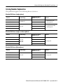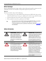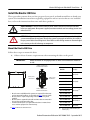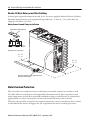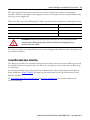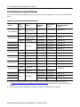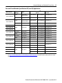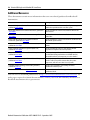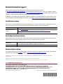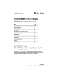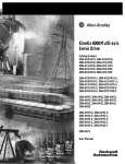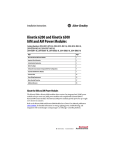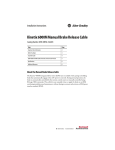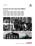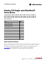
1
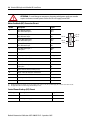
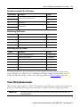
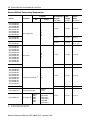
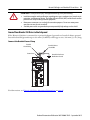
Installation Instructions
Kinetix 350 Single-axis EtherNet/IP
Servo Drives
Catalog Numbers 2097-V31PR0-LM, 2097-V31PR2-LM, 2097-V32PR0-LM,
2097-V32PR2-LM, 2097-V32PR4-LM, 2097-V33PR1-LM, 2097-V33PR3-LM,
2097-V33PR5-LM, 2097-V33PR6-LM, 2097-V34PR3-LM, 2097-V34PR5-LM,
2097-V34PR6-LM
Topic
Page
About the Kinetix 350 Drives
1
Important User Information
2
Catalog Number Explanation
3
Before You Begin
4
Safety Information
4
Install the Kinetix 350 Drive
5
Connector Data
7
Power Wiring Requirements
11
Motor Overload Protection
14
Circuit Breaker/Fuse Selection
15
Additional Resources
18
About the Kinetix 350 Drives
Kinetix® 350 single-axis EtherNet/IP servo drives provide an Ethernet-enabled solution for
applications with output power requirements in the range of 0.4…3.0 kW (2…12 A rms).
See the Kinetix 350 Single-axis EtherNet/IP Servo Drives User Manual, publication
2097-UM002, for detailed information on wire, apply power, troubleshoot,
and integrate with ControlLogix® or CompactLogix™ controller platforms.
2 Kinetix 350 Single-axis EtherNet/IP Servo Drives
Important User Information
Read this document and the documents listed in the additional resources section about installation, configuration, and operation of
this equipment before you install, configure, operate, or maintain this product. Users are required to familiarize themselves with
installation and wiring instructions in addition to requirements of all applicable codes, laws, and standards.
Activities including installation, adjustments, putting into service, use, assembly, disassembly, and maintenance are required to be
carried out by suitably trained personnel in accordance with applicable code of practice.
If this equipment is used in a manner not specified by the manufacturer, the protection provided by the equipment may be impaired.
In no event will Rockwell Automation, Inc. be responsible or liable for indirect or consequential damages resulting from the use or
application of this equipment.
The examples and diagrams in this manual are included solely for illustrative purposes. Because of the many variables and
requirements associated with any particular installation, Rockwell Automation, Inc. cannot assume responsibility or liability for actual
use based on the examples and diagrams.
No patent liability is assumed by Rockwell Automation, Inc. with respect to use of information, circuits, equipment, or software
described in this manual.
Reproduction of the contents of this manual, in whole or in part, without written permission of Rockwell Automation, Inc., is
prohibited.
Throughout this manual, when necessary, we use notes to make you aware of safety considerations.
WARNING: Identifies information about practices or circumstances that can cause an explosion in a hazardous
environment, which may lead to personal injury or death, property damage, or economic loss.
ATTENTION: Identifies information about practices or circumstances that can lead to personal injury or death,
property damage, or economic loss. Attentions help you identify a hazard, avoid a hazard, and recognize the
consequence.
IMPORTANT Identifies information that is critical for successful application and understanding of the product.
Labels may also be on or inside the equipment to provide specific precautions.
SHOCK HAZARD: Labels may be on or inside the equipment, for example, a drive or motor, to alert people that
dangerous voltage may be present.
BURN HAZARD: Labels may be on or inside the equipment, for example, a drive or motor, to alert people that
surfaces may reach dangerous temperatures.
ARC FLASH HAZARD: Labels may be on or inside the equipment, for example, a motor control center, to alert
people to potential Arc Flash. Arc Flash will cause severe injury or death. Wear proper Personal Protective
Equipment (PPE). Follow ALL Regulatory requirements for safe work practices and for Personal Protective
Equipment (PPE).
Rockwell Automation Publication 2097-IN008F-EN-P - September 2015
Kinetix 350 Single-axis EtherNet/IP Servo Drives 3
Catalog Number Explanation
This publication applies to the following Kinetix 350 drives.
Kinetix 350 Drives (single-phase)
Cat. No.
Continuous Output
Current A (0-pk)
Input Voltage
2097-V31PR0-LM
2.8
120/240V, 1 Ø
2097-V31PR2-LM
5.7
2097-V32PR0-LM
2.8
2097-V32PR2-LM
240V, 1 Ø
5.7
2097-V32PR4-LM
Features
• 120V Doubler mode
• Safe torque-off
• Integrated AC line filter
• Safe torque-off
11.3
Kinetix 350 Drives (single- or three-phase)
Cat. No.
Input Voltage
2097-V33PR5-LM
Features
2.8
2097-V33PR1-LM
2097-V33PR3-LM
Continuous Output
Current A (0-pk)
120V, 1 Ø
240V, 1 Ø
240V, 3 Ø
2097-V33PR6-LM
5.7
Safe torque-off
11.3
17.0
Kinetix 350 Drives (three-phase)
Cat. No.
Input Voltage
2097-V34PR3-LM
2097-V34PR5-LM
2097-V34PR6-LM
Continuous Output
Current A (0-pk)
Features
2.8
480V, 3 Ø
5.7
Safe torque-off
8.5
Rockwell Automation Publication 2097-IN008F-EN-P - September 2015
4 Kinetix 350 Single-axis EtherNet/IP Servo Drives
Before You Begin
Remove all packing material, wedges, and braces from within and around the components. After
unpacking, check the item nameplate catalog number against the purchase order.
Parts List
The Kinetix 350 drive ships with the following:
• General-purpose power input (IPD) header, back-up power (BP) header, shunt resistor
and DC bus (BC) header, motor power (MP) header, and safe-torque-off (STO) header
• A ground clamp that also provides strain relief for motor power cable
• These installation instructions, publication 2097-IN008
TIP
The connector kit for motor feedback (catalog number 2090-K2CK-D15M) is not provided.
Replacement connector sets (catalog number 2097-CONN1) are also available.
See the Kinetix Motion Accessories Specifications Technical Data, publication GMC-TD004, for
more information.
Safety Information
SHOCK HAZARD: Capacitors retain
charge for approximately 300 s after
power is removed. Disconnect
incoming power and wait at least 5
minutes before touching the drive.
Failure to observe this precaution
could result in severe bodily injury or
loss of life.
RISQUE DE CHOC: Les condensateurs
restent sous charge pendant environ 300
secondes après une coupure de courant.
Couper l’alimentation et patienter
pendant au moins 5 minutes avant de
toucher l’entraînement. Le non-respect
de cette précaution peut entraîner des
blessures corporelles graves ou la mort.
WARNING: The opening of
branch-circuit protective device can
be an indication that a fault has
been interrupted. To reduce the risk
of fire or electric shock, parts that
carry current and other components
of the controller must be examined
and replaced if damaged.
AVERTISSEMENT: Le déclenchement du
dispositif de protection du circuit de
dérivation peut être dû à une coupure qui
résulte d’un courant de défaut. Pour
limiter le risque d'incendie ou de choc
électrique, examiner les pièces porteuses
de courant et les autres éléments du
contrôleur et les remplacer s'ils sont
endommagés. En cas de grillage de
l'élément traverse par le courant dans un
relais de surcharge, le relais tout entier
doit être remplacé.
Rockwell Automation Publication 2097-IN008F-EN-P - September 2015
Kinetix 350 Single-axis EtherNet/IP Servo Drives 5
Install the Kinetix 350 Drive
These procedures assume that you have prepared your panel, and understand how to bond your
system. For installation instructions regarding equipment and accessories that are not included
here, refer to the instructions that came with those products.
SHOCK HAZARD: To avoid hazard of electrical shock, mount and wire of the Kinetix 350 drive
before you apply power. Once power is applied, connector terminals can have voltage present even
when not in use.
ATTENTION: Plan the installation of your system so that you can cut, drill, tap, and weld with the
system removed from the enclosure. Because the system is open-type construction, be careful to
keep any metal debris from falling into it. Metal debris or other foreign matter can become lodged
in the circuitry and result in damage to components.
Mount the Kinetix 350 Drive
Follow these steps to mount the drive.
1. Observe these clearance requirements when mounting the drive to the panel.
IMPORTANT
Mount the module in an upright position as shown. Do not mount the module on
its side.
25 mm (1.0 in.) Clearance
for Airflow and Installation
Drive
Cat. No.
A
Dimensions A
mm (in.)
2097-V31PR0-LM
185 (7.29)
2097-V31PR2-LM
3 mm (0.12 in.)
Side Clearance
3 mm (0.12 in.)
Side Clearance
2097-V32PR0-LM
2097-V32PR2-LM
230 (9.04)
2097-V32PR4-LM
2097-V33PR1-LM
25 mm (1.0 in.) Clearance
for Airflow and Installation
• More clearance and different hole patterns are required for side mount
and rear mount AC line filters. See the table and step 2 for more details.
• More clearance is required depending on the other accessory items
installed.
• More clearance is required for the cable and wires that are connected to
the top, front, and bottom of the drive.
• An extra 150 mm (6.0 in.) is required when the drive is mounted near
noise sensitive equipment or clean wire ways.
See page 6 for Kinetix 350 drive dimensions.
2097-V33PR3-LM
185 (7.29) (1)
2097-V33PR5-LM
2097-V33PR6-LM
2097-V34PR3-LM
230 (9.04)
185 (7.29) (1)
2097-V34PR5-LM
2097-V34PR6-LM
(1)
230 (9.04)
If you are using an AC line filter, add
50 mm (2 in.).
Rockwell Automation Publication 2097-IN008F-EN-P - September 2015
6 Kinetix 350 Single-axis EtherNet/IP Servo Drives
2. Mount the Kinetix 350 drive to the cabinet subpanel with M4 (#6-32) steel machine
screws torqued to 1.1 N•m (9.8 lb•in).
For catalog numbers 2097-V33PR1-LM, 2097-V33PR3-LM, 2097-V33PR5-LM,
2097-V34PR3-LM, and 2097-V34PR5-LM that use an AC line filter, refer to the AC
Line Filter Installation Instructions, publication 2097-IN003, for the subpanel
mounting hole pattern.
Kinetix 350 Drive Mounting Dimensions
Dimensions are in mm (in.).
A
5.0
(0.19)
7.1
(0.28)
30.8
(1.21)
9.7
(0.38)
182
(7.18)
190
(7.50)
238
(9.37)
6.6
(0.26)
2090-K2CK-D15M
Low-profile Connector Kit for Bulletin 61.0
2090 (flying-lead) Feedback Cable (2.40)
11.8
(0.46)
38.1
(1.5)
Ø 4.57
(0.18) 3x
B
More clearance below the connector kit is necessary to provide
the recommended cable-bend radius.
Dimensions mm (in.)
Cat. No.
Dimensions mm (in.)
Cat. No.
A
B
A
B
2097-V31PR0-LM
185.1 (7.29)
68.0 (2.68)
2097-V33PR3-LM
185.1 (7.29)
68.5 (2.70)
2097-V31PR2-LM
185.1 (7.29)
68.5 (2.70)
2097-V33PR5-LM
185.1 (7.29)
94.4 (3.72)
2097-V32PR0-LM
229.6 (9.04)
68.0 (2.68)
2097-V33PR6-LM
229.6 (9.04)
68.0 (2.68)
2097-V32PR2-LM
229.6 (9.04)
68.5 (2.70)
2097-V34PR3-LM
185.1 (7.29)
68.5 (2.70)
2097-V32PR4-LM
229.6 (9.04)
86.8 (3.42)
2097-V34PR5-LM
185.1 (7.29)
94.4 (3.72)
2097-V33PR1-LM
185.1 (7.29)
68.0 (2.68)
2097-V34PR6-LM
229.6 (9.04)
68.0 (2.68)
Rockwell Automation Publication 2097-IN008F-EN-P - September 2015
Kinetix 350 Single-axis EtherNet/IP Servo Drives 7
Connector Data
To identify the Kinetix 350 drive features and indicators, use this illustration.
Kinetix 350 Drive Features and Indicators
9
1
2
3
4
5
12
6
11
7
10
8
9
Top View
(2097-V33PR5-LM
Kinetix 350 drive is shown)
Item
Description
1
Data status indicator and diagnostic display
2
Memory module socket
3
Network status indicator
4
Module status indicator
5
Axis status indicator
6
Ethernet communication port (Port 1)
7
I/O (IOD) connector
8
Motor feedback (MF) connector
9
Ground Lug
10
Shunt resistor and DC bus (BC) connector
11
Back-up power (BP) connector
12
Display control push buttons (3)
13
Mains (IPD) connector
14
Motor power (MP) connector
15
Safe torque-off (STO) connector
Bottom View
(2097-V33PR5-LM
Kinetix 350 drive is shown)
14
13
15
Rockwell Automation Publication 2097-IN008F-EN-P - September 2015
8 Kinetix 350 Single-axis EtherNet/IP Servo Drives
Kinetix 350 Drive Connectors
Designator
Description
Connector
IPD
AC mains input power
4-position plug/header
PORT1
Ethernet communication port
RJ45 Ethernet
IOD
I/O
SCSI 50-pin high-density connector
MF
Motor feedback
15-pin high-density D-shell (male)
BP
Back-up power
2-pin quick-connect terminal block
BC
Shunt resistor and DC bus
7-pin quick-connect terminal block
MP
Motor power
6-pin quick-connect terminal block
STO
Safe torque-off (STO) terminal
6-pin quick-connect terminal block
Mains (IPD) Connector Pinout
IPD Designator
Description
Signal
L3
AC power in (3-phase models)
L3
L2
AC power in
L2
L1
AC power in
L1
PE
Protective earth (ground)
PE
Pin Orientation for 8-pin Ethernet Communication Port (port 1)
Port 1 Pin
Description
Signal
1
Transmit port (+) data terminal
+ TX
2
Transmit port (-) data terminal
- TX
3
Receive port (+) data terminal
+ RX
4
–
–
5
–
–
6
Receive port (-) data terminal
- RX
7
–
–
8
–
–
Rockwell Automation Publication 2097-IN008F-EN-P - September 2015
1
8
Kinetix 350 Single-axis EtherNet/IP Servo Drives 9
I/O (IOD) Connector Pinout
IOD Pin
Description
Signal
1…4
Reserved
–
5
Reserved
–
6
Reserved
–
7…25
Reserved (not used by Kinetix 350 drives)
–
26
± Overtravel, enable and home common
COM
27
Negative hardware overtravel
NEG_OT
28
Positive hardware overtravel
POS_OT
29
Drive enable
ENABLE
30
Home switch
HOME_SW
31…35
Reserved
–
36
Registration common
REG_COM
37…38
Reserved
–
39
Registration input
REG
40…42
Reserved
–
43
Brake release positive
BRAKE+
44
Brake release negative
BRAKE-
45…50
Reserved
–
1
26
25
50
Rockwell Automation Publication 2097-IN008F-EN-P - September 2015
10 Kinetix 350 Single-axis EtherNet/IP Servo Drives
ATTENTION: To avoid damage to components, determine which power supply your encoder
requires and connect encoder power to either the 5V or 9V supply, but not both.
Motor Feedback (MF) Connector Pinout
MF Pin
Description(1)
Signal
1
Sine differential input+
AM+ differential input+
SIN+
AM+
2
Sine differential inputAM- differential input-
SINAM-
Cosine differential input+
BM+ differential input+
COS+
BM+
4
Cosine differential inputBM- differential input-
COSBM-
5
Data differential input +
Index pulse+
DATA+
IM+
6
Common
ECOM
7
Encoder power (+9V)
EPWR_9V (1)
8
Single-ended 5V Hall effect commutation
S3
9
Reserved
–
10
Data differential input Index pulse-
DATAIM-
11
Motor thermal switch (normally closed) (2)
TS
12
Single-ended 5V Hall effect commutation
S1
13
Single-ended 5V Hall effect commutation
S2
14
Encoder power (+5V)
EPWR_5V (1)
15
Reserved
–
3
(1)
(2)
Pin 15
Pin 11
Pin 6
Determine which power supply your encoder requires and connect to only the specified supply. Do not make connections to both.
Not applicable unless motor has integrated thermal protection.
Control Power Back-up (BP) Pinout
BP Designator
Description
Signal
+24V
Positive 24V DC
+24V DC
-24V
24V DC power supply return
Return
Rockwell Automation Publication 2097-IN008F-EN-P - September 2015
Pin 10
Pin 5
Pin 1
Kinetix 350 Single-axis EtherNet/IP Servo Drives 11
Shunt Resistor and DC Bus (BC) Pinout
BC Designator
Description
Signal
+
+
Positive DC bus and shunt resistor
+
SH
+
Shunt resistor
SH
–
–
Negative DC bus
–
–
Motor Power (MP) Pinout
MP Designator
Description
Signal
PE
Protective earth (ground)
PE
W
Motor power out
W
V
Motor power out
V
U
Motor power out
U
Safe Torque-off (STO) Pinout
STO Pin
Description
Signal
1
+24V DC output from the drive
+24V DC control
2
+24V DC output common
Control COM
3
Safety status
Safety Status
4
Safety input 1 (+24V DC to enable)
Safety Input 1
5
Safety common
Safety COM
6
Safety input 2 (+24V DC to enable)
Safety Input 2
The Kinetix 350 drive ships with safe torque-off enabled. To obtain motion, connect safe
torque-off inputs to a safety circuit, or install motion-allowed jumpers. See the Kinetix 350
Single-axis EtherNet/IP Servo Drive User Manual, publication 2097-UM002, for details.
Power Wiring Requirements
Wire must be copper with 75 °C (167 °F) minimum rating. The phase connections of main AC
power are arbitrary and earth-ground connection is required for safe and proper operation.
IMPORTANT
The National Electrical Code and local electrical codes take precedence over the values and
methods provided.
Rockwell Automation Publication 2097-IN008F-EN-P - September 2015
12 Kinetix 350 Single-axis EtherNet/IP Servo Drives
Kinetix 350 Drive Power-wiring Requirements
Recommended
Wire Size
mm2 (AWG)
Strip
Length
mm (in.)
Torque
Value
N•m (lb•in)
2.5 (14)
7 (0.28)
0.5 (4.5)
2097-V32PR4-LM
2097-V33PR5-LM
4.0 (12)
7 (0.28)
0.5 (4.5)
2097-V31PR2-LM
2097-V33PR6-LM
6.0 (10)
7 (0.28)
0.56…0.79
(5.0…7.0)
2.5 (14)
7 (0.28)
0.5 (4.5)
4.0 (12)
7 (0.28)
0.5 (4.5)
2.5 (14)
7 (0.28)
0.5 (4.5)
4.0 (12)
7 (0.28)
0.5 (4.5)
1.5 (16)
6 (0.25)
0.5 (4.5)
Terminals
Cat. No.
Description
Pin
2097-V31PR0-LM
2097-V32PR0-LM
2097-V32PR2-LM
2097-V33PR1-LM
2097-V33PR3-LM
2097-V34PR3-LM
2097-V34PR5-LM
2097-V34PR6-LM
2097-V31PR0-LM
2097-V32PR0-LM
2097-V32PR2-LM
2097-V32PR4-LM
2097-V33PR1-LM
2097-V33PR3-LM
2097-V33PR5-LM
2097-V34PR3-LM
2097-V34PR5-LM
2097-V34PR6-LM
2097-V31PR2-LM
Signal
L3
L2
L1
PE
Mains input power
PE
W
V
U
Motor power
2097-V33PR6-LM
2097-V31PR0-LM
2097-V32PR0-LM
2097-V32PR2-LM
2097-V32PR4-LM
2097-V33PR1-LM
2097-V33PR3-LM
2097-V33PR5-LM
2097-V34PR3-LM
2097-V34PR5-LM
2097-V34PR6-LM
2097-V31PR2-LM
Shunt resistor and DC bus
(1)
+
+
SH
–
–
2097-V33PR6-LM
2097-V3xPRx-LM
2097-V3xPRx-LM
(1)
(2)
Control back-up power
Safe torque-off
STO-1 (2)
STO-2 (2)
STO-3
STO-4
STO-5
STO-6
+24V DC
Return
+24V DC Control
Control COM
Safety Status
Safety Input 1
Safety COM
Safety Input 2
Use only for shunt resistor connection.
Use only for bypassing the STO circuit.
Rockwell Automation Publication 2097-IN008F-EN-P - September 2015
Kinetix 350 Single-axis EtherNet/IP Servo Drives 13
ATTENTION: To avoid personal injury and equipment damage, verify the following:
• Installation complies with specifications regarding wire types, conductor sizes, branch circuit
•
•
protection, and disconnect devices. The National Electrical Code (NEC) and local codes outline
provisions for safely installing electrical equipment.
Motor power connectors are used only for connection purposes. Do not use motor power
connectors to turn the unit on and off.
Shielded power cables are grounded to prevent potentially high voltages on the shield.
Ground Your Kinetix 350 Drive to the Subpanel
If the Kinetix 350 drive is mounted on a painted subpanel, ground to a bonded cabinet ground
bus with a braided ground strap or 4.0 mm2 (12 AWG) solid-copper wire, 100 mm (3.9 in.) long.
Connect the Braided Ground Strap
Braided
Ground Strap
Ground Stud
Bonded Cabinet
Ground Bus
Ground Grid or Power
Distribution Ground
For dimensions, see Kinetix 350 Drive Mounting Dimensions on page 6.
Rockwell Automation Publication 2097-IN008F-EN-P - September 2015
14 Kinetix 350 Single-axis EtherNet/IP Servo Drives
Kinetix 350 Drive Motor-power Wire Shielding
A motor-power ground clamp and two #6-32 x 1 screws are supplied with the Kinetix 350 drive.
Install the supplied motor-power ground clamp within 50…75 mm (2…3 in.) of the drive by
using the two #6-32 x 1 screws.
Motor Power Ground Clamp Installation
Motor Power Ground Clamp
25
(1.0)
34.0
(1.34)
12.7
(0.50)
Dimensions are in mm (in.).
50…75
(2…3)
50…75
(2…3)
If panel is painted, remove paint to provide
metal-to-metal contact.
Motor Overload Protection
This servo drive uses solid-state motor overload protection that operates in accordance with
UL 508C. Motor overload protection algorithms (thermal memory) that can predict actual
motor temperature are based on operating conditions as long as control power is continuously
applied. However, when control power is removed, thermal memory is not retained.
This drive also provides an input for an external temperature sensor or thermistor device, which
is embedded in the motor, to support the UL requirement for motor overload protection.
Rockwell Automation Publication 2097-IN008F-EN-P - September 2015
Kinetix 350 Single-axis EtherNet/IP Servo Drives 15
The drive supports some motors that do not contain temperature sensors or thermistors;
therefore, motor overload protection against excessive consecutive motor overloads followed by
power-up is not supported.
This servo drive meets the following UL 508C requirements for solid-state overload protection.
Motor Overload Protection Trip Point
Value
Ultimately
100% overload
Within 8 minutes
200% overload
Within 20 seconds
600% overload
ATTENTION: Avoid overheat damage to your motor from excessive and successive motor
overload faults by following the motor and drive-combination wiring diagram that is
provided in the user manual.
See your servo drive user manual for the interconnect diagram that illustrates the wiring between
your motor and drive.
Circuit Breaker/Fuse Selection
The Kinetix 350 drives use internal solid-state motor short-circuit protection. When protected
by suitable branch circuit protection, the drives are rated for use on a circuit that can deliver up
to 100,000 A.
See Kinetix 350 Drive Power Specifications in Kinetix Servo Drives Specifications Technical
Data, publication GMC-TD003 for input current and inrush current specifications for your
Kinetix 350 drive.
See Circuit Breaker/Fuse Specifications on page 16 and page 17 for recommended circuit
breakers and fuses.
Rockwell Automation Publication 2097-IN008F-EN-P - September 2015
16 Kinetix 350 Single-axis EtherNet/IP Servo Drives
Circuit Breaker/Fuse Specifications
These fuses and Allen-Bradley circuit breakers are recommended for use with 2097-VxxPRx-LM
drives.
Input Power Circuit-protection Specifications
Cat. No.
Drive
Voltage
Phase
Fuses
(Bussmann)
Cat. No.
Miniature CB (1)
Cat. No.
Motor Protection CB, (1) (2)
Self-protected CMC
Cat. No.
120V
Single-phase
(voltage doubler)
KTK-R-20 (20A)
1489-M1C200
140M-D8E-C20
120/240V
Single-phase
KTK-R-10 (10A)
1489-M1C100
140M-C2E-C10
120V
Single-phase
(voltage doubler)
KTK-R-30 (30A)
1489-M1C300
140M-F8E-C32
120/240V
Single-phase
KTK-R-20 (20A)
1489-M1C200
140M-D8E-C20
KTK-R-20 (20A)
1489-M1C150
140M-D8E-C16
1489-M1C200
140M-D8E-C20
2097-V31PR0-LM
2097-V31PR2-LM
2097-V32PR0-LM
2097-V32PR2-LM
240V
Single-phase
KTK-R-20 (20A)
KTK-R-30 (30A)
1489-M1C300
140M-F8E-C32
120/240V
Single-phase
KTK-R-20 (20A)
1489-M1C200
140M-D8E-C20
240V
Three-phase
KTK-R-15 (15A)
1489-M3C150
140M-D8E-C16
120/240V
Single-phase
KTK-R-20 (20A)
1489-M1C200
140M-D8E-C20
240V
Three-phase
KTK-R-15 (15A)
1489-M3C150
140M-D8E-C16
120/240V
Single-phase
KTK-R-30 (30A)
1489-M1C300
140M-F8E-C32
240V
Three-phase
KTK-R-20 (20A)
1489-M3C200
140M-D8E-C20
120/240V
Single-phase
LPJ-40SP (40A)
Class J
N/A
240V
Three-phase
KTK-R-30 (30A)
1489-M3C300
KTK-R-10 (10A)
1489-M3C100
140M-C2E-C10
KTK-R-10 (10A)
1489-M3C100
140M-C2E-C10
KTK-R-20 (20A)
1489-M3C200
140M-D8E-C20
2097-V32PR4-LM
2097-V33PR1-LM
2097-V33PR3-LM
2097-V33PR5-LM
2097-V33PR6-LM
2097-V34PR3-LM
2097-V34PR5-LM
2097-V34PR6-LM
480V
Three-phase
140M-F8E-C32
(1) Bulletin 1492 and 1489 circuit protection devices have lower short-circuit current ratings than Bulletin 140M devices.
See http://ab.rockwellautomation.com/allenbradley/productdirectory.page? for product literature with specific short-circuit
ratings.
(2) For UL applications, Bulletin 140M devices are applied as self-protected combination motor controllers.
Rockwell Automation Publication 2097-IN008F-EN-P - September 2015
Kinetix 350 Single-axis EtherNet/IP Servo Drives 17
Fuse and Circuit Breaker Specifications IEC (non-UL) Applications
Drive Cat. No.
Miniature CB (1)
Cat. No.
Drive
Voltage
Phase
120V
Single-phase
(voltage doubler)
1489-M1C200
1492-SPM1D200
140M-D8E-C20
120/240V
Single-phase
1489-M1C100
1492-SPM1D100
140M-C2E-C10
120V
Single-phase
(voltage doubler)
1489-M1C300
1492-SPM1D300
140M-F8E-C32
120/240V
Single-phase
1489-M1C200
1492-SPM1D200
140M-D8E-C20
1489-M1C150
1492-SPM1D150
140M-D8E-C16
1489-M1C200
1492-SPM1D200
140M-D8E-C20
2097-V31PR0-LM
2097-V31PR2-LM
2097-V32PR0-LM
2097-V32PR2-LM
Motor Protection CB
Cat. No.
240V
Single-phase
1489-M1C300
1492-SPM1D320
140M-F8E-C32
120/240V
Single-phase
1489-M1C200
1492-SPM1D200
140M-D8E-C20
240V
Three-phase
1489-M3C150
1492-SPM3D150
140M-D8E-C16
120/240V
Single-phase
1489-M1C200
1492-SPM1D200
140M-D8E-C20
240V
Three-phase
1489-M3C150
1492-SPM3D150
140M-D8E-C16
120/240V
Single-phase
1489-M1C300
1492-SPM1D300
140M-F8E-C32
240V
Three-phase
1489-M3C200
1492-SPM3D200
140M-D8E-C20
120/240V
Single-phase
N/A
N/A
240V
Three-phase
1489-M3C300
1492-SPM3D300
1489-M3C100
1492-SPM3D100
140M-C2E-C10
1489-M3C100
1492-SPM3D100
140M-C2E-C10
1489-M3C200
1492-SPM3D200
140M-D8E-C20
2097-V32PR4-LM
(1)
2097-V33PR1-LM
2097-V33PR3-LM
2097-V33PR5-LM
2097-V33PR6-LM
140M-F8E-C32
2097-V34PR3-LM
2097-V34PR5-LM
2097-V34PR6-LM
480V
Three-phase
(1) Bulletin 1492 and 1489 circuit protection devices have lower short-circuit current ratings than Bulletin 140M devices.
See http://ab.rockwellautomation.com/allenbradley/productdirectory.page? for product literature with specific short-circuit
ratings.
Rockwell Automation Publication 2097-IN008F-EN-P - September 2015
18 Kinetix 350 Single-axis EtherNet/IP Servo Drives
Additional Resources
These documents contain more information that concerns related products from Rockwell
Automation.
Resource
Description
Kinetix 350 Single-axis EtherNet/IP Servo Drives User Manual,
publication 2097-UM002
Provides information on how to install, configure, start up, and
troubleshoot your Kinetix 350 servo drive system.
Kinetix 300 Shunt Resistor Installation Instructions, publication
2097-IN002
Provides information on how to install and wire Kinetix 300
shunt resistors.
Kinetix 300 AC Line Filter Installation Instructions, publication
2097-IN003
Provides information on how to install and wire the Kinetix 300
AC line filter.
Kinetix 300 I/O Terminal Expansion Block Installation
Instructions, publication 2097-IN005
Provides information on how to install and wire the Kinetix 300
I/O terminal expansion block.
Kinetix 300 Memory Module Installation Instructions,
publication 2097-IN007
Provides information on how to install the Kinetix 300 memory
module.
Kinetix 300 Memory Module Programmer Quick Start,
publication 2097-QS001
Provides information on the use of the memory module
programmer to duplicate the memory module.
Kinetix Servo Drives Specifications Technical Data,
publication GMC-TD003
Provides product specifications for Kinetix Integrated Motion
over EtherNet/IP, Integrated Motion over SERCOS interface,
EtherNet/IP network, and component servo drive families.
Kinetix Motion Accessories Specifications Technical Data,
publication GMC-TD004
Provides product specifications for Bulletin 2090 motor and
interface cables, low-profile connector kits, drive power
components, and other servo drive accessory items.
Industrial Automation Wiring and Grounding Guidelines,
publication 1770-4.1
Provides general guidelines for installing a Rockwell
Automation industrial system.
Product Certifications website, http://www.ab.com
Provides declarations of conformity, certificates, and other
certification details.
You can view or download publications at http://www.rockwellautomation.com/literature. To
order paper copies of technical documentation, contact your local Allen-Bradley distributor or
Rockwell Automation sales representative.
Rockwell Automation Publication 2097-IN008F-EN-P - September 2015
Kinetix 350 Single-axis EtherNet/IP Servo Drives 19
Notes:
Rockwell Automation Publication 2097-IN008F-EN-P - September 2015
Rockwell Automation Support
Rockwell Automation provides technical information on the Web to assist you in using its products.
At http://www.rockwellautomation.com/support you can find technical and application notes, sample code, and links to software
service packs. You can also visit our Support Center at https://rockwellautomation.custhelp.com/ for software updates, support chats
and forums, technical information, FAQs, and to sign up for product notification updates.
In addition, we offer multiple support programs for installation, configuration, and troubleshooting. For more information, contact
your local distributor or Rockwell Automation representative, or visit http://www.rockwellautomation.com/services/online-phone.
Installation Assistance
If you experience a problem within the first 24 hours of installation, please review the information that's contained in this manual.
You can also contact a special Customer Support number for initial help in getting your product up and running.
United States or Canada
1.440.646.3434
Outside United States or
Canada
Use the Worldwide Locator at
http://www.rockwellautomation.com/rockwellautomation/support/overview.page, or contact your
local Rockwell Automation representative.
New Product Satisfaction Return
Rockwell Automation tests all of its products to help ensure that they are fully operational when shipped from the manufacturing
facility. However, if your product is not functioning and needs to be returned, follow these procedures.
United States
Contact your distributor. You must provide a Customer Support case number (call the phone number
above to obtain one) to your distributor to complete the return process.
Outside United States
Please contact your local Rockwell Automation representative for the return procedure.
Documentation Feedback
Your comments will help us serve your documentation needs better. If you have any suggestions on how to improve this document,
complete this form, publication RA-DU002, available at http://www.rockwellautomation.com/literature/.
Allen-Bradley, CompactLogix, ControlLogix, Kinetix, Rockwell Software, and Rockwell Automation are trademarks of Rockwell
Automation, Inc.
Trademarks not belonging to Rockwell Automation are property of their respective companies.
Rockwell Otomasyon Ticaret A.Ş., Kar Plaza İş Merkezi E Blok Kat:6 34752 İçerenköy, İstanbul, Tel: +90 (216) 5698400
Publication 2097-IN008F-EN-P - September 2015
Supersedes Publication 2097-IN008E-EN-P - December 2014
Copyright © 2015 Rockwell Automation, Inc. All rights reserved. Printed in the U.S.A.
(13496814)