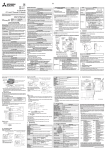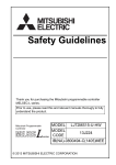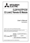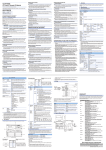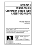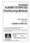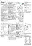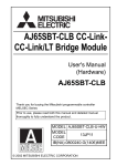
1
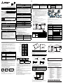
Side
B
Electromagnetic Compatibility
Standards (EMC)
Thank you very much for purchasing this product.
Please read this manual thoroughly before starting to use the product and
handle the product properly.
User’s Manual
CL1PAD1
JY997D04601F
April 2015
●SAFETY PRECAUTIONS●
(Read these precautions before using)
Please read this manual carefully and pay special attention to safely in order
to handle this product properly. Also pay careful attention to safely and handle
the module properly.
These precautions apply only to Mitsubishi equipment. Refer to the user’s
manual of the CPU module to use for a description of the PLC system safety
precautions.
These ●SAFETY PRECAUTIONS● classify the safety precautions into two
categories: "WARNING" and "CAUTION".
Procedures which may lead to a dangerous condition
and cause death or serious injury if not carried out
properly.
Procedures which may lead to a dangerous condition
and cause superficial to medium injury, or physical
damage only, if not carried out properly.
Depending on circumstances, procedures indicated by
may also
be linked to serious results.
In any case, it is important to follow the directions for usage.
Store this manual in a safe place so that you can take it out and read it
whenever necessary. Always forward it to the end user.
[DESIGN PRECAUTIONS]
• Make sure to shut down all phases of the power supply outside the module
before starting the installation or wiring work. If all phases are not shut down,
electrical shock or product damage may be caused.
• Confirm the rated voltage and the terminal arrangement of the power
adapter, then correctly wire the power adapter.
If a power supply not conforming to the specification rating is connected or
the power adapter is wired incorrectly, fire, failure or malfunction may occur.
• Tighten the terminal screws within the specified torque range.
If the terminal screws are insufficiently tightened, fire or malfunction may occur.
If the terminal screws are excessively tightened, the screws may be
damaged, and the module may short-circuit, equipment failures, or malfunction.
• Make sure that foreign objects such as cutting and wire chips do not enter the
power adapter.
Fire, failure or malfunction may be caused by the foreign objects.
• Attach a warning label (hazard symbol 417-IEC-5036) concerning electric
shock to the panel.
[STARTING AND MAINTENANCE PRECAUTIONS]
• Do not touch the terminals while the power is being supplied.
Electrical shock or malfunction may be caused by such touching.
• Shut down all phases of the power supply outside the power adapter before
cleaning or tightening the terminal screws.
If all phases are not shut down, the power adapter may fail or malfunction.
• Do not disassemble or modify the power adapter.
Failure, malfunction, injury or fire may be caused by disassembly or modification.
• The power adapter case is made of resin. Do not drop it. Do not apply strong
impact to it.
The power adapter may be damaged by dropping or strong impact.
• Shut down all phases of the power supply outside the power adapter before
attaching or removing the power adapter to/from the panel.
If all phases are not shut down, the power adapter may fail or malfunction.
[DISPOSAL PRECAUTIONS]
Name
Remark
Compliance with all relevant aspects of the
standard.
(Radiated Emissions, Conducted
EN61131-2: 2007
Emissions, Radiated electromagnetic field,
Programmable controllers
Fast transient burst, Electrostatic
-Equipment requirements and tests
discharge, High-energy surge, Voltage
drops and interruptions, Conducted RF
and Power frequency magnetic field)
For more details please contact the local Mitsubishi Electric sales site.
• Notes for compliance to EMC LVD regulation.
It is necessary to install the CL1 series module in a shielded metal control panel.
• Do not bind the control cable and the flat cable dedicated to CC-Link/LT
together with the main circuit and the power cable. Keep such cables far
from the main circuit and the power cable. Assure a distance of 100mm
(3.94") or more.
Otherwise, malfunction may be caused by noise.
• Use the power adapter without applying any force on the connector for
CC-Link/LT interface and the flat cable dedicated to CC-Link/LT.
Otherwise, such cables may be broken or fail.
Outline of Product
• When disposing of the product, treat it as an industrial waste.
Power terminal
Status indicator LED
3.
External connection
method
4.
=
LINK connector
2-φ4.5 mounting hole
(M4 mounting screw)
• Authorized Representative in the European Community:
Mitsubishi Electric Europe B.V.
Gothaer Str. 8, 40880 Ratingen, Germany
+
Total current consumption
of I/O equipment (such
as sensors) (to which
power is supplied via
communication cable)*1
Name
Status
indicator LED
-25 to 75°C (-13 to 167°F)
5 to 95%RH: Dew condensation shall not be
allowed.
5 to 95%RH: Dew condensation shall not be
allowed.
Terminal arrangement
LINK/POWER connector
Interface
Vibration
resistance (*1)
POWER
Lit while the power is supplied
DB
DA
24G
LINK/POWER DB
connector
DA
+24V
For communication
For communication
Power supply for communication (-)
For communication
For communication
Power supply for communication (+)
Acceleration Half amplitude
−
10 to 57Hz
0.075mm
10 times in
each of X, Y
Continuous vibration is present
and Z
Frequency Acceleration Half amplitude directions
(80 min)
10 to 57Hz
0.035mm
−
57 to 150Hz
9.8m/s2
−
57 to 150Hz
4.9m/s2
−
Impact resistance (*1) 147 m/s2, 3 times in each of X, Y and Z directions
Operating
atmosphere
Corrosive gas should not be present.
Operating altitude
2,000m(6561'8") or less (*2)
Installation place
Inside control panel
Over-voltage
category
ΙΙ or less (*3)
Degree of
contamination
2 or less (*4)
7.
Installation
Number of
sweep
times
Intermittent vibration is present
Description
LINK
connector
1000
(3280'10")
560
(1837'3")
Outside Dimensions
Removal
Unit: mm(inches)
1)
Center of DIN rail
4)
66(2.60")
90(3.55")
100
(328'1")
Applicable DIN
rail
TH35-7.5Fe and TH35-7.5AI
5.3 Direct installation
1.0
(3'3")
0.1
(0'4")
Screw-tighten the power adapter by tightening M4 screws to the upper and
lower mounting holes (two holes in all) provided in the power adapter.
Install the module so that the clearance of 1 to 2mm (0.04" to 0.08") is assured
for each module.
Applicable screw
0.1
1.0
Current consumption [A]
Maximum
distance (m)
+ Constant: 11
×
Constant
: 0.06
5.4 Crimp-style terminal
For the I/O wiring, use crimp-style terminals of the following dimensions.
Maximum
distance
Total current
consumption
Total current
consumption (A)
6.2 mm (0.24" )
or less
6.2 mm (0.24" )
or less
≤ 3.6V
Furthest station from the power adapter
Total current
consumption of each
module in CC-Link/LT
system
+
φ 3.2 (0.13")
φ 3.2 (0.13")
×
Mass (Weight): 0.26kg (0.58lbs)
M4 × 0.7mm(0.03") × 16mm(0.63") or more
(Tightening torque range: 0.78 to 1.08 N⋅m)
2) Selection based on the calculation formula
=
2 - φ4.5(0.18") mounting
hole (M4 mounting screw)
10
One power adapter is allowed within the range shown in the graph above.
Voltage
drop (V)
3)
2)
10
(32'10")
75(2.96") ± 0.2(0.01")
Maximum cable length [m(inches)]
10(0.40")
Terminal screw
When wiring two cables to one terminal
Crimp-style
terminal
Terminal screw
Crimp-style
terminal
Total current consumption of I/O
equipment (such as sensors)
(to which power is supplied via
communication cable)*1
Terminal
*1 Some remote I/O modules for CC-Link/LT supply the power for I/O via the flat
cable dedicated to CC-Link/LT.
For the details, refer to the instruction manual of each remote I/O module.
The simplified graph and the calculation formula concerning voltage drop
calculations may not be accurate depending on the ambient temperature
and the number of used connectors dedicated to CC-Link/LT.
If the driving voltage (20.4V) cannot be assured in a used remote I/O
module, add another power adapter.
Installation
The power adapter can be installed to a DIN rail or directly installed with screws.
Each installation procedure is described below.
≤ 5A
Specification
0 to 55°C (32 to 131°F)
Frequency
Standards with which this product complies
Type : Programmable Controller (Open Type Equipment)
Models : Products manufactured:
from November 1st, 2002 to April 30th, 2006 are compliant with
EN61000-6-4 and EN61131-2:1994+A11:1996+A12:2000
after May 1st, 2006 are compliant with EN61131-2:2007
Electromagnetic Compatibility
Remark
Standards (EMC)
EN61000-6-4:2001
Compliance with all relevant aspects of the
Electromagnetic compatibility
standard.
-Generic standards - Emission
(Radiated Emissions and Mains Terminal
standard for Industrial environment Voltage Emissions)
Compliance with all relevant aspects of the
EN61131-2:1994/A11:1996/A12:2000
standard.
Programmable controllers
(RF Immunity, Fast transients, ESD and
-Equipment requirements and tests
Damped oscillatory wave)
5.
4.1.1 Current consumption calculation
Total current
consumption of
each module in
CC-Link/LT system
Ambient storage
temperature
Ambient operating
humidity
Ambient storage
humidity
When wiring one cable to one terminal
4.1 System power calculation method
Current
consumption
in CC-Link/LT
system
Item
●Notification of CE marking●
Construction Cautions
Installation of power adapters
At least one power adapter is required per CC-Link/LT system.
When constructing the system using only one power adapter, the following
three conditions should be satisfied.
If the following two conditions are not satisfied, use of two or more power
adapters in constructing the system.
• The current capacity of the power adapter is 5A, therefore, total current
consumption should be an equivalent to or less than 5 A.
• In order to operate the system in stable status, the voltage drop should be
equivalent to or less than 3.6 V.
• The minimum operating voltage of each module connected to the power
adapter is 20.4 V, therefore, supply voltage subtracted by the voltage drop
should be equivalent to or more than 20.4 V.
1
Specifications
Ambient working
temperature
This notification does not guarantee that an entire mechanical module produced
in accordance with the contents of the notification comply with the following
standards. Compliance to EMC standards of the entire mechanical module
should be checked by the user / manufacturer.
Attention
Depends on the connected model (28.8V DC max.).
5.0A
[Use the power adapter in the range in which the
total current consumption of each unit does not
exceed the maximum rated current while the power
is supplied (except the period immediately after the
power is turned on).]
10MΩ between the external terminals as a whole
and the ground terminal by 500V DC megger
Supplies power from outside to power adapter:
3 points (M3 screws) on terminal block
Communication line/module power supply module
Compatible with flat cable dedicated to CC-Link/LT
Connector (with 4 pins) dedicated to CC-Link/LT × 2
1
1) LINK connector
2) LINK/POWER connector
24G
Insulation resistance
External
power
supply
DIN rail installation groove
• During transportation avoid any impact as the module is a precision
instrument. Doing so could cause trouble in the module.
• If is necessary to check the operation of module after transportation, in case
of any impact damage.
Specification
Max. rated current
External
power
supply
1) General specifications
2) Performance specifications
Item
Power adapter
LINK/POWER connector:
Executes communication, and supplies the power to the CC-Link/LT
system.
Name of Each Part
2.1 Name of each part and assignment
*2 The module cannot be used in an environment pressurized above the
atmospheric pressure which can be generated around the altitude of 0 m.
If the module is used in such an environment, it may fail.
*3 It indicates in which wiring area from the public wiring net to the
mechanical module inside the site the equipment is assumed to be
connected.
The category ΙΙ applies, for example, to equipment whose power is
supplied from a fixed facility.
The surge-resistant voltage of equipment whose rating is up to 300V is
2,500V.
*4 This index indicates the degree of generation of conductive substances in
the environment in which the module is used. The degree of contamination
2 indicates that contamination is caused by generation of only nonconductive substances.
In this degree, however, temporar y conduction may be caused by
accidental condensation.
Voltage input range
2)
Power adapter
2.
1) Selection based on the simplified graph
*1 The criterion is shown in IEC61131-2.
1)
2)
LINK connector:
Executes only communication (does not supply power).
Used when two or more power adapters are used in the CC-Link/LT
system.
+24V
• Use the power adapter within an environment described by the general
specifications in this manual.
If the power adapter is used in any environment outside the range for the
general specifications, electrical shock, fire, malfunction, product
damage or product deterioration may occur.
• Do not directly touch the conductive area of the power adapter.
Malfunction or damage of the power adapter may be caused by such
touching.
• Securely fix the power adapter with DIN rail or mounting screws.
Securely tighten the mounting screws within the specified torque range.
If the screws are insufficiently tightened, the power adapter may drop,
short-circuit or malfunction.
If the screws are excessively tightened, the screws may be damaged,
and the power adapter may drop or short-circuit.
• Install the power adapter on to a flat surface.
If the mounting surface is concave and/or convex, and if excessive force
is applied on the PC board, nonconformity may occur.
1)
This product is a power adapter connected to CC-Link/LT.
This product supplies 24V DC power from an external power supply to the
CC-Link/LT system.
At least one power adapter is required per CC-Link/LT system.
• This product is designed for use in industrial applications.
Note
[INSTALLATION PRECAUTIONS]
2.2 Handling of LINK connector and LINK/POWER connector
Master module
*1 Zone defined in EN61131-2
Separation defined in EN61131-2 for EMC LVD regulation decided
depending on condition in industrial setting.
Zone C = Factory mains which is isolated from public mains by dedicated
transformers.
Zone B = Dedicated power distribution which is protected by secondary
surge pro tection. (300V or le ss in the ra ted vo ltage is
assumed.)
Zone A = Local power distribution which is isolated from dedicated power
distribution by AC/DC converters, isolation transformers, etc.
(120V or less in the rated voltage is assumed.)
• When the following models use the CC-Link/LT power adapter model
(CL1PAD1), a power line connecting to the external power supply terminal of
the CL1PAD must be 30m(98’5’’) or less.
- CL2AD4-B
- CL2DA2-B
[TRANSPORTATION AND MAINTENANCE PRECAUTIONS]
• Depending on a failure in the remote I/O module, the output may
become the ON or OFF status. For output signals which can lead to a
severe accident, install a circuit monitoring them outside the module.
Power terminal 24G
• Use this product in Zone A*1 as defined in EN61131-2.
1.
Description
Supplies power from outside to
power adapter.
Input voltage: 28.8V DC or less
(depending on connected model)
Rated input current: 5.0 A
(Use a proper external power
supply under consideration of initial
current of remote I/O modules.)
+24V
CO
MM
.
CL1PAD1
Power Adapter Model
MODEL
MANUAL Number
Date
[WIRING PRECAUTIONS]
ENGLISH
43(1.70")
JAPANESE
CO
MM
.
B
85(3.35")
A
Side
5(0.20")
Side
5.1 Installation direction
*1 Some remote I/O modules for CC-Link/LT supply the power for I/O via the
flat cable dedicated to CC-Link/LT.
For the details, refer to the instruction manual of each remote I/O module.
Do not install the power adapter on the floor surface, the ceiling surface or in the
vertical direction. If the power adapter is installed on such a surface or in such a
direction, its temperature may rise.
Make sure to install the power adapter on the wall horizontally.
4.1.2 Voltage drop
5.2 Installation to DIN rail
Calculate the voltage drop based on the simplified graph or the calculation
formula. (supply voltage: 24V DC, ambient temperature: 20°C)
Align the upper DIN rail installation groove in the power adapter with the DIN rail
1), and press the power adapter in that status 2).
When removing the power adapter, pull downward the hook for installation to
DIN rail 3), then remove the power adapter 4)
Terminal
• Tighten the terminal screws (M3 screws) on the terminal block with a
tightening torque of 0.42 to 0.58 N • m. Do not tighten terminal screws
exceeding the specified torque. Failure to do so may cause short circuit,
equipment failures, or malfunctions.
• RAV1.25-3
Applicable crimp- • V1.25-3 (manufactured by JST Mfg. Co., Ltd.)
style terminal
• 1.25-3 and TG1.25-3
(manufactured by NICHIFU Co., Ltd.)
Applicable wire
size
6.
0.3 to 1.25 mm2
Power Wiring
LINK
Connector for
CC-Link/LT
interface - DA
DB
--
LINK/POWER
Connector for
CC-Link/LT interface
+24V
DA
DB
24G
Power adapter
External power supply
24V DC, 5A or less
Internal
circuit
+24V
24G
+
Grounding
(100Ω or less)
Terminal block for
power adapter
This manual confers no industrial property rights or any rights of any other kind, nor
does it confer any patent licenses. Mitsubishi Electric Corporation cannot be held
responsible for any problems involving industrial property rights which may occur as
a result of using the contents noted in this manual.
Warranty
Mitsubishi will not be held liable for damage caused by factors found not to be the
cause of Mitsubishi; machine damage or lost profits caused by faults in the Mitsubishi
products; damage, secondary damage, accident compensation caused by special
factors unpredictable by Mitsubishi; damages to products other than Mitsubishi
products; and to other duties.
For safe use
• This product has been manufactured as a general-purpose part for general
industries, and has not been designed or manufactured to be incorporated in a
device or system used in purposes related to human life.
• Before using the product for special purposes such as nuclear power, electric power,
aerospace, medicine or passenger movement vehicles, consult with Mitsubishi.
• This product has been manufactured under strict quality control. However when
installing the product where major accidents or losses could occur if the product
fails, install appropriate backup or failsafe functions in the system.
Country/Region Sales office/Tel
USA
Mitsubishi Electric Automation lnc.
500 Corporate Woods Parkway, Vernon
Hills, IL 60061, USA
Tel : +1-847-478-2100
Brazil
MELCO-TEC Representacao Comercial e
Assessoria Tecnica Ltda.
Av. Paulista, 1439, cj74, Bela Vista, Sao
Paulo CEP: 01311-200-SP Brazil
Tel : +55-11-3146-2200
Germany
Mitsubishi Electric Europe B.V. German Branch
Gothaer Strasse 8, D-40880 Ratingen, Germany
Tel : +49-2102-486-0
UK
Mitsubishi Electric Europe B.V. UK Branch
Travellers Lane, Hatfield, Hertfordshire,
AL10 8XB, UK.
Tel : +44-1707-27-6100
Italy
Mitsubishi Electric Europe B.V. Italian Branch
Viale Colleoni 7-20864 Agrate Brianza
(Milano), Italy
Tel : +39-039-60531
Spain
Mitsubishi Electric Europe B.V. Spanish Branch
Carretera de Rubi 76-80.AC.420, E-08190
Sant Cugat del Valles (Barcelona), Spain
Tel : +34-93-565-3131
France
Mitsubishi Electric Europe B.V. French Branch
25, Boulevard des Bouvets, F-92741
Nanterre Cedex, France
Tel : +33-1-5568-5568
Czech Republic Mitsubishi Electric Europe
B.V.-o.s.Czech office
Avenir Business Park, Radicka 751/113e,
158 00 Praha5, Czech Republic
Tel : +420-251-551-470
Poland
Mitsubishi Electric Europe B.V. Polish Branch
ul. Krakowska 50, 32-083 Balice, Poland
Tel : +48-12-630-47-00
Russia
Mitsubishi Electric Europe B.V. Russian
Branch St.Petersburg office
Piskarevsky pr. 2, bld 2, lit "Sch", BC
"Benua", office 720; 195027,
St. Petersburg, Russia
Tel : +7-812-633-3497
Country/Region Sales office/Tel
South Africa CBI-Electric.
Private Bag 2016, ZA-1600 Isando, South Africa
Tel : +27-11-977-0770
China
Mitsubishi Electric Automation (China) Ltd.
No.1386 Hongqiao Road, Mitsubishi Electric
Automation Center, Changning District,
Shanghai, China
Tel : +86-21-2322-3030
Taiwan
Setsuyo Enterprise Co., Ltd.
6F., No.105, Wugong 3rd Road, Wugu District,
New Taipei City 24889, Taiwan, R.O.C.
Tel : +886-2-2299-2499
Korea
Mitsubishi Electric Automation Korea Co., Ltd.
3F, 1480-6, Gayang-Dong, Gangseo-Gu,
Seoul, 157-200, Korea
Tel : +82-2-3660-9530
Singapore
Mitsubishi Electric Asia Pte, Ltd. Industrial
Division
307, Alexandra Road, Mitsubishi Electric
Building, Singapore, 159943
Tel : +65-6470-2308
Thailand
Mitsubishi Electric Automation (Thailand)
Co., Ltd.
Bang-Chan Industrial Estate No.111 Soi
Serithai 54, T.Kannayao, A.Kannayao,
Bangkok 10230 Thailand
Tel : +66-2906-3238
Indonesia
P. T. Autoteknindo Sumber Makmur
Muara Karang Selatan, Block A / Utara No.1
Kav. No. 11, Kawasan Industri
Pergudangan, Jakarta-Utara 14440, P.O,
Box 5045, Indonesia
Tel : +62-21-663-0833
India
Mitsubishi Electric India Pvt. Ltd.
2nd Floor, Tower A & B, Cyber Greens, DLF
Cyber City, DLF Phase-III, Gurgaon-122002
Haryana, India
Tel : +91-124-463-0300
Australia
Mitsubishi Electric Australia Pty. Ltd.
348 Victoria Road PO BOX11, Rydalmere,
N.S.W 2116, Australia
Tel : +61-2-9684-7777
• The external power supply is to be provided by the user.
HEAD OFFICE : TOKYO BUILDING, 2-7-3 MARUNOUCHI, CHIYODA-KU, TOKYO 100-8310, JAPAN
• Use a proper external power supply with consideration for total current
consumption and total initial current of remote I/O modules and I/O equipment
(such as sensors) connected to the power adapter.
When exported from Japan, this manual does not require application to the Ministry of Economy,
Trade and Industry for service transaction permission.
Specifications subject to change without notice.
Side
B
Electromagnetic Compatibility
Standards (EMC)
Thank you very much for purchasing this product.
Please read this manual thoroughly before starting to use the product and
handle the product properly.
User’s Manual
CL1PAD1
JY997D04601F
April 2015
●SAFETY PRECAUTIONS●
(Read these precautions before using)
Please read this manual carefully and pay special attention to safely in order
to handle this product properly. Also pay careful attention to safely and handle
the module properly.
These precautions apply only to Mitsubishi equipment. Refer to the user’s
manual of the CPU module to use for a description of the PLC system safety
precautions.
These ●SAFETY PRECAUTIONS● classify the safety precautions into two
categories: "WARNING" and "CAUTION".
Procedures which may lead to a dangerous condition
and cause death or serious injury if not carried out
properly.
Procedures which may lead to a dangerous condition
and cause superficial to medium injury, or physical
damage only, if not carried out properly.
Depending on circumstances, procedures indicated by
may also
be linked to serious results.
In any case, it is important to follow the directions for usage.
Store this manual in a safe place so that you can take it out and read it
whenever necessary. Always forward it to the end user.
[DESIGN PRECAUTIONS]
• Make sure to shut down all phases of the power supply outside the module
before starting the installation or wiring work. If all phases are not shut down,
electrical shock or product damage may be caused.
• Confirm the rated voltage and the terminal arrangement of the power
adapter, then correctly wire the power adapter.
If a power supply not conforming to the specification rating is connected or
the power adapter is wired incorrectly, fire, failure or malfunction may occur.
• Tighten the terminal screws within the specified torque range.
If the terminal screws are insufficiently tightened, fire or malfunction may occur.
If the terminal screws are excessively tightened, the screws may be
damaged, and the module may short-circuit, equipment failures, or malfunction.
• Make sure that foreign objects such as cutting and wire chips do not enter the
power adapter.
Fire, failure or malfunction may be caused by the foreign objects.
• Attach a warning label (hazard symbol 417-IEC-5036) concerning electric
shock to the panel.
[STARTING AND MAINTENANCE PRECAUTIONS]
• Do not touch the terminals while the power is being supplied.
Electrical shock or malfunction may be caused by such touching.
• Shut down all phases of the power supply outside the power adapter before
cleaning or tightening the terminal screws.
If all phases are not shut down, the power adapter may fail or malfunction.
• Do not disassemble or modify the power adapter.
Failure, malfunction, injury or fire may be caused by disassembly or modification.
• The power adapter case is made of resin. Do not drop it. Do not apply strong
impact to it.
The power adapter may be damaged by dropping or strong impact.
• Shut down all phases of the power supply outside the power adapter before
attaching or removing the power adapter to/from the panel.
If all phases are not shut down, the power adapter may fail or malfunction.
[DISPOSAL PRECAUTIONS]
Name
Remark
Compliance with all relevant aspects of the
standard.
(Radiated Emissions, Conducted
EN61131-2: 2007
Emissions, Radiated electromagnetic field,
Programmable controllers
Fast transient burst, Electrostatic
-Equipment requirements and tests
discharge, High-energy surge, Voltage
drops and interruptions, Conducted RF
and Power frequency magnetic field)
For more details please contact the local Mitsubishi Electric sales site.
• Notes for compliance to EMC LVD regulation.
It is necessary to install the CL1 series module in a shielded metal control panel.
• Do not bind the control cable and the flat cable dedicated to CC-Link/LT
together with the main circuit and the power cable. Keep such cables far
from the main circuit and the power cable. Assure a distance of 100mm
(3.94") or more.
Otherwise, malfunction may be caused by noise.
• Use the power adapter without applying any force on the connector for
CC-Link/LT interface and the flat cable dedicated to CC-Link/LT.
Otherwise, such cables may be broken or fail.
Outline of Product
• When disposing of the product, treat it as an industrial waste.
Power terminal
Status indicator LED
3.
External connection
method
4.
=
LINK connector
2-φ4.5 mounting hole
(M4 mounting screw)
• Authorized Representative in the European Community:
Mitsubishi Electric Europe B.V.
Gothaer Str. 8, 40880 Ratingen, Germany
+
Total current consumption
of I/O equipment (such
as sensors) (to which
power is supplied via
communication cable)*1
Name
Status
indicator LED
-25 to 75°C (-13 to 167°F)
5 to 95%RH: Dew condensation shall not be
allowed.
5 to 95%RH: Dew condensation shall not be
allowed.
Terminal arrangement
LINK/POWER connector
Interface
Vibration
resistance (*1)
POWER
Lit while the power is supplied
DB
DA
24G
LINK/POWER DB
connector
DA
+24V
For communication
For communication
Power supply for communication (-)
For communication
For communication
Power supply for communication (+)
Acceleration Half amplitude
−
10 to 57Hz
0.075mm
10 times in
each of X, Y
Continuous vibration is present
and Z
Frequency Acceleration Half amplitude directions
(80 min)
10 to 57Hz
0.035mm
−
57 to 150Hz
9.8m/s2
−
57 to 150Hz
4.9m/s2
−
Impact resistance (*1) 147 m/s2, 3 times in each of X, Y and Z directions
Operating
atmosphere
Corrosive gas should not be present.
Operating altitude
2,000m(6561'8") or less (*2)
Installation place
Inside control panel
Over-voltage
category
ΙΙ or less (*3)
Degree of
contamination
2 or less (*4)
7.
Installation
Number of
sweep
times
Intermittent vibration is present
Description
LINK
connector
1000
(3280'10")
560
(1837'3")
Outside Dimensions
Removal
Unit: mm(inches)
1)
Center of DIN rail
4)
66(2.60")
90(3.55")
100
(328'1")
Applicable DIN
rail
TH35-7.5Fe and TH35-7.5AI
5.3 Direct installation
1.0
(3'3")
0.1
(0'4")
Screw-tighten the power adapter by tightening M4 screws to the upper and
lower mounting holes (two holes in all) provided in the power adapter.
Install the module so that the clearance of 1 to 2mm (0.04" to 0.08") is assured
for each module.
Applicable screw
0.1
1.0
Current consumption [A]
Maximum
distance (m)
+ Constant: 11
×
Constant
: 0.06
5.4 Crimp-style terminal
For the I/O wiring, use crimp-style terminals of the following dimensions.
Maximum
distance
Total current
consumption
Total current
consumption (A)
6.2 mm (0.24" )
or less
6.2 mm (0.24" )
or less
≤ 3.6V
Furthest station from the power adapter
Total current
consumption of each
module in CC-Link/LT
system
+
φ 3.2 (0.13")
φ 3.2 (0.13")
×
Mass (Weight): 0.26kg (0.58lbs)
M4 × 0.7mm(0.03") × 16mm(0.63") or more
(Tightening torque range: 0.78 to 1.08 N⋅m)
2) Selection based on the calculation formula
=
2 - φ4.5(0.18") mounting
hole (M4 mounting screw)
10
One power adapter is allowed within the range shown in the graph above.
Voltage
drop (V)
3)
2)
10
(32'10")
75(2.96") ± 0.2(0.01")
Maximum cable length [m(inches)]
10(0.40")
Terminal screw
When wiring two cables to one terminal
Crimp-style
terminal
Terminal screw
Crimp-style
terminal
Total current consumption of I/O
equipment (such as sensors)
(to which power is supplied via
communication cable)*1
Terminal
*1 Some remote I/O modules for CC-Link/LT supply the power for I/O via the flat
cable dedicated to CC-Link/LT.
For the details, refer to the instruction manual of each remote I/O module.
The simplified graph and the calculation formula concerning voltage drop
calculations may not be accurate depending on the ambient temperature
and the number of used connectors dedicated to CC-Link/LT.
If the driving voltage (20.4V) cannot be assured in a used remote I/O
module, add another power adapter.
Installation
The power adapter can be installed to a DIN rail or directly installed with screws.
Each installation procedure is described below.
≤ 5A
Specification
0 to 55°C (32 to 131°F)
Frequency
Standards with which this product complies
Type : Programmable Controller (Open Type Equipment)
Models : Products manufactured:
from November 1st, 2002 to April 30th, 2006 are compliant with
EN61000-6-4 and EN61131-2:1994+A11:1996+A12:2000
after May 1st, 2006 are compliant with EN61131-2:2007
Electromagnetic Compatibility
Remark
Standards (EMC)
EN61000-6-4:2001
Compliance with all relevant aspects of the
Electromagnetic compatibility
standard.
-Generic standards - Emission
(Radiated Emissions and Mains Terminal
standard for Industrial environment Voltage Emissions)
Compliance with all relevant aspects of the
EN61131-2:1994/A11:1996/A12:2000
standard.
Programmable controllers
(RF Immunity, Fast transients, ESD and
-Equipment requirements and tests
Damped oscillatory wave)
5.
4.1.1 Current consumption calculation
Total current
consumption of
each module in
CC-Link/LT system
Ambient storage
temperature
Ambient operating
humidity
Ambient storage
humidity
When wiring one cable to one terminal
4.1 System power calculation method
Current
consumption
in CC-Link/LT
system
Item
●Notification of CE marking●
Construction Cautions
Installation of power adapters
At least one power adapter is required per CC-Link/LT system.
When constructing the system using only one power adapter, the following
three conditions should be satisfied.
If the following two conditions are not satisfied, use of two or more power
adapters in constructing the system.
• The current capacity of the power adapter is 5A, therefore, total current
consumption should be an equivalent to or less than 5 A.
• In order to operate the system in stable status, the voltage drop should be
equivalent to or less than 3.6 V.
• The minimum operating voltage of each module connected to the power
adapter is 20.4 V, therefore, supply voltage subtracted by the voltage drop
should be equivalent to or more than 20.4 V.
1
Specifications
Ambient working
temperature
This notification does not guarantee that an entire mechanical module produced
in accordance with the contents of the notification comply with the following
standards. Compliance to EMC standards of the entire mechanical module
should be checked by the user / manufacturer.
Attention
Depends on the connected model (28.8V DC max.).
5.0A
[Use the power adapter in the range in which the
total current consumption of each unit does not
exceed the maximum rated current while the power
is supplied (except the period immediately after the
power is turned on).]
10MΩ between the external terminals as a whole
and the ground terminal by 500V DC megger
Supplies power from outside to power adapter:
3 points (M3 screws) on terminal block
Communication line/module power supply module
Compatible with flat cable dedicated to CC-Link/LT
Connector (with 4 pins) dedicated to CC-Link/LT × 2
1
1) LINK connector
2) LINK/POWER connector
24G
Insulation resistance
External
power
supply
DIN rail installation groove
• During transportation avoid any impact as the module is a precision
instrument. Doing so could cause trouble in the module.
• If is necessary to check the operation of module after transportation, in case
of any impact damage.
Specification
Max. rated current
External
power
supply
1) General specifications
2) Performance specifications
Item
Power adapter
LINK/POWER connector:
Executes communication, and supplies the power to the CC-Link/LT
system.
Name of Each Part
2.1 Name of each part and assignment
*2 The module cannot be used in an environment pressurized above the
atmospheric pressure which can be generated around the altitude of 0 m.
If the module is used in such an environment, it may fail.
*3 It indicates in which wiring area from the public wiring net to the
mechanical module inside the site the equipment is assumed to be
connected.
The category ΙΙ applies, for example, to equipment whose power is
supplied from a fixed facility.
The surge-resistant voltage of equipment whose rating is up to 300V is
2,500V.
*4 This index indicates the degree of generation of conductive substances in
the environment in which the module is used. The degree of contamination
2 indicates that contamination is caused by generation of only nonconductive substances.
In this degree, however, temporar y conduction may be caused by
accidental condensation.
Voltage input range
2)
Power adapter
2.
1) Selection based on the simplified graph
*1 The criterion is shown in IEC61131-2.
1)
2)
LINK connector:
Executes only communication (does not supply power).
Used when two or more power adapters are used in the CC-Link/LT
system.
+24V
• Use the power adapter within an environment described by the general
specifications in this manual.
If the power adapter is used in any environment outside the range for the
general specifications, electrical shock, fire, malfunction, product
damage or product deterioration may occur.
• Do not directly touch the conductive area of the power adapter.
Malfunction or damage of the power adapter may be caused by such
touching.
• Securely fix the power adapter with DIN rail or mounting screws.
Securely tighten the mounting screws within the specified torque range.
If the screws are insufficiently tightened, the power adapter may drop,
short-circuit or malfunction.
If the screws are excessively tightened, the screws may be damaged,
and the power adapter may drop or short-circuit.
• Install the power adapter on to a flat surface.
If the mounting surface is concave and/or convex, and if excessive force
is applied on the PC board, nonconformity may occur.
1)
This product is a power adapter connected to CC-Link/LT.
This product supplies 24V DC power from an external power supply to the
CC-Link/LT system.
At least one power adapter is required per CC-Link/LT system.
• This product is designed for use in industrial applications.
Note
[INSTALLATION PRECAUTIONS]
2.2 Handling of LINK connector and LINK/POWER connector
Master module
*1 Zone defined in EN61131-2
Separation defined in EN61131-2 for EMC LVD regulation decided
depending on condition in industrial setting.
Zone C = Factory mains which is isolated from public mains by dedicated
transformers.
Zone B = Dedicated power distribution which is protected by secondary
surge pro tection. (300V or le ss in the ra ted vo ltage is
assumed.)
Zone A = Local power distribution which is isolated from dedicated power
distribution by AC/DC converters, isolation transformers, etc.
(120V or less in the rated voltage is assumed.)
• When the following models use the CC-Link/LT power adapter model
(CL1PAD1), a power line connecting to the external power supply terminal of
the CL1PAD must be 30m(98’5’’) or less.
- CL2AD4-B
- CL2DA2-B
[TRANSPORTATION AND MAINTENANCE PRECAUTIONS]
• Depending on a failure in the remote I/O module, the output may
become the ON or OFF status. For output signals which can lead to a
severe accident, install a circuit monitoring them outside the module.
Power terminal 24G
• Use this product in Zone A*1 as defined in EN61131-2.
1.
Description
Supplies power from outside to
power adapter.
Input voltage: 28.8V DC or less
(depending on connected model)
Rated input current: 5.0 A
(Use a proper external power
supply under consideration of initial
current of remote I/O modules.)
+24V
CO
MM
.
CL1PAD1
Power Adapter Model
MODEL
MANUAL Number
Date
[WIRING PRECAUTIONS]
ENGLISH
43(1.70")
JAPANESE
CO
MM
.
B
85(3.35")
A
Side
5(0.20")
Side
5.1 Installation direction
*1 Some remote I/O modules for CC-Link/LT supply the power for I/O via the
flat cable dedicated to CC-Link/LT.
For the details, refer to the instruction manual of each remote I/O module.
Do not install the power adapter on the floor surface, the ceiling surface or in the
vertical direction. If the power adapter is installed on such a surface or in such a
direction, its temperature may rise.
Make sure to install the power adapter on the wall horizontally.
4.1.2 Voltage drop
5.2 Installation to DIN rail
Calculate the voltage drop based on the simplified graph or the calculation
formula. (supply voltage: 24V DC, ambient temperature: 20°C)
Align the upper DIN rail installation groove in the power adapter with the DIN rail
1), and press the power adapter in that status 2).
When removing the power adapter, pull downward the hook for installation to
DIN rail 3), then remove the power adapter 4)
Terminal
• Tighten the terminal screws (M3 screws) on the terminal block with a
tightening torque of 0.42 to 0.58 N • m. Do not tighten terminal screws
exceeding the specified torque. Failure to do so may cause short circuit,
equipment failures, or malfunctions.
• RAV1.25-3
Applicable crimp- • V1.25-3 (manufactured by JST Mfg. Co., Ltd.)
style terminal
• 1.25-3 and TG1.25-3
(manufactured by NICHIFU Co., Ltd.)
Applicable wire
size
6.
0.3 to 1.25 mm2
Power Wiring
LINK
Connector for
CC-Link/LT
interface - DA
DB
--
LINK/POWER
Connector for
CC-Link/LT interface
+24V
DA
DB
24G
Power adapter
External power supply
24V DC, 5A or less
Internal
circuit
+24V
24G
+
Grounding
(100Ω or less)
Terminal block for
power adapter
This manual confers no industrial property rights or any rights of any other kind, nor
does it confer any patent licenses. Mitsubishi Electric Corporation cannot be held
responsible for any problems involving industrial property rights which may occur as
a result of using the contents noted in this manual.
Warranty
Mitsubishi will not be held liable for damage caused by factors found not to be the
cause of Mitsubishi; machine damage or lost profits caused by faults in the Mitsubishi
products; damage, secondary damage, accident compensation caused by special
factors unpredictable by Mitsubishi; damages to products other than Mitsubishi
products; and to other duties.
For safe use
• This product has been manufactured as a general-purpose part for general
industries, and has not been designed or manufactured to be incorporated in a
device or system used in purposes related to human life.
• Before using the product for special purposes such as nuclear power, electric power,
aerospace, medicine or passenger movement vehicles, consult with Mitsubishi.
• This product has been manufactured under strict quality control. However when
installing the product where major accidents or losses could occur if the product
fails, install appropriate backup or failsafe functions in the system.
Country/Region Sales office/Tel
USA
Mitsubishi Electric Automation lnc.
500 Corporate Woods Parkway, Vernon
Hills, IL 60061, USA
Tel : +1-847-478-2100
Brazil
MELCO-TEC Representacao Comercial e
Assessoria Tecnica Ltda.
Av. Paulista, 1439, cj74, Bela Vista, Sao
Paulo CEP: 01311-200-SP Brazil
Tel : +55-11-3146-2200
Germany
Mitsubishi Electric Europe B.V. German Branch
Gothaer Strasse 8, D-40880 Ratingen, Germany
Tel : +49-2102-486-0
UK
Mitsubishi Electric Europe B.V. UK Branch
Travellers Lane, Hatfield, Hertfordshire,
AL10 8XB, UK.
Tel : +44-1707-27-6100
Italy
Mitsubishi Electric Europe B.V. Italian Branch
Viale Colleoni 7-20864 Agrate Brianza
(Milano), Italy
Tel : +39-039-60531
Spain
Mitsubishi Electric Europe B.V. Spanish Branch
Carretera de Rubi 76-80.AC.420, E-08190
Sant Cugat del Valles (Barcelona), Spain
Tel : +34-93-565-3131
France
Mitsubishi Electric Europe B.V. French Branch
25, Boulevard des Bouvets, F-92741
Nanterre Cedex, France
Tel : +33-1-5568-5568
Czech Republic Mitsubishi Electric Europe
B.V.-o.s.Czech office
Avenir Business Park, Radicka 751/113e,
158 00 Praha5, Czech Republic
Tel : +420-251-551-470
Poland
Mitsubishi Electric Europe B.V. Polish Branch
ul. Krakowska 50, 32-083 Balice, Poland
Tel : +48-12-630-47-00
Russia
Mitsubishi Electric Europe B.V. Russian
Branch St.Petersburg office
Piskarevsky pr. 2, bld 2, lit "Sch", BC
"Benua", office 720; 195027,
St. Petersburg, Russia
Tel : +7-812-633-3497
Country/Region Sales office/Tel
South Africa CBI-Electric.
Private Bag 2016, ZA-1600 Isando, South Africa
Tel : +27-11-977-0770
China
Mitsubishi Electric Automation (China) Ltd.
No.1386 Hongqiao Road, Mitsubishi Electric
Automation Center, Changning District,
Shanghai, China
Tel : +86-21-2322-3030
Taiwan
Setsuyo Enterprise Co., Ltd.
6F., No.105, Wugong 3rd Road, Wugu District,
New Taipei City 24889, Taiwan, R.O.C.
Tel : +886-2-2299-2499
Korea
Mitsubishi Electric Automation Korea Co., Ltd.
3F, 1480-6, Gayang-Dong, Gangseo-Gu,
Seoul, 157-200, Korea
Tel : +82-2-3660-9530
Singapore
Mitsubishi Electric Asia Pte, Ltd. Industrial
Division
307, Alexandra Road, Mitsubishi Electric
Building, Singapore, 159943
Tel : +65-6470-2308
Thailand
Mitsubishi Electric Automation (Thailand)
Co., Ltd.
Bang-Chan Industrial Estate No.111 Soi
Serithai 54, T.Kannayao, A.Kannayao,
Bangkok 10230 Thailand
Tel : +66-2906-3238
Indonesia
P. T. Autoteknindo Sumber Makmur
Muara Karang Selatan, Block A / Utara No.1
Kav. No. 11, Kawasan Industri
Pergudangan, Jakarta-Utara 14440, P.O,
Box 5045, Indonesia
Tel : +62-21-663-0833
India
Mitsubishi Electric India Pvt. Ltd.
2nd Floor, Tower A & B, Cyber Greens, DLF
Cyber City, DLF Phase-III, Gurgaon-122002
Haryana, India
Tel : +91-124-463-0300
Australia
Mitsubishi Electric Australia Pty. Ltd.
348 Victoria Road PO BOX11, Rydalmere,
N.S.W 2116, Australia
Tel : +61-2-9684-7777
• The external power supply is to be provided by the user.
HEAD OFFICE : TOKYO BUILDING, 2-7-3 MARUNOUCHI, CHIYODA-KU, TOKYO 100-8310, JAPAN
• Use a proper external power supply with consideration for total current
consumption and total initial current of remote I/O modules and I/O equipment
(such as sensors) connected to the power adapter.
When exported from Japan, this manual does not require application to the Ministry of Economy,
Trade and Industry for service transaction permission.
Specifications subject to change without notice.