1
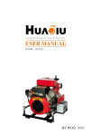
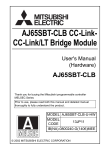
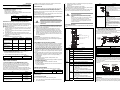
MITSUBISHI WS0-GCC100202 Safety Controller CC-Link Interface Module User’s Manual (Hardware) Mitsubishi Electric Corporation 2-7-3 Marunouchi, Chiyoda-ku, Tokyo, Japan Mitsubishi Electric Europe BV Gothaer strasse 8, 40880 Ratingen, Germany All rights reserved • Specified product properties and technical data do not represent a guarantee declaration. MODEL WS-CC-U-HW MODEL 13J209 CODE IB(NA)-0800459-D(1404)SICK © 2010 MITSUBISHI ELECTRIC CORPORATION In addition, mounting protective devices also requires specific technical skills which are not detailed in this documentation. 2 Correct use CC-Link interface module is a CC-Link based gateway and a part of the MELSEC-WS system that communicates with primary control systems. It provides non-safe fieldbus data for control and diagnostic purposes. The gateway does not have its own power supply and can only be operated with a MELSEC-WS system. *1: When the WS0-GCC100202 is included in the system, operating ambient temperature will be 0 to 55°C. *1: Avec un module WS0-GCC100202 inclus dans le système, la température ambiante de service est de 0 à 55°C. EMC standards that are applicable to the products differ. MELSEC-Q, MELSEC-WS MELSEC-QS EMC standards EN 61000-6-2, EN 55011 EN 61131-2 1 About this document 1.1 Documentations for the MELSEC-WS system These manuals apply for the MELSEC-WS CC-Link interface module WS0-GCC100202 (hereinafter, CC-Link interface module) and only in combination with the corresponding user’s manual Safety Controller CC-Link Interface Module User's Manual. The installation, configuration and commissioning of the MELSEC-WS safety control system are described in the Safety Controller User’s Manual and Safety Controller Setting and Monitoring Tool Operating Manual. Title Safety Controller User’s Manual Safety Controller Ethernet Interface User’s Manual Safety Controller CC-Link Interface User’s Manual Safety Controller Setting and Monitoring Tool Operating Manual Number WS-CPU-U-E (13JZ32) WS-ET-U-E (13JZ33) WS-CC-U-E (13JZ45) SW1DNNWS0ADRB-O-E (13JU67) output values (ON/OFF) for all MELSEC-WS input/output extension modules and EFI devices connected logic results the error and status information of all modules ! This gateway must be used only by qualified safety personnel and only on the machine where it has been installed and initialized by qualified safety personnel in accordance with the operating manuals. ATTENTION ! ATTENTION Observe the protective notes and measures in the MELSEC-WS User’s manual! Respecter les consignes de sécurité et mesures de protection décrites dans le Manuel de l'utilisateur MELSEC-WS. Mitsubishi Electric Co. accepts no claims for liability if the equipment is used in any other way or if modifications are made to the device, even in the context of mounting and installation. Name Station number setting switch Meaning A switch for configuring a station number for the module (factory default: 0) 1 to 64: Station number When the number other than 1 to 64 is configured, the MS LED flashes in red and the L RUN/L ERR. LED lights up in red. Example: Setting the station number 11 Terminal block DA, DB, DG, SLD CC-Link dedicated cables are connected for data link. For wiring, see Section 4.3. The SLD terminal is internally connected to the earthing spring contact. (the connecting part to the DIN rail). This two-piece terminal block allows a replacement of the failed module with the system being connected to CC-Link network. (Before replacement, power off the module to be replaced.) For the crimp tools, see Chapter 8. For detailed description of the data set and configuration, please read the “Safety Controller CC-Link Interface User’s Manual”. The occurrence of random or systematic faults within the module or in its control does not impede the MELSEC-WS system’s safety function. Up to two gateways can be used in a MELSEC-WS system. These must be installed directly to the right of the WS0-CPUx. Precautions regarding warranty and specifications MELSEC-WS series products are jointly developed and manufactured by Mitsubishi and SICK AG, Industrial Safety Systems, in Germany. Note that there are some precautions regarding warranty and specifications of MELSEC-WS series products. <Warranty> The gratis warranty term of the product shall be for one (1) year after the date of delivery or for eighteen (18) months after manufacturing, whichever is less. The onerous repair term after discontinuation of production shall be for four (4) years. Mitsubishi shall mainly replace the product that needs a repair. It may take some time to respond to the problem or repair the product depending on the condition and timing. <Specifications> General specifications of the products differ. MELSEC-WS MELSEC-Q MELSEC-QS Operating ambient temperature -25 to 55°C*1 0 to 55°C 0 to 55°C Température ambiante -25 à 55°C*1 0 à 55°C 0 à 55°C de fonctionnement Operating ambient 10 to 95%RH 5 to 95%RH 5 to 95%RH humidity Storage ambient -25 to 70°C -25 to 75°C -40 to 75°C temperature Storage ambient 10 to 95%RH 5 to 95%RH 5 to 95%RH humidity Do not use non-safe data from network modules for safety related applications. Network modules only processes non-safety-related data which is not suitable for operation on a safety fieldbus. Ne pas utiliser les données non-sécurisés des modules réseau pour des applications liées à la sécurité. Les modules réseau ne véhiculent que des données non-sécurisées impropres à l'exploitation en bus de sécurité sur le terrain. 4.2 Display elements The CC-Link interface module is equipped with two LEDs: MS and L RUN/ L ERR. 4.3 CC-Link dedicated cable connection Connexion par câble dédié CC-Link When mounting, installing and using the MELSEC-WS system, observe the standards and directives applicable in your country. These manuals and the related operating manuals must be made available to the user of the machine where a MELSECWS system is installed. The machine operator is to be instructed in the use of the device by qualified safety personnel and must be instructed to read the operating manuals. The following shows the connection between the CC-Link interface module and the master station using a CC-Link dedicated cable. La connexion entre le module d'interface CC-Link et la station maître par câble dédié CC-Link est illustrée ci-après. MS LED 2.1 Disposal Disposal of unusable or irreparable devices should always occur in accordance with the applicable country-specific wastedisposal regulations (e.g. European Waste Code 16 02 14). Station number setting switch 10 Station number setting switch 1 L RUN/L ERR. LED 3 Conditions of use for the product (1) Although MELCO has obtained the certification for Product's compliance to the international safety standards IEC 61508, EN 954-1/ISO 13849-1 from TUV Rheinland, this fact does not guarantee that Product will be free from any malfunction or failure. The user of this Product shall comply with any and all applicable safety standard, regulation or law and take appropriate safety measures for the system in which the Product is installed or used and shall take the second or third safety measures other than the Product. MELCO is not liable for damages that could have been prevented by compliance with any applicable safety standard, regulation or law. (2) MELCO prohibits the use of Products with or in any application involving, and MELCO shall not be liable for a default, a liability for defect warranty, a quality assurance, negligence or other tort and a product liability in these applications. 1) power plants, 2) trains, railway systems, airplanes, airline operations, other transportation systems, 3) hospitals, medical care, dialysis and life support facilities or equipment, 4) amusement equipments, 5) incineration and fuel devices, 6) handling of nuclear or hazardous materials or chemicals, 7) mining and drilling, 8) and other applications where the level of risk to human life, health or property are elevated. Terminal block SLD DG MS L RUN/ L ERR. LED Off Lights up Green Flashes Green Flashes Green/Red Flashes Red Lights up Red OFF Lights up Green Flashes Green/Red 4 Product description Before using the module, check that the following items are provided. Item Amount Remarks WS0-GCC100202 1 Terminating resistor 110Ω 1/2W 1 Bar terminal (brown-brown-brown) Screw terminals (for replacement) (WS0-TBS4) are not available for the WS0-GCC100202. Flashes Red 4.1 Communication data The CC-Link interface module provides the following data: input values (ON/OFF) for all MELSEC-WS extension modules and EFI devices connected Lights up Red DA DB Meaning No power supply, immediately after the module start or hardware failure Executing (live process data from/to CPU) Idle (CPU STOP) Executing, but data link stopped or faulty 1 Hz: Configuring/configuration required 2 Hz: Critical fault on CC-Link interface module Critical fault on another module No power supply or data link stopped Data link active One of the following has been detected when data link is active. Configuration change of the station number setting switch Terminating register not connected Module or CC-Link dedicated cable affected by noise One of the following has been detected when data link is stopped. Configuration change of the station number setting switch Terminating register not connected Module or CC-Link dedicated cable affected by noise Station number setting switch out-of-range English Master station CC-Link interface module Terminating resistor CC-Link dedicated cable Blue White Yellow French Station maître Module d'interface CC-Link Résistance d'extrémité Câble dédié pour CC-Link bleu blanc jaune Use a bar terminal to connect the cable to the CC-Link interface module. For applicable bar terminals, see Chapter 8 Cable specifications. Two poles of each terminal are internally connected. (See below.) Utiliser une borne-barre pour raccorder le câble au module d'interface CC-Link. Pour les bornes-barres qui peuvent s'utiliser, voir Spécifications des câbles au chapitre 8. Pour chaque borne, il y a deux pôles connectés à l'intérieur. (Voir ci-dessous.) English Terminating resistor French Résistance d'extrémité The above figure shows a view from under the module after wiring. La figure ci-dessus représente le module vue par en bas après câblage. 4.4 Interface The CC-Link interface module has a removable terminal block for network connection. The module can be easily replaced without re-wiring. (The voltage supply to the module must be off before replacing the module.) 5 Mounting/Dismantling ! ATTENTION The MELSEC-WS system is only suitable for mounting in a control cabinet with at least IP54 degree of protection. While supply voltage is applied, gateways must not be plugged to nor be removed from the MELSEC-WS system. To ensure full electromagnetic compatibility (EMC), the DIN mounting rail must be connected to functional earth (FE). Le système MELSEC-WS ne peut être installé que dans une armoire de commande avec un degré de protection IP 54 ou mieux. Les passerelles ne doivent pas être enfichées ou retirées du système MELSEC-WS quand la tension d'alimentation est appliquée. Pour garantir totalement la compatibilité électromagnétique (EMC), le rail de fixation DIN doit être raccordé à la terre fonctionnelle (FE). 5.1 Steps for mounting the modules In a MELSEC-WS system the CPU module WS0-CPU0 or WS0-CPU1 is positioned at the extreme left, the two optional gateways follow directly. Only then do the expansion modules follow. The relays modules WS0-4RO have to be mounted at the extreme right. The modules are located in a 22.5-mm wide modular system for 35 mm DIN rails to EN 60715. The connection between the modules is effected by means of the plug connection integrated in the housing. Mount the module in accordance with EN 50274. Ensure that suitable ESD protective measures are also taken during mounting. Otherwise the FLEXBUS+ bus may be damaged. 2) 1) General specifications 2) Press the module downwards at the rear 1) and remove it from the DIN rail in the direction of the arrow while keeping it pressed down 2). 6 Configuration and commissioning ! ATTENTION 7 In the event of faults ATTENTION 3) Do not commission without a check by specialist personnel! Ne pas procéder à la mise en service sans qu'un personnel spécialisé ait effectué un contrôle ! Before the initial commissioning of the system in which you are using a MELSEC-WS system, it must be checked and released by qualified safety personnel. The results of this check must be documented. La première mise en service d'un système utilisant un système MELSEC-WS ne doit être effectuée qu'après contrôle et sur autorisation délivrée par un personnel de sécurité qualifié. Les résultats de ce contrôle doivent être dûment documentés et suivis. The CC-Link interface module can be configured using the MELSEC-WS Setting and monitor tool via the WS0-CPUx module’s RS232 interface. ! 1) Item Specifications CC-Link interface 1 terminal block at the lower part of the module Cable Ver.1.10-compatible CC-Link dedicated cable*1 Data interface Backplane bus (FLEXBUS+) *1: Connect a terminating resistor (110Ω). Make sure that the voltage supply of the MELSEC-WS system is switched off. Hang the device onto the DIN rail 1). Ensure that the earthing spring contact 2) contacts the DIN rail such that it can electrically conduct. Latch the module onto the DIN rail by pressing it lightly in the direction of the arrow 3). In the event of unclear faults, cease operation! En présence d'anomalie d'origine indéterminée, interrompez la marche ! Stop the machine if you cannot clearly identify or allocate the error and if you cannot safely rectify the malfunction. Arrêter la machine si on ne parvient pas à identifier l'erreur, à en déterminer l'origine et à corriger l'anomalie de manière fiable. Complete functional test after error rectification! Menez à bien les essais de fonctionnement après correction des erreurs ! Carry out a full functional test after an error has been rectified. Toujours effectuer des essais de fonctionnement complets après avoir corrigé une erreur. 8 Technical data Supply circuits Item Supply voltage Specifications 24 V DC (16.8 … 30 V DC) Power consumption Max. 1.4 W Interfaces Slide the modules together individually in the direction of the arrow until the side plug connection latches in. Install the end clips on the right and left. 5.2 Steps for dismantling the modules Remove the plug-in package terminals with wiring and the end clips. If there are several modules, slide the modules away from each other individually in the direction of the arrow until the side plug connection is separated. Item Fieldbus CC-Link station type CC-Link Version Data transmission speed Station number Number of occupied stations Specifications CC-Link Remote device station Ver.1.10 156kbps/625kbps/2.5Mbps/5Mbps/10Mbps (autosensing) 1 to 64 (factory default: 0) 1 station (RX/RY 32 points each, RWw/RWr 4 points each)/ 2 stations (RX/RY 64 points each, RWw/RWr 8 points each)/ 3 stations (RX/RY 96 points each, RWw/RWr 12 points each)/ 4 stations (RX/RY 128 points each, RWw/RWr 16 points each) (The last 16 points of RX/RY are for system use (reserved).) Item Fieldbus FLEXBUS+ Ambient operating temperature Température ambiante de fonctionnement Storage temperature Humidity Climatic conditions Vibration Rigidity Protection class Electromagnetic compatibility Housing material Housing type Housing enclosure rating/terminals Housing color Weight Mounting rail Specifications CC-Link 10-pin connector for internal safety bus (plug) 0°C to +55°C 0 à +55°C -25°C to +70°C 10% to 95%, non-condensing According to EN 61131-2 Tested in accordance with IEC 61131-2. Tested in accordance with IEC 61131-2. lll IEC 61000-6-2, EN 55011 Class A Polycarbonate Device for control cabinet installation IP40/IP20 according to IEC 60529 Cable size Taille de câble Temperature rating Gamme de température Material Matériau Core type Type d'âme Solderless terminal (bar terminal) and crimp tool Solderless terminal (bar terminal) and crimp tool Tightening torque range Plage de couple de serrage Light grey 120 g Mounting rail according to IEC/EN 60715 Specifications Caractéristiques For the specifications and any inquiries on the CC-Link dedicated cables, refer to the following: CC-Link Partner Association website: http://www.cc-link.org/ Pour les caractéristiques des câbles dédiés CC-Link ou toute demande de renseignements, consulter le site internet de CC-Link Partner Association :http://www.cc-link.org/ 20AWG -15°C to +75°C -15 à +75°C Brazil Germany UK Italy Spain France Czech Republic Poland Russia South Africa China Taiwan Conductor: Annealed copper wire (finely stranded) Conducteur: Fil de cuivre recuit (torsade fine) Finely stranded Torsade fine 1) Mitsubishi Electric Engineering Co.,Ltd. Bar terminal model: FA-TVC125T9 Crimp tool : FA-NH65A 2) NICHIFU Co.,Ltd. Bar terminal model: TE0.5-10 (for CC-Link dedicated cable (0.5mm2)), TE1.5-10 (for SLD) Crimp tool: NH-79 3) PHOENIX CONTACT Bar terminal model: AI0.5-10WH (for CC-Link dedicated cable (0.5mm2)), AI1.5-10BK (for SLD) Crimp tool: CRIMPFOX UD6, CRIMPFOX UD6-4, CRIMPFOX UD6-6, and CRIMPFOX ZA3 *Note: When a shielded cable is excessively crimped to a bar terminal using a tool, CRIMPFOX UD6-4 or CRIMPFOX UD6-6, the bar terminal may not be connected to the terminal block depending on the cross-sectional shape after crimping. Specifications Caractéristiques 1) Mitsubishi Electric Engineering Co.,Ltd. Modèle de borne-barre : FA-TVC125T9 Outil de sertissage : FA-NH65A 2) NICHIFU Co.,Ltd. Modèle de borne-barre: TE0,5-10 (pour câble dédié CC-Link (0,5mm2)), TE1,5-10 (pour SLD) Outil de sertissage: NH-79 3) PHOENIX CONTACT Modèle de borne-barre: AI0,5-10WH (pour câble dédié CC-Link (0,5mm2)), AI1,5-10BK (pour SLD) Outil de sertissage: CRIMPFOX UD6, CRIMPFOX UD6-4, CRIMPFOX UD6-6, and CRIMPFOX ZA3 *Note: Si un câble blindé est serti trop fortement sur une borne-barre avec un outil comme CRIMPFOX UD6-4 ou CRIMPFOX UD6-6, il arrive que la section résiduelle de la borne-barre après sertissage ne permettent pas un bon contact sur la plaque à bornes. No torque range specified since two-tier tension-spring terminal is used. S'agissant d'une borne avec ressort à tension sur deux niveaux, le couple de serrage n'est pas indiqué. Country/Region Sales office/Tel USA Cable specifications Spécifications des câbles Item Rubrique Ver1.10-compatible CC-Link dedicated cable Câble dédié CC-Link compatible Ver1.10 Item Rubrique Solderless terminal (bar terminal) and crimp tool Solderless terminal (bar terminal) and crimp tool Korea Singapore Thailand Indonesia India Australia Mitsubishi Electric Automation lnc. 500 Corporate Woods Parkway, Vernon Hills, IL 60061, USA Tel : +1-847-478-2100 MELCO-TEC Representacao Comercial e Assessoria Tecnica Ltda. Av. Paulista, 1439, cj74, Bela Vista, Sao Paulo CEP: 01311-200-SP Brazil Tel : +55-11-3146-2200 Mitsubishi Electric Europe B.V. German Branch Gothaer Strasse 8, D-40880 Ratingen, Germany Tel : +49-2102-486-0 Mitsubishi Electric Europe B.V. UK Branch Travellers Lane, Hatfield, Hertfordshire, AL10 8XB, UK. Tel : +44-1707-27-6100 Mitsubishi Electric Europe B.V. Italian Branch Viale Colleoni 7-20864 Agrate Brianza (Milano), Italy Tel : +39-039-60531 Mitsubishi Electric Europe B.V. Spanish Branch Carretera de Rubi 76-80.AC.420, E-08190 Sant Cugat del Valles (Barcelona), Spain Tel : +34-93-565-3131 Mitsubishi Electric Europe B.V. French Branch 25, Boulevard des Bouvets, F-92741 Nanterre Cedex, France Tel : +33-1-5568-5568 Mitsubishi Electric Europe B.V.-o.s.Czech office Avenir Business Park, Radicka 751/113e, 158 00 Praha5, Czech Republic Tel : +420-251-551-470 Mitsubishi Electric Europe B.V. Polish Branch ul. Krakowska 50, 32-083 Balice, Poland Tel : +48-12-630-47-00 Mitsubishi Electric Europe B.V. Russian Branch St.Petersburg office Piskarevsky pr. 2, bld 2, lit "Sch", BC "Benua", office 720; 195027, St. Petersburg, Russia Tel : +7-812-633-3497 CBI-Electric. Private Bag 2016, ZA-1600 Isando, South Africa Tel : +27-11-977-0770 Mitsubishi Electric Automation (China) Ltd. No.1386 Hongqiao Road, Mitsubishi Electric Automation Center, Changning District, Shanghai, China Tel : +86-21-2322-3030 Setsuyo Enterprise Co., Ltd. 6F., No.105, Wugong 3rd Road, Wugu District, New Taipei City 24889, Taiwan, R.O.C. Tel : +886-2-2299-2499 Mitsubishi Electric Automation Korea Co., Ltd. 3F, 1480-6, Gayang-Dong, Gangseo-Gu, Seoul, 157-200, Korea Tel : +82-2-3660-9530 Mitsubishi Electric Asia Pte, Ltd. Industrial Division 307, Alexandra Road, Mitsubishi Electric Building, Singapore, 159943 Tel : +65-6470-2308 Mitsubishi Electric Automation (Thailand) Co., Ltd. Bang-Chan Industrial Estate No.111 Soi Serithai 54, T.Kannayao, A.Kannayao, Bangkok 10230 Thailand Tel : +66-2906-3238 P. T. Autoteknindo Sumber Makmur Muara Karang Selatan, Block A / Utara No.1 Kav. No. 11, Kawasan Industri Pergudangan, Jakarta-Utara 14440, P.O, Box 5045, Indonesia Tel : +62-21-663-0833 Mitsubishi Electric India Pvt. Ltd. 2nd Floor, Tower A & B, Cyber Greens, DLF Cyber City, DLF Phase-III, Gurgaon-122002 Haryana, India Tel : +91-124-463-0300 Mitsubishi Electric Australia Pty. Ltd. 348 Victoria Road PO BOX11, Rydalmere, N.S.W 2116, Australia Tel : +61-2-9684-7777 HEAD OFFICE : TOKYO BUILDING, 2-7-3 MARUNOUCHI, CHIYODA-KU, TOKYO 100-8310, JAPAN NAGOYA WORKS : 1-14, YADA-MINAMI 5-CHOME, HIGASHI-KU, NAGOYA, JAPAN When exported from Japan, this manual does not require application to the Ministry of Economy, Trade and Industry for service transaction permission. Specifications subject to change without notice. SICK AG http://www.sick.com/