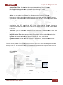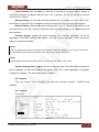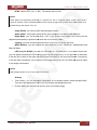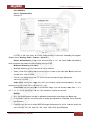
1
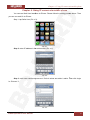
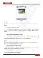
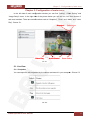
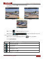
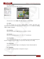
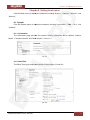
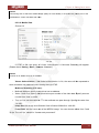
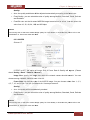
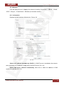
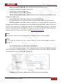
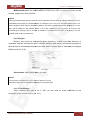
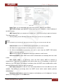
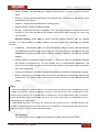
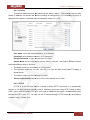
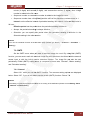
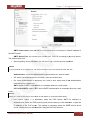
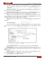
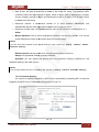
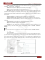
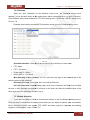
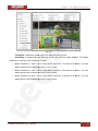
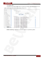
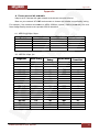
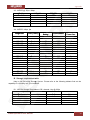
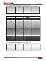
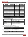
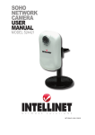
Operations User Manual
16 channel Surveillance software included
Built-in multi-zone motion and audio detection
Table of contents
Table of contents
CHAPTER 1. SAFETY INSTRUCTIONS ............................................................................................................ 3
1.1. BEFORE YOU USE THIS PRODUCT ............................................................................................................... 3
CHAPTER 2. SYSTEM REQUIREMENTS AND PRODUCT FEATURES.......................................................... 5
2.1. SYSTEM REQUIREMENTS ........................................................................................................................... 5
2.2. PRODUCT FEATURES ................................................................................................................................. 6
CHAPTER 3. USING IP CAMERA VIA WEB BROWSER.................................................................................. 7
3.1. W INDOWS WEB BROWSER ......................................................................................................................... 7
3.2. MAC WEB BROWSER................................................................................................................................. 7
CHAPTER 4. USING IP CAMERA VIA MOBILE PHONE ................................................................................ 10
4.1. USING IP CAMERA VIA PHONE....................................................................................................................11
4.2.1. 3G Mobile Phone Streaming Viewing ........................................................................................................... 11
4.2.2. 2.5G Mobile Phone WAP Viewing ................................................................................................................. 11
4.2.3. 2.5G Mobile Phone Browser Viewing............................................................................................................ 11
CHAPTER 5. CONFIGURATION OF MAIN MENU .......................................................................................... 12
5.1. LIVE VIEW............................................................................................................................................... 12
5.1.1. Snapshot ....................................................................................................................................................... 12
5.1.2. Zoom in / out the image via the monitor window ........................................................................................ 13
5.1.3. Video Play Buttons ........................................................................................................................................ 13
5.1.4. Audio Buttons................................................................................................................................................ 14
5.2. SETTING ................................................................................................................................................. 14
5.3. CLIENT SETTING ...................................................................................................................................... 15
5.3.1. Mode............................................................................................................................................................. 15
5.3.2. View Size ....................................................................................................................................................... 15
5.3.3. Protocol......................................................................................................................................................... 15
5.3.4. Video Buffer .................................................................................................................................................. 15
5.4. IMAGE SETUP .......................................................................................................................................... 15
5.4.1. Brightness ..................................................................................................................................................... 15
5.4.2. Contrast......................................................................................................................................................... 16
5.4.3. Saturation ..................................................................................................................................................... 16
5.4.4. Hue................................................................................................................................................................ 16
5.4.5. Default .......................................................................................................................................................... 16
CHAPTER 6. SETTING-BASIC MENU............................................................................................................. 17
6.1. SYSTEM ................................................................................................................................................. 17
6.1.1. Information ................................................................................................................................................... 17
6.1.2. Date/Time ..................................................................................................................................................... 17
6.1.3. Initialize......................................................................................................................................................... 18
6.2. CAMERA ................................................................................................................................................. 19
6.2.1. General.......................................................................................................................................................... 19
6.2.2. MPEG-4 ......................................................................................................................................................... 21
6.2.2.1. Computer View........................................................................................................................................... 21
6.2.2.2. Mobile View ............................................................................................................................................... 22
6.2.3. MJPEG ........................................................................................................................................................... 23
6.3. NETWORK............................................................................................................................................... 24
6.3.1. Information ................................................................................................................................................... 24
6.3.2. PPPoE (Point-to-Point Protocol over Ethernet).............................................................................................. 25
6.3.3. DDNS (Dynamic DNS) .................................................................................................................................... 26
6.3.4. UPnP (Universal Plug and Play)..................................................................................................................... 30
6.3.5. Bonjour.......................................................................................................................................................... 31
6.3.6. IP notification................................................................................................................................................ 31
6.3.7. Wireless (only for N1250).............................................................................................................................. 33
6.4. SECURITY ............................................................................................................................................... 34
6.4.1. Account ......................................................................................................................................................... 35
6.4.2. HTTPS ............................................................................................................................................................ 35
CHAPTER 7. SETTING-ADVANCED MENU.................................................................................................... 37
7.1. FTP CLIENT ............................................................................................................................................ 37
N1000 Operations User Manual
1
Table of contents
7.1.1. General.......................................................................................................................................................... 37
7.1.2. Alarm Sending............................................................................................................................................... 38
7.1.3. Periodical Sending......................................................................................................................................... 39
7.2. SMTP.................................................................................................................................................... 40
7.2.1. General.......................................................................................................................................................... 40
7.2.2. Alarm Sending............................................................................................................................................... 42
7.2.3. Periodical Sending......................................................................................................................................... 43
7.3. HTTP EVENT .......................................................................................................................................... 44
7.4. SCHEDULE .............................................................................................................................................. 45
7.5. MOTION DETECTION ................................................................................................................................ 45
7.6. SYSTEM LOG........................................................................................................................................... 47
APPENDIX......................................................................................................................................................... 48
A. FRAME RATE AND BIT RATE TABLE ............................................................................................................ 48
B. STORAGE REQUIREMENT TABLE............................................................................................................... 49
C. TESTING SYSTEM SPECIFICATION............................................................................................................. 51
D. D1 PERFORMANCE OF 16 CHANNEL IP CAMERA........................................................................................ 51
EUROPE – EU DECLARATION OF CONFORMITY .................................................................................................. 52
FEDERAL COMMUNICATION COMMISSION INTERFERENCE STATEMENT ................................................................ 53
N1000 Operations User Manual
2
Chapter 1. Safety instructions
Chapter 1. Safety instructions
1.1. Before you use this product
This product has been designed with safety in mind. However, the electrical products can
cause fires which may lead to serious body injury if not used properly. To avoid
such accidents, be sure to heed the following:
Legal Caution
Video and audio surveillance can be forbidden by laws that vary from country to country.
Check the laws in your local region before using this product for surveillance purposes;
Do not open the housing of the product
Do not try to open the housing or remove the covers which may expose yourself to
dangerous voltage or other hazards;
Do not use the accessories not recommend by the manufacturer
Heed the safety precautions
Be sure to follow the general safety precautions and the “Operation Notice”;
Operation Notice - Operating or storage location
Avoid operating or storing the camera in the following locations:
•
Extremely hot or cold places;
•
(Operating temperature: 0 °C to + 50 °C [32 °F to 122°F]);
•
Exposed to direct sunlight for a long time, or close to heating equipment (e.g., near
heaters);
•
Close to water (e.g., near a bathtub, kitchen sink, laundry tub);
•
Close to sources of strong magnetism;
•
Close to sources of powerful electromagnetic radiation, such as radios or TV
transmitters;
•
Locations subject to strong vibration or shock.
In case of a breakdown
In case of system breakdown, discontinue use and contact your authorized dealer.
In case of abnormal operation:
•
If the unit emits smoke or an unusual smell;
•
If water or other foreign objects enter the cabinet;
•
If you drop the unit or damage the cabinet: 1 Disconnect the cable and the connecting
cables. 2 Contact your authorized dealer or the store where you purchased the
product.
N1000 Operations User Manual
3
Chapter 1. Safety instructions
Transportation
When transporting the camera, repack it as originally packed at the factory or in materials of
equal quality.
Ventilation
To prevent heat buildup, do not block air circulation around the device.
Cleaning
•
Use a soft, dry cloth to clean the external surfaces of the device. Stubborn stains can
be removed using a soft cloth dampened with a small quantity of detergent solution,
then wipe dry.
•
Do not use volatile solvents such as alcohol, benzene or thinners as they may damage
the surface.
N1000 Operations User Manual
4
Chapter 2. System requirements and product features
Chapter 2. System requirements and product features
2.1. System requirements
We strongly recommend that the computer you have meets the following minimum
requirements in order to use this IP Camera normally. If computer level is lower than this, it might
cause problems of the IP camera usage.
CPU: Pentium 4 1600MHz (or equivalent AMD)
Graphic Card: 64 MB RAM graphic cards (or equivalent on-board graphic cards)
RAM: 512 MB
Operating System: Windows 98, Windows ME (Please see the Note below), Windows
2000, 2003, XP, Vista, Mac OS X Leopard
Web Browser: Internet Explorer 6 or later
NOTE!
1. If you use Windows 98 or Windows ME, please install IP Installer before using WEB UI to ensure the
system runs normally.
2. If you cannot view the record video file, please install Xvid codec while installing Intelligent IP Installer.
(For Windows 98, ME or 2000 server, the codec might not work properly. You will need to download Xvid
codec 1.0 from the Internet.
3. Please always update the latest Windows components. (.Net Framework, Windows Media Player,
Enhance ActiveX Security).
N1000 Operations User Manual
5
Chapter 2. System requirements and product features
2.2. Product features
SYSTEM
Resolutions
Compressing format
Frame Rate
MPEG-4 / Motion JPEG / JPEG:
2 resolutions from 640x480 to 320x240 via API and
configuration web page
MPEG-4 / Motion JPEG / JPEG
MPEG-4: Up to 30 fps at 640x480
Motion JPEG: Up to 15 fps at 640x480
Rotation: Mirror, Flip, Mirror Flip
Image settings
Brightness / Contrast / Saturation / Hue
Overlay capabilities: time, date, text and privacy image
Shutter Time
Image snapshot
Video Recording
Full Screen Viewing
Digital Zoom
Audio
Mobile Phone Live View
Alarm Sending
Security
Alarm and Event Management
Supported protocols
Simultaneous Connection
Operating conditions
1/7.5 ~ 1/120 sec.
Yes
Yes
Yes
10x digital
Two-way (full / half duplex) with built-in microphone
Audio compression: G.711 PCM, 8kHz, 64kbit/s
Through 2.5 WAP, 3GPP, 3G Streaming, and 3G Browser
FTP Client / SMTP
Password Protection / HTTPS encryption / WEP64/128 bit,
WPA/WPA2-PSK
Input: motion diction
Output: FTP/SMTP/HTTP Event
Bonjour, TCP/IP, DHCP, PPPoE, ARP, ICMP, FTP,
SMTP, DNS, NTP, UPnP, RTSP, RTP, HTTP, TCP, UDP,
3GPP/ISMA RTSP
Up to 5 users
0°C ~ 50 ℃ (32℉ ~ 122 ℉)
HARDWARE
Lens
LEDs / Working Distance
Power
Wireless
N1000 Operations User Manual
F2.0, 4.0mm board lens
5 φ LEDs x 6 / 5M (for N1250)
5V DC, 1A, Max 5W
IEEE 802.11b/g (for N1250)
6
Chapter 3. Using IP camera via web browser
Chapter 3. Using IP camera via web browser
3.1. Windows web browser
Step 1: start your web browser, and enter the IP address or host name of the IP camera in
the Location / Address field of your browser.
NOTE!
If you only want to view the video without making any settings, enter “http://<IP>/index2.htm” in address
bar of your browser.
Step 2: enter the default user name “admin” and default password “admin”.
NOTE!
The default user name “admin” and the password are set at the factory for the administrator. You can
change them in the Account Menu (Please check “Setting → Basic → Security → Account”). Picture
3.1.
Pic. 3.1
Step 3: the monitor image will be displayed in your browser. In the left side of main
configuration window you can see Setting, Client Setting, and Image Setup menu. For more details
see Chapter 5.2., Chapter 5.3. and Chapter 5.4.
3.2. MAC web browser
Step 1: click the Safari icon, and enter the IP address of the IP camera in the Location /
Address field of your browser.
NOTE!
If you only want to view the video without making any settings, enter “http://<IP>/index2.htm in the address
bar of your browser. Picture 3.2.
N1000 Operations User Manual
7
Chapter 3. Using IP camera via web browser
Pic. 3.2
Step 3: use the default user name “admin” and default password “admin”.
NOTE!
The default user name “admin” and the password are set at the factory for the administrator. You can
change them in the Account Menu (Please check “Setting → Basic → Security → Account”)
Picture 3.3.
Pic. 3.4
Step 4: image from the camera will be displayed in your browser. In the left side of main
configuration you can find Setting, Client Setting, and Image Setup menu. For more details, you
see Chapter 5.2, Chapter 5.3 and Chapter 5.4. Picture 3.4.
N1000 Operations User Manual
8
Chapter 3. Using IP camera via web browser
Pic. 3.4
N1000 Operations User Manual
9
Chapter 4. Using IP camera via mobile phone
Chapter 4. Using IP camera via mobile phone
You can use Web User Interface via iPhone. Please follow the setting process below. Then
you can use web UI via iPhone.
Step 1: tap Safari icon (Pic. 4.1).
Pic. 4.1
Step 2: enter IP address in the address bar (Pic. 4.2).
Pic. 4.2
Step 3: enter user name and password. Default values are admin / admin. Then click Login
In. Picture 4.3.
Pic. 4.3
N1000 Operations User Manual
10
Chapter 4. Using IP camera via mobile phone
Step 4: the User Interface and live image will be displayed in the middle of screen. Picture 4.4.
Pic. 4.4
NOTE!
It will show continuous snapshots not a real time video streaming. Therefore, the recording feature is
disabled.
4.1. Using IP camera via phone
To use IP cameras via mobile phones, please make sure your RTSP is set to “On” (Default
is “On”). To change the settings of IP cameras, please check Settings - Basic - Camera General.
4.2.1. 3G Mobile Phone Streaming Viewing
For 3G mobile phone viewing, type “rtsp://<IP>:<PORT>/video.3gp” into your 3G
Streaming Link. “IP” is the Public IP address of your IP camera; “PORT” is the RTSP port of your
IP camera (Default value is 554.) Example: rtsp://100.10.10.1:554/video.3gp.
NOTE!
You can also use RTSP clients (RealPlayer, VLC, QuickTime layer…etc.) to view RTSP streaming, just
type in “rtsp://<IP>:<PORT>/video.3gp” as the Player URL.
4.2.2. 2.5G Mobile Phone WAP Viewing
For 2.5G mobile phone viewing, type “http://<IP>/mobile.wml ” into your 2.5G WAP
Browser. “IP” is the Public IP address of your IP camera.
4.2.3. 2.5G Mobile Phone Browser Viewing
For 2.5G mobile phone viewing, type “http://<IP>/mobile.htm ” into your 2.5G Web Browser.
“IP” is the Public IP address of your IP camera.
N1000 Operations User Manual
11
Chapter 5. Configuration of main menu
Chapter 5. Configuration of main menu
In the left side of main configuration window you can find “Setting”, “Client Setting” and
“Image Setup” menu. In the right side of the picture below you can see the Live View screen of
web user interface. There are some functions such as “Snapshot”, “Zoom” and “Audio” and “Video
Play”. Picture 5.1.
Snapshot
Video Play
Audio Button
Full screen
Zoom In/Out
Pic. 5.1
5.1. Live View
5.1.1. Snapshot
You can capture a still image shot by the camera and save it in your computer. Picture 5.2.
Pic. 5.2
N1000 Operations User Manual
12
Chapter 5. Configuration of main menu
5.1.2. Zoom in / out the image via the monitor window
Picture 5.3, 5.4.
Pic. 5.3
Pic 5.4
Pic 5.5
Step 1: click
to display the digital zoom in window.
Step 2: pull to
adjust the digital zoom range and
it will be showed on the above window.
Step 3: you can use left mouse button to move the
anywhere on the window.
5.1.3. Video Play Buttons
Symbols
Meaning
Pause the current video
Play the video
Stop the current video
Record the current video
N1000 Operations User Manual
13
Chapter 5. Configuration of main menu
NOTE!
Concerning the recording storage requirement of your hard disk, please refer to the APPENDIX B.
Storage Requirement Table.
5.1.4. Audio Buttons
Symbols
Meaning
Note
means the speakers of your computer are
turned on to transmit sound from the
connected IP camera(s)
Speakers turned on
Speakers turned off
means you can broadcast to the connected
IP camera(s) via the Ethernet using your
microphone
Microphone turned on
Microphone turned off
Volume control bar
5.2. Setting
This function is only for the Administrator. Click this button to get into the Basic and
Advanced Setting menu. The former includes for sub-folders, such as System, Camera, Network,
and Security. The latter includes FTP Client, SMTP, Http Event, Schedule, Motion Detection, and
System Log. Picture 5.6.
Pic. 5.6
N1000 Operations User Manual
14
Chapter 5. Configuration of main menu
5.3. Client setting
This function is only for the client. Picture 5.7.
Pic. 5.7
Click this button to control Mode, View Size, Protocol, and Video Buffer.
5.3.1. Mode
Click the pull-down box to choose between MPEG-4, MJPEG, and JPEG video
compression mode. MJPEG streaming is unavailable if RTSP mode is “On.” (Please check Setting
- Basic - Camera – General).
5.3.2. View Size
Select the desired display image resolution to 640X480 or 320X240.
5.3.3. Protocol
Select the transferring protocol from TCP, UDP, HTTP and Multicast.
5.3.4. Video Buffer
Turn the Video Buffer function On/Off. The Video Buffer function makes the streaming more
smooth in unsteady network environment, but might cause a little delay in live viewing.
5.4. Image setup
You can use the tool bar to optimize video Brightness, Contrast, Saturation and Hue.
5.4.1. Brightness
The higher value the brightness is, the brighter the image is.
N1000 Operations User Manual
15
Chapter 5. Configuration of main menu
5.4.2. Contrast
The contrast is a measure of a display system, defined as the ratio of white to black that the
system is capable of producing. The higher value the contrast is, the more delicate of color you can
have.
5.4.3. Saturation
The saturation of a color is determined by a combination of light intensity and how much it
is distributed across the spectrum of different wavelengths. The higher value the saturation is, the
more colorful the image will be.
5.4.4. Hue
Hue is one of the three main attributes of perceived color, affected by different wavelength
of color. With higher value of hue, color will be much more vivid.
5.4.5. Default
After the adjustment of all setting, you can still click Default to make the setting back to the
original setting.
N1000 Operations User Manual
16
Chapter 6. Setting-basic menu
Chapter 6. Setting-basic menu
Click the Basic menu to display the submenu including “System”, “Camera”, “Network”, and
“Security”.
6.1. System
Click the System menu to display the submenu including “Information”, “Date / Time”, and
“Initialize”.
6.1.1. Information
The Information page provides the product factory information which includes “Product
Name”, “Firmware Version” and “Web Version”. Picture 6.1.
Pic. 6.1
6.1.2. Date/Time
The Date/ Time page displays all options of time setting. Picture 6.2.
Pic. 6.2
N1000 Operations User Manual
17
Chapter 6. Setting-basic menu
Current Date / Time: this displays the current date and time of this IP Camera.
PC Clock: this displays the date and time of the monitoring PC clock.
Date / Time Format: you can click the pull down box to select different time display
formats.
Adjust: you can select one of those four adjusting modes for your IP Camera.
•
Keep current setting: select this mode to keep the current date and time of this IP Camera.
•
Synchronize: select this mode to keep the date and time of this IP Camera the same as the
monitoring PC.
•
Manual setting: select this mode to adjust manually the date and time of this IP Camera.
•
Synchronize with NTP: specify the NTP server name and the Refresh Interval to
synchronize the date and time of this IP Camera with those of the time server, known as the
NTP server.
Time Zone: you can select the Time Zone of the format from Greenwich Mean Time. The
time will display the same as the current date / time option.
Daylight Saving Time: there are two modes to choose for setting up daylight saving time.
By Date: set the start and end time by select month, day, hour, and minute.
By Week Number: set the start and end time by select month, week, hour, and minute.
NOTE!
The NTP server (Network Time Protocol) is the time server which is an Internet standard protocol built on
the top of TCP / IP. This assures accurate synchronization to the millisecond of computer clock times in a
network of computers.
6.1.3. Initialize
Picture 6.3.
Pic. 6.3
Reboot: click this button to reboot. A confirmation dialogue will appear and then click “OK”
to process. It takes two minutes to reboot this IP Camera.
N1000 Operations User Manual
18
Chapter 6. Setting-basic menu
Factory Default: click this button to reset this IP Camera to the factory default setting. A
confirmation dialogue will appear and then click “OK” to process. Do not turn off this IP Camera
until the device reboots.
Backup Setting: you can save the setting data of this IP Camera into a file. Click “Save”
and follow the instructions on the browser to save the setting data file to your specified location.
Restore Setting: download the saved setting data of this IP Camera. Click “Browse” and
select saved file. Click “OK” and this IP Camera will be adjusted according to the loaded data and
then restarted.
Firmware Update: upgrade the device software. Click “Browse” and select the file for
upgrading. A confirmation dialogue will appear. Click “OK” to start upgrading. The IP camera will
reboot to complete the update.
NOTE!
Use only upgrade files that are special for this IP Camera. Otherwise problems may occur. Do not turn off
the IP Camera power or disconnect the network until the upgrading is completed.
NOTE!
After upgrading new firmware, please execute “Factory Default” first to make it work.
Upload Language Pack: upgrade the device language pack. Click “Browse” and select the
file for upgrading. A confirmation dialogue will appear. Click “OK” to start upgrading. The upgrade
is applied immediately. The default language is “English.”
6.2. Camera
Click the Camera menu to display the submenu including “General”, “MPEG4” and
“MJPEG.”
6.2.1. General
Picture 6.4
Pic. 6.4
N1000 Operations User Manual
19
Chapter 6. Setting-basic menu
RTSP: switch RTSP “On” or “Off.” The default value is 554.
NOTE!
RTSP (Real Time Streaming Protocol) is a protocol for use in streaming media system which allows
clients to remotely control a streaming video server. RTSP is supported by most of the media clients such
as Real Player, QuickTime, VLC, etc.
Image Rotate: you can mirror or flip the display screen.
Audio Codec: if this option is turned On, the microphone will start sound reception.
Night Mode: you can choose Auto / Off. If you choose Auto option, the camera will be
adjusted automatically to perform well when the environment is dark.
Lighting: you can choose the environment among 50 Hz, 60 Hz, and Auto.
White Balance: you can choose the white balance to Auto, Florescent, Incandescent and
Black & White.
LED (only for N1250): you can turn LED light On / Off and Auto. If you select Auto mode,
you can adjust threshold for LED Auto-On and Auto-Off respectively. In the right side of threshold,
if the tool bar is closer to the right, the LED will auto-on easily in the dark environment. Conversely,
in the left side of threshold, if the tool bar is more approach to the left, the LEDs will auto-off easily
in the bright environment.
NOTE!
LED will light up after 10 seconds in dark environment.
Overlay:
•
Text Overlay: you can see some information on the display screen which includes Date /
Time and user-defined text. Also, you can change the background color.
•
Privacy Mask: you can cover a specific area of the video image.
N1000 Operations User Manual
20
Chapter 6. Setting-basic menu
6.2.2. MPEG-4
6.2.2.1. Computer View.
Picture 6.5.
Pic. 6.5.
If RTSP is ON, the option of Viewer Authentication & Multicast Streaming will appear.
(Please check “Setting - Basic - Camera - General”)
Viewer Authentication: if the viewer authentication is “On”, the users will be requested to
enter username and password when viewing through RTSP.
Multicast Streaming (If it is on):
•
Multicast Address: specify the multicast server address.
•
Video / Audio Port: specify the transmission port number of the video data. Specify an even
number from 1024 to 65534.
•
Time to Live: set the maximum TTL that multicast can pass through. Specify the
value from 1 to 255.
Image Size: specify the image size which the network camera should transmit. You can
choose among 640 x 480, 320 x 240, and 160 x 120.
Frame Rate: set the frame rate of the MPEG4 image. You can choose values from 1, 2, 3,
4, 5, 7, 10, 15, 20, 25, and 30 fps. The unit “fps” stands for “frames per second”.
Quality:
•
Auto: the quality and bit rate will be adjusted automatically according to the frame rate.
•
Fixed Quality: you can select the value of quality among Medium, Standard, Good, Delicate
and Excellent.
•
Fixed Bit rate: set the bit rate of MPEG4 image transmission for a line. You can select the
value from 64, 128, 256, 384, 512, 768, 1024, 1280, 1536, and 2048 kbps.
N1000 Operations User Manual
21
Chapter 6. Setting-basic menu
NOTE!
Concerning how to select the suitable image quality for Fixed Quality or Fixed Bit rate, please refer to the
APPENDIX A. Frame-rate & Bit rate Table.
6.2.2.2. Mobile View.
Picture 6.6.
Pic. 6.6
If RTSP is ON, the option of Viewer Authentication & Multicast Streaming will appear.
(Please check “Setting - Basic - Camera - General ”)
NOTE!
If RTSP is off, Mobile View will be disabled.
Viewer Authentication: if the viewer authentication is On, the users will be requested to
enter username and password when viewing through RTSP.
Multicast Streaming (If it is on):
•
Multicast Address: specify the multicast server address.
•
Video / Audio Port: specify the transmission port number of the video data. Specify an even
number from 1024 to 65534.
•
Time to Live: set the maximum TTL that multicast can pass through. Specify the value from
1 to 255.
Image Size: the image size of Mobile View is fixed at 320x240 or 160x120.
Frame Rate: set the frame rate of the MPEG4 image. You can choose values from 5 and
10 fps. The unit “fps” stands for “frames sent per second”.
N1000 Operations User Manual
22
Chapter 6. Setting-basic menu
Quality:
•
Auto: the quality and bitrate will be adjusted automatically according to the frame rate.
•
Fixed Quality: you can select the value of quality among Medium, Standard, Good, Delicate
and Excellent.
•
Fixed Bit rate: set the bit rate of MPEG4 image transmission for a line. You can select the
value from 16, 32, 48, 64, 128, and 256 kbps.
NOTE!
Concerning how to select the suitable image quality for Fixed Quality or Fixed Bit rate, please refer to the
APPENDIX / A. Frame-rate & Bit rate Table.
6.2.3. MJPEG
Picture 6.7.
Pic. 6.7
If RTSP is OFF, the option of Image Size & Frame Rate & Quality will appear. (Please
check “Setting - Basic - Camera - General”)
Image Size: specify the image size which the network camera should transmit. You can
choose among 640x480, 320x240, and 160x120.
Frame Rate: set the frame rate of the MJPEG image. You can choose values from 1, 2, 3,
4, 5, 7, 10, and 15 fps. The unit “fps” stands for “frames per second”.
Quality:
•
Auto: the quality will be automatically decided.
•
Fixed Quality: you can select the value of quality among Medium, Standard, Good, Delicate
and Excellent.
NOTE!
Concerning how to select the suitable image quality for Fixed Quality or Fixed Bit rate, please refer to the
APPENDIX / A. Frame-rate & Bit rate Table.
N1000 Operations User Manual
23
Chapter 6. Setting-basic menu
6.3. Network
Click the Network menu to display the submenu including “Information”, “PPPoE”, “DDNS”,
“UPnP”, “Bonjour”, “IP Notification”, “Wireless (for wireless models)”.
6.3.1. Information
Displays the MAC address of the device. Picture 6.8.
Pic. 6.8
Pic. 6.9
Obtain an IP address automatically (DHCP): if a DHCP server is installed on the network,
select this while the IP address is assigned by the DHCP server (Pic. 6.9).
Obtain DNS server address automatically: select this to obtain the address of DNS
server automatically (Pic. 6.9).
N1000 Operations User Manual
24
Chapter 6. Setting-basic menu
Use the following IP address: select this when the fixed IP address is set.
•
IP address: enter the IP address of the device;
•
Subnet mask: enter the subnet mask;
•
Default gateway: enter the default gateway;
Use the following DNS server address: select this when you set the fixed address as the
IP address of DNS server.
•
Primary DNS server: enter the IP address of the primary DNS server;
•
Secondary DNS server: enter the IP address of the secondary DNS server, if necessary.
HTTP port number: select 80 in general situations. If you want to use a port number other
than 80, select the text box and enter a port number between 1024 and 65535. When you have set
the HTTP port number to a number other than 80 on the Network setting page or in the Setup
Program, access the device by typing the IP address of the device on the web browser as follows:
Example: when HTTP port number is set to 2000 http://192.168.1.100:2000/
NOTE!
The IP Camera needs to be rebooted after it finishes changing the network setting completely.
NOTE!
If you connect the IP Camera with your computer directly, the default network domain of camera is
192.168.1.xx
6.3.2. PPPoE (Point-to-Point Protocol over Ethernet)
If your ISP provides Dynamic IP with authentication by username and password, type all
PPPoE information in this part. When you use the PPPoE function, you need to turn on the DDNS
or IP Notification function at same time. Picture 6.10.
Pic. 6.10
IP Address: the IP address obtained at the PPPoE connecting with network.
N1000 Operations User Manual
25
Chapter 6. Setting-basic menu
User ID: enter the user ID for authentication necessary for PPPoE connections. Type it up
to 64 characters.
Password: enter the password for authentication necessary for PPPoE connections. Type
it up to 32 characters.
Re-type Password: re-type the password to confirm.
Obtain DNS server address automatically: select this to obtain the address of DNS
server automatically.
Use the following DNS server address: select this when you set the fixed address as the
IP address of DNS server:
•
Primary DNS server: enter the IP address of the primary DNS server;
•
Secondary DNS server: enter the IP address of the secondary DNS server.
NOTE!
1. PPPoE (Point-to-Point Protocol over Ethernet): PPPoE is a network protocol for encapsulating Point-toPoint Protocol frames insider Ethernet frames. PPPoE connection is used mainly with ADSL service where
individual users connect to the ADSL transceiver (modem) over Ethernet work. It also widely used in
XDSL. (digital affiliate line such as ADSL, VDSL or SDSL)
2. The IP Camera needs to be rebooted after changing of the network parameters is completed.
3. The IP Camera with Intelligent IP Installer cannot be founded in network after turning on the PPPoE and
reboot.
6.3.3. DDNS (Dynamic DNS)
Picture 6.11.
Pic. 6.11
N1000 Operations User Manual
26
Chapter 6. Setting-basic menu
DDNS is a system which allows the domain name data held in a name server to be updated
in real time. The most common use for DDNS is allowing an internet domain name to be assigned
to a computer with a varying / dynamic IP Address. This makes it possible for other sites on the
Internet to establish connection to the machine without need to track the IP Address themselves.
Server name: choose the DDNS Server from the list.
User ID: enter the user ID for authentication necessary for DDNS connections. Type it up to
64 characters.
Password: enter the password for authentication necessary for DDNS connections. Type it
up to 32 characters.
Re-type password: re-type the password to confirm.
Host name: enter the host name that is registered to the DDNS server.
How to apply DDNS username and Host name? You can apply DDNS username and Host
name by the following steps:
Step 1: login http://www.dyndns.org, click the Create Account link (Pic. 6.12).
Pic. 6.12
N1000 Operations User Manual
27
Chapter 6. Setting-basic menu
Step 2: input all information and follow step by step with DynDNS (Pic. 6.13).
Pic. 6.13
Step 3: log in with new account and click Account - My Hosts - Add Host Services.
Picture 6.14.
Pic. 6.14
N1000 Operations User Manual
28
Chapter 6. Setting-basic menu
Step 4: enter domain in the Hostname field and select sub-domain (Pic. 6.15).
Pic. 6.15
Step 5: after entering all the information, check your DDNS service (Pic. 6.16).
Pic. 6.16
N1000 Operations User Manual
29
Chapter 6. Setting-basic menu
Step 6: type your DDNS User ID, Password and Host name in Setting - Network - DDNS.
After completing setting, reboot IP Camera (Pic. 6.17).
Pic. 6.17
6.3.4. UPnP (Universal Plug and Play)
You can turn UPnP function “On” or “Off” (Pic. 6.18).
Pic 6.18
If a router is used to access to the Internet and it supports UPnP IGD function, please turn
on the UPnP Port Forwarding function (Pic. 6.19).
Pic. 6.19
HTTP port: the default HTTP port is 80. Or the port number can be entered, ranged from
1024 to 65535.
SSL port: the default SSL port is 443. Or the port number can be entered, ranged from
1024 to 65535.
N1000 Operations User Manual
30
Chapter 6. Setting-basic menu
MPEG4 RTSP port: the default MPEG-4 RTSP Port is 554. Or the port number can be
entered, ranged from 1024 to 65535.
NOTE!
UPnP (Universal Plug and Play): UPnP is a set of computer network protocol. It allows devices to connect
seamlessly and simplify the implementation of networks in the home and corporate environments. The
device supports UPnP which is enabled by default. The device will be automatically detected and a new
icon will be added to “My Network Place” if it is also enabled on your computer. It provides Port
Forwarding for opening a port in a router or firewall in a private network in order to let a party from the
outside world contact an inside user.
6.3.5. Bonjour
Bonjour, also known as zero-configuration networking, enables automatic discovery of
computers, devices, and services on IP networks. Bonjour uses industry standard IP protocols to
allow devices to automatically discover each other without need to enter IP addresses or configure
DNS servers (Pic. 6.20).
Pic. 6.20
Device Name: enter Device Name you wish.
NOTE!
To learn how to use Bonjour in your Windows Browser UI go to
http://www.apple.com/support/downloads/bonjourforwindows.html
6.3.6. IP notification
When network notify type is set to “ON”, you can send an e-mail notification of the
completion of the network setting (Pic. 6.21).
N1000 Operations User Manual
31
Chapter 6. Setting-basic menu
Pic. 6.21
Notify Type: you can select the notify type among DHCP, Static IP, and PPPoE.
SMTP Server Name: type the SMTP server name up to 64 characters, or the IP address of
the SMTP server.
SMTP Server Port: you can set port number from 1~65535 according to your mail server.
The default value is 25.
•
Security setting: check SSL box if the mail server you use has security restriction.
NOTE!
If you use Gmail as your mail server, you should set 587 as your port number and tick SSL box.
Authentication: select the authentication required when you send an email.
•
Off: Select if no authentication is necessary when an email is sent;
•
On: When authentication is necessary an e-mail is sent, there are SMPT, POP before
SMPT or both three options.
SMTP: select if SMTP authentication is necessary when an e-mail is sent.
POP before SMTP: select if POP before SMTP authentication is necessary when an e-mail
is sent.
POP server name: it is necessary when the POP before SMTP is selected in
Authentication. Type the POP (receiving mail) server name up to 64 characters, or type the IP
address of the POP server. This setting is necessary when the SMTP server which sends e-mails
performs authentication using the POP user account.
User name, Password: enter the user name and password of the user who has the mail
account. This setting is necessary when the SMTP server which sends e-mails performs
authentication.
Recipient e-mail address: enter the recipient e-mail address up to 64 characters. You can
specify up to three recipient e-mail addresses.
N1000 Operations User Manual
32
Chapter 6. Setting-basic menu
Administrator e-mail address: type the Administrator e-mail address up to 64 characters.
This address is used for reply mail and sending system messages from the SMTP server.
Subject: type the subject/title of the e-mail up to 64 characters. With respect to mail which
is sent according to the IP notification.
Message: type the text of the e-mail up to 384 characters. Default value provides network
information including “IP”, “Port”, “MAC”, “Model”, “Firmware Version” and “Web Version”.
6.3.7. Wireless (only for N1250)
The wireless network has to be set up by using cable network connection. After setting the
camera correctly, the wireless function can work with cable network connection. Wireless settings
must be the same as the access point or ad-hoc device. When changing the settings they should
always be made first in the camera and then in the wireless access point. This ensures that the
camera is always accessible when making changes (Pic. 6.22).
Pic. 6.22
Status of Wireless Network: this list is the result of network scan. The network is currently
linked to will be shown in blue. The following information is provided.
•
ESSID - The name of a wireless network (or ad-hoc device). If the same name occurs
several times this means that several access points for that network were found. The
camera cannot be configured to only associate with one particular access point.
N1000 Operations User Manual
33
Chapter 6. Setting-basic menu
•
Mode - Shows if the network type is Master (access point or router) or Ad-Hoc (another
client).
•
Security - Shows which type of security the network uses. See below for the security types
supported by the camera.
•
Channel - Shows the wireless channel currently in use.
•
Signal strength - Shows the signal strength.
•
Bit rate - Shows the bit rate in Megabit/s. This can only be shown for the access point
currently in use. Note that the bit rate shown is the current rate, and that this value may
vary over time.
Wireless Setting: these settings control how the camera interacts with the wireless
network. It is also possible to enable wireless encryption apart from identifying the wireless
network.
•
IP Address – This displays blank, 0.0.0.0 or IP Address. When it is blank, the camera does
not establish physical link with access point yet. The 0.0.0.0 means that physical link was
established but trying to get IP address. When it displays IP address, user can use wireless
network.
•
ESSID (ESSID is sometimes written as SSID.) - This is the name of the wireless network
the camera is configured for. The field accepts up to 32 alphanumeric characters. The
name must be exactly the same as that used in the wireless access point or the connection
will not be established.
•
Leaving this field blank means the camera will attempt to access the nearest open network.
•
Mode - Setting this to Managed means the camera will attempt to access the nearest open
access point. The Ad-hoc option allows the camera to connect to other wireless devices
clients.
NOTE!
1. WPA-/WPA2-PSK (Wi-Fi Protected Access - Pre-Shared Key) the camera uses a pre-shared key (PSK)
to initiate WPA security. The pre-shared key is entered on the access point and on each device on the
wireless network. The key can be entered either as Manual hex, as 64 hexadecimal (0-9, A-F) characters,
or as a Passphrase, using 8 to 63 ASCII characters. The access point keeps out unauthorized users by
requiring the key to communicate.
2. WEP (Wired Equivalent Protection) the original security standard used in wireless networks that
provides a minimal level of security that can deter minor trespasses. The administrator can select the key
length among 64 or 128 bits. 64bits is the default setting.
6.4. Security
Click the Security menu to display the submenu including “Account and HTTPS”.
N1000 Operations User Manual
34
Chapter 6. Setting-basic menu
6.4.1. Account
The device default account and password are “admin / admin”. That means everyone who
knows IP address can access the device including all configuration. It is necessary to assign a
password if the device is intended to be accessed by others (Pic. 6.25).
Pic. 6.25
User name: set a user name between 4-16 characters.
Password: set a password between 4-16 characters.
Re-type Password: re-type the password to confirm.
Viewer Mode: set the user mode among Admin, Operator, and Viewer. Different viewer
mode has different limits of authority.
•
The Admin mode has all authority of configuration;
•
The Operator mode can not only view the Live View but also control the PTZ (apply in
speed dome);
•
The Viewer mode only can view the Live View.
Viewer Authentication: allows any viewer direct access to Live View.
6.4.2. HTTPS
HTTPS is a URI scheme used to indicate a secure HTTP connection. It is syntactically
identical to the http://scheme normally used for accessing resources using HTTP. Using an https:
//URL/ with a different default TCP port (443) and an additional encryption / authentication layer
between the HTTP and TCP. You can use the IP camera through HTTPS easily by using https://
instead of http://. Picture 6.26.
N1000 Operations User Manual
35
Chapter 6. Setting-basic menu
Pic. 6.26
Create & Install: create a self-signed certificate for HTTPS for recognition.
Installed Certificate: display or remove the properties of the installed certificate.
HTTPS Connection Policy: set HTTPS connection policy for different level of users.
To use the HTTPS encryption, please set up “Create self-signed certificate” for the first time
you use the HTTPS function, and then set up the connection policy for different users. Picture 6.27.
Pic.6.27
NOTE!
When enable HTTPS with RTSP on mode, the IP Camera only protects the setting such as username
and password and does not protect video and audio. When enable HTTPS with RTSP off mode, the IP
Camera will protect all setting including video and audio.
N1000 Operations User Manual
36
Chapter 8. Setting-advanced menu
Chapter 7. Setting-advanced menu
Click the Advance menu to display the submenu including “FTP client”, “SMTP”,
“Schedule”, “Motion detection” and “System Log”.
7.1. FTP client
Use this menu to set up for capturing and sending images to an FTP server. By using FTP
client function, you can send the image file which has been shot and recorded linked with the builtin motion detection function to FTP server. FTP client setting menu is composed of two tabs,
General, Alarm sending and Periodical sending.
7.1.1. General
Picture 7.1.
Pic. 7.1
Select “On” when you use FTP function. The FTP client setting page appears.
Select “Off”, when you do not wish to use the FTP client function.
NOTE!
The frame rate and operability on the main viewer may be decreased while a file is being transmitted by
the FTP client function.
FTP server name: type the FTP server name to upload still images up to 64 characters, or
the IP address of the FTP server.
User name: type the user name for the FTP server.
Password: type the password for the FTP server.
Retype password: to confirm the password, type the same characters as you typed in the
Password box.
N1000 Operations User Manual
37
Chapter 7. Setting-advanced menu
Passive mode: set whether you use the passive mode of FTP server or not when
connecting to FTP server. Select “On” to connect to FTP server using the passive mode.
7.1.2. Alarm Sending
Set to forward the image file to the specified FTP server linked with the alarm detection by the
built-in motion detection function. Select “On” to send the image file to FTP server linked with the
alarm detection (Pic. 7.2).
Pic. 7.2
Remote Path: type the path to the destination in FTP server up to 64 characters.
Image File Name: type the file name you want to assign to the images when sending to the
FTP server. You can use up to 10 alphanumeric characters, - (hyphen) and _ (underscore) for
naming.
Suffix: select a suffix to add to the file name.
•
Date & time: the date & time suffix is added to the Image file name. The date/time suffix
consists of lower two-digits of year (2 digits), month (2 digits), date (2 digits), hour (2 digits),
minute (2 digits), second (2 digits), and consecutive number (2 digits), thus 14-digit number
is added to the file name.
•
Sequence number: a consecutive number of 10 digits between 0000000001 and
4294967295 and two fixed digits 00 are added to the Image file name.
•
Sequence number clear: Click [Clear] and the suffix of the sequence number returns
to 1.
Alarm
•
Motion Detection: click it on for using Motion Detection function as a sensor. You can set
motion detection function at the motion detection function page.
N1000 Operations User Manual
38
Chapter 7. Setting-advanced menu
NOTE!
You can set motion detection at motion detection page. (Please go “Setting - Advance - Motion
Detection - Setting”)
Effective period: set the period when the periodical sending is effective.
Always: the periodical sending is always effective.
Schedule: you can specify the period when the periodical sending is effective in the
Schedule setting in the other section.
NOTE!
You can set schedule function at the schedule page. (Please go “Setting - Advance - Schedule Setting”)
7.1.3. Periodical Sending
You can set to send an image file to FTP server periodically by selecting “On” to send the image
file to FTP server linked with setting period (Pic. 7.3).
Pic. 7.3
Image file name: type the file name of the image sent by SMTP up to 10 alphanumeric
characters, - (hyphen) and _ (underscore).
Suffix: select a suffix to be added to the file name sent by SMTP.
•
None: the name of the sent file will be the Image file name.
•
Date & time: the date & time suffix is added to the Image file name. The date & time suffix
consists of lower two-digits of year (2 digits), month (2 digits), date (2 digits), hour (2 digits),
N1000 Operations User Manual
39
Chapter 7. Setting-advanced menu
minute (2 digits) and second (2 digits), and consecutive number (2 digits), thus 14-digit
number is added to the file name.
•
Sequence number: a consecutive number is added to the Image file name.
•
Sequence number clear: click [Clear] and the suffix of the sequence number returns to 1.
Interval: set the effective interval of periodical sending. Min value is 1 min and Max value is
24 hour.
Effective period: set the period when the periodical sending is effective.
•
Always: the periodical sending is always effective.
•
Schedule: you can specify the period when the periodical sending is effective in the
Schedule setting in the other section.
NOTE!
You can set schedule function at the schedule page. (Please go “Setting → Advance → Schedule →
Setting”)
7.2. SMTP
Set the SMTP menu when you want to send an image via e-mail. By using Mail (SMTP)
function, you can send a mail with attached image file which has been shot linked with the external
sensor input or with the built-in motion detection function. The image file can also be sent
periodically. E-Mail (SMTP) setting menu is composed of three tabs, “General”, “Alarm sending”
and “Periodical sending”.
7.2.1. General
Select “On” when you use the SMTP function. The common setting options are displayed
below. Select “Off”, if you do not wish to use the e-mail (SMTP) function. Picture 7.4.
NOTE!
The setting of general part will be the same as the setting of IP Notification (Please check “Setting - Basic
- Network - IP Notification”).
N1000 Operations User Manual
40
Chapter 7. Setting-advanced menu
Pic. 7.4
SMTP server name: enter the SMTP server name up to 64 characters, or the IP address of
the SMTP server.
SMTP Server Port: you can set port number from 1~65535 according to your mail server.
The default value is 25.
•
Security setting: check SSL box if the mail server you use has security restriction.
NOTE!
If you use Gmail as your mail server, you should set 587 as your port number and tick SSL box.
Authentication: select the authentication required when you send an email.
•
Off: select if no authentication is necessary when an email is sent;
•
On: when authentication is necessary an e-mail is sent, select one of the authentication
methods from the followings.
SMTP: select if SMTP authentication is necessary when an e-mail is sent.
POP before SMTP: select if POP before SMTP authentication is necessary when an e-mail
is sent.
NOTE!
When you set to On, be sure to select either or both SMTP or / and POP before SMTP.
•
POP server name: it is necessary when the POP before SMTP is selected in
Authentication. Enter the POP (receiving mail) server name up to 64 characters, or type the
IP address of the POP server. This setting is necessary when the SMTP server which
sends e-mails performs authentication using the POP user account.
N1000 Operations User Manual
41
Chapter 7. Setting-advanced menu
•
User name, Password: type the user name and Password of the user who has the mail
account. This setting is necessary when the SMTP server which sends e-mails performs
authentication.
Recipient e-mail address: enter the recipient e-mail address up to 64 characters. You can
specify up to three recipient e-mail addresses.
Administrator e-mail address: enter the Administrator e-mail address up to 64 characters.
This address is used for reply mail and sending system messages from the SMTP server.
Subject: enter the subject/title of the e-mail up to 64 characters. With respect to mail which
is sent according to the alarm detection when Alarm sending of the alarm tab is set to “On”, the
characters standing for the sensor type added to the subject.
Message: enter the text of the e-mail up to 384 characters. (A line break is equivalent to 2
characters.)
7.2.2. Alarm Sending
Set to send the mail with connection to the alarm detection by the built-in motion detection
function. Select “On” to send the image file to SMTP server linked with the alarm detection. Picture
7.5.
Pic. 7.5
Alarm sending: select “On” to set to send mail with connection to the alarm detection.
File attachment: set whether an image file is attached to the mail sent or not. When “On” is
selected, the image file made by the settings below is attached. When “Off” is selected, only the
message is sent.
Image file name: enter the file name you want to assign to the image to attach a mail. You
can use up to 10 alphanumeric, - (hyphen) and _ (underscore) for naming.
Suffix: select a suffix to add to the file name.
N1000 Operations User Manual
42
Chapter 7. Setting-advanced menu
•
Date & time: the date & time suffix is added to the Image file name. The date/time suffix
consists of lower two-digits of year (2 digits), month (2 digits), date (2 digits), hour (2 digits),
minute (2 digits), second (2 digits), and consecutive number (2 digits), thus 14-digit number
is added to the file name.
•
Sequence number: a consecutive number of 10 digits between 0000000001 and
4294967295 and two fixed digits 00 are added to the Image file name.
•
Sequence number clear: click [Clear] and the suffix of the sequence number returns to 1.
Alarm
•
Motion Detection: click it on for using Motion Detection function as a sensor. You can set
motion detection function at the motion detection function page.
NOTE!
You can set motion detection at the motion detection page. (Please go “Setting - Advance - Motion
detection - Setting”).
Effective period: set the period when the periodical sending is effective.
Always: the periodical sending is always effective.
Schedule: you can specify the period when the periodical sending is effective in the
Schedule setting in the other section.
NOTE!
You can set schedule function at schedule page. (Please go “Setting - Advance - Schedule - Setting”).
7.2.3. Periodical Sending
You can set to send an image file by SMTP server periodically by selecting “On” to send the
image file by SMTP server linked with setting period. Picture 7.6.
Pic. 7.6
N1000 Operations User Manual
43
Chapter 7. Setting-advanced menu
Image file name: type the file name of the image sent by SMTP up to 10 alphanumeric
characters, - (hyphen) and _ (under score).
Suffix: select a suffix to be added to the file name sent by SMTP.
None: the name of the sent file will be the Image file name.
Date & time: the date & time suffix is added to the Image file name. The date & time suffix
consists of lower two-digits of year (2 digits), month (2 digits), date (2 digits), hour (2 digits), minute
(2 digits) and second (2 digits), and consecutive number (2 digits), thus 14-digit number is added to
the file name.
Sequence number: a consecutive number is added to the Image file name.
Sequence number clear: click [Clear] and the suffix of the sequence number returns to 1.
Interval: set the periodical sending is effective interval. Min value is 30 min and Max value
is 24 hour.
Effective period: set the period when the periodical sending is effective.
Always: the periodical sending is always effective.
Schedule: you can specify the period when the periodical sending is effective in the
schedule setting in the other section. Please check “Setting - Basic - Advance - Schedule Setting.”
NOTE!
You can set schedule function at schedule page. (Please go “Setting - Advance - Schedule - Setting”)
7.3. HTTP event
Set up this menu for sending commands to an HTTP server. By using HTTP client function,
you can send the command defined by yourself, linked with the external sensor input or with the
built-in motion detection function to HTTP server. HTTP Event setting menu is composed of two
tabs, “General” and “Alarm sending”. Select “On”, and you can start setting up the function. Picture
7.7.
Pic. 7.7
N1000 Operations User Manual
44
Chapter 7. Setting-advanced menu
7.4. Schedule
When you click “Schedule” on the Advance mode menu, the Schedule setting menu
appears. This is the same menu as the setting menu which is displayed when you click “Schedule”
to set Effective period and Schedule in FTP client setting menu, and E-Mail (SMTP) setting menu
Picture. 7.8.
Example: when setting e-mail (SMTP) (the alarm sending) in the Schedule setting menu.
Pic. 7.8
Schedule Selection: select the list box to specify the schedule you want to set.
•
FTP -Alarm ;
•
FTP – Periodical’
•
E-Mail (SMTP) -Alarm ‘
•
Email (SMTP) –Periodical.
Mon (Monday) to Sun (Sunday): the time period on the right of the checked day is the
effective period of the schedule.
Start time, End time: specify the Start time and the End time.
Use the same time schedule every day: when this is checked, the Start time and End
time set to Mon (Monday) are applied to all days. In this case, the Start time and End time of the
other days than Mon (Monday) cannot be input.
7.5. Motion detection
There are three Motion Detection functions as sensors to set for different detecting zones.
Each one has Threshold and Sensitivity inputs which you can adjust to specific zone sequentially.
Motion Detection function can support FTP, SMTP and Alarm output for capturing and sending
images or starting alarm output. Picture 7.9.
N1000 Operations User Manual
45
Chapter 7. Setting-advanced menu
Pic. 7.9.
Threshold: it means the extent which the alarm will be triggered.
Sensitivity: it means that how often the sensor will scan the image different. The higher
sensitivity it is and the more frequently it scans.
•
Motion Detection 1: click it on for using Motion Detection 1 function as a sensor. You can
adjust and move the detecting zone by using mouse.
•
Motion Detection 2: click it on for using Motion Detection 2 function as a sensor. You can
adjust and move the detecting zone by using mouse.
•
Motion Detection 3: click it on for using Motion Detection 3 function as a sensor. You can
adjust and move the detecting zone by using mouse.
N1000 Operations User Manual
46
Chapter 7. Setting-advanced menu
7.6. System log
The System Log function allows users to review any changes and events happened. The
system starts logging automatically after starting. Picture 7.10.
Pic. 7.10
Enable remote log: enables user to send the log data to a specified log server.
N1000 Operations User Manual
47
Appendix
Appendix
A. Frame rate and bit rate table
Help to set IP Camera with your network environment to access Internet.
Base on your network UPLOAD environment to choose the suitable Image-Quality setting.
For example, if the network environment is ADSL 256Kb/s (upload) / 2Mb/s (download), the most
fluent Image-Quality needs to set up under 256 Kb situations.
A.1. MPEG4 @ 30fps / Kbps
Quality
Excellent
Detailed
Good
Standard
Medium
640*480
1000
400
300
250
250
320*240
300
150
100
70
55
160*120
90
50
30
25
20
A.2. MPEG4 / Kbps, fps
Image-Size
Bitrate Setting
640*480
640*480
640*480
640*480
640*480
640*480
640*480
640*480
320*240
320*240
320*240
320*240
320*240
320*240
160*120
160*120
160*120
160*120
160*120
160*120
2048
2048
1536
1536
1024
1024
512
512
1536
1536
1024
1024
512
512
1024
1024
512
512
128
128
N1000 Operations User Manual
Frame-Rate
Setting
30
15
30
15
30
15
30
15
30
15
30
15
30
15
30
15
30
15
30
15
Current Bitrate
1800
2200
1500
1700
1000
1000
500
600
1500
1600
1000
1000
550
600
950
750
500
50
130
140
Current
Frame-Rate
26
16
30
16
30
16
30
16
30
16
30
16
30
16
30
16
30
16
30
16
48
Appendix
A.3. MJPEG @ 15fps / Kbps
Quality
Excellent
Detailed
Good
Standard
Medium
640*480
4000
2400
1600
1300
900
320*240
1500
900
650
500
350
160*120
600
400
300
240
170
A.4. MJPEG / Kbps, fps
Image-Size
Quality Setting
640*480
640*480
640*480
640*480
640*480
640*480
320*240
320*240
320*240
320*240
320*240
160*120
160*120
160*120
160*120
160*120
160*120
160*120
Excellent
Excellent
Good
Good
Medium
Medium
Excellent
Excellent
Good
Good
Medium
Medium
Excellent
Excellent
Good
Good
Medium
Medium
Frame-Rate
Setting
15
5
15
5
15
5
15
5
15
5
15
5
15
5
15
5
15
5
Current Bitrate
4000
1600
1600
650
900
360
1500
550
650
260
350
130
600
230
300
115
170
65
Current
Frame-Rate
13
5
13
5
14
5
13
5
13
5
13
5
13
5
13
5
13
5
B. Storage requirement table
Help to set Recording Storage System. Please refer to the following table to find out the
capability for recording into your hard disk.
B.1. MPEG4 Storage Requirement GB / channel / day @ 30fps
Quality
Excellent
Detailed
Good
Standard
Medium
N1000 Operations User Manual
640*480
10.5
4.2
3.2
2.6
2.6
320*240
3.2
1.6
1.1
0.7
0.6
160*120
0.9
0.5
0.3
0.3
0.2
49
Appendix
B.2. MPEG4 Storage Requirement GB / channel / day @ 15fps
Quality
Excellent
Detailed
Good
Standard
Medium
640*480
5.3
2.1
1.6
1.3
1.3
320*240
1.6
0.8
0.6
0.4
0.3
160*120
0.4
0.3
0.2
0.1
0.1
B.3. MPEG4 Storage Requirement GB / channel / day
Image-Size
Bitrate Setting
640*480
640*480
640*480
640*480
640*480
640*480
640*480
640*480
320*240
320*240
320*240
320*240
320*240
320*240
160*120
160*120
160*120
160*120
160*120
160*120
2048
2048
1536
1536
1024
1024
512
512
1536
1536
1024
1024
512
512
1024
1024
512
512
128
128
Frame-Rate
Setting
30
15
30
15
30
15
30
15
30
15
30
15
30
15
30
15
30
15
30
15
Current Bitrate
23.0
22.2
18.5
17.9
10.5
10.5
5.3
6.3
15.8
16.9
10.5
10.5
5.8
6.3
10.0
7.9
5.3
0.5
1.4
1.5
B.4. MJPEG Storage Requirement GB / channel / day @ 15fps
Quality
Excellent
Detailed
Good
Standard
Medium
N1000 Operations User Manual
640*480
42.2
25.3
16.9
13.7
9.5
320*240
15.8
9.5
6.9
5.3
3.7
160*120
6.3
4.2
3.2
2.5
1.8
50
Appendix
B.5. MJPEG Storage Requirement GB / channel / day
Image-Size
Quality Setting
640*480
640*480
640*480
640*480
640*480
640*480
320*240
320*240
320*240
320*240
320*240
160*120
160*120
160*120
160*120
160*120
160*120
160*120
Excellent
Excellent
Good
Good
Medium
Medium
Excellent
Excellent
Good
Good
Medium
Medium
Excellent
Excellent
Good
Good
Medium
Medium
Frame-Rate
Setting
15
5
15
5
15
5
15
5
15
5
15
5
15
5
15
5
15
5
Current Bitrate
42.2
16.9
16.9
6.9
9.5
3.8
15.8
5.8
6.9
2.7
3.7
1.4
6.3
2.4
3.2
1.2
1.8
0.7
C. Testing system specification
Software:
MainConsole Version 2.6.4 Professional
CPU:
AMD Athlon 64*2 @3600+MHz
Memory:
2048 MB (2 x 1024 DDR2-SDRAM )
Ethernet:
VIA Rhine II Fast Ethernet Adapter
Hard Disk:
ST3250620A (250 GB)
Graphic card:
ATI Technologies Inc EAX1600 Series
Operating System:
Windows XP Professional SP2 x64
D. D1 performance of 16 channel IP camera
Results from Test with a Resolution of 704×480 CCD IP Camera
704x480
16 IP camera
Quality
Excellent
Frame Rate
30
CPU Load
95%
Bandwidth
15~20 Mbps
Results from Test with a Resolution of 640×480 CMOS IP Camera
640x480
16 IP camera
Quality
Excellent
N1000 Operations User Manual
Frame Rate
30
CPU Load
95%
Bandwidth
10~15 Mbps
51
Appendix
Europe – eu declaration of conformity
This device complies with the essential requirements of the R&TTE Directive 1999/5/EC.
The following test methods have been applied in order to prove presumption of conformity with the
essential requirements of the R&TTE Directive 1999/5/EC:
Clause
EN 60950-1: 2001
EN 50392: 2004
Description
Safety of Information Technology Equipment
Generic standard to demonstrate the compliance of electronic and
electrical apparatus with the basic restrictions related to human
exposure to electromagnetic fields (0 Hz - 300 GHz)
Electromagnetic compatibility and Radio spectrum Matters (ERM);
EN 300 328 V1.6.1 (2004-11)
Wideband transmission systems; Data transmission equipment
operating in the 2,4 GHz ISM band and using wide band modulation
techniques; Harmonized EN covering essential requirements under
article 3.2 of the R&TTE Directive
EN 301 489-17 V1.2.1 (2002- Electromagnetic compatibility and Radio spectrum Matters (ERM);
08) and EN 301 489-1 V1.5.1 ElectroMagnetic Compatibility (EMC) standard for radio equipment
(2004-11)
and services; Part 17: Specific conditions for 2,4 GHz wideband
transmission systems and 5 GHz high performance RLAN equipment
This device is a 2.4 GHz wideband transmission system (transceiver), intended for use in
all EU member states and EFTA countries, except in France and Italy where restrictive use
applies.
In Italy the end-user should apply for a license at the national spectrum authorities in order
to obtain authorization to use the device for setting up outdoor radio links and/or for supplying
public access to telecommunications and/or network services.
This device may not be used for setting up outdoor radio links in France and in some areas
the RF output power may be limited to 10 mW EIRP in the frequency range of 2454 – 2483.5 MHz.
For detailed information the end-user should contact the national spectrum authority in France.
N1000 Operations User Manual
52
Appendix
Federal communication commission interference statement
This equipment has been tested and found to comply with the limits for a Class B digital
device, pursuant to Part 15 of the FCC Rules. These limits are designed to provide reasonable
protection against harmful interference in a residential installation. This equipment generates,
uses and can radiate radio frequency energy and, if not installed and used in accordance with the
instructions, may cause harmful interference to radio communications.
However, there is no
guarantee that interference will not occur in a particular installation. If this equipment does cause
harmful interference to radio or television reception, which can be determined by turning the
equipment off and on, the user is encouraged to try to correct the interference by one of the
following measures:
•
Reorient or relocate the receiving antenna;
•
Increase the separation between the equipment and receiver;
•
Connect the equipment into an outlet on a circuit different from that to which the receiver is
connected;
•
Consult the dealer or an experienced radio/TV technician for help.
This device complies with Part 15 of the FCC Rules. Operation is subject to the following
two conditions:
•
This device may not cause harmful interference;
•
This device must accept any interference received, including interference that may cause
undesired operation.
FCC Caution:
Any changes or modifications not expressly approved by the party responsible for
compliance could void the user's authority to operate this equipment.
IEEE 802.11b or 802.11g operation of this product in the U.S.A. is firmware-limited to
channels 1 through 11.
Important note:
FCC Radiation Exposure Statement:
•
This equipment complies with FCC radiation exposure limits set forth for an uncontrolled
environment. This equipment should be installed and operated with minimum distance
20cm between the radiator & your body.
•
This transmitter must not be co-located or operating in conjunction with any other antenna
or transmitter.
N1000 Operations User Manual
53