1
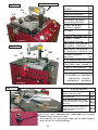
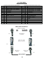
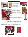
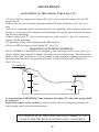
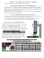
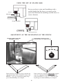
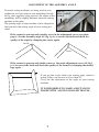
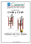
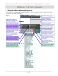
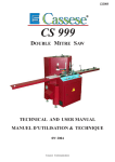
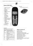
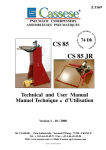
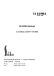
Z21514
PNEUMATIC UNDERPINNERS
CS199MXL
&
CS299MXL2
TECHNICAL & USER MANUAL
Version 3 05 / 2011
Cassese / Communication
WORK
Fig N° 1
POSITION
ANGLE ADJUSTMENT
Pr
CA
H
SCREW
AS
LEFT BACKFENCE
B2
RIGHT BACKFENCE
STAPLING BUTTON
B1
SB
LOCK BUTTON FOR
MB
STAPLING POSITION
AS
PG
VA
SB
M
CA
WIRE FOR WEDGE
PUSHING SPRING
F
CLAMPS
G1
G2
WEDGE DISTRIBUTOR
H
SLIDING TABLE
CS199MXL
BLOCKING LEVER
MB
BLOCKING LEVER FOR
Fig N° 2
STAPLING
BLOCKING LEVER FOR
2nd STAPLING POSITION
Po
G2
MB
B2
G1
POSITION
P2
CLAMP POSITION
TC
B1
BUTTON
F
PG
TOP PRESSER BRACKET Po
QUICK-CHANGE
MAGNETIC TOP CLAMPS Pr
ANGLE ADJUSTMENT
SLIDING TABLE
CA
P2
P1
RI
TC
CS 199MXL & CS299MXL2
PNEUMATIC FRAME
ASSEMBLING MACHINES
P1
CS199MXL
Fig N° 3
CS299MXL2
RId
REMOVABLE CLAMPS
RIg
BACKFENCES
BR
GE
CS299MXL2
GE
BR
LEFT ADJUSTMENT BUTTON
FOR THE INCLINATION OF THE
FENCES
RIg
RIGHT ADJUSTMENT BUTTON
FOR THE INCLINATION OF
THE FENCES
RId
BUTTON TO ADJUST THE PRESSURE OF THE HORIZONTAL CLAMPS.
Minimum allowed pressure is 2 bars.
To be used when you replace regular clamps with soft rubber clamps or
when you join very softwood moulding.
A
ACCESSORIES
ACCESSORIES SUPPLIED WITH THE MACHINE CS199MXL
QTY
Z 21 51 0
Z 1 338
Z 1 783
Z 1 791
Z 1 8065
Z 1 879
Z 1 884
Z 1 885
Z 1 896
Z 1 993
Z 21 500
Z 3078
Z 4857
Z506
Z 535
Z 556
Z 5897
Z 6532
Z 701
Z 749
Code
1
4
1
1
1
1
1
1
1
1
1
1
4
1
1
1
1
1
1
1
Désignation
ACCESSORIES SUPPLIED WITH THE MACHINE CS299MXL
QTY
S/ E ACCESSOR Y BOX CS1 99MXL
NU T HM 1 2
YELLOW R UBBER 30 MM 70 SHOR ESES
GR EEN R UBBER 30 MM 90 SHOR ESES
R UBBER SUPPOR T
ALLEN KEY 2.5
ALLEN KEY 4
ALLEN KEY 5
T UBE OF GR EASE
CAR T ON 240 X 1 70 X 50
ADJUSTABLE BUNG AXIS
SPACER BARS
D FOOT : 40 M1 2 X 50
SHOR T HAMMER
T OOL
STANDARD HOSE CONNECTOR M1/4 CYL
PLAST I C SACHET GR I P 8 X 1 2
BALL LOCK D: 8 X 40
USAGESES MALE FER R ULE M 1 / 4 TEFLONE
QUICK RELEASE FEMALE CONNECTOR 1 / 4
Z 21 51 1
Z 1 338
Z 1 783
Z 1 791
Z 1 800
Z 1 804
Z 1 8065
Z 1 879
Z 1 884
Z 1 885
Z 1 896
Z1993
Z21500
Z3078
Z 4857
Z506
Z 535
Z 556
Z 5897
Z 6532
Z 701
Z 749
Code
Désignation
1
4
1
1
1
1
S/ E ACCESSOR Y BOX CS299MXLP
NU T HM 1 2
YELLOW R UBBER 30 MM 70 SHOR ESES
GR EEN R UBBER 30 MM 90 SHOR ESES
YELLOW R UBBER 45 MM 70 SHOR ESES
GR EEN R UBBER 45 MM 90 SHOR ESES
R UBBER SUPPOR T
ALLEN KEY 2.5
ALLEN KEY 4
ALLEN KEY 5
T UBE OF GR EASE
CAR T ON 240 X 1 70 X 50
ADJUSTABLE BUNG AXIS
SPACER BARS
D FOOT : 40 M1 2 X 50
SHOR T HAMMER
T OOL
STANDADR HOSE CONNECTOR M1/4 CYL
PLAST I C SACHET GR I P 8 X 1 2
BALL LOCK D: 8 X 40
QUICK RELEASE US M 1/4 TEFLONE
QUICK RELEASE FEMALE CONNECTOR 1 / 4
1
1
1
1
1
1
1
1
4
1
1
1
1
1
1
1
AIR LINE FITTINGS
Advised way of fitting :
USA
Z675
STANDARD
Male Connector
on Machine
Z675
quick release (Q/R)
female air connector
Z749
Z749
Q/R US male
connector
Standard hose
connector
Z556
Z701
AIR SOURCE
B
CS199MXL & CS299MXL2
- USER’S
TECHNICAL MANUAL
CONTENTS
Page
INTRODUCTION
DESCRIPTIVE
ACCESSORIES SUPPLIED WITH THE MACHINE
TECHNICAL SPECIFICATIONS
OPTIONS
GUARANTEE
A
B
2
2
2
PUTTING INTO OPERATION
- Reassembly
- Connecting the machine to air supply
3
3
ADJUSTMENTS
- Adjustment of the sliding table
- Selection of stapling positions
- Setting and storing the stapling position
- Selection of top presser end
- Using the set of spacer bars
- Adjustment of the inclination of fences
- Adjustment of the assembly angle
4
4
5
6
6
6
7
USE
- Means of assembly
- Loading and changing the wedge cartridge on machine
- Joining the frame
8
8
8
MAINTENANCE
LUBRICATION
CLEARING OF A WEDGE STUCK IN THE WEDGE DISTRIBUTOR
IN CASE OF HAMMER AND WEDGE JAMMING
DISMOUNTING THE SLIDING TABLE
GENERAL ADVICE
TROUBLE SHOOTING CHART
Cassese Communication - 06 / 2008
9
9
10
11
11
12, 13
INTRODUCTION
You have just bought a Cassese Pneumatic Joining Machine, so we congratulate on your sensible choice and thank you for your trust in Cassese products.
These machines benefits from the experience of the joining machines that brought Cassese a
certain reputation. It makes it possible to join wooden mouldings of all profiles ( patent n°
7522814).
The CS underpinners are designed to allow the operator to move all around the machine.
The joining operation is carried out by using metal wedges especially designed to perform a
tight join. These wedges come in throw-away plastic cartridges, without glue, individually lubricated and rust-protected for the toughest challenges.
IMPORTANT : You should not use other wedge cartridges than those developed by Cassese
( registered mark CS)
TECHNICAL SPECIFICATIONS OF CS199MXL & CS299MXL2
-
Minimum moulding width : 5mm (3/16”) - maximum width : 130 mm (5¼”)
Minimum moulding height : 7 mm (¼”)- maximum height : 90 mm (3¾”)
Minimum dimensions of a frame : 85 mm x 85 mm visibly (3½” x 3½”).
Wedge sizes in cartridges of 275 pieces : 3, 5, 7, 10, 12 and 15 mm.
Two wedge types : for soft and for hardwoods.
Machine weight : 70 kg (155 lbs)
Dimensions : W 450 mm x L 490 mm (without optional rotating table)x H 1100 mm
Height of work table : from 900 to 930 mm ( following adjustment of the feet )
Pneumatic supply : compressed air 7 bar (100 psi),
Average consumption : 5 litres per cycle.
Air conditioning : air pressure reducing valve + manometer, connecting pipe, inside
diameter 8 mm.
OPTIONS
.
Independent rotating table, diameter 1300 mm (50¼”) to make the handling of large
frames easier (frame dimensions not exceeding table diameter).
Set of furniture clamps to join mouldings without rebate and/or small frames.
Angle inserts for 6-sided frames or 8-sided frames or other forms on request
GUARANTEE
One year guarantee for parts and labour against manufacturing defects. Wear parts and those
damaged as a result of non appliance with the instructions of the present manual are excluded
from the guarantee.
2
PUTTING INTO OPERATION
REASSEMBLY
Cut and remove the two ties
on the case. Remove the
ringfrom case. Clear the body
of case while pulling it
E1
upwards. With a flat key of 19
mm, remove the two nuts (E1,
E2) under the pallet.
E2
L
MANOMETER
Vg
Vdr
Remove the screws (Vdr,Vg) from the
removable front cover of the machine.
with a key allen of 4 mm. Make topple
the hood. Cut the L ring. While pushing
on the arm of pressor, remove the wood
piece CB . Loosen the arm of plunger
mildly.
CB
Reassemble the four feet of the machine supplied among
accessories.
Raise the machine from the pallet (watching out for the
pedal) and put it down on the floor.
Adjust the level of the machine to your floor so that the
machine vibrates or moves as little as possible (which is
one of the main cause of early wearing of the mechanical
parts)
CONNECTING THE MACHINE TO AIR SUPPLY
1) Inside the machine (see below), connect the compressed air inlet pipe by using the quick
release female connection supplied with the machine ( see page B ).
2) Tie up the air bleeding pipe to the compressed air pipe, passing through the opening located on the side of the base
cabinet, so that the air bleeding can be made outside the machine
2) Plug the air compressor and position the air valve (right side of the machine) to ON .
Make sure pressure in manometer is equal to 6 bars (85 psi).
Air bleeding
pipe
AIR
VALVE
Connection for quick release coupling
+ air supply
REMOVABLE FRONT COVER
3
ADJUSTMENTS
ADJUSTMENT OF THE SLIDING TABLE (Fig.1, TC)
1) Turn to ON the clamp position button PG ( fig1, pA) to make the clamps (G1 and G2)
move forward.
2) Make sure the two inclination adjustment knobs RI of the backfences (fig 1 pA) are at
zero.
3) Position a moulding against left hand fence B1 (for mouldings with a height smaller than
the fence, use the spacer bars supplied with the fittings by slipping them between the fences
and the small mouldings.
4) Move sliding table TC ( fig2 pA) forward as far as the clamp G1 ( fig1 pA) comes into
contact with the moulding.
5) Tighten the sliding table blocking handle MB (fig1pA).
6) Turn to OFF the clamp position button PG ( fig1, pA)
SELECTION OF STAPLING POSITIONS
The CS 199MXL & CS299MXL2 are designed to join mouldings in one or two places (positions) without limitation of the number of wedges in any of those places. The selection depends on the width and thickness of the moulding to join. If needed, additional positions can
be inserted between these two positions using the “LOCK BUTTON FOR STAPLING POSITION” (Fig 1 p A).
2 mm MINIMUM
2 mm MINIMUM
10mm
10mm
12 mm
10mm
As a general rule a MINIMUM 2 mm clearance (less than 1/8”) above the wedges shall
be respected.
Same sized wedges can be stacked in order to avoid to have to change the cartridge size
when joining frames with different thickness.
AS A GENERAL RULE, THE JOINING MUST BE CARRIED OUT AS
CLOSE TO THE THICKEST MOULDING PART(S) AS POSSIBLE .
4
SETTING AND STORING THE STAPLING POSITIONS
Unlock the stapling position lock handles P1, P2 ( fig2 pA).
For the stapling position close to the outside of the frame :
Press the button CA to unlock and slide the top presser bracket Po (fig2 pA) with your
right hand as far as the stapling position selected has been reached. The wedge distributor
H (fig1 pA) moves at the same time underneath of the moulding and its wedge exit slot
shows you exactly the position reached.
Holding the bracket in position with your right hand, slide with your left hand the handle
P1 forward in stop position and tighten it.
For the stapling position close to the inside of the frame :
Press the button CA again and slide the top presser bracket Po forward until it reaches the
position chosen for the insertion of the wedge(s) inner frame side.
Release now the button CA to lock the position and slide the handle P2 (fig3, p A) towards yourself until it reaches the stapling position chosen and tighten it.
1
SELECTION OF A TOP PRESSER END
1 top presser comes now with your machine as a standard
feature. It fits the plunger head thanks to the pin G and can
be set up in 1 to 7 positions from the table.
Pay attention to position well the triangle : the sides of the
triangle must be parallel to stops B1 and B2 (see fig1 page A)
BLACK TRIANGLE PRESSER
WHITE TRIANGLE PRESSER
GREEN RUBBER TIPS
YELLOW RUBBER TIPS
HARD WOOD
SOFT WOOD
HARD WOOD
SOFT WOOD
3
4
5
6
7
30 and 45 mm
30 and 45 mm
Triangle top pressers are good for flat mouldings or for
mouldings presenting a flat or horizontal area to come
down on. The round rubber ends are good for complicated
forms (uphill, downhill or reverse mouldings).
Pin (G)
2
Presser
Moulding
LOCATING THE TRIANGLE / ROUND RUBBER TOP PRESSERS
MAXIMUM HEIGHT FOR THE MOULDINGS
Position hole #
Rubber 30mm
1
2
3
4
5
6
7
13 mm
27 mm
42 mm
57 mm
71 mm
85 mm
100 mm
Quick-change magnetic top clamps
5
Rubber 45mm
/
13
27
42
57
71
85
mm
mm
mm
mm
mm
mm
Triangle
20 mm
35 mm
49 mm
63 mm
73 mm
92 mm
170 mm
USING THE SET OF SPACER BARS
In case you have to join small mouldings with a
smaller height than the fences, you must put the
spacer bars between the mouldings and the fences to
create a distance.
Presser
Moulding
INCORRECT
Fences
Wedge distributor
CORRECT
Set of spacer bars
ADJUSTMENT OF THE INCLINATION OF THE FENCES
SETTING SCREW FOR THE
ASSEMBLY ANGLE
ADJUSTMENT BUTTON FOR
THE INCLINATION OF THE FENCES
+
0
-
RI
If the corner has an opening underneath, turn the
same two adjustment buttons (RI) an identical
value to the PLUS (+) (fig 1 p A) until the opening disappears when mouldings are clamped.
If the corner has an opening on top, turn the two
adjustment buttons (RI) an identical value to the
MINUS (-) (fig 1 p A) until the opening disappears when mouldings are clamped.
6
ADJUSTMENT OF THE ASSEMBLY ANGLE
If several cutting machines are being used in your
production or if you receive your mouldings already
cut by your suppliers (chop service), the angles of the
mouldings will be slightly different from one cutting
machine to the other.
The joining angle of your machine can be adapted to
find precisely the cutting angle of your cutting machine.
ANGLE
ADJUSTMENT
SCREW
If the corner is open towards outside, screw in the adjustment screw (see photo
page 6 ) for the assembly angle AS (fig 1 p A) to correct the fault and check the
quality of the angle by clamping the corner again.
Outside
Inside
If the corner is open towards inside, unscrew the angle adjustment screw AS (fig 1
p A) to correct the fault and check the quality of the corner by clamping the mouldings again.
If you get this result, check your cutting angle, which is
wrong in this case because it is less than 45°.
Carry out the adjustment of the angle of your cutting
machine.
IT IS IMPOSSIBLE TO MAKE A RECTANGLE
FRAME WITH ANGLES SMALLER THAN 90°.
7
USE
MEANS OF ASSEMBLY
The joining is performed by using metal wedges, a Cassese invention, designed to ensure very tight corners. 7 sizes are available : 3, 5, 7, 10, 12
and 15 mm. They come in throw-away cartridges that are colour-coded per
size for easy identification. Cartridge wedges exist in two versions : NORMAL for soft and normal timbers and HW for very hard timbers. These hardwood wedges are to be used only on hardwoods. Your CS199MXL and
CS299MXL2 machines are designed to use all sizes of Cassese cartridges
without having to change any parts on the machine or having to adjust
anything.For the long term performance and reliability of your CS199MXL
and CS299MXL2 use only genuine CASSESE cartridge wedges.
LOADING AND CHANGING THE WEDGE CARTRIDGE ON MACHINE
Pull the wire with ball of the wedge pusher spring F (fig.3, p A) fully out. If there is a cartridge on machine,
holding the wire pulled out, remove it by simply sliding out the cartridge. Holding the wire pulled out, put a
new cartridge on machine and pay attention that it is fully inserted in the wedge distributor’s window. Release
gently the wire with ball of the wedge pusher spring F.
JOINING THE FRAME
1- After adjusting the sliding table, selecting and setting the stapling positions, selecting the best suited
top presser end, (see chapter : Selection of top presser end page 5)
2- Put the first moulding in front of the fence B1 and push it so that its mitre end reaches the other fence
B2. Holding it so, put the second moulding chop against fence B2 and slide it until it reaches the first moulding.
3- Holding the mouldings in place, push the foot pedal to clamp the mouldings and to check visually the
quality of your corner.
4- If needed, carry out the adjustment of the assembly angle and the inclination angle of the fences (see
pages 6, 7 ) to reach the best quality corner, before inserting wedges.
5- If the corner is satisfactory, maintain the foot pedal pressed during the whole work with this corner.
6- Press (unlock) the Lock Button CA (fig1 pA) and slide the top presser bracket to one of the stapling
positions chosen. Release (lock) the Lock Button CA and press the stapling button SB (fig.1 pA) to insert the
first wedge.
Keep the stapling button pushed until the end of the cycle.
If a second wedge must be inserted and stacked in the same position, release the stapling button and push it
once again. Keep the button pressed every time until the end of the cycle.
7- Slide the top presser bracket to the next stapling position and repeat point 4 above.
Nota: The removable clamps of the CS299MXL2 are in low position when the pedal is not used.
8
MAINTENANCE
BEFORE ANY MAINTENANCE INTERVENTION,
CLOSE THE AIR VALVE OF THE MACHINE
1) LUBRICATION
Periodically:
- Remove the cartridge that is on machine.
- Using the 3mm Allen key, loosen the locking screw of the wedge distributor Block H (page10).
- Remove it from the machine.
- Remove the four screws (A, B, C, D) and open the block H.
- Clean the wedge distributor
It is recommended to lubricate the hammer (driver blade) periodically. To do so, remove the wedge
distributor (block H) and put a small quantity of grease (a tube of grease is with accessories of the
machine) in the bottom hole of the wedge distributor. The hammer will be lubricated every time it
crosses the wedge distributor.
2) CLEARING OF A WEDGE STUCK IN THE WEDGE DISTRIBUTOR
If you release the stapling button during the cycle or if you lift the top presser bracket accidentally, a
wedge may be half engaged in the wedge distributor. In this case,
- Close the air valve.
- Try to remove the cartridge that is in position. If it resists, use the wedge removal tool to push
down the wedge back in the cartridge.
- Pay attention not to make penetrate the tool more than 6mm (¼”) into the wedge distributor.
- In case of the hammer (driver blade) jamming with a wedge in the wedge distributor, see the following section (3).
WEDGE REMOVING TOOL
6mm MAXIMUM ( 1/4’’ )
DISTRIBUTOR
( BLOCK H )
WEDGE EXIT
9
MAINTENANCE
BEFORE ANY INTERVENTION,
CLOSE THE AIR VALVE
3 ) IN CASE OF HAMMER AND WEDGE JAMMING
PLUNGER
WEDGE
DISTRIBUTOR
(BLOCK H)
A
SCREW
POSITIONS
BLOCK H
GF2
SLIDING
TABLE
BLOCKING SCREW
D
GF1
F
E
B
C
- Remove the cartridge that is on machine.
- Using the 3mm Allen key, loosen the locking screw of the wedge distributor Block H.
- Remove it from the machine.
- The old hammer (wedge driver blade) is stuck in the wedge distributor : first try to remove it
with a pair of pliers. If not possible, unscrew the two central screws (GF1, GF2) that hold the
fixed (square) guide of Block H in place. Use for this the smaller (2.5mm) Allen key supplied
with the machine. Remove the fixed guide completely to free the old hammer. If still not possible
to get rid of the old hammer, remove the four screws (A, B, C, D) and open the block H.
- Remove the old hammer. Assemble the Block H back again.
PUTTING A NEW HAMMER (DRIVER BLADE) :
- Put a drop of grease (tube of grease supplied with the machine) in the bottom hole of the wedge
distributor (block H).
- Insert a new hammer into block H with the hole of the hammer downwards.
- Re-position the wedge distributor in its housing on the machine with the window towards the
cartridge.
- If the upper end of the hammer stays out of the block H, push it fully in with a piece of wood or
moulding.
- Leave the moulding in place (on block H) and put any of the top presser ends on the machine
paying attention that the distance between the moulding and the top presser does not exceed
50 mm (2”).
- Turn on the air supply to the machine and without wedges make a simulation of assembly (press
foot pedal and press the stapling button during the whole cycle.)
The new hammer must have taken its position in the mechanism automatically.
Turn off the air supply.
- Check with your finger that the block H does not stay out of the machine (higher than the work
level) and tighten the locking screw of block H. No need to tighten too much.
- Turn on the air supply ; the machine is ready to work again.
10
4) DISMOUNTING THE SLIDING TABLE
If you need to dismount the sliding table to clean dust etc accumulated underneath, remove the
blocking handle MB of the sliding table ( fig 1 pA ) and clear the table while catching it by the
two adjustment buttons RI ( fig1 p A) of the fences inclination.
GENERAL ADVICE
If the hammer jammings are too frequent, it may be because of the use of not genuine Cassese
cartridges.
The use of other wedges than genuine Cassese cartridges causes frequent hammer jammings and
too fast mechanical ageing of your frame joiner.
For any other technical problems,
do not hesitate to contact
your favourite supplier of Cassese products or
Cassese Factory (France), Int’al Department
on Phone +33.1.64.42.49.71 or 72
Fax +33.1.64.42.58.94 or +33.1.64.06.04.19
11