1
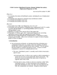
CS122 Lecture: Architectural Design; the MVC and Client/Server
Architectural Patterns
last revised March 17, 2015
Objectives:
1. To introduce architectural design
2. To introduce UML diagrams relevant to architectural design - component
diagram, deployment diagram
3. To introduce the use of packages
4. To discuss several architectural patterns Layered, MVC, Client-Server, Pipe
and Filter
Materials:
1.
2.
3.
4.
5.
6.
7.
8.
9.
Projectable of fig 9.7 in book
Projectable of another component diagram example
Deployment diagram projectables (UML User Manual pages 412, 415)
Projectable of figure 9.5 in book
Projectable of Java layered architecture
Projectable of alternative client-server architectures
Projectable of pipe-and-filter architecture
Projectable of pipe-and-filter structure of a compiler
Projectable of transaction-processing architecture
I. Introduction
A. There are many kinds of design that go into developing a software system.
Examples?
ASK
1. Architectural design
2. Class design
3. User interface design
4. Today we focus on architectural design.
1
B. The highest level of design is sometimes called architectural design.
1. We can speak of system architecture, which deals with the overall
structure of the system in terms of its subsystems and major components.
For example, consider the anti-lock brake system of a car. The purpose
of such a system is to prevent hard braking from locking the wheels,
which produces skidding.
Such a system consists of speed sensors for each wheel, a hydraulic valve
that can be used to reduce braking pressure when one or more wheels
lock up, and a software controller that senses when one or more wheels is
rotating considerably slower than the others, indicating that it is about to
lock up. In such a situation, the ABS controller pulses the hydraulic
valve to momentarily reduce braking pressure, thus allowing the wheel
that is about to lock up to turn again.
The major components of this system, then, are 4 wheel sensors, a
hydraulic valve, a microprocessor and software that runs on the
microprocessor.
2. If the system has many classes - as it often does - we may choose
to describe the system by using packages of related classes rather
than showing the individual classes. (The examples we will do in
this lecture use this approach)
Quick-Check Questions d, e
C. In any sort of design, one key thing we need to do is to partition a
larger problem into smaller pieces. (The divide and conquer
principle). At the system architectural level, the pieces go by different
names, depending on what is actually involved:
1. A component is a piece of an overall system that has a clear role,
can be isolated, and can, in principle, be replaced with a different
component that provides the same functionality. A component may
be software, hardware, or both.
2
Examples:
a) A hardware device like a computer’s monitor is a component.
b) A web-browser is a component.
c) In designing software, a key concept is the notion of a re-usable
component, which is simply a component that can be “plugged
in” to different problems
Thus, in our ABS example, the components are the wheel speed
sensors, the hydraulic valve, and the software running on the
ABS Controller system.
2. A system is a collection of components that work together to do
some job. Complex systems are often composed of definable
subsystems, which have internal structure of their own.
(Sometimes the term “system” is limited to just hardware and
software, but other times the term is used more broadly to
encompass people, processes, organizational structures etc.)
In our ABS Controller example, it is likely the case that the wheel
sensors and hydraulic valve are subsystems which might
themselves be further analyzed.
3. When a system is geographically distributed, the subsystem at a
particular location is often called a node.
3
II. UML Diagrams Relevant to Architectural Design
UML has two kinds of diagrams that are useful at this level.
A. A component diagram shows the major software components of a
system and their relationships.
QC Question f
1. Figure 9.7 in the book is an example of a component diagram.
PROJECT
2. Another example: A typical structure for an e-commerce site is as
follows: the web server houses a database of information about the
company’s products. When a customer request is received, it generates a
dynamic web page which it sends to the customer’s browser, based on a
template stored on the server. (E.g. if the customer submits a search
request, the server software searches the database and creates an
appropriate search results page based on a template for such pages.) This
can be depicted as follows (using UML 1 notation, which is the notation
used in the book - UML 2 is different)
PROJECT
Dynamic
Web
Page
Server
Software
Web
Page Web
PageWeb
Template
Page
Template
Template
4
Database
B. A deployment diagram shows the major hardware components of a system
and their relationships, and also indicates which software components are
allocated to each hardware component. It is particularly useful for use
with distributed systems, in which the hardware components are located at
different places.
QC Question g
1. The major components of a deployment diagram are nodes - symbols
representing either a processor or some significant piece of hardware
that the system utilizes. The standard symbol for a node is a cube:
a) Nodes representing specialized pieces of hardware can be represented
by specialized symbols, as we shall see shortly.
b) Nodes are connected by associations, representing the flow of
information back and forth between them.
c) We may also explicitly show the network which allows the nodes to
communicate, if they communicate via a general-purpose network
rather than via dedicated hard-wired connections.
d) Note that, in contrast to other diagrams we have drawn, in a
Deployment diagram the symbols represent hardware - not software.
(The software is deployed on one or more processors, depicted by
node symbols.)
2. Deployment diagrams can be used to depict several different types of
systems:
5
a) Embedded Systems
(1) An embedded system is one in which a computer is embedded in
some piece of physical equipment to control it (e.g. a home
appliance, a car, or a chemical plant)
(2) The following example appears in the UML User Manual,
depicting an embedded system controlling an autonomous robot
PROJECT: UML User Manual page 412
Note that there is only one processor - the remaining nodes are
specialized hardware controlled by software in the processor.
Note also the used of specialized symbols for these nodes - chosen
ad-hoc to help the reader understand the diagram. (These are not
standard UML symbols!)
(3) We could depict our ATM example system using such a diagram to
depict the various specialized pieces of hardware in relationship to
the controlling processor that runs the software we have discussed
in previous lectures. Note that, in this case, we are depicting
hardware - not the software that controls the hardware. (E.g. in
previous discussions, we have used a class CardReader to represent
the software that controls the physical device that reads ATM
cards. In this diagram, that class is part of the software that is
deployed on the processor that controls the system, and the card
reader symbol stands for the physical hardware device it controls.)
ASK FOR A VOLUNTEER TO PRODUCE SUCH A DRAWING
ON THE BOARD.
b) Client/Server Systems - which we will discuss more fully shortly
A quick Example: Our ATM system (viewed now as a node)
connected to the bank’s computer.
ASK FOR A VOLUNTEER TO PRODUCE SUCH A DRAWING ON
THE BOARD.
6
c) Fully-Distributed Systems
Example: PROJECT - UML User Manual page 415
Note how the Internet is depicted, potentially connecting any console
to any regional server, while direct hard-wired connections between
specific servers are shown as associations.
3. A Deployment diagram is not required for the VideoStore example
system, as specified.
a) The system we have been designing thus far has been designed,
presumably (but perhaps unrealistically), to run on a single computer
b) Suppose, however, that we were to design it as a distributed system perhaps with several clerk consoles (computers), and perhaps some
kiosks that customers can use to make inquiries. What might such a
system look like?
ASK
DEVELOP A DEPLOYMENT DIAGRAM AS A CLASS.
Some options to consider
(1) Server - perhaps a separate system
(2) Manager console - perhaps a separate system, or server system
could double in this capacity.
c) Note: for purposes of the project, do not attempt a distributed
implementation!
7
III.Architectural Patterns
A. It turns out that there are a variety of architectural design patterns that
are appropriate for different situations.
B. The book talked about another such pattern, which can be used both
for hardware/software systems and for understanding purely software
systems.
ASK
Layered architecture
QC Question h - then pick up QCs
1. In a system using a layered architecture, the system is organized
into layers.
a) A given layer may only directly depend on the services
provided by the layer immediately below it.
b) Each layer defines an interface representing services it makes
available to the next layer up.
2. Example: The book discussed a four layer architectural pattern that
is quite common
PROJECT Figure 9.5 from book
3. Example: Java implementations typically use a layered architecture
that looks like this:
PROJECT
8
Java Bytecodes (.class files)
Java API
JVM Implementation and
native classes
Platform
(Native Operating System
and Physical CPU)
a) A JVM implementation is specific to a particular platform. It
depends on the facilities of the native operating system, and is
capable of executing any standard java class file.
b) The bytecodes produced by the javac compiler (and the API routines
in the java. and javax. packages in the system library) depend only on
the standard java class file format Thus, the same class files will run
on any java implementation, regardless of the platform.
4. Layered architectures are not confined to software. Layering is
also used in systems comprised of software and hardware - e.g.
there is a model for understanding computer networks called the
ISO/OSI model which has seven distinct layers - several of which
involve both software and hardware.
The lowest layer is the physical layer- the physical means by which
bits are transmitted from one place to another. A physical link can
be something like ethernet, or fiber optics, or wireless. Higher
layers should be unaffected by what choice is made at this layer,
though. One manifestation of this is that a computer that is
connected to a network via a wired connection can be seamlessly
shifted to a wireless connection.
9
C. The student registration system that has been the basis of a couple of
labs you have done/you and the starter software I gave you for the
Video Store project are based on another architectural patttern, called
the Model View Controller architectural pattern that is used
extensively is the Model-View-Controller (MVC) architecture. Many
GUI applications follow this pattern - often at multiple levels
Model
updates
notifies
about
changes
Controller
interacts
with
View
informs of actions
1. It has some key benefits in terms of producing a cohesive system
a) Classes in each part of the system perform different sorts of tasks.
(1) Classes in the model serve to represent entities that the system
manipulates. Each class has, as its single task, representing some
one kind of entity.
(2) Classes in the view allow users to interact various aspects of the
system - e.g. a specific entity, or a specific body of information,
displaying information and receiving user requests.
(a) When something in the model changes, it notifies the view
(b) When an actor requests an operation in the view, it notifies the
controller
10
(3) Classes in the controller represent various tasks (use cases) that the
system performs, by updating the view in response to user requests
b) Each part of the system, then, focusses on one type of thing:
(1) The model focusses on representing information.
(2) The view focusses on displaying information.
(3) The controller focusses on carrying out user commands on
information.
c) Note that this is not a layered architecture, because the View depends
on both the Model and Controller layers.
2. Both the registration system you worked with in lab and the video store
starter code I gave you actually have three packages called model, view,
and controller. (However, the “notifies about changes” dependency is not
realized, because it would require use of a design pattern you don’t know
about yet. We will talk about something like this might be done when we
discuss the Observer design pattern in the next series of lectures.)
3. Can you think of an example of a system (other than the video store, of
course) that uses this architecture?
ASK
The AddressBook System
a) What classes constitute the model?
ASK
AddressBook, Person, FileSystem
b) What classes constitute the view?
ASK
AddressBookGUI, MultiInputPane
11
c) What classes constitute the controller?
ASK
AddressBookController (also AddressBookApplication)
d) It is also possible to construct a simplified class diagram in which
special symbols are used to denote entity classes (generally found in
the model), boundary classes (often found in the view) and controller
classes.
PROJECT AddressBook “Further Analysis” page
4. This basic structure is also used internally in Swing e.g., though
Swing is used for the view part of an MVC system, internally it
makes use of distinct models.
a) Note interfaces whose name ends with Model in the Swing
documentation
SHOW
b) Go through description in the documentation for
(1) ListModel
(2) ComboBoxModel
(3) ButtonModel
c) For each interface, Swing supplies a default implementation
that is used in most cases (though you can produce your own if
necessary).
SHOW Default implementations for the above in
documentation
D. Another pattern is the client-server architecture - a pattern that occurs
over and over in Internet applications.
12
1. In the simplest case, a client-server system consists of a server
system and (one or more) client subsystems. For example, a web
browser relates as a client to a web server; the mail program
running on a personal computer acts as client to a mail server, etc.
2. More complex systems can be understood in terms of a layered
model: a user-interface layer, a business-logic layer, and a database
layer. For example, many e-commerce systems are set up this way:
the user interface layer is a web page (perhaps with embedded
javascript) viewed by a web browser; the business-logic layer is the
software that provides information in response to user requests and
processes orders, and the database layer stores information about
the products and records user orders. There are three different
ways these might be distributed:
PROJECT
a) An approach often used by e-commerce systems (the so-called
“thin client” approach)
User-interface layer
Client System(s)
Business-logic layer
Server System
Database layer
b) The so-called “thick client” approach, used when it is desirable
to install the business logic software on the client system (This
wouldn’t work for e-commerce, of course, but is sometimes
used for specialized applications)
13
User-interface layer
Client System(s)
Business-logic layer
Database layer
Server System
c) A three-layer approach that can also be used as an alternative to the
thin client approach. (Note that the client would never see any
difference between this approach and the thin-client approach; in
fact, many e-commerce systems are in fact built this way)
Client System(s)
User-interface layer
“Visible”
Server System
Business-logic layer
Database
Server System
(Invisible to
clients)
Database layer
14
3. While the client-server architecture is most commonly seen in
distributed systems, it can also be used for software systems running
on a single computer - e.g. a program that uses a relational database
is often structured as a client relating to a separate database server
program running on the same computer. (In fact, a database server
program running on a computer may simultaneously be serving
several different clients on that same machine.)
E. An alternative architecture for distributed systems is a Peer-to-Peer
architecture in which there is no designated server as such. Instead,
each participating system can function either as a client, or as a server
to some other system.
F. Another architectural pattern is the “Pipe and Filter” Pattern. In this
approach, a system is organized as a collection of subsystems called filters.
The overall input to the system flows into the first filter, which performs
some transformation on it and sends the transformed data to the second filter,
which performs a further transformation on it and sends it to the third
filter ...
PROJECT
Raw
Input
Filter 1
Filter 2
Filter 3
•••
Filter n
Final
Output
1. One place where this architecture is often used is compilers. Thus,
a simple compiler might be organized like this:
PROJECT
Source
Program
(stream of
characters)
Tokenizer
Stream of
Tokens
Parser
Parse
Tree
Code
Generator
(More sophisticated compilers include various code-improvement
(so-called “optimization”) steps which may be inserted either
between the parser and the code generator, or after the code
generator - or often both)
15
Object
Program
2. Another place where pipe and filter architecture is often used is in
systems that process signals such as sounds (e.g. speech
recognition systems.) In fact, the term “filter” really comes from
the world of hardware signal-processing systems.
16