1
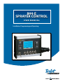
844-E
Sprayer Control
U se r M AN U AL
Installation, Programming and Operating
844-E Sprayer Control
Table of Contents
Chapter 1 - introduction
1
Chapter 2 - Mounting Sprayer Components
2
Pressure Regulator in Bypass Mode................................................................................................................................................................ 2
Pressure Regulator in Throttling Mode.......................................................................................................................................................... 3
Flow Meter............................................................................................................................................................................................................... 4
Boom Control Valves............................................................................................................................................................................................ 4
Pressure Transducer.............................................................................................................................................................................................. 4
Installing the Speed Sensor Assembly
5
Components...................................................................................................................................................................................5
Speed Step 1 - Location....................................................................................................................................................................................... 5
Proximity Sensor (optional).............................................................................................................................................................5
Speed Step 2 - Installing The Wheel Magnets............................................................................................................................................. 6
Speed Step 3 - Installing the Magnetic Sensor........................................................................................................................................... 6
Speed Step 4 - Confirming Speed Sensor Installation............................................................................................................................. 7
Magnetic Wheel Sensor..................................................................................................................................................................7
Radar..............................................................................................................................................................................................7
Mounting The TeeJet 844 Console
7
Console Step 1 - Location................................................................................................................................................................................... 7
Console Step 2 - Mounting................................................................................................................................................................................ 7
Console Step 3 - Power Connection............................................................................................................................................................... 8
Console Step 4 - Connecting Component Cables..................................................................................................................................... 9
Connect Step 1 - Wiring Layout......................................................................................................................................................................10
Connect Step 2 - Making The Connection..................................................................................................................................................11
Chapter 3 - Programming
13
Important Preliminary Information..............................................................................................................................................................13
Steps to Successful Programming.................................................................................................................................................................13
System Setup Mode
14
Program Units.......................................................................................................................................................................................................14
Setting Your Program Mode (U.S., Turf, NH3, Imperial, S.I.)........................................................................................................14
Reset Defaults.......................................................................................................................................................................................................14
Reset To Default Settings.............................................................................................................................................................14
Sensor Type............................................................................................................................................................................................................14
Flow Meter or Pressure Based.....................................................................................................................................................14
Flow Meter Calibration......................................................................................................................................................................................14
Flow Meter Pulses........................................................................................................................................................................14
Pressure Transducer............................................................................................................................................................................................15
Maximum rating (P Hi)..................................................................................................................................................................15
Low Pressure Calibration (P rEF).................................................................................................................................................15
Nozzle Spacing.....................................................................................................................................................................................................15
Tips Per Boom Section.......................................................................................................................................................................................15
Number of Spray Tips Per Boom Section.....................................................................................................................................15
ii
www.teejet.com
844-E Sprayer Control
User Program Tip.................................................................................................................................................................................................16
User Programmable Tip................................................................................................................................................................16
Pressure Regulation............................................................................................................................................................................................16
Pressure Regulation Mode...........................................................................................................................................................16
Regulation Adjustment Speed.......................................................................................................................................................................17
Control Valve Type...............................................................................................................................................................................................17
Boom Control Valve Type: 2-Way/3-Way......................................................................................................................................17
Calibrate Speed....................................................................................................................................................................................................18
Speed Sensor Calibration.............................................................................................................................................................18
Proximity/Magnetic Pulses............................................................................................................................................................18
Automatic Calibration............................................................................................................................................................18
Manual Calculation:..............................................................................................................................................................18
Radar Speed Pulses.............................................................................................................................................................................................18
Automatic Calibration:...................................................................................................................................................................18
Manual Calculation:..............................................................................................................................................................18
Distance Counter.................................................................................................................................................................................................19
Simulated Ground Speed.................................................................................................................................................................................19
Program Specific Gravity...................................................................................................................................................................................19
Liquid Specific Gravity (Density)....................................................................................................................................................................19
Communications.................................................................................................................................................................................................20
Minimum Pressure..............................................................................................................................................................................................20
Minimum Regulating Pressure Setting.........................................................................................................................................20
Application Setup Mode
20
Target Application Rate.....................................................................................................................................................................................20
Nozzle Selection...................................................................................................................................................................................................21
Required Speed to Achieve the Application Rate.................................................................................................................21
Calculation Troubleshooting...........................................................................................................................................................................22
Adjust Speed:...............................................................................................................................................................................22
Adjust Pressure:...........................................................................................................................................................................22
Liquid Density:..............................................................................................................................................................................22
Chapter 4 - Operating Instructions
23
Sprayer Checkout................................................................................................................................................................................................23
The Spraying Operation....................................................................................................................................................................................23
Chapter 5 - Features
24
Boost Mode............................................................................................................................................................................................................24
Area/Volume Feature.........................................................................................................................................................................................24
Flow Rate Feature................................................................................................................................................................................................24
Application Alarm...............................................................................................................................................................................................24
No Flow Alarm......................................................................................................................................................................................................24
Printing....................................................................................................................................................................................................................25
chapter 6 - Troubleshooting Guide
26
98-70006-ENUS R4
iii
844-E Sprayer Control
Chapter 7 - Flow meter Calibration
29
Method 1 – Known Volume.............................................................................................................................................................................29
Step 1 – Known Value..................................................................................................................................................................29
Step 2 – Programming Calibration Number..................................................................................................................................29
Step 3 – Resetting Volume Counter.............................................................................................................................................29
Step 4 – Spraying Known Volume................................................................................................................................................29
Step 5 – Entering in New Flow meter Calibration Number...........................................................................................................29
Step 6 – Double-checking the New Value....................................................................................................................................29
Method 2 – Known Tip Size Method.............................................................................................................................................................29
Step 1 – Check Tip Size...............................................................................................................................................................29
Step 2 – Count Tips......................................................................................................................................................................29
Step 3 – Calculated Flow..............................................................................................................................................................29
Step 4 – Measure.........................................................................................................................................................................30
Step 5 – Adjustments....................................................................................................................................................................30
Copyrights
© 2013 TeeJet Technologies. All rights reserved. No part of this document or the computer programs described in it may be reproduced, copied,
photocopied, translated, or reduced in any form or by any means, electronic or machine readable, recording or otherwise, without prior written
consent from TeeJet Technologies.
Trademarks
Unless otherwise noted, all other brand or product names are trademarks or registered trademarks of their respective companies or organizations.
Limitation of Liability
TEEJET TECHNOLOGIES PROVIDES THIS MATERIAL “AS IS” WITHOUT WARRANTY OF ANY KIND, EITHER EXPRESSED OR IMPLIED.
NO COPYRIGHT LIABILITY OR PATENT IS ASSUMED. IN NO EVENT SHALL TEEJET TECHNOLOGIES BE LIABLE FOR ANY LOSS OF
BUSINESS, LOSS OF PROFIT, LOSS OF USE OR DATA, INTERRUPTION OF BUSINESS, OR FOR INDIRECT, SPECIAL, INCIDENTAL, OR
CONSEQUENTIAL DAMAGES OF ANY KIND, EVEN IF TEEJET TECHNOLOGIES HAS BEEN ADVISED OF SUCH DAMAGES ARISING FROM
TEEJET TECHNOLOGIES SOFTWARE.
iv
www.teejet.com
844-E Sprayer Control
Chapter 1 - introduction
Congratulations! And thank you for choosing TeeJet Technologies’ advanced 844-E sprayer control system. With its proper installation and
maintenance, you can enjoy many seasons of accurate and uniform spray application with fingertip convenience and ease of operation.
Installation and Programming of your control system will be covered in easy to follow, step-by-step instructions.
WE RECOMMEND THAT YOU READ THESE INSTRUCTIONS COMPLETELY
before attempting installation and programming of your 844 sprayer control. The unit’s performance will depend on its proper installation
and programming, along with planned preventative maintenance of your entire sprayer.
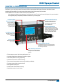
Easily Accessible
Programming Mode
Aluminum Console Housing
with sealed computer switch panel
resists electronic interference and
damage through rough handling for
years of reliable service.
is very user-friendly. The
process is made simple
with a series of easyto-follow, symbol-driven
programming steps.
A Large, Backlit Display
continuously displays all vital spraying
functions. With a quick glance, the display
reveals the application rate (automatically
switches between target and actual),
pressure, speed, and area covered.
Auto/Manual Control
gives the operator a manual
application option for failsafe reliability.
Master Shutoff
controls all boom sections
with one switch.
Individual Boom Controls
give independent control of up to five boom sections,
allowing better management of varying field features
like waterways and terraces.
Color-Coded Tip Selection Bar
allows for easy user programming by
matching the color of TeeJet VisiFlo®
spray tips.
• Full-featured sprayer control with industry-leading ease of use
• Large back-lit display shows all spraying information at a glance
• Color-coded tip selection for easy programming
• Communication Port for PC and GPS interfacing
• Flow or pressure based regulation options provide reliability and flexibility
• Five boom section switches plus master shutoff
• Built in application planning tool
• Durable, weather-resistant aluminum housing
• Single cable connection for quick hookup
98-70006-ENUS R4
1
844-E Sprayer Control
Chapter 2 - Mounting Sprayer Components
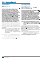
Pressure Regulator in Bypass Mode
All pressure regulating valves for the 844 will be wired for use in a bypass system. While plumbed in a by-pass mode, with the Auto/Manual
key in the “MAN” mode, the valve should close when the Plus key
is
pressed and open when the Minus key
is pressed.
The pressure regulating valve can also be mounted in a throttling
situation as an alternative location. Refer to pages 3 and 4, and Figures
3 and 4.
NOTE: The diagrams in Figures 1 and 2 are shown as general
guidelines to follow when plumbing the 844 components. The
type of pump used and location of other components can
vary from sprayer to sprayer. It is important to ensure that if a
pressure transducer is used, it is located as close to the spray
tips as possible. Normally, this is at the boom control valves.
However, if one particular boom section is always used, the
pressure transducer can be mounted on that particular boom
section. If a flow meter is used, make sure that all of the flow
going through the flow meter is directed to the spray tips. Make
sure that proper distance is allowed on the inlet and outlet side
of the flow meter (refer to Figures 2 and 3).
Figure 1: Bypass Plumbing Diagram - Pressure Based System
2
www.teejet.com
844-E Sprayer Control
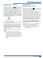
Figure 2: Bypass Plumbing Diagram - Flow Based System
Pressure Regulator in Throttling Mode
The pressure regulating valve, as shown in the figures below, can be located in the supply line before the boom control valves. If you choose this
location, the 844 will need to be properly programmed to reverse the polarity of the valve. This step can be found in the System Setup instructions
on page 14. When in throttling mode, the valve should open when the Plus key
is pressed, and close when the Minus key
is pressed. Be
sure to check this before plumbing the valve into the system.
Figure 3: Throttling Plumbing Diagram - Flow Based System
98-70006-ENUS R4
3
844-E Sprayer Control
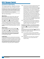
Figure 4: Throttling Plumbing Diagram - Pressure Based System
Flow Meter
To ensure accurate readings, the flow meter (if used) must be mounted
10″ to 12″ (25-35 cm) from other pipe fittings, preferably in a vertical
position with the flow going up. It should also be mounted with the
direction of flow arrow pointing toward the boom control valves. Refer to
Figures 2 and 3.
Be sure the flow meter is plumbed so that all liquid passing through it
is routed to the booms and not back to the tank. When using three-way
boom control valves, refer to page 13 of this manual for programming
guidelines.
Pressure Transducer
The pressure transducer (if used) should be installed as close to
the spray tips as possible. Normally this is at the boom control valve
assembly. Refer to Figures 1 through 3. Mount the unit vertically on a
short stand pipe to help protect the sensor.
NOTE: Pressure drop, to some degree, is found in most plumbing
systems. Pressure drop is created when there is any kind of
restriction in the spray line that reduces flow rate and is quite
often produced between the boom control valve assembly and
the spray tips. If one of the boom sections on the sprayer is
always used, the pressure transducer can be installed on that
particular boom section, minimizing any potential pressure drops
between the sensor and spray tips. If the pressure drop in your
system is greater than 5 psi (0.3 bar), you should consider this
as an alternative location for the pressure transducer.
Check all components to make sure they are mounted securely to avoid
excessive vibration.
Boom Control Valves
The Boom Control Valves are connected in tandem and centered in
front of the boom sections. See the Control Valve Instruction Manual for
mounting instructions. If using three-way valves, refer to the instruction
manual of the valves you are using for valve calibration instructions.
4
www.teejet.com
844-E Sprayer Control
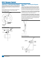
Installing the Speed Sensor Assembly
Components
Two (2) magnets, Sensor with attached connector cable, and mounting
hardware. If you are installing a radar ground speed sensor, follow the
instructions supplied with that unit.
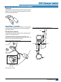
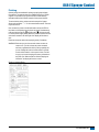
Speed Step 1 - Location
The speed sensor assembly should be installed on a non-driven wheel
to avoid potential errors that are likely to occur from a slipping drive
wheel. Refer to Figure 5.
Figure 6: Wheel Mounting of Magnetic Speed Sensor
CABLE
Proximity Sensor (optional)
An optional proximity sensor is available to use in cases where space
is limited or for drive shaft mounting.
The proximity sensor will work by sensing any metal object. The
proximity sensor must be mounted so that the sensor face is within 1/8″
to 3/8″ (3-10 mm) of the metal object being read.
Figure 5: Wheel Mounting of Speed Sensor
MAGNET
SENSOR
RIM
TIRE
NOTE:
TARGET FACES
TIRE LUGS
Note: Target faces tire lugs
98-70006-ENUS R4
5
844-E Sprayer Control
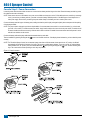
Speed Step 2 - Installing The Wheel Magnets
Check for pre-drilled holes in the wheel rim. If pre-drilled holes are not
available, layout a pattern as shown in Figure 7 and drill two 3/8″ (10
mm) holes near the outer edge of the rim if possible, and 180° from
each other.
Place the magnets into each of the two holes on the inside rim and
securely fasten them using the nuts and washers provided.
Figure 7: Magnet Locations
WHEEL
Speed Step 3 - Installing the Magnetic
Sensor
The flat, pressed L bracket of the wheel speed sensor kit should be
secured to a vertical member near the non-driven wheel. The round,
right angle steel bracket is then secured to the flat bracket with the
two U-bolts and necessary hardware provided. The round, right angle
bracket is then used to secure the magnetic sensor mounting clamp.
The magnetic sensor should be inserted into the mounting clamp and
positioned within 1/8″ to 3/8″ (3-10 mm) of the wheel magnet. Tighten
the sensor clamp using the clamp screw per Figure 10.
Your installation will likely vary from the example. It may be necessary
to customize the installation to accommodate your specific machine.
Keep in mind that the two magnets must be spaced an equal distance
around the wheel. The magnetic sensor must be mounted in-line with
the magnets and positioned within 1/8″ to 3/8″ (3-10 mm) from each
magnet as they pass the Sensor assembly.
Figure 9: Sensor Mounting
TIRE
3/8˝ (10 mm)
HOLE FOR
MAGNET
Figure 8: Magnet Assembly
MAGNET
NUT
WASHER
NUT
Figure 10: Sensor Assembly
FLAT
L BRACKET
BRACKET
SENSOR
CLAMP
SCREW
6
www.teejet.com
844-E Sprayer Control
Speed Step 4 - Confirming Speed Sensor
Installation
Magnetic Wheel Sensor
After your wheel or proximity sensor is installed and once the 844
console is installed and powered up, you can test the speed sensor
installation. Connect the wheel speed or proximity sensor to the sensor
cable, and in turn connect the sensor cable to the 844 console. When
the connection is made, rotate the wheel on which the magnets are
installed. If using a proximity sensor, you will be sensing metal objects
and not magnets. Each time a magnet (metal object for proximity
sensor) passes the sensor a red LED (orange LED for proximity
sensor) on the back of the sensor will light. The LCD display on the
console will also indicate a speed as the sensor receives and sends
electronic pulses.
Radar
Mounting The TeeJet 844 Console
Console Step 1 - Location
Determine the best location for the control console in the cab or
operator’s compartment. Allow sufficient clearance, approximately 4-5″
(10-12 cm) to accommodate for the cable that will be connected to the
right side of the console.
Console Step 2 - Mounting
Mount the console to a firm support within the cab area, and secure
using the slots provided on the top, back, or bottom of the Console.
Although two simple brackets are supplied with the unit, some
additional bracketing may be necessary. The slots in the 844 will accept
1/4″ (6 mm) bolts.
Figure 11: Brackets Provide Angle Adjustment
If you are using a radar speed sensor it should be connected to the
speed sensor connector on the sensor end cable. An adapter cable
will be necessary when using most radars and are available through
your TeeJet Technologies dealer. The 844 will automatically sense if
the speed sensor is a wheel speed, proximity type or radar type sensor
during calibration. The 844 is automatically adapted to most brands
of radar speed sensors provided that the appropriate adapter cable
is used. If using a radar sensor, the 844 will display rAd during the
calibration procedure.
98-70006-ENUS R4
7
844-E Sprayer Control
Console Step 3 - Power Connection
Locate the power cable that has a black connector on one end and two battery terminal rings on the other. Extend the battery terminal ring end of
this cable from the cab to the battery.
NOTE: Some tractors use two 6 Volt batteries as a power source. Make sure there are a total of 12 Volts delivered to the controller by connecting
to the (+) terminal on one battery and the (-) terminal on the other battery. Reliable operation of the 844 Sprayer Control depends on a
clean power supply. Ensure this by connecting the power cables directly to the battery and not to another power source.
Connect the battery terminal rings to the battery posts, making sure that the positive (red) and negative (black) wires correspond with the polarity
of the battery terminals.
NOTE: The power cable is designed to provide the simple addition of a remote master boom switch in a convenient location (i.e. on the throttle,
gear shift, or floor switch). To install a remote boom switch, simply install a switch to the brown wire in the power cable. The switch should
be rated to handle the total current used by all boom section valves combined. If installed, the remote master switch will operate in series
with the boom switches on the console.
Connect the battery cable to the power cable lead that extends from the main cable.
Test the installation by pressing the Program key
correctly.
once to turn the 844 console on. If the display shows information, you have wired the power
NOTE: The TeeJet 844 Sprayer Control has an automatic power down feature. With the master boom switch in the “off” position, the 844 will
automatically shut down after 10 minutes of no inputs. This prevents possible battery drainage. To turn the console “off” with the Master
Switch located in the “off” position, press and hold the Minus key
while pressing the Program key
once, and then releasing both
keys. The console will shut down providing no other keys are pressed.
Figure 12: Power Connection
8
www.teejet.com
844-E Sprayer Control
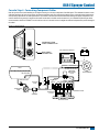
Console Step 4 - Connecting Component Cables
Now that you have the console installed you can begin connecting it to the other components of the 844 system. The standard kit contains a main
cable that attaches to the boom control valves, the pressure regulating valve, flow meter and/or pressure sensor, a magnetic wheel speed sensor,
and a proximity speed sensor or radar speed sensor. Lay out each of the valve and sensor leads before installing the sprayer components to be
sure the cables are long enough in length from the sensor connections to the 844 console connection. If your installation requires longer cables,
several extension cables are available. If an exit hole has to be cut in the cab, be sure the edges are deburred and protected to prevent damage to
the cables.
Figure 13: Wiring Diagram
COMMUNICATION
CABLE CONNECTION
POWER
MAIN CABLE
CONNECTION
844 SPRAYER CONTROL
TANK
PRESSURE
REGULATING
VALVE
JET AGITATOR
SPEED SENSOR
5-7˝
(12-17 CM)
TANK SHUT-OFF
FLOW METER
(IF USED)
AGITATOR
VALVE
10-12˝
(25-35 CM)
CENTRIFUGAL
PUMP
PRESSURE
TRANSDUCER
STRAINER
SOLENOID VALVES
(IF USED)
BOOM SECTIONS
98-70006-ENUS R4
9
844-E Sprayer Control
Connect Step 1 - Wiring Layout
Determine the best cable routing to the sprayer control components on the sprayer. This may be along the flow line, main frame of the sprayer, or
wherever the cables can be conveniently secured. Avoid any situation where the cables may lay in puddles, or come in contact with extreme heat
sources.
Warning: System Components should be mounted at least 3 ft / 1 m from areas of excessive vibration (i.e. engines) to avoid high frequency
interference.
Figure 14: Wiring Layout
10
www.teejet.com
844-E Sprayer Control
Connect Step 2 - Making The Connection
Now, extend the cable leads to the Flow meter or Pressure Sensor, and Wheel Sensor or Radar Sensor to the furthest component. Select the
appropriate lead and connect to this component. Run the cable to the other component, taking care to safely secure the cable along the route.
Refer to the diagram on page 10.
Repeat this procedure with the cable leads to the Pressure Regulating Valve and the Boom Control Valves. Refer to the chart below when
attaching the boom section wires. T-tap connectors must be attached to the +12vDc and ground wires to connect them to the boom control valves
(when using ball valves), which should be evenly distributed across the two.
If both the flow meter and pressure transducer are not used simultaneously, there will be one extra connection on the cable. Simply tie this part of
the cable back as it will not be used.
When all connections have been made, connect the large plug into the side of the Control Console.
Figure 15: Console Connector
Console Connector
Pin No.
Wire Color
Signal Name
B
White
Section 1
C
Brown
Section 2
D
Green
Section 3
E
Yellow
Section 4
F
Gray
Section 5
R
White
Flow Signal
S
White
Pressure Signal
T
White
Speed Signal
V
Brown
Power Out
a
White
Regulation Valve (+)
b
Brown
Regulation Valve (-)
c
Blue
+12 VDC
d
Blue
Pink
Ground Free End (Valves)
e
Red
Black
+12 VDC Free End
Pin No.
Wire Color
Signal Name
1
Brown
+12 VDC (Computer)
2
Blue
+12 VDC (Valves)
3
Yellow/Green
Ground
Pin No.
Wire Color
Signal Name
A
Brown
Power Out
B
White
Speed Signal
C
Green
Ground
Figure 16: Power Connector
Power Connector
Figure 17: Speed Sensor Connector
Speed Sensor Connector
98-70006-ENUS R4
11
844-E Sprayer Control
Figure 18: Pressure Sensor Connector
Pressure Sensor Connector
Pin No.
Wire Color
Signal Name
A
White
Power Out
B
Black
Pressure Signal
C
N/C
Pin No.
Wire Color
Signal Name
A
Brown
Power Out
B
White
Flow Signal
C
Green
Sensor Ground
Pin No.
Wire Color
Signal Name
1
White
Regulation Valve (+)
2
Brown
Regulation Valve (-)
Figure 19: Flow Sensor Connector
Flow Sensor Connector
Figure 20: Regulator Connector
Regulator Connector
NOTE: The 844 is designed to handle a maximum of 4 amps per boom section.
You are now ready to begin the programming of the TeeJet 844 Sprayer Control.
NOTE: Valves requiring DPDT switches are not compatible with the TeeJet 844 Sprayer Control.
12
www.teejet.com
844-E Sprayer Control
Chapter 3 - Programming
Important Preliminary Information
Before you begin, we recommend that you review the following
Programming Guidelines that control the programming process:
• For your convenience, the programming of the 844 has been
divided into two programming categories; System Setup Mode and
Application Setup Mode.
• Pressing the Program key
once will flash “ ” in the upper
left hand corner of the display window. The word “USEr” will be
displayed in the lower right corner indicating you are about to
enter the Application Setup Mode. Pressing the Program key
a second time will put the Control Console into the Application
Setup Mode. If you inadvertently press the Program key
once, wait for three (3) seconds and the Control Console will
return to its normal operating mode.
Steps to Successful Programming
To begin the programming process:
• Read above for programming tips.
• Be sure the “master” boom switch is “OFF.”
• Turn console “ON” by pressing the Program key . When
the Control Console is turned on, the software version will be
displayed at the top of the display and the serial number will be
displayed in the lower half of the display. This information will be
needed when calling for service support.
• To turn the console “off”, press and hold the
key while
pressing the Program key
once, and then releasing both keys.
The console display will shut down providing no other keys are
depressed.
• Pressing and holding the Plus key
and Minus key
while
simultaneously pressing the Program key
once will flash “ ”
in the upper left hand corner of the display window. The word
“PrO” will be displayed at the right of the display window
indicating you are about to enter the System Setup Mode.
Pressing the Program key
a second time will put the Control
Console into the System Setup Mode. A delay of three (3) seconds
will return the Control Console to its normal operating mode.
The System Setup programming steps will likely only need to be
programmed once to customize the controller to your sprayer.
• For either setup mode, if you press and hold the Program
key
for three (3) seconds, your inputs will be saved and
the computer will exit the respective setup mode. This action
will not be necessary until the last programming step has
been completed.
• To increase the value of a programmable digit, press the
Plus key . To decrease the value, press the Minus .
These keys are located directly to the right of the display. For
some programming steps, pressing and holding Plus key
or Minus key
will change the programmable value rapidly.
Pressing the Plus key
or Minus key
once will change
the value by one increment. Pressing the Plus key
and
Minus key
simultaneously in some programming steps will
set the value to “0”.
• For either setup mode, pressing the Program key
you to the next programming step.
will advance
98-70006-ENUS R4
13
844-E Sprayer Control
System Setup Mode
The System Setup Mode contains the programming steps that
customize the controller to the sprayer or sprayer components. These
include calibration steps and parameters that, once programmed, will
likely never change.
To enter the System Setup Mode, press and hold the Plus key
and Minus key
simultaneously. While holding the Plus key
and Minus key
in, press the Program key
twice (within three
(3) seconds), and release to enter the System Setup Mode. The first
programming step should be visible.
Program Units
Sensor Type
Flow Meter or Pressure Based
Default = FLO
The 844 system can be used with either a flow meter, pressure
transducer or both. This step tells the computer which sensor you will
be using on your sprayer to control the flow regulation.
The default value is set for a “FLO” based system using a flow meter. If
this is what you have installed on your sprayer, then press the Program
key
to advance to the next step.
Setting Your Program Mode (U.S., Turf, NH3, Imperial,
S.I.)
Default = US
If, you have installed a pressure transducer instead, use the
Plus key
or Minus key
to select “PrS” for a pressure
based system. Then, press the Program key
to advance to
the next step.
The 844 console will display a large “US” in the center of the display.
The default value “US” indicates that all default values will be shown
in U.S. measurements, unless changed to Turf (trF), Anhydrous
(nh3), Imperial Gallons (I P), or Metric (Si) units. Turf units displays
information in Gallons per 1000 ft2, NH3 displays units in Pounds of
Nitrogen per Acre; Imperial displays units in Imperial Gallons per Acre;
and SI displays all units in Metric (l/min, l/ha, km/h, cm).
If both sensors have been installed on the sprayer, this step will
determine which sensor will be used by the 844 to determine pressure/
flow regulation. If “FLO” is selected, the flow meter will be used to
control the flow and the pressure transducer will be used only to display
the actual pressure. If “PrS” is selected, the pressure transducer will
be used to control the flow and display the actual pressure. The flow
meter signals will be ignored.
If you will be using U.S. measurements, no change is necessary. Press
the Program key
to advance to the next programming step.
Flow Meter Calibration
N
If you will be using one of the other units listed, press the
Plus key
or Minus key
to select the units you will be
using. Press the Program key
to accept the value and
advance to the next program step.
Reset Defaults
Reset To Default Settings
If the units in the first programming step have been changed, the
console will ask if you would like to reset all of the program values to
the default settings for the units selected. If you wish to reset to the
defaults, use the Plus key
or Minus key
to select “YES” and
press the Program key
to activate the resetting process.
If you do not want to reset to the default values, select “no” using the
Plus key
or Minus key
and the Program key
to advance to
the next step.
NOTE: If you inadvertently changed the Program Units, select “no”
in this step. Advance to the Program Units step again using
the key and change back to your desired units. Select “no”
again at the Reset Defaults step and exit the program mode by
pressing and holding the key for three (3) seconds.
14
www.teejet.com
Flow Meter Pulses
Default = 650
During the Flow meter Calibration Step, the turbine symbol
flashing at the top of the console display.
will be
First, locate the factory flow meter pulse rate tag on the flow meter. If
this varies from the default value of the console, use the Plus key
or Minus key
to modify the value. Pressing the Plus key
and
Minus key
simultaneously will clear the value to zero. In some
cases, larger flow meters with small calibration numbers will include
decimals for greater accuracy. To add a decimal to the 844 calibration
number, press the Auto/Manual key.
If you are not using a flow meter, but are using a pressure transducer
instead and have selected “PrS” in the previous step, this step will not
appear.
NOTE: This flow meter number represents the number of pulses per
liter of liquid. The 844 console makes all of the necessary
conversions if using units other than metric. The same
calibration number will be used for all units.
844-E Sprayer Control
Pressure Transducer
Nozzle Spacing
Default = 20 (inches in US, trF, and INP Modes)
Maximum rating (P Hi)
N
Default = 150 (PSI in US, trF and I P Modes)
Default = 10. 0 (bar in Si Mode)
This step is used to set the maximum rating of the pressure
transducer in your system. This number can be found stamped on the
pressure transducer itself. If your transducer has a maximum rating of
145 psi (10 bar in SI mode) and that number is shown in the display,
then advance to the next step by pressing the Program key . If,
however, the maximum rating is 363 psi (25 bar in SI mode), use
the Plus key
and Minus key
to change the value. Press the
Program key
to advance to the next step.
NOTE: If you are not using a pressure transducer but are using a flow
meter instead, skip this step by pressing , leaving the default
value programmed.
Low Pressure Calibration (P rEF)
Default = 4.0
This step is used to calibrate the “0” pressure setting of the pressure
transducer installed in your system. The pressure transducer used with
the 844 is a current type transducer and uses a 4-20 mA reading. 4.0
mA represents 0 pressure.
This step uses an auto-calibration feature to calibrate the transducer.
Make sure that the sprayer pump is off and there is absolutely no
pressure in the system. Press and release the Plus key
and Minus
key
simultaneously to activate the auto calibration feature. You
will see the message “NES” in the lower left of the display and the
lower right of the display count the numbers “0” through “9”. When the
display finishes counting, a number close to 4.0 should be displayed.
The low pressure value of the transducer is now calibrated.
Press the Program key
to advance to the next step.
NOTE: If you have selected a “FLO” based system, skip this step
by pressing the Program key
and leave this value at the
default of 4.0.
Default = 50 (centimeters in Si Mode)
Default = 30 (inches in nh3 Mode)
While in the Nozzle Spacing step, the nozzle spacing symbol
will
be flashing at the top of the console display. Nozzle spacing should be
recorded in inches (cm in SI mode).
If the default value is correct, press the Program key
to accept
the value. If the nozzle spacing is different than that shown as a
default, then add or reduce this number by using the Plus key
or Minus key
keys to record the new value. Pressing the Plus
key
and Minus key
simultaneously will clear the value to
zero.
When the correct value has been entered, press the
Program key
to accept the value and advance to the next step.
When broadcast or broad acre spraying, enter the nozzle spacing in
the display.
If banding, enter the band width as your spacing. If directed spraying,
enter the row spacing divided by the number of nozzles per row as your
spacing.
NOTE: All Application rate readings (US GPA, G/1000 ft2, #N/acre,
Imp. GPA, and l/ha) and area readings are expressed in treated
acres (hectares).
Tips Per Boom Section
Number of Spray Tips Per Boom Section
N
Default = 6 (tips per section in US, trF, I P and Si modes)
Default = 12 (tips per section 1, 0 for the others in nh3 mode)
While in the Tips Per Boom Section step, the #tips symbol
will be
flashing at the top of the console display. The console will also display
“SEC 1” at the left and a number (6) at the right of the display. The
“SEC 1” refers to boom section #1 on your console. The number at
the right is to be adjusted to match the number of tips you have on
boom switch 1.
The default value of “6” will appear for all booms sections. The next
five programming steps are Number of Spray Tips Per Boom Section
steps. These steps correspond with the five boom switches on the
lower portion of the console. The section you are programming can be
identified by looking at the SEC # at the left of the display.
You must program the correct number of spray tips for each boom
section on your sprayer. Use the Plus key
or Minus key
to
produce the correct value. Pressing the Plus key
and Minus key
simultaneously will clear the value to zero.
Advance to the next step by pressing the Program key . This must
be done for all Number of Spray Tips Per Boom Section steps.
Any individual boom switches not being used must be programmed to a
“0” value. When you have programmed and validated the last Number
of Spray Tips Per Boom Section step, advance to the next program
step by pressing the Program key .
98-70006-ENUS R4
15
844-E Sprayer Control
User Program Tip
Pressure Regulation
User Programmable Tip
Pressure Regulation Mode
Default = 0.00
While in the User Programmable Tip step, the tip indicator arrow
will be flashing above the P tab at the bottom of the display.
In some cases you may find that nozzles other than those preprogrammed for the 844 Sprayer Control will need to be used. If
one of the eleven pre-programmed tips do not meet your needs, this
programming step allows the user to manually program a tip.
Use the Plus key
or Minus key
to adjust flow rate in US
Gallons Per Minute (Liters Per Minute) {Imperial Gallons Per Minute}
at 40 psi (2 bar). Pressing the Plus key
and Minus key
simultaneously will clear the value to zero. To accept the value, press
the Program key
to advance to the next programming step.
The flow rate information for the tip is only used to calculate the
pressure reading for flow based controls. With non-linear tips, the
calculation would be incorrect. Therefore we recommend a “0.00”
setting for non-linear tips so that the pressure will read “0” at all times,
instead of an inaccurate pressure. Non linear tips should not be used
with pressure based controls. Pressure based controls use the tip flow
rate information to adjust the pressure to achieve the right application
rate based on the size of the tips. With non linear tips, there is no way
for the controller to accurately calculate what the pressure should be at
various speeds.
Warning: If the user is using tips other than the TeeJet®‚ VisiFlo®
brand, the corresponding colors may not match. In this
case, the user should determine the flow rate of the tip
being used at 40 psi (2 bar), and enter this flow rate as the
programmable tip.
NOTE: The flow rate will be automatically displayed at 40 psi (2 bar).
This pressure must be used for determining your tip’s flow rate.
Actual operation pressure is not important.
When the correct nozzle flow rate has been entered, advance to the
next programming step by pressing the Program key .
16
www.teejet.com
N
Default = byp (By-pass for US, trF, I P, and Si Modes)
Default = thr (Throttling for nh3 Mode)
While in the Pressure Regulating Mode step, the regulator symbol
will be flashing at the top of the console display.
This step tells the 844 where the regulating valve has been plumbed.
Once set correctly, this value should not change unless the regulating
valve is physically moved to a new point in the plumbing. For more
information on plumbing refer to pages 2 and 3 of this manual.
The default value “bYP” indicates that the pressure regulating valve
is plumbed in the bypass line. In most situations, especially total flows
below 4 US GPM (15 l/min) {3.3 Imperial GPM}, this is the preferred
installation position. If the default is correct, press the Program key
to accept the value and advance to the next step.
NOTE: When programmed in the bypass mode, with the controller in
“MAN” mode, the pressure regulating valve should close when
is pressed, and open when the Minus key
the Plus key
is pressed.
The pressure regulating valve can be located in the supply line
between the flow meter and the boom control valves. If you will be
locating the pressure regulating valve in this position, use the Plus key
or Minus key
to change the value to tHr (Throttling Mode).
By doing this, you have reversed the polarity that the console uses to
control the regulating valve.
NOTE: When programmed in the throttling mode with the controller
in “MAN” mode, the valve should open when the Plus key
is pressed and close when the Minus key
is pressed.
Press the Program key
to advance to the next step.
844-E Sprayer Control
Regulation Adjustment Speed
Default = 9.5 (byp Mode)
will be flashing at the top
While in this step, the regulator symbol
of the console display. This step allows you to regulate the speed of the
pressure regulating valve to accommodate different application needs.
Operating conditions may necessitate a higher or lower response
speed for the regulating valve. To change the response time number,
simply use the Plus key
and Minus key
to increase or decrease
the number. Any number between 0.0 and 9.9 can be selected. The
first digit sets the speed for the coarse adjustment in relation to a large
percentage outside of the target application rate. The second digit sets
the speed for the fine tune adjustment in relation to a small percentage
close to the target application rate.
9.5
Coarse adjustment
Fine adjustment
If your system is plumbed in a bypass mode, the valve speed number
of 9.5 works very well in most applications.
If your system is plumbed in a throttling mode, start with a valve speed
number of 3 and adjust the number according to your application
requirements. Low flow situations will require a slower response time.
Adjusting agitation volumes to accommodate the regulating valve to
work in a more fully open position allows for a faster response time,
with little to no searching.
Control Valve Type
Boom Control Valve Type: 2-Way/3-Way
Default = 2 Way
will be flashing at the top
While in this step, the regulator symbol
of the display. The programmable information (2 Way or 3 Way) will be
displayed at the left in the console display.
This programming step is used to distinguish the type of on-off boom
control valves you have on your system. There are two types of valves
that can be used, 2-way control valves or 3-way control valves.
A 2-way control valve is simply an on/off valve. Flow is either directed
to the boom section(s) or it is blocked or diverted away from the booms.
A 3-way control valve is know as a by-pass valve. Flow continuously
passes through this valve. When the valve is activated (on), flow is
directed to the boom section(s). When the valve is not activated (off),
flow is directed through a bypass port, back to the supply tank.
If you are using the 3-way type of boom control valves in your system,
change the value using the Plus key
or Minus key .
Press the Program key
to accept the value and advance to the next
programming step.
If the default value is correct, press the Program key
value and advance to the next programming step.
to accept the
NOTE: If using 3-way, bypass boom control valves, refer to the
instruction manual of the valve you are using for proper
calibration instructions.
To accept this value and advance to the next step, press the Program
key .
NOTE: This speed value can be adjusted to optimize system
performance. If you notice that the valve seems to “search” for
the programmed application rate by cycling the pressure up
and down continuously, reduce the number until the “searching”
is minimized or eliminated. Conversely, a higher number will
increase the valve response speed and speed up the rate of
adjustment.
98-70006-ENUS R4
17
844-E Sprayer Control
Calibrate Speed
Speed Sensor Calibration
Default = 250
NOTE: During Speed Calibration, the 844 will automatically sense whether a Wheel Speed or Radar Speed Sensor is being used.
While in the Speed Calibration Programming Step, the calibrate speed symbol
value (250) will be displayed in the lower right corner of the display.
will be flashing at the top of the display. The programmable
Proximity/Magnetic Pulses
The speed sensor needs to be calibrated in order to provide the proper speed and area readings. The value for this step is the number of pulses
generated by the speed sensor in 300 ft / 100 m. This value can be determined by automatic calibration while driving exactly 300 ft /100 m, or by
entering the number manually.
Automatic Calibration
To automatically calibrate the speed sensor, mark off a distance of exactly 300 ft / 100 m. While still in the speed calibration program step, position
your sprayer at the beginning of your 300 ft / 100 m course and press the Plus key
and Minus key
simultaneously to clear the contents of
the display and to activate the auto calibration mode. When the auto calibration mode has been activated, CAL will be displayed at the lower right
of the display. Next, press the Plus key
once to begin the calibration process. Now drive the course and the 844 will count the pulses as the
sprayer moves. The speed at which you drive over the course is not important. Stop the sprayer at exactly
to validate the number in the display.
300 ft (100 m in SI mode) and press the Program key
The speed sensor is now properly calibrated.
NOTE: Once the auto calibration mode has been activated, no other functions of the 844 are possible until the console receives speed impulses
for calibration. To deactivate the auto calibration mode, press the key twice.
During the automatic calibration step, the 844 automatically senses if a radar ground speed sensor is installed. If you prefer to enter the speed
value manually, refer to the following instructions.
Manual Calculation:
To manually calculate the proper value for Wheel Speed Sensor pulses, you need to know the circumference of the wheel to which the sensor is
mounted. It can be measured by marking the tire and measuring the distance covered as that mark makes one full revolution.
Then use the following formula:
The result can be entered as an alternative to using the automatic calibration method. Use the Plus key
Press the Program key
to validate the value and advance to the next programming step.
or Minus key
to adjust the value.
Radar Speed Pulses
Automatic Calibration:
The automatic calibration of a Radar speed sensor is similar to the automatic calibration of a wheel speed sensor. Refer to the directions above.
When the console has determined that a Radar Speed Sensor is being used, rAd will be displayed in the lower left of the console display.
Manual Calculation:
To manually enter the radar calibration value, first press the Auto/Manual key to put the control console into radar mode. When the Control
Console is in the manual radar calibration mode, rAd will be displayed in the lower left of the console display. Now use the Plus key
or Minus
key
to adjust the value. When the correct value has been entered, press the Program key
to validate this value.
18
www.teejet.com
844-E Sprayer Control
Distance Counter
Program Specific Gravity
Default = 0
This step is a feature, not a calibration step. No specific value needs to
be entered here for the controller to operate correctly.
This feature will measure distance in feet (meters). This can be used to
measure fields, fence lines or to confirm Automatic Speed Calibration.
To activate the counter the Master Boom Switch must be on. To avoid
actually spraying during this task, toggle the individual boom sections
off. Anytime that the Master Boom is on during this step the console will
measure distance. If the Master switch is toggled off, the console will
stop counting distance.
To clear an existing distance, press the Plus key
simultaneously.
and Minus key
NOTE: To confirm Automatic Speed Calibration, first complete the
calibration procedure. Advance to Distance Counter step.
Drive across the same 300 ft / 100 m course turning the
Master Switch ON at the start point and OFF at the finish
point. Distance measured should be 300 ft / 100 m +/- 6 ft
/ 2 m.
Liquid Specific Gravity (Density)
Default = 1.00
While in the Liquid Specific Gravity (Density) Programming Step, the
density symbol D, will be flashing at the top of the console display.
The default value of “1.00” corresponds with the specific gravity of
water and is correct for most pesticide applications. Occasionally some
spray solutions, such as fertilizer, have different densities. If you are
using such a material, a new value should replace the default value.
The chart to the left can help you determine the specific gravity of other
solutions.
To change the default value to your new value, use the Plus key
or Minus key
to change the value in the display. Pressing the Plus
key
and Minus key
simultaneously will clear the value to zero.
To accept the value and advance to the next programming step, press
the Program key . If the solution that you are using can not be
found on the chart to the right.
Weight of Solution Per Gallon
Specific Gravity
7.0 lb
0.84
8.0 lb
0.96
While in the Simulated Ground Speed step, the calibrate speed symbol
will be flashing at the top of the display. The default value of 6.0
will be displayed in the middle of the display.
8.34 lb - water
1.00
10.0 lb
1.20
10.65 lb - 28%N
1.28
The simulated ground speed allows you to check out the functions and
operations of the console and of the sprayer, spraying water, without
actually moving the sprayer. This can and should be done prior to any
spraying activity.
10.85 lb - 30%N
1.30
11.0 lb
1.32
12.0 lb
1.44
NOTE: If you are using a Radar Speed Sensor, disconnect the Radar
connection from the main console. Because of the sensitivity of
this unit, any movement can disable simulated speed.
14.0 lb
1.68
Simulated Ground Speed
Default = 6.0
and Minus key
To set the simulated speed, use the Plus key
to adjust the value. When the value is set, press the Program key
to advance to the next step. The simulated speed will be activated after
you exit the system setup mode.
NOTE: Once the sprayer begins moving and the 844 receives actual
speed pulses, the simulated speed feature is deactivated.
NOTE: Water weighs 8.34 lb/gal or 1 Kg/L
The Specific Gravity can be calculated as follows:
NOTE: To activate this specific gravity number, while in the Application
Setup Mode, press the Auto/Manual key so the “D” is displayed
at the top of the screen. When the “D” is displayed, all
calculations performed will use the specific gravity programmed
in this step. To remove the “D” press the Auto/Manual key.
When the “D” is not displayed all calculations performed will
use the specific gravity of water (1.00) regardless of whether
another density is programmed into this step or not.
98-70006-ENUS R4
19
844-E Sprayer Control
Communications
Application Setup Mode
n
Default = no CO (no communications)
This step lets you select what type of communication you will be
using. The choices available are the default of “no CO ” (no
communications), “prt” (Printing Capability), “gps” (Global
Positioning Communication Capability), or “lOg” (Downloading to a
PC on the go capability).
n
Use the Plus key
or Minus key
to select the type of
communication you will be using. After selecting the communication
you will be using, press the Program key
to advance to the next
step.
NOTE: If a communications feature is selected, you must exit the
setup mode, power down the console ( + ) then restart
the console ( ). This activates the selected communication
feature.
WARNING: The 844 must be powered on before connecting to a
communication device (i.e. printer, computer, GPS). The
844 will not completely power on if it is first connected to a
communication device.
Minimum Pressure
Minimum Regulating Pressure Setting
Default = 10 PSI (0.7 bar)
This programming step allows you to set the minimum pressure that
the sprayer control will regulate to. Sometimes when the sprayer speed
slows down, the control system will regulate the pressure so low that it
falls below the manufacturer’s recommended pressure for the spray tip
or reduces system flow to the point where the flow meter will stall.
The Application Setup Mode contains the programming steps that
are most frequently changed (target application rate, and nozzles
used). Spraying Systems Co. has added this separate setup mode
to speed the programming process when minor changes are made
in the spraying operation (i.e. changing fields, switching nozzles,
changing crops, etc.). The operator can avoid toggling through all of the
programming steps unnecessarily.
To enter the Application Setup Mode, press the Program key
twice.
Pressing the key once inadvertently will cause the display to flash “ ”
in the upper left and “USEr” at the lower right of the display for
three (3) seconds before the 844 will return to normal operating mode.
The “ ” / “USEr” indicates that the console is about to enter the
Application Setup Mode. Pressing the Program key
a second time
within three (3) seconds puts the Control Console into the Application
Setup Mode.
Target Application Rate
US Default = 20.0 US GPA
TrF Default = 2.00 Gal/1000 ft2
n
I P Default = 20.0 Imperial GPA
Nh3 Default = 200 Pounds of Nitrogen/Acre
Si Default = 200 l/ha
While in the Target Application Rate step, the application rate,
pressure, speed, and flow rate in US GPM (l/min) {Imperial GPM}, will
be displayed. The application rate units (GPA, G/1000 ft2 or l/ha) will
be flashing indicating that the corresponding value can be adjusted or
programmed.
To avoid these situations, the TeeJet 844 can be programmed to not
regulate below the pressure set in this step. If this step is set for the
default of 10 psi (0.7 bar), the pressure will not go below 10 psi (0.7
bar) while spraying in automatic mode.
Your target application rate should be entered in this step. Use the Plus
key
or Minus key
to adjust the value. Pressing the Plus key
and Minus key
simultaneously will clear the value to zero. When
the desired application rate has been entered, press the Program key
to accept the value and advance to the next step.
NOTE: Not all 844 models contain this programming step. If this step is
not displayed, the 844 has an automatic low pressure setting of
10 psi (i.e. the system will not regulate below 10 psi (0.7 bar).
NOTE: If you are using NH3 units, only the Target Application Rate will
appear in this step.
When you have completed the Minimum Regulating Pressure Setting
Step, you have completed the System Setup Mode of the TeeJet 844
Sprayer Control.
NOW, PRESS AND HOLD THE PROGRAM KEY
FOR THREE (3)
SECONDS, AND THE ENTIRE PROGRAM SYSTEM WILL BE
STORED IN THE COMPUTER’S MEMORY.
NOTE: For your protection, the 844 console will not automatically
power down while in the System Setup Mode. You must exit
properly, as described above, to enable the console auto power
down feature.
NOTE: Cutting the power to the controller while in the System Setup
Mode will not save any changes into the computer’s memory.
20
www.teejet.com
844-E Sprayer Control
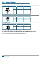
Nozzle Selection
Default = Red or 0.4 US GPM (1.29 l/min) {0.33 Imperial GPM}
While in the nozzle selection step, the display will remain the same as in the Target Application Rate step except the indicator arrow
flashing at the bottom of the display just above a color coded strip.
will be
NOTE: The tabbed color strip along the bottom of the display represents color coding for TeeJet® VisiFlo® spray tips. If you are using tips made
by another manufacturer, you should use the programmable tip capacity as explained in the System Setup section on page 14.
Select the representative color to match the spray tips being used to apply the desired application rate. Use the Plus key
or Minus key
to toggle the indicator arrow
through the tabbed color strip at the bottom of the display panel. The corresponding flow rate for each color will
be displayed in US Gallons Per Minute (Liters Per Minute) {Imperial Gallons Per Minute} at 40 psi (2 bar) at the lower right of the display. If the
programmable tip is to be used, toggle the indicator arrow
symbol to the “P” tab. Flow rate will always be displayed in US Gallons Per Minute
(Liters Per Minute) {Imperial Gallons Per Minute} at 40 psi (2 bar) regardless of any changes to other display parameters.
The table at the bottom indicates flow rates in US Gallons Per Minute (Liters per Minute) {Imperial Gallons Per Minute} at 40 psi (2 bar) for the
TeeJet® VisiFlo® color coded spray tips represented in the 844 Spray Control.
Warning: C
olor coding of spray tips is not uniform from manufacturer to manufacturer. Flow rates for all nozzles should be checked prior to use.
Tips that are worn should be replaced to ensure an accurate application rate.
Required Speed to Achieve the Application Rate
Based on the tip programmed and nozzle spacing (programmed in the System Setup Mode), the 844 console will calculate the required
speed to achieve the application rate that was entered in the last programming step. The speed will be displayed in the lower left corner of the
display window. Keep in mind that this speed is based on a spraying pressure of 40 psi (2 bar). More calculations can be performed in the next
programming step.
When the correct flow rate for the spray tips being used has been entered, press the Program key
step.
TeeJet® VisiFlo®
Tip Color
Flow Rate in
US GPM at 40 PSI
Flow Rate in
l/min at 2 bar
Flow Rate in Imperial
GPM at 40 PSI
Orange
0.10
0.32
0.08
Green
0.15
0.48
0.12
Yellow
0.20
0.64
0.17
Blue
0.30
0.97
0.25
Red
0.40
1.29
0.33
Brown
0.50
1.61
0.42
Gray
0.60
1.93
0.50
White
0.80
2.58
0.67
Light Blue
1.00
3.22
0.83
Light Green
1.50
4.83
1.25
Black
2.00
6.45
1.67
to accept the value and advance to the next
98-70006-ENUS R4
21
844-E Sprayer Control
Calculation Troubleshooting
This Programming Step is a diagnostic tool only
This programming step has no effect on the operation of the TeeJet
844 Sprayer Control. It allows the user to adjust the indicated pressure
to see what effects it would have on the operating speed; or the user
can adjust the speed to see what pressure would need to be used to
maintain the target application rate. This step should help determine if
the correct nozzle size was chosen for the application.
While in the calculation step, either the pressure “PSI” (bar) or speed
“MPH” (km/h) units will be flashing.
Adjust Speed:
While in the Calculation Step, the user is able to view the nozzle
flow rate, pressure, speed and application rate simultaneously.
When first entering this step, the speed “MPH” (km/h) units will be
flashing, indicating that this digit can be changed. By pressing the
Plus key
or Minus key , the programmer can change the
indicated speed to a desirable speed or typical operating speed.
The 844 will immediately calculate what the pressure would need to
be to maintain the target application rate at this speed. If the pressure
is too high, you will need larger spray tips or will have to slow down. If
the pressure is too low, you will need smaller spray tips or will have to
speed up.
Adjust Pressure:
If you wish to adjust the pressure, press the Program key
once so that the pressure “PSI” (Bar) units begin to flash. Use the
Plus key
or Minus key
to adjust the indicated pressure to
a desired or recommended pressure. The 844 will immediately
determine what the operating speed would need to be to achieve
the target application rate at this pressure. If the speed indicated
is too high, a smaller nozzle is needed. If the speed indicated is
too low, a larger nozzle is needed.
Liquid Density:
All calculations performed in the normal Calculation Step are based
on spraying water. To convert these calculations to the Liquid Density
programmed in the Liquid Specific Gravity (Density) Step in the System
Setup Mode (page 14), press the Auto/Manual key. When calculations
are using the programmed Specific Gravity (Density), the D symbol
will be displayed at the top of the display window. To go back to the
calculations based on spraying water, press the Auto/Manual key.
22
www.teejet.com
NOTE: If you are going to be spraying with a different density of liquid
other than water and you have programmed that specific
gravity (density) into the Specific Gravity (Density) Step in the
System Setup Mode, you must select the density symbol D at
the top of the display in order for all of the calculations to be
performed in the regular spraying mode. If when in the regular
spraying mode, you do not see the density symbol D at the
top of the display, this means that you have not selected a
different specific gravity of liquid and that all calculations will
be performed with water (1.00).To spray with a different density
liquid, the specific gravity must first be programmed into the
System Setup Mode in the Specific Gravity (density) step on
page 19. Once a number has been programmed into that step,
you must select the density symbol D in the Application Setup
Mode by pressing the Auto/Manual key.
NOTE: The tip flow rate, in the lower right corner of the display, will
always display the flow rate in US Gallons Per Minute (Liters
Per Minute) {Imperial Gallons Per Minute} at 40 psi (2 bar),
regardless of changes to the indicated pressure.
After performing the calculations, you can advance to the beginning
of the Application Setup sequence to make any changes by pressing
the Program key
once. If no changes are necessary, you have
completed the Application Setup Mode of the TeeJet 844 Sprayer
Control.
NOW, PRESS AND HOLD THE PROGRAM KEY
FOR THREE (3)
SECONDS, AND THE ENTIRE APPLICATION SETUP MODE WILL BE
STORED IN THE COMPUTER’S MEMORY.
NOTE: For your protection, the 844 console will not automatically
power down while in the Application Setup Mode. You must exit
properly as described above to enable the console auto power
down feature.
NOTE: Cutting the power to the controller while in the Application
Setup Mode will not save any changes made into the
computer’s memory.
844-E Sprayer Control
Chapter 4 - Operating Instructions
Sprayer Checkout
Before spraying, check all connections related to the Sprayer Control
assembly. Particular attention should be given to the speed sensor to
be sure the sensor and magnets are in line, and properly secured.
WARNING: W
henever you are working around a sprayer or farm
chemicals, be sure to wear protective clothing and eye
wear.
Partially fill the sprayer tank with water to flush the system and to make
a visual check of the spray tips to be sure all tips are delivering a good
spray pattern.
Follow these steps, in sequence, being sure the Master Boom Switch is
in its “off” position:
1. Be sure the tank shut-off valve is open.
2. Start the engine, engage pump, and set the rpm to that which will
be used when spraying.
3. Switch the computer on by pressing the Program key
on the
display panel.
4. Ensure that the spray tips being used match those pre
programmed.
5. Turn “on” the toggle switches for each of the spray booms on your
sprayer.
6. Press the Auto/Manual key so that the red LED light indicates
“MAN” mode.
7. Now, toggle the Master boom switch to “on.”
8. Adjust the pressure with the Plus key
and/or Minus key .
9. While spraying, adjust the pressure with the
key to the system’s
minimum point.
10.Now press the Plus key
for three (3) seconds. This will move
the regulating valve to its middle position.
11. Manually adjust the system pressure using a throttle valve in the
supply line or a manual shutoff valve on a bypass line. Adjust the
system pressure so that it is close to what your operating pressure
will be for your application.
12.This ensures a maximum range of automatic adjustment while
spraying in Auto mode.
At this point, the sprayer will be activated and spray tip performance
can be visually checked. The pressure adjust keys can be used to raise
or lower your spraying pressure. To stop spraying, toggle the Master
boom switch to “off”.
The Spraying Operation
You have filled the sprayer tank and have thoroughly mixed the
chemical(s).Your application rate has been determined as well as the
spray tip you will be using, with the sprayer data programmed into the
computer.
1. Switch the computer on by pressing the Program key
on the
display panel.
2. Toggle the boom switches to their “on” position, for each of the
booms on your sprayer.
3. Take note of the “numbered” booms on each side of the sprayer, so
that the appropriate boom can be toggled “off” as necessary.
4. The Auto/Manual key should be switched to “AUTO.”
5. In the Auto mode, when the master boom switch is “off”, the target
application rate as well as the target symbol
will be displayed
in the console display. When the master boom switch is “on”, the
will no
actual rate will be displayed and the target symbol
longer appear.
6. On flow based models, the lower right corner of the display will
alternate displays of the application area
(“Ac” for acres or “Ha” for hectares) and the total volume applied.
The display will alternate approximately every three seconds.
7. While spraying with the master boom switch “on”, the display
window will always display the actual application rate, vehicle
speed, pressure and application area covered/total volume applied
simultaneously.
As you enter the field to the point where you will begin spraying,
turn the MASTER boom switch to “on” position. This will activate the
spraying operation. Maintain your usual vehicle speed for spraying.
Moderate changes in vehicle speed will not affect your application
rate, because such changes are compensated by automatic pressure
increases or decreases.
If for any reason you need to stop, turn the MASTER boom switch to
“off.”
Alarm warnings can occur momentarily while the pressure regulating
valve is searching for a new setting after the closing of a boom section
or other change in normal operation. However, if the alarm stays on for
a longer time, the valve may have reached its limit and your system will
be unable to regulate flow beyond the limit.
The above steps provide a quick way to check out your sprayer and
computerized control system.
NOTE: It is recommended that you calibrate your sprayer to prepare
the unit for operation, and to diagnose spray tip wear. Worn
tips can contribute to costly chemical waste, and inaccurate
spraying regardless of your use of a sprayer control. Calibration
is important and necessary to obtain the benefits associated
with a computerized sprayer control.
98-70006-ENUS R4
23
844-E Sprayer Control
Chapter 5 - Features
Boost Mode
There may be instances where ”on the go” increased or decreased
chemical application may be required in certain areas of your field.
In situations like this, the Plus key
and Minus key
will allow
you to easily make the necessary adjustments. The boost mode can
be activated while spraying in the Auto mode by pressing either the
Plus key
or Minus key
once. With each subsequent press of
the Plus key , the application rate will be increased by 10%. Each
subsequent press of the Minus key
will reduce the application rate
by 10%.
If the Plus key
or Minus key
is pressed once inadvertently
during operation, a delay of three seconds will deactivate the boost
mode. Succeeding presses will change the target rate as explained
above.
Example: If increasing the application rate by 10%, press the
Plus key
once to activate the boost mode, and a
second time to make the 10% increase. If decreasing the
application rate by 10%, repeat the above procedure using
the Minus key
.
The application rate changes are monitored in the display, as you make
them. The display will show UP 10, UP 20, dn 20, dn 30,
etc. This will be displayed for approximately 3 seconds before the
display returns to reading actual application rates. When making the
application rate changes, it is not necessary to set the Auto/Man to
“MAN” mode.
To return the application rate to its programmed status, you may use
the Plus key
or Minus key
individually to step back to the
application rate in 10% increments, or press them simultaneously to
return to the programmed target application rate.
NOTE: While in the boost mode, the target symbol
will flash at the
top of the console display, to remind the operator they are not
spraying at the target application rate.
Area/Volume Feature
The 844 Sprayer Control will count application acres (hectares) and
measure total volume applied while the master boom switch is in the
“on” position. The area counter will measure treated acres (hectares)
and is dependent on the value programmed for nozzle spacing on page
15. The volume measure is dependent on flow meter pulses and is
available on flow based models only.
The lower right of the display window will alternately show the treated
area sprayed and the total volume applied since the last clearing of the
area counter/volume measure.
24
www.teejet.com
To clear the area counter/volume measure, press and hold the Plus
key
and Minus key
simultaneously for three (3) seconds while
viewing the normal operating mode.
NOTE: The area memory counter/volume measure only works when
the Master Boom Switch is turned “ON”.
NOTE: If you are using a pressure based controller, the Volume feature
is disabled. The total area will then be displayed at all times
Flow Rate Feature
The 844 Sprayer Control will measure a flow rate moving through
the flow meter in GPM (LPM) {Imp GPM}. This feature is activated by
pressing and holding the Program key
while spraying in the normal
operating mode. The flow rate display replaces the area/volume display
in the lower right portion of the display.
Any time the Program key
is pressed while spraying in the normal
operating mode the flow rate will be displayed. Releasing the Program
key
will cause the display to return to area/volume.
This feature can be used for tip calibration or for calibrating the flow
meter. Refer to page 29 of this manual for flow meter calibration
procedures.
NOTE: Not all 844 models contain this feature. If the display makes no
change when pressing on the Program key
while spraying
in the normal operating mode, then this feature is not available
with this console.
Application Alarm
If the 844 senses a continuous discrepancy of 10% or more between
the Target Application Rate and the Actual Application Rate, the
application rate units (GPA, G/1000 ft2 or l/ha) will flash in the display
window. This alarms the operator to a problem with the sprayer
plumbing, operation or programming.
No Flow Alarm
If the 844 stops receiving pulses from the flow meter, the turbine
will flash at the top of the display. This alarm indicates
symbol
that the flow meter has stalled and alerts the operator that there is a
problem with the flow meter or elsewhere in the system.
This alarm will occur only when the Master Boom Switch and at least
one boom toggle switch is “on”.
844-E Sprayer Control
Printing
Optional printers are available for printing a spraying report directly
from the 844. The optional printers are available through your TeeJet
supplier. The printout that you get from the 844 contains memory
information that the 844 collects. A sample of this printout is below.
To set the 844 for printing, advance to the last step of the System
Setup mode and select “Prt” for the communications mode. This must
only be done once.
Next, connect the printer to the 844 and make sure that the LED’s to
the printer are lit indicating that the printer has power. Simultaneously,
press and hold the Plus key
and Minus key
for three seconds
or until the printer begins printing. When the printer is finished, the area
and volume counters in the lower right of the display will be reset to
zero.
Disconnect the printer and continue spraying activity if necessary.
Warning: Each time you print, the area and volume counters are
reset to zero. If you do not have the printer connected
and have programmed the 844 for printing capability and
you are resetting the area and volume counters, the 844
console will be locked for a short period of time. The 844
is trying to print and is dumping the memory information to
the printer port. When the 844 has finished dumping the
information, the display will return to normal.
Figure 21: Spraying Report
98-70006-ENUS R4
25
844-E Sprayer Control
chapter 6 - Troubleshooting Guide
Condition
Possible Cause
Solution
1. A
pplication Rate Units (GPA, G/1000
ft2 I/Ha) continually flash on/off
A. C
ontinuous discrepancy of 10% or
more between Target Application
Rate and Actual Application Rate
Check all components and programming steps related to flow
Programming
B. Flow meter pulses
In the System Setup mode, move to the Flow Meter Pulses section on page 14 of the
844 Installation Manual. Enter the factory calibrated flow meter pulse rate located on
the tag accompanying the flow meter.
C. Nozzle Selection
In the Application Setup mode, move to the Nozzle Selection section on page 29 of
the 844 Installation Manual. Enter the correct color or the flow rate in US GPM (l/min)
{Imp. GPM} of the tips you are using at 40 psi (2 bar). For new tips, this can be found
in your TeeJet® Catalog.
If the tips have been used and possibly worn, measure the flow in US Gallons Per
Minute (Liters Per Minute) {Imperial Gallons Per Minute) at 40 psi (2 bar) and enter
the value in the User Programmable tip programming step which can be found in the
System Setup Mode on page 14 of the 844 Installation Manual.
2. Application Rate Units continually
flash on/off
D. Number of spray tips per boom
section
In the System Setup mode, move to the Tips Per Boom Section step on page 15 of
the 844 Installation Manual. You must enter the correct number of spray tips for each
boom section on your sprayer. Five boom sections are possible. If you do not use all
boom section switches, make sure those not used are set to “0”. Make sure that the
switch numbers being used correspond with the section numbers programmed.
A. Continuous discrepancy of 10% or
Check all components and programming steps related to flow
more between Target Application
Rate and Actual Application Rate
Mechanical
B. Stalled meter pulses
Make sure there is no pressure in the system. Remove the flow meter from the
discharge line. Inspect the inside of the meter for obstructions. The turbine should
move freely. If it does not rotate easily, try flushing it out with clean water. If it remains
stuck, remove the turbine by releasing the retaining clip. Clean the turbine carefully
and make sure it rotates. Replace the turbine into the flow meter body and secure with
the retaining clip.
If you have a rapid check flow meter, remove the turbine from the flow meter body by
unthreading it at the sensor. Check the turbine for obstructions. Flush with clean water
or disassemble if necessary.
C. Plugged tips
In the event of plugged nozzles, remove from boom and clean with water and a TeeJet
brush. Take care not to damage the orifice.
D. Wrong capacity tips
All tips on the boom should be of the same style, spray angle and capacity (Flow
Rate). Replace any tips not matching those initially selected.
E. F
low meter plumbed incorrectly
A flow directional arrow is located on the body of the flow meter. Plumb the flow meter
with the arrow in the direction of the flow.
The flow meter must be mounted 10″ to 12″ (25-35 cm) from other pipe fittings. See
844 Installation Manual page 7.
Generally, the flow meter works better when mounted in a vertical position with the
flow being directed up.
F. Pump capacity too low
Check the pump to make sure it is working correctly. Check the plumbing system for
any obstructions. Reduce Agitation Volume.
G. P
ump capacity too high
Some centrifugal pumps provide more flow than necessary for the application. A
throttle valve is sometimes required to restrict the flow coming from a centrifugal pump.
Increasing bypass and agitation volumes can also help when flows are too high to
reach the target application.
26
www.teejet.com
844-E Sprayer Control
Condition
3. Flow meter turbine symbol
Possible Cause
Solution
A. Stalled Flow meter
Make sure there is no pressure in the system.
continually flashes on/off
Remove the flow meter from the discharge line. Inspect the inside of the meter for
obstructions. The turbine should move freely. If it does not rotate easily, try flushing it
out with clean water. If it remains stuck, remove the turbine by releasing the retaining
clip. Clean the turbine carefully and make sure it rotates. Replace the turbine into the
flow meter body and secure with the retaining clip.
If you have a rapid check flow meter, remove the turbine from the flow meter body by
unthreading it at the sensor. Check the turbine for obstructions. Flush with clean water
or disassemble if necessary.
Check to ensure that the sprayer pump has been engaged while trying to spray.
Check cabling for any loose connections.
4. Rate oscillation
A. Extreme low regulated flow
Due to very low application rates (GPA, G/1000 ft2), (l/Ha) the regulating valve in
throttling mode is operating in an almost closed position.
Adjust the Reg. Valve Speed Number in the System Setup Mode (page 17) to a slower
value.
Plumb the regulating valve in bypass mode. This should allow the regulating valve to
operate more in the center of its rotation. If you change from throttling mode to bypass
mode, you must reprogram the Pressure Regulating Mode in the System Setup mode.
Refer to page 16 of the 844 Installation Manual.
5. Sprayer stops spraying while in Auto
Mode.
A. Pressure Regulating Mode is
programmed incorrectly
B. Flow meter stalled
Check the Pressure Regulating Mode in the System Setup mode of the 844. Refer to
page 16 of the 844 Installation manual to insure that the controller has been correctly
programmed for the regulating valve position on your sprayer.
A flashing turbine symbol
will also indicate if the flow meter has stalled. Inspect
flow meter for obstructions. If flow meter turbine is impaired, clean and replace.
Sometimes when the regulating valve closes too far, maybe even complete shut-off
(with ball type regulating valves), this can cause the flow meter to stall and no flow or
pressure regulation will occur. Press the Auto/Manual key so that the LED indicates
“MAN” mode, depress the Plus key
for approximately three (3) seconds. You
should see the tips begin to spray. Press the Auto/Manual key so that the LED
indicates “Auto” mode, and continue to spray.
98-70006-ENUS R4
27
844-E Sprayer Control
Condition
Possible Cause
Solution
6. A
pplication Rate Units (GPA, G/1000
ft2 I/Ha) continually flash on/off
A. S
peed sensor not calibrated
correctly
Recalibrate the magnetic or radar speed pulses in the Calibrate Speed section of the
System Setup Mode on page 18 of the 844 Installation Manual
B. Incorrect nozzle spacing
Check the Nozzle Spacing section in the System Setup Mode on page 15 of the
844 Installation Manual to ensure the correct nozzle spacing has been entered. This
number should reflect the distance between nozzles in inches or (cm) on the boom.
If banding, enter the band width as your spacing.
If directed spraying enter the row spacing divided by the number of nozzles per row
C. Incorrect capacity nozzles
The Nozzle Selection section in the Application Setup Mode on page 21 of the 844
Installation Manual does not match closely enough to the tips on the boom. Compare
the value in this section with the flow rate of the nozzles being used at 40 psi (2 bar).
D. Flow meter pulses incorrect
In the System Setup mode, move to the Flow meter Pulses section on page 14 of the
844 Installation manual. Enter the factory flow meter pulse rate located on the tag
accompanying the flow meter.
It might be necessary to recalibrate the flow meter. Follow the flow meter calibration
procedure(s) on pages 30-32 of this manual.
E. Speed sensor installed incorrectly
One or more of the wheel sensor magnets are not consistently sending a pulse to the
monitor.
The distance between the sensor and the magnets is incorrect. Ground debris can
accidentally move the sensor out of position. The red LED on the back side of the
sensor should be lit when placed within the correct distance form the magnets.
A proximity sensor has an orange LED on the top of the sensor that should be lit when
placed within the correct distance from the sensing surface.
7. No regulation in Auto Mode
F. Radar installed incorrectly
Precise installation of the Radar is critical to it working correctly. Thoroughly review the
manual provided with the Radar sensor you are using.
A. No speed sensing
Check speed sensor to ensure it is sending pulses to the controller. Check the
Calibrate Speed section in the System Setup Mode on page 18 of the 844 Installation
Manual to ensure speed sensors are correctly calibrated.
B. Regulating valve malfunction
Check wiring from controller to the regulating valve. Make sure there is voltage to the
regulating valve.
Both wires leading to the regulating valve are 12V(+). With the Master Switch on,
and the console set to MAN Mode when either the Plus key
or Minus key
is
pushed, the appropriate wire goes to ground (–) to complete the circuit.
28
www.teejet.com
844-E Sprayer Control
Chapter 7 - Flow meter Calibration
The flow meter supplied with your system has been calibrated at the factory and under normal circumstances there may be no need to re-calibrate
it. However, the factory calibration setup may not reflect specific sprayer plumbing. Before spraying actual chemicals, the flow meter should be
checked for proper calibration. Also, the flow meter is made up of moving parts and can wear over time. If you feel that your flow meter is worn,
you can re-calibrate your flow meter using the 844 console. To do so, use either of the following methods:
Method 1 – Known Volume
Step 1 – Known Value
Select a known volume of water (n) that you will pump through the flow meter. In these steps, 10 US gallons (38 liters) {8 Imperial gallons} will be
used as an example. The specific volume you use is not important, although larger volumes generally produce more accurate results.
Step 2 – Programming Calibration Number
Go into the System Setup mode and advance to the flow meter calibration number step (flashing turbine at the top of the display). In this
programming step, enter (n) 10 US gallons (38 liters) {8 Imperial gallons} as the calibration number. Exit the System Setup mode by pressing and
holding the key for five seconds.
Step 3 – Resetting Volume Counter
Reset the total volume number that is displayed in the lower right portion of the display. (Display alternates between Ac (Ha) covered and the
volume sprayed through the flow meter). To reset this number, press and hold the Plus key
and Minus key
simultaneously for three (3)
seconds or until you see the values reset to zero.
Step 4 – Spraying Known Volume
Engage the pump on the sprayer, flip the Master boom section of the 844 to “ON” (make sure at least one boom section switch is on), and pump
exactly (n) 10 US gallons (38 liters) {8 Imperial gallons} through the flow meter. When the known volume is reached, shut the Master boom switch
“OFF”.
Step 5 – Entering in New Flow meter Calibration Number
The number that is displayed in the lower right corner of the display is your new flow meter calibration number. Record this number, enter the
System Setup mode and advance to the flow meter calibration number step. Enter the new value from your test into this step and then exit the
System Setup mode.
Step 6 – Double-checking the New Value
Double-check your new value by spraying a larger volume of water, such as 100 US gallons (378 liters){83 Imperial gallons} through the flow
meter. Before spraying the larger volume, make sure to reset the memory counters by depressing and holding the Plus key
and Minus key
simultaneously for three (3) seconds.
NOTE: A
fter double checking the new calibration number, if you find that the volume shown on the display of the 844 is more than +/- 3% in error,
change the flow meter calibration number in the System Setup mode by the % difference it is in error.
Method 2 – Known Tip Size Method
Step 1 – Check Tip Size
Determine what size tip is on the sprayer. An actual flow collection should be done on a representative sample to ensure the tips are not worn. To
do this, set the boom pressure at 40 psi (2 bar). This must be pressure at the tips (i.e. use manual pressure gauge mounted on the boom). Collect
flow for 1 minute from 1 tip.
Example: XR8004 tip should spray 0.4 gallons in 1 minute (1.29 LPM) {0.32 Imp Gal}
Step 2 – Count Tips
Count the total number of tips to be used for measure. You can use 1 boom section, 2 boom sections, etc.
Example: Boom Section 1 has 10 tips
Step 3 – Calculated Flow
Multiply the number of tips to be measured by the size (or individual flow rate) of each tip.
Example: 10 tips x 0.4 GPM (1.29 LPM) {0.32 Imp GPM} = 4GPM (12.9 LPM) {3.2 Imp GPM}
98-70006-ENUS R4
29
844-E Sprayer Control
Step 4 – Measure
Turn controller on and activate pump. Toggle on the Master Boom Switch and the number of boom sections to be measured. Insure that the
pressure at the boom is maintained at 40 psi (2 bar). While spraying press and hold the Program key
in. Look at the lower right display to see
if the measured flow matches the calculated flow.
Step 5 – Adjustments
If the measured flow does not match the calculated flow, the flow meter number may need to be adjusted. If the measured flow is higher than the
calculated flow, the flow meter calibration number needs to be decreased. If the measured flow is lower than the calculated flow, the flow meter
calibration number needs to be increased.
Example: C
alculated flow is 4.00 GPM (12.9 LPM)
{3.20 Imp GPM}; measured flow is 3.6 GPM
(11.6 LPM) {2.88 Imp GPM}
Decrease the flow meter calibration number by 10%. If original number was 650, enter 585 for this programming value.
30
www.teejet.com
844-E
sprayer
control
U s e r
M a n u a l
• Full-featured sprayer control with industry-leading ease of use
• Large back-lit display shows all spraying information at a glance
• Color-coded tip selection for easy programming
• Communication Port for PC and GPS interfacing
• Flow or pressure based regulation options provide reliability and flexibility
• Five boom section switches plus master shutoff
• Built in application planning tool
• Durable, weather-resistant aluminum housing
• Single cable connection for quick hookup
1801 Business Park Drive
Springfield, Illinois 62703 USA
www.teejet.com
98-70006-ENUS R4 English-US
© TeeJet Technologies 2013