1
SCS 440
INSTALLATION
AND
SERVICE MANUAL
N O T I C E
The use of the suspension type fertilizers and lime slurries
will significantly reduce the life of the plastic parts in
the Flow Meter and motorized Control Valve. Check the rotor
and inlet hub assembly in the Flow Meter frequently for worn
parts. Excessive wear can affect accuracy.
Do not attempt to modify or lengthen any of the three-wire
Speed Sensor or Flow Meter cables. Extension cables are
available from your Dealer.
W A R N I N G
Disconnect console before jump starting, charging battery,
or welding on equipment.
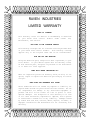
RAVEN INDUSTRIES
LIMITED WARRANTY
WHAT IS COVERED?
This warranty covers all defects in workmanship or materials
in your Raven Flow Control Product under normal use,
maintenance, and service.
HOW LONG IS THE COVERAGE PERIOD?
This warranty coverage runs for 12 months from the purchase date
of your Raven Flow Control Product. This warranty coverage
applies only to the original owner and is not transferrable.
HOW CAN YOU GET SERVICE?
Bring the defective part, and proof of date of purchase, to your
local dealer. If your dealer agrees with the warranty claim,
he will send the part, and proof of purchase to his distributor
or to Raven for final approval.
WHAT WILL RAVEN INDUSTRIES DO?
When our inspection proves the warranty claim, we will, at our
option, repair or replace the defective part and pay for return
freight.
WHAT DOES THIS WARRANTY NOT COVER?
Raven Industries will not assume any expense or liability for
repairs made outside our plant without written consent. We are
not responsible for damage to any associated equipment or
product and will not be liable for loss of profit or other
special damages. The obligation of this warranty is in lieu
of all other warranties, expressed or implied, and no person
is authorized to assume for us any liability. Damages caused
by normal wear and tear, mis-use, abuse, neglect, accident, or
improper installation and maintenance are not covered by this
warranty.
Manual Rev. R, SCS 440,
09/00
#016-0159-409
016-0159-409
9/00
TABLE OF CONTENTS
SYMBOL DEFINITION ............................................................................................................................................. 2
INTRODUCTION ...................................................................................................................................................... 3
INSTALLATION ......................................................................................................................................................... 4
1.
2.
3.
4.
MOUNTING
MOUNTING
MOUNTING
MOUNTING
THE
THE
THE
THE
RAVEN RADAR SPEED SENSOR ............................ 4
FLOW METER ........................................... 5
CONTROL VALVE ........................................ 5
CONSOLE AND CABLING .................................. 6
BATTERY CONNECTIONS ..................................................................................................................................... 7
CONSOLE FEATURES ............................................................................................................................................ 8
CONSOLE CALIBRATION ....................................................................................................................................... 9
1.
2.
3.
4.
5.
CALCULATING
CALCULATING
CALCULATING
CALCULATING
CALCULATING
"BOOM CAL" ............................................ 9
"SPEED CAL" .......................................... 10
"METER CAL" .......................................... 10
"VALVE CAL" .......................................... 11
"RATE 1 AND RATE 2 CAL" ............................. 12
CONSOLE PROGRAMMING ................................................................................................................................. 13
1. INITIAL CONSOLE PROGRAMMING ...................................... 14
2. OTHER DISPLAY FEATURES ........................................... 17
3. SELF TEST FEATURE ................................................ 17
4. VOLUME/MINUTE RATE FAULT ......................................... 18
5. VOLUME/AREA RATE ALARM ........................................... 18
6. LOW TANK FAULT ................................................... 18
7. AUTOMATIC RATE +/- ............................................... 18
8. CONTROL VALVE DELAY .............................................. 19
9. SEQUENCE TO ACTIVATE DATA-LOCK ................................... 19
10. SEQUENCE TO CHANGE DATA-LOCK .................................... 19
11. ENTER MODE SEQUENCE WITH ACTIVATED DATA-LOCK ................... 19
12. DATA MENU ....................................................... 20
13. DECIMAL SHIFT ................................................... 25
INITIAL SYSTEM SET-UP...................................................................................................................................... 26
INITIAL SYSTEM FIELD TEST .............................................................................................................................. 27
PREVENTIVE MAINTENANCE ............................................................................................................................. 27
TROUBLESHOOTING GUIDE............................................................................................................................... 28
APPENDIXES
1. WHEEL DRIVE SPEED SENSOR INSTALLATION AND CALIBRATION ...................................................... 31
2. SPEEDOMETER DRIVE SPEED SENSOR INSTALLATION AND CALIBRATION ....................................... 34
3. ALTERNATE BY-PASS LINE PLUMBING SYSTEM........................................................................................ 36
4. PROCEDURE TO TEST SPEED SENSOR EXTENSION CABLES ............................................................... 38
5. PROCEDURE TO TEST FLOW METER CABLES .......................................................................................... 39
6. FLOW METER MAINTENANCE AND ADJUSTMENT PROCEDURE ........................................................... 40
7. PROCEDURE TO RE-CALIBRATE FLOW METER ........................................................................................ 41
8. REMOTE SWITCH OPTION .............................................................................................................................. 42
9. SERIAL INTERFACE.......................................................................................................................................... 43
10. SCS 440 COMMUNICATION STRINGS ......................................................................................................... 44
REPLACEMENT PARTS SHEETS
1
SYMBOL DEFINITION
GPM
lit/min
dl/min
PSI
kPa
GPA
lit/ha
ml/ha
GPK
mm
-
cm
dm
m
MPH
km
km/h
US
SI
TU
[]
{}
Gallons per minute
Liters per minute
Deciliter per minute
Pounds per square inch
Kilopascal
Gallon per acre
Liter per hectare
Milliliter per hectare
Gallons per 1,000 sq. ft.
Millimeters
-
Centimeters
Decimeters
Meter
Miles per hour
Kilometers
Kilometers per hour
Volume per acre
Volume per hectare
Volume per 1,000 sq. ft.
Metric numbers
1,000 sq. ft. numbers
METER CAL CONVERSIONS
To convert the METER CAL number simply divide the original number (number printed
on Flow Meter label) by the desired conversion factor.
FOR EXAMPLE:
Original METER CAL No. = METER CAL No. for displays in Fluid Ounces
128
Original METER CAL No. = METER CAL No. for displays in Liters
3.785
Original METER CAL No. = METER CAL No. for displays in Pounds
Weight of one gallon
LIQUID CONVERSIONS
U.S. Gallons x 128 = Fluid Ounces
U.S. Gallons x 3.785 = Liters
U.S. Gallons x 0.83267 = Imperial Gallons
U.S. Gallons x 8.34 = Pounds (Water)
LENGTH
1 millimeter (mm) = 0.039 inch
1 centimeter (cm) = 0.393 inch
1 meter (m) = 3.281 feet
1 kilometer (km) = 0.621 mile
1 inch = 25.4 millimeters; 2.54 centimeters
1 mile = 1.609 kilometers
PRESSURE
1 psi = 6.89 kPa
1 kPa = 0.145 psi
AREA
1 square meter = 10.764 square feet
1 hectare (ha) = 2.471 acres; 10,000 square meters
1 acre = 0.405 hectare; 43,560 square feet
1 square mile = 640 acres; 258.9 hectares
2
INTRODUCTION
The Raven SCS 440 (SPRAYER CONTROL SYSTEM) is designed to improve the uniformity of spray
applications. Its performance relies on the installation and preventive maintenance
of the complete sprayer. It is important that this Installation and Service Manual be
reviewed thoroughly before operating the system. This manual provides a simple stepby-step procedure for installing and operating.
The SCS 440 system consists of a computer-based control Console, a Speed Sensor, a turbine
type Flow Meter and a motorized Control Valve. The Console mounts directly in the cab
of the vehicle for easy operator use. The Radar Speed Sensor is mounted to the frame
of the vehicle or implement (Wheel Drive and Speedometer Drive Speed Sensors are also
available). The motorized Control Valve and Flow Meter mount to the framework supporting
the boom. Appropriate cabling is furnished for field installation.
The operator sets the target volume per area to be sprayed and the SCS 440 automatically
maintains the flow regardless of vehicle speed or gear selection. A manual override
switch allows the operator to manually control flow for system check-out and spot
spraying. Actual volume per area being applied is displayed at all times. The SCS 440
additionally functions as an area monitor, speed monitor, and volume totalizer.
3
INSTALLATION
1.
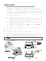
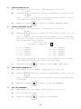
MOUNTING THE RAVEN RADAR SPEED SENSOR
See Appendix 1 for Wheel Drive Speed Sensor installation instructions.
See Appendix 2 for Speedometer Drive Speed Sensor installation instructions.
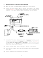
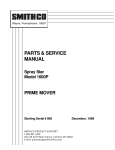
For mounting the radar, the following guidelines will assure proper installation:
It is suggested that a large heavy mounting bracket, (P/N 107-0159-693) be attached
to the vehicle frame for mounting the radar.
1)
Park vehicle on level surface.
2)
Select mounting site by considering the following:
a)
The line of sight from the lens to the ground must not be obstructed by
structures or tires. Obstructions must not come closer than 20 inches to
the bottom of the radar. See Figures 1 and 2.
b)
The radar lens must be parallel to the ground from front to back. Radar
can be tilted out 0-15 degrees to provide more clearance and miss
obstructions. See Figure 2.
c)
The radar should be mounted so that the length of the radar is parallel with
direction of vehicle travel.
3)
Use carpenters level to verify that mounting bracket is parallel to the ground.
4)
Bolt mounting bracket to implement.
5)
Bolt radar to mounting bracket using mounting hardware.
6)
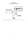
Connect radar with Radar Interface Cable (P/N 115-0159-539), to the Console. The
Red wire should be connected to the Orange cable wire. The White wire should be
connected to the White cable wire (See "BATTERY CONNECTIONS").
CAUTION:
See Figure 3.
The connection of the radar power in reverse polarity could result
in damage to the radar.
FIGURE 2
FIGURE 1
4
FIGURE 3
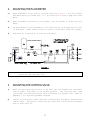
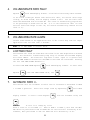
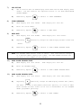
2.
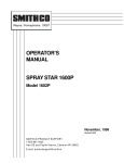
MOUNTING THE FLOW METER
1)
Mount Flow Meter in the area of the boom valves per Figure 4. All flow through
Flow Meter must go to booms only, i.e., no return line to tank or pump after Flow
Meter.
2)
Mount Flow Meter horizontal to the ground.
Meter.
3)
For best results, allow a minimum of 7 1/2 inches [20 cm] of straight hose on inlet
of Flow Meter. Bend radius of hose on outlet of Flow Meter should be gradual.
4)
Flow must be in direction of arrow on Flow Meter.
Use the bracket to secure the Flow
FIGURE 4
NOTE: It is essential, when using suspensions, that the system be thoroughly
rinsed out each day after use.
3.
MOUNTING THE CONTROL VALVE
1)
Mount the motorized Control Valve in the main hose line between the Flow Meter
and the booms, with motor in the upright position. (For flow less than 3 GPM
[11 lit/min] the motorized Control Valve is mounted in a by-pass line. Refer to
Appendix 3 for alternate plumbing diagram).
2)
Connect the Flow Control Cable connectors to boom valves, Flow Meter, and motorized
Control Valve. (Black wire to boom valve #1, Brown wire to boom valve #2 and Blue
wire to boom valve #3.
5
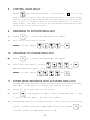
4.
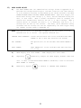
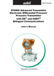
MOUNTING THE CONSOLE AND CABLING
1)
Mount the Console to a secure support inside the cab of the vehicle.
2)
Connect the Console Control Cable to the plug in the back of the Console.
(Reference Figure 5). Route the Console Control Cable out of the vehicle cab and
terminate. (Flow Meter extension cables are available from your Dealer).
FIGURE 5
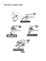
3)
Turn POWER ON/OFF switch OFF and route the Red and White battery wires to a 12volt battery. Attach the White battery wire to the NEGATIVE (-) terminal and the
Red battery wire directly to the POSITIVE (+) battery terminal. (See Figure 6).
(DO NOT CONNECT RED AND WHITE WIRES TO THE STARTER). Secure the battery wires
with plastic cable ties. DO NOT tie the battery wires close to the existing battery
leads or any other electrical wiring.
4)
Connect the Speed Sensor Cable to the plug in the back of the Console.
5)
Secure and tie the Speed Sensor Cable and the Console Control Cable with plastic
cable ties.
6)
Initial installation of the system is now complete.
6
BATTERY CONNECTIONS
FIGURE 6
7
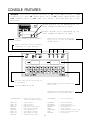
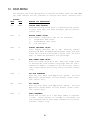
CONSOLE FEATURES
IMPORTANT: This Console requires selection of US (acres), SI [hectares], or TU
{1,000 sq. ft.} area; SP1 (wheel drive, etc.) or SP2 (radar) speed sensor; and
C-Sd (Standard Valve) or C-FC (Fast Close Valve). Hold SELF TEST key to view
selections.
Console Revision can be determined by the
letter stamped in REV box on label.
Console Program can be determined by the
letter stamped in PGM box on label.
Booms can be controlled individually, or all at once with MASTER
ON/OFF switch.
Selects manual or fully automatic
control.
Manual override control provides
capability for spot spraying.
CE -Use like you do the CE key on
a calculator.
ENTER -Used only to enter data into
the Console.
Selects POWER ON or OFF.
Displays actual rate of application,
calibration, and function data.
CALIBRATION KEYS --
Used to enter data into the
Console to calibrate the system.
FUNCTION KEYS
--
Used to Display Data
BOOM 1 CAL
BOOM 2 CAL
BOOM 3 CAL
SPEED CAL
METER CAL
VALVE CAL
RATE 1 CAL
RATE 2 CAL
SELF TEST
Length of Boom 1
Length of Boom 2
Length of Boom 3
Determined by Speed Sensor
Meter Calibration Number
Valve Response Time
Target Application Rate
Target Application Rate
Simulates Vehicle Speed
TOTAL AREA
FIELD AREA
FIELD VOLUME
DISTANCE
SPEED
VOLUME/TANK
TIME
DATA MENU
---------
Total Area Applied
Field Area Applied
Volume Applied to Field
Distance Traveled
Speed of Vehicle
Volume Remaining in Carrier Tank
24 Hour Clock (Military Time)
Printer Option
----------
8
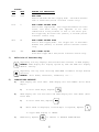
CONSOLE CALIBRATION
1.
CALCULATING "BOOM CAL"
1)
Broadcast Spraying
Calculate the width of each boom in inches [cm] by multiplying the number of tips
times the spacing.
Write these boom widths down for future reference when
programming the Console.
FIGURE 7
2)
Band Spraying
Calculate the width of each boom in inches [cm] by multiplying the number of tips
by the spacing. Calculate the Adjusted Applied Rate by multiplying the Broadcast
Rate by Band Width in inches [cm] divided by Spacing in inches [cm].
EXAMPLE:
Broadcast Rate
Spacing
Band Width
Adjusted Applied Rate
= 20 GPA [200 lit/ha]
= 40 inches [100 cm]
= 14 inches [40 cm]
= GPA x Band Width
Spacing
= 20 x 14 = 7 GPA
40
= [200] x [40] = [80 lit/ha]
[100]
9
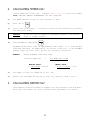
2.
CALCULATING "SPEED CAL"
Initial SPEED CAL is 598 [152]. Complete Steps 1 thru 6 to refine this number
after "INITIAL CONSOLE PROGRAMMING" has been completed.
1)
Set POWER switches to ON, all other switches to OFF.
2)
Enter "0" in
3)
Drive 1 mile [1 kilometer]. To achieve the most accurate calibration, accelerate
and decelerate slowly.
CAUTION:
4)
Do not use vehicle odometer to determine distance.
lines or highway markers.
Read DISTANCE by depressing
Use section
.
DISTANCE should read a value of approximately 5280 [1000]. If it reads between
5260-5300 [990-1010], the SPEED CAL for the vehicle is 598 [152]. If the DISTANCE
display reads any other value, perform the following calculation:
EXAMPLE:
Assume DISTANCE reads 5000 [980].
Corrected SPEED CAL
=
Old SPEED CAL x 5280
DISTANCE
ENGLISH UNITS:
= 598 x 5280 = 631.48
5000
METRIC UNITS:
= [152] x [1000] = [155]
[980]
5)
The number to enter for SPEED CAL is 631 [155].
6)
Recheck the new SPEED CAL derived in Step 5 by repeating Steps 2 thru 5.
3.
CALCULATING "METER CAL"
The Flow Meter calibration number is stamped on the tag attached to each Flow Meter.
Write down this number for future reference when programming the Console.
10
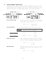
4.
CALCULATING "VALVE CAL"
The initial Control Valve calibration number for VALVE CAL is 2123 for C-Sd
(standard valve) or 743 C-FC (fast close valve). The VALVE CAL number is used to
control response time of the Motor Control to the change in vehicle speed. After
operating the system, this number maybe refined. See definitions below:
For STANDARD VALVE (C-Sd):
Valve Backlash Digit
For FAST VALVE (C-FC):
Controls the time of the first correction pulse
after a change in correction direction is detected.
(INC to DEC -or- DEC to INC).
Range: 1 to 9
Valve Speed Digit
1-Short Pulse
9-Long Pulse
Controls response time of Control Valve motor.
CAUTION:
Running the Control Valve too fast will
cause the system to oscillate.
C-Sd Valve Control
Range:
1 to 9
1-Slow
9-Fast
C-FC Valve Control
Range:
0 to 9
0-Fast
9-Slow
Brake Point Digit
Sets the percent away from target rate at which the
Control Valve motor begins turning at a slower
rate, so as not to overshoot the desired rate.
Range: 0 to 9
Dead-Band Digit
0 = 5%
1 = 10%
9 = 90%
Allowable difference between target and actual
application rate, where rate correction is not
performed.
Range: 1 to 9
11
1 = 1%
9 = 9%
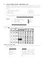
5.
CALCULATING "RATE 1 AND RATE 2 CAL"
Determine the application rate at which chemical is to be sprayed. Consult with
a Dealer to ensure these spray nozzles are capable of applying at this rate. In
determining which spray nozzles to use with the sprayer the following must be
known:
1)
2)
3)
4)
Nominal Application Pressure
Target Application Rate
Target Speed
Nozzle Spacing
___
___
___
___
PSI [kpa]
GPA [lit/ha]
MPH [km/h]
inches [cm]
From this information, calculate the volume per minute, per nozzle as follows:
GPM [lit/min] = GPA [lit/ha] x MPH [km/h] x inches [cm]
5,940 [60,000]
EXAMPLE:
1)
2)
3)
4)
Application Pressure
Target Application Rate
Target Speed
Nozzle Spacing
GPM = 20 GPA x 5.2 MPH x 20 inches
5,940
=
=
=
=
30 PSI
20 GPA
5.2 MPH
20 inches
= .35
Using GPM .35 and pressure 30 select tip number XR8004 from the chart below, since it
comes closest to providing the desired output.
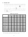
VERIFYING FLOW RATE LIMITS:
The flow rate of spraying must be within the range of that specified for the Flow
Meter included.
FLOW METER MODEL
RFM 5
RFM 15
RFM 55/55A
RFM 100
RFM 200/200 Poly
RFM 400
FLOW RANGE
0.05-5 GPM [0.2-18.9 lit/min]
0.3-15 GPM [1.1-56.8 lit/min]
1-55 GPM [3.8-208 lit/min]
3-100 GPM [11.4-379 lit/min]
15-200 GPM [56.8-757 lit/min]
25-400 GPM [94.6-1514 lit/min]
12
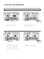
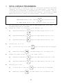
CONSOLE PROGRAMMING
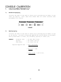
When entering data into the Console, the entry sequence is always the same.
NOTE: DATA MUST BE ENTERED INTO KEYS 1 THRU 8.
Depress the key in which
you wish to enter data.
Depress the ENTER key. An
"E" will illuminate in the
DATA display.
Depress the keys corresponding to the number you wish to
enter (i.e. "7","4","3").
The numbers will be displayed as they are entered.
Complete the entry by again
depressing the ENTER key.
13
1.
INITIAL CONSOLE PROGRAMMING
When Console power is turned on, after all installation procedures have been
completed, the Console will flash "CAL" in the RATE display. This means the
console must be "calibrated", or programed, before it can be operated. This is
a one-time operation which does not have to be repeated. Turning OFF the POWER
ON/OFF switch does not affect the Console memory. All data is retained.
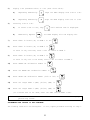
IMPORTANT:
If an entry selection error is made during Steps 1-6, place the
POWER ON/OFF switch to OFF. Depress
the POWER ON/OFF switch to ON.
1)
2)
3)
4)
and hold while placing
This will "reset" the Console.
The DATA display will show "US", and the RATE display will show "CAL".
following Steps must be followed:
Display US (acres), SI [hectares], or TU {1000 sq. ft.}.
a)
Depressing momentarily
steps the DATA display from US to SI.
b)
Depressing momentarily
steps the DATA display from SI to TU.
c)
Depressing momentarily
steps the DATA display from TU to US.
The
Selecting US, SI, or TU.
a)
To select US, SI, or TU, step
b)
Momentarily depress
until the desired code is displayed.
, the DATA display will now display SP1.
Display SP1 (wheel drives, etc.) or SP2 (radar sensor).
a)
Depressing momentarily
steps the DATA display from SP1 to SP2.
b)
Depressing momentarily
steps the DATA display from SP2 to SP1.
Selecting SP1 or SP2.
a)
To select SP1 or SP2, step
b)
Momentarily depress
until desired code is displayed.
, the DATA display will now display C-Sd.
14
5)
6)
Display C-Sd (Standard Valve) or C-FC (Fast Close Valve).
a)
Depressing momentarily
steps the DATA display from C-Sd to C-FC.
b)
Depressing momentarily
steps the DATA display from C-FC to C-Sd.
Selecting C-Sd or C-FC.
a)
To select C-Sd or C-FC, step
b)
Momentarily depress
until desired code is displayed.
, the DATA display will now display "0".
7)
Enter width in inches [cm] of BOOM 1 in the
8)
Enter width in inches [cm] of BOOM 2 in
.
.
If there is only one boom, enter a "0" for width of BOOM 2.
9)
.
Enter width in inches [cm] of BOOM 3 in
If there is only one or two booms, enter a "0" for width of BOOM 3.
.
10)
Enter SPEED CAL calibration number in
11)
Enter the METER CAL calibration number in
12)
Enter VALVE CAL calibration number (2123 or 743) in
13)
Enter the target RATE 1 (GPA) [lit/ha] {GPK} in
.
14)
Enter the target RATE 2 (GPA) [lit/ha] {GPK} in
.
.
.
(If a second rate is not used, enter the same rate as RATE 1 CAL).
NOTE: RATE 2 should not be more than 20% different from RATE 1 or else spray
pattern may suffer.
PROGRAMMING THE CONSOLE IS NOW COMPLETED.
The flashing "CAL" will now extinguish.
If not, repeat procedure starting at Step 7.
15
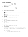
ENTERING ADDITIONAL DATA:
Data may be entered in the
and
although it is not required for the
operation of the system.
1)
ENTERING VOLUME:
Enter the estimated VOLUME in the TANK in
. Each time the tank is refilled,
this number must be re-entered.
2)
ENTERING TIME, DATE, AND POWER DOWN:
Definition of Time, Date, and Power Down Key:
Depressing this key displays selected Time features in DATA display.
EXAMPLE:
RATE display will display "TInE" and DATA will display 0:00.
Depressing this key again after selecting TIME increments through desired
features.
EXAMPLE: TIME, MONTH, DAY, YEAR, and POWER DOWN.
3)
Enter TIME
a)
b)
4)
Enter MONTH
a)
b)
5)
Select DAY
Enter DAY when RATE display shows "dAY"
Enter YEAR
a)
b)
7)
Select MONTH
Enter MONTH when RATE display shows "OnTH".
Enter DAY
a)
b)
6)
Select TIME
Enter TIME when RATE display shows "TInE".
Select YEAR
Enter YEAR when RATE display shows "YEAr"
POWER DOWN FEATURE
If the Console is not used for 10 days, it will go into a power down (low power)
mode of operation. In this mode, all data will be retained, but the time of day
clock will reset to 0:00. The delay time is initially set at 10 days, but can
be changed by the user.
a)
Enter POWER DOWN
1)
Select POWER DOWN
2)
Enter POWER DOWN when RATE display shows "Pdn".
16
2.
OTHER DISPLAY FEATURES
1)
To display TOTAL AREA covered, momentarily depress
.
To "zero out" this total at any time, enter a "0" in this key.
2)
To display TOTAL VOLUME sprayed, momentarily depress
To "zero out" this total at any time, enter a "0" in this key.
3)
To display FIELD AREA covered, momentarily depress
To "zero out" this total at any time, enter a "0" in this key.
4)
To display FIELD VOLUME sprayed, momentarily depress
To "zero out" this total at any time, enter a "0" in this key.
5)
To display DISTANCE (feet) [meters] traveled, momentarily depress
.
To
"zero out" this total at any time, enter a "0" in this key.
6)
To display SPEED, momentarily depress
7)
To display VOL/MIN, momentarily depress
8)
To display AREA/HOUR, momentarily depress
.
.
.
This is an actual calculation
of AREA/HOUR at the present speed you are going. It is not an average over a period
of time.
9)
To display US, SI, or TU; SP1 or SP2; and C-Sd or C-FC after being selected, depress
.
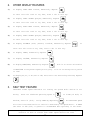
3.
SELF TEST FEATURE
SELF-TEST allows speed simulation for testing the system while vehicle is not
moving.
Enter the simulated operating speed in
desired, enter 6.0 [10.0]. Verify SPEED by depressing
.
If 6 MPH [10 km/h] is
. The SELF-TEST speed
will clear itself when motion of vehicle is detected by the Speed Sensor. A SPEED
CAL value of 900 [230] or greater is recommended when operating in this mode.
NOTE: To prevent nuisance clearing of self-test speed, disconnect speed
connector on back of Console when Radar Speed Sensors are used.
17
4.
VOLUME/MINUTE RATE FAULT
Depress
until DATA display flashes. A low limit flow rate may now be entered.
If the actual volume per minute falls below this limit, the Control Valve stops
closing, an alarm sounds, and the display flashes "-LL-". The low limit value
should be determined with all booms ON. This value is automatically proportional
to the percentage of booms that are ON. (i.e. If the entered low limit is 4 and
half the total boom length is shut off, the Console automatically reduces the low
limit to 2).
NOTE: Go to DATA MENU to silence alarm.
5.
VOLUME/AREA RATE ALARM
Console alarm sounds if the application rate is 30% or more away from the target
application rate for more than 5 seconds.
NOTE: Go to DATA MENU to silence alarm.
6.
LOW TANK FAULT
This feature will sound the alarm when the volume in the tank drops below an entered
value. The alarm will intermittently beep every 15 seconds and the RATE display
will flash "LEVL". The alarm will stop when a value equal to or greater than
the LOW TANK ALARM is entered into VOL/TANK or the booms are turned OFF. Entering
"0" into LOW TANK ALARM disables it.
until DATA display flashes. To enter value
To select LOW TANK ALARM depress
depress
,then LOW TANK ALARM value, and
.
NOTE: Go to DATA MENU to silence alarm.
7.
AUTOMATIC RATE +/This feature sets the increment at which flow is increased or decreased in RATE
1 or RATE 2 operation.
display flashes.
Enter rate change value by depressing
To enter a value depress
until DATA
, then the increment value, and
.
EXAMPLE:
If rate is to change by "1.0":
Enter a value of 1.0 for RATE +/-. When in RATE 1 or RATE 2, each time the INC/
DEC switch is positioned to INC the RATE CAL for that rate will increase by "1.0".
Likewise, when positioned to DEC the RATE CAL will decrease by "1.0".
18
8.
CONTROL VALVE DELAY
Depress
until DATA display flashes.
The first digit, ( X 0 0 0 ), is the
Control Valve delay digit. This feature allows the user to set a delay between
the time the booms are turned ON and when the Console begins to control the flow
rate. A value of 1-9 means a delay of 1-9 seconds respectively. A value of 0
means no delay. This delay is active if the time between turning OFF and turning
ON the booms is less than 30 seconds.
9.
SEQUENCE TO ACTIVATE DATA-LOCK
1)
Depress
2)
Enter 4 digit code within 15 seconds.
for 5 seconds, NEW CODE message will appear.
and
EXAMPLE: For 1058, depress
.
10. SEQUENCE TO CHANGE DATA-LOCK
1)
Depress
2)
Enter 4 digit code within 15 seconds
for 5 seconds, OLD CODE message will appear.
NEW CODE message will appear.
and
.
Enter 4 digit code within 15 seconds.
and
EXAMPLE: For 1582, depress
.
11. ENTER MODE SEQUENCE WITH ACTIVATED DATA-LOCK
The DATA-LOCK feature prohibits the entry of data without first entering the DATALOCK CODE. If DATA-LOCK is not desired, omit Steps 9, 10, and 11.
1)
Depress the key in which data is to be entered.
2)
Depress
.
CODE message will appear.
is correct, "E" will appear.
3)
Enter the DATA-LOCK CODE.
If CODE
Now enter data normally.
The DATA-LOCK CODE may be cleared by entering a code of "0" or by resetting the
Console.
To RESET Console place POWER ON/OFF switch to OFF, depress
hold while placing the POWER ON/OFF switch to ON.
19
and
12. DATA MENU
The following are brief descriptions of features available under the DATA MENU
key (some features are only available on consoles with serial interface port):
DISPLAY
RATE
DATA
FEATURE and DESCRIPTION
Prn
bEGn
CONSOLE DATA PRINTOUT
Sends data through serial port to attached optional printer
to print field begin and field end pages (Serial interface
console only).
ALrn
on
AUDIBLE ALARMS ON/OFF
Turns audible alarms ON or OFF for the following:
1)
Volume/Area Rate Alarm
2)
Volume/Minute Rate Fault
3)
Low Tank Fault
diSP
on
DISPLAY SMOOTHING ON/OFF
Turns display smoothing ON or OFF. Selecting display
smoothing ON means the RATE window displays target rate when
actual rate is within a percentage of target rate. The third
digit of VALVE CAL determines this percentage.
rATE
on
RATE CHANGE ALARM ON/OFF
Turns rate change alarm ON or OFF. When rate change alarm
is selected ON; alarm sounds 4 long beeps when the rate 1
calibration number is changed via the serial port using a
valid change request data string (Serial interface console
only).
FILE
1
GPS FILE REFERENCE
Used only with Raven Grid Application System. See Grid
Application System manual for more details (Serial interface console only).
GPS
InAC
GPS OPTIONS
Used only with Raven Grid Application System. See Grid
Application System manual for more details (Serial interface console only).
FrEF
0
FIELD REFERENCE
Allows user to enter up to a four-digit number to represent
a field. Field reference is included in field begin and
field end pages and the data logger time/date string (Serial
interface console only).
20
DISPLAY
RATE
DATA
1)
FEATURE and DESCRIPTION
bAUd
1200
BAUD RATE
Used in GPS mode and data logging mode. Selectable between
1200 or 9600 baud (Serial interface console only).
TriG
0
DATA LOGGER TRIGGER VALUE
Used in data logging mode. The trigger determines how often
actual rate data string (See Appendix 10 for data
communication string formats) is sent to the serial port.
The trigger may be either feet [meters] or seconds (Serial
interface console only).
UniT
FT
DATA LOGGER TRIGGER UNITS
Used in data logging mode. The trigger unit is selectable
between feet [meters] or seconds (Serial interface console
only).
dLoG
oFF
DATA LOGGER ON/OFF
Turns data logger ON or OFF (Serial interface console only).
Definition of Data Menu Key:
Depressing this key displays selected Data Menu features in RATE display.
EXAMPLE: RATE display will display options by name and DATA will display
default setting.
Depressing this key after selecting DATA MENU increments through desired
features.
EXAMPLE: "Prn" "bEGn, "ALrn""on", "diSP""on", etc....
2)
CONSOLE DATA PRINTOUT
a)
RATE display will show "Prn". DATA display will show "bEGn" (Print Field
Begin).
1)
b)
.
To Print Field Begin, depress
RATE display will now show "Prn" and DATA display will show "End" (Print
Field End).
.
1)
To Print Field End, depress
2)
While "End" is displayed, if Field Begin is required, depress
to toggle DATA display to "BEGn".
c)
Momentarily depress
to advance to AUDIBLE ALARM ON/OFF.
21
3)
AUDIBLE ALARM ON/OFF
a)
RATE display will show "ALrn".
b)
Depressing
DATA display will show "on".
momentarily changes the DATA display between "on" and
"off". A value of "on" means the audible alarms are enabled; a value of
"off" means the audible alarms are disabled.
c)
4)
Momentarily depress
to advance to DISPLAY SMOOTHING ON/OFF.
DISPLAY SMOOTHING ON/OFF
a)
RATE display will show "diSP".
b)
Depressing
DATA display will show "on".
momentarily changes the DATA display between "on" and
"oFF". A value of "on" means smoothing is enabled; a value of "oFF" means
smoothing is disabled. The percent smoothing is determined by the third
digit of VALVE CAL value as shown:
Brake Point Digit
(3rd digit) of VALVE CAL 2 1 2 3
0
1
2
3
4
=
=
=
=
=
1% + Deadband
3% + Deadband
7% + Deadband
10% + Deadband
20% + Deadband
5
6
7
8
9
=
=
=
=
=
25%
30%
35%
40%
45%
+
+
+
+
+
Deadband
Deadband
Deadband
Deadband
Deadband
Actual rate is displayed if unit does not reach deadband within 10 seconds.
"oFF" means RATE displays the actual rate at all times.
c)
5)
Momentarily depress
to advance to RATE CHANGE ALARM ON/OFF.
RATE CHANGE ALARM ON/OFF
a)
RATE display will show "rATE".
b)
Depressing
DATA display will show "on".
momentarily changes the DATA display between "on" and
"oFF". A value of "on" means alarm is enabled; a value of "oFF" means alarm
is disabled.
c)
6)
Momentarily depress
to advance to GPS FILE REFERENCE.
GPS FILE REFERENCE
a)
RATE display will show "FILE".
b)
Enter the GPS file number.
c)
Momentarily depress
DATA display will show a "1".
to advance to GPS OPTIONS.
22
7)
8)
9)
GPS OPTIONS
a)
GPS is inactive when the RATE display shows "GPS" and the DATA display shows
"InAC". The GPS features are explained further in the GRID APPLICATION
SYSTEM MANUAL.
b)
Momentarily depress
to advance to FIELD REFERENCE.
FIELD REFERENCE
a)
RATE display will show "FrEF".
b)
Enter the field number.
c)
Momentarily depress
DATA display will show "0".
to advance to BAUD RATE.
BAUD RATE
a)
RATE display will show "bAUd".
b)
Depressing
DATA display will show "1200".
momentarily changes the DATA display between "1200" and
"9600".
c)
Momentarily depress
to advance to DATA LOGGER TRIGGER VALUE.
NOTE: The TRIGGER VALUE default value is "zero". This value must be changed
to a desired number ranging from 1-9999. The DATA LOGGER features will
not work if this number is not changed.
10)
11)
DATA LOGGER TRIGGER VALUE
a)
RATE display will show "TriG".
b)
Enter the TRIGGER VALUE.
c)
Momentarily depress
DATA display will show "0".
to advance to DATA LOGGER TRIGGER UNITS.
DATA LOGGER TRIGGER UNITS
a)
RATE display will show "UniT".
b)
Depressing
DATA display will show "FT"["nETr"].
momentarily changes the DATA display between "FT" [nETr"]
and "SEC". A value of "FT"["nETr"] means feet [meters], or a value of "SEC"
means seconds has been chosen as the unit of measurement for the TRIGGER
VALUE programmed previously.
c)
Momentarily depress
to advance to DATA LOGGER.
23
12)
DATA LOGGER ON/OFF
a)
The DATA LOGGER uses the communications strings listed in Appendix 10 to
pass data out through the serial port. The data is sent at a set time interval
or a set distance traveled, as determined by the values entered in the DATA
LOGGER TRIGGER VALUE and DATA LOGGER TRIGGER UNITS. Upon each trigger, the
Actual Rate string, Data Strings 1, 2, and 3, and the Time/date string are
sent, in that order. When a Console calibration value is changed, the
Console will automatically send out the Cal 1, 2, and 3 strings. When a
Console switch is changed, the Data 1, 2, 3, Time/Date, and Cal 1, 2, 3
strings will be sent by the Console. The Data, (with Time/Date string
included) and Cal strings can also be requested by the data logger using
the request strings shown in Appendix 10.
NOTE: Some options within the DATA MENU LISTINGS may be unavailable if certain
features are on or active. The options affected are:
CONSOLE DATA PRINTOUT: Console Data Printout will not be available when DATA
LOGGER is ON or when GPS functions are ACTIVE.
GPS OPTIONS:
GPS Options will not be available when DATA LOGGER is
ON.
DATA LOGGER:
DATA LOGGER will not be available when GPS functions
are active.
b)
RATE display will show "dLOG".
c)
Depressing
DATA display will show "oFF".
momentarily changes the DATA display between "oFF" and
"on". A value of "oFF" means DATA LOGGER is disabled; a value of "on" means
DATA LOGGER is enabled.
d)
Momentarily depress
to advance to CONSOLE DATA PRINTOUT.
24
13. DECIMAL SHIFT
The DECIMAL SHIFT feature is used to increase system accuracy at low application
rates. Shifting of the decimal point is done during the entry of METER CAL. After
entering METER CAL mode, depress the decimal shift
calibration constant number, and depress
.
, enter the meter
The sequence to unshift the
decimals while in METER CAL is to enter the meter calibration constant number and
depress
.
The following table illustrates how shifting the decimal point
can increase system accuracy.
DECIMAL PLACE LOCATIONS
US
METRIC
TURF
UNSHIFT
SHIFT
UNSHIFT
SHIFT
UNSHIFT
SHIFT
RATE DISPLAY
000.0
00.00
0000
000.0
00.00
00.00
RATE 1 CAL
000.0
00.00
0000
000.0
00.00
00.00
RATE 2 CAL
000.0
00.00
0000
000.0
00.00
00.00
0000
000.0
0000
000.0
000.0
000.0
000.0
000.0
000.0
000.0
0000
0000
0000
000.0
0000
000.0
000.0
000.0
000.0
000.0
000.0
000.0
0000
0000
FIELD VOLUME
0000
000.0
0000
000.0
000.0
000.0
VOL/MINUTE
0000
000.0
0000
000.0
000.0
000.0
AREA/HOUR
000.0
000.0
000.0
000.0
0000
0000
RATE +/-
000.0
00.00
0000
000.0
00.00
00.00
LOW TANK LEVEL
0000
000.0
0000
000.0
000.0
000.0
LOW VOL/MIN
0000
000.0
0000
000.0
000.0
000.0
TANK VOLUME
TOTAL AREA
TOTAL VOLUME
FIELD AREA
When entering RATE 1 CAL and RATE 2 CAL, remember that 2 GPA [20 lit/ha] is entered
as 2.0 [20.0] when unshifted and 2.00 [20.00] when shifted.
25
INITIAL SYSTEM SET-UP
1)
Fill tank with water only. (If positive displacement pump is used, open pressure
relief valve, PRV).
2)
Place MASTER ON/OFF switch to ON and BOOM ON/OFF switches to OFF.
3)
Place RATE 1/RATE 2/MAN switch to MAN.
4)
Place POWER ON/OFF switch to ON.
5)
Verify that Boom Widths, SPEED CAL, METER CAL, VALVE CAL, and RATE CALS have been
entered correctly into the Console. In SELF TEST mode, enter the normal sprayer
operating speed.
6)
Run pump at normal operating RPM.
7)
If centrifugal pump is used, proceed with Step 8. If positive displacement pump
is used, set pressure relief valve (PRV) to 65 PSI [450 kPa].
8)
Verify that boom valves operate and that no nozzles are plugged by operating the
BOOM ON/OFF switches.
9)
Place all BOOM ON/OFF switches to ON.
10)
Hold the FLOW CONTROL switch in INC position until pressure is at its maximum.
This assures that the motorized Control Valve is fully open. Verify maximum
pressure and RATE. (Pressure gauge is not supplied).
NOTE: A pressure gauge MUST be installed to properly monitor the system.
11)
Adjust agitator line hand valve for desired agitation.
is still present.
12)
Hold the FLOW CONTROL switch to DEC position until pressure is at its minimum.
This assures that the motorized Control Valve is fully closed. Verify minimum
pressure and RATE. If minimum pressure and RATE can not be obtained, consider
by-pass plumbing system in Appendix 3.
26
Verify maximum pressure
INITIAL SYSTEM FIELD TEST
1)
Drive down field or road at target speed with sprayer booms off, to verify SPEED
readout on Console.
2)
Turn on sprayer and booms and place the RATE 1/RATE 2/MAN switch to RATE 1.
Increase or decrease speed by one MPH [2 km/h]. The system should automatically
correct to the target application rate.
3)
If for any reason, the system is unable to correct to the desired RATE, check
for an empty tank, a plugged line, a malfunctioning pump, improper vehicle speed,
or a defect in the system.
4)
If the system does not appear to be correcting properly, first review INITIAL
SYSTEM SET-UP, then refer to TROUBLESHOOTING GUIDE.
5)
At the end of each row, switch the MASTER ON/OFF to OFF to shut off flow.
also shuts off the area totalizer.
6)
Verify area covered and volume used.
This
PREVENTIVE MAINTENANCE
Preventive maintenance is most important to assure long life of the system. The following
maintenance procedures should be followed on a regular basis:
1)
Flush entire system with water after use of suspension type chemicals. Failure
to clean system can result in crystallization of chemicals which may plug the
Flow Meter, lines, and/or tips.
2)
Flush and drain Sprayer before storing.
METER IF WATER IS NOT DRAINED.
3)
Remove Flow Meter at the end of each spraying season. Clean Flow Meter turbine
and inlet hub. Clean off all metal filings and wettable powders which have hardened
on the plastic and metal parts. Check the inlet hub and turbine assembly for worn
or damaged turbine blades and bearings. Flush Flow Meter with clear water and
drain.
FREEZING TEMPERATURES MAY DAMAGE FLOW
KEEP FROM FREEZING
4)
Remove Console when not in use for extended periods.
27
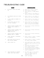
TROUBLESHOOTING GUIDE
CORRECTIVE ACTION
PROBLEM
1)
NO DISPLAY LIGHTS WITH POWER
ON.
1) Check fuse on back of Console.
2) Check battery connections.
3) Check operation of POWER ON/OFF
switch.
4) Return Console to your Dealer to
replace Processor Board Assembly.
2)
ALL KEYBOARD LIGHTS ON AT SAME
TIME.
1) Return Console to your dealer to
replace Face Plate Sub-assembly.
3)
A DIGIT CANNOT BE ENTERED VIA
KEYBOARD.
1) Return Console to your Dealer to
replace Face Plate Sub-assembly.
4)
AN INDICATOR LIGHT ON A KEY
WILL NOT ILLUMINATE.
1) Return Console to your Dealer to
replace Face Plate Sub-assembly
and/or Processor Board Assembly.
5)
CONSOLE DISPLAYS FLASHING "CAL"
WHENEVER VEHICLE ENGINE IS
STARTED.
1) Check battery voltage and battery
connections.
6)
CONSOLE DISPLAYS FLASHING "CAL"
WHENEVER MASTER SWITCH IS
TURNED ON OR OFF.
1) Check battery voltage and battery
connections.
7)
CONSOLE DISPLAYS FLASHING "CAL"
WHENEVER SPEED IS CHANGED.
1) Check battery voltage and battery
connections.
8)
"TIME" FUNCTION IS INACCURATE
OR DRIFTING.
1) Return Console to Dealer to replace
Processor Board Assembly.
9)
ONE DISPLAY DIGIT HAS ONE OR
MORE MISSING SEGMENTS.
1) Return Console to Dealer to replace
LCD Display Board Assembly.
10)
SPEED DISPLAY "0".
1) Check Speed Sensor cable connector
and plug on back of Console for loose
pins.
2) Clean pins and sockets on Speed
Sensor cable connectors.
3) If no extension cable is used,
replace Speed Sensor Switch Assembly.
4) If Speed Sensor Extension Cable is
used, see Appendix 4.
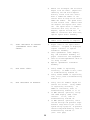
11)
SPEED INACCURATE OR UNSTABLE
(WHEEL DRIVE SPEED SENSOR).
1) Run speed check on hard surface
road. If SPEED is accurate,
investigate Speed Sensor on
different wheel.
(Cont. next page)
28
2) Remove one red magnet and one black
magnet from the wheel. (Reposition
remaining red and black magnets
directly across from each other).
Enter a SPEED CAL number in the
Console twice as large as the correct
SPEED CAL number. Run speed check
on hard surface road. Remove these
two magnets and replace with other
two. Run speed check. If SPEED is
inaccurate with only one set of
magnets, replace the bad set. If
SPEED is inaccurate with both sets,
replace Speed Sensor Assembly.
NOTE: Re-enter original SPEED CAL
number after testing is complete.
12)
SPEED INACCURATE OR UNSTABLE
(SPEEDOMETER DRIVE SPEED
SENSOR).
1) Wiggle cable at the Speed Sensor
connector. If speed is displayed,
tighten connector or replace
Transducer Assembly.
2) Check Speedometer Cable Adapter,
Key, and Transducer Assembly for
proper connections and engagement.
3) Check for kinked speedometer cable or
too sharp of bend.
4) Replace Speedometer Transducer
Assembly.
13)
RATE READS "0000".
1) Verify SPEED is registering
accurately. If SPEED is zero, refer
to Troubleshooting Problem 10.
2) Verify TOTAL VOLUME is registering
flow. If not, refer to Troubleshooting
Problem 17.
14)
RATE INACCURATE OR UNSTABLE.
1) Verify that all numbers "keyed in"
Console are correct. Verify SPEED
is registering accurately. If
SPEED is inaccurate, refer to
Troubleshooting Problem 11 or 12.
2) In MAN (manual) operation, verify
that RATE display (GPA) holds
constant. If not, refer to
Troubleshooting Problem 18.
3) In MAN (manual) operation, check
low end and high end pressure range.
Pressure range must be per initial
system set-up on page 26. If pressure
cannot be adjusted manually, refer to
Troubleshooting Problem 17.
(Cont. next page)
29
15) CAN NOT VARY RATE IN MANUAL
OPERATION OR IN AUTO.
4)
If problem persists, return Console
to Dealer to replace Processor
Board Assembly.
1)
Check cabling to motorized Control
Valve for breaks.
Check connections in cabling for
cleanliness.
Verify that there is voltage at the
valve connector by placing MASTER
switch ON; RATE 1/RATE 2/MAN switch
to MAN; and POWER switch to ON.
Manually operate INC/DEC switch
to verify voltage.
Verify that valve is turning, if not,
replace motorized Control Valve.
2)
3)
4)
16) SPRAYER PRESSURE IS CORRECT BUT
RATE IS LOW.
1)
2)
3)
17) TOTAL VOLUME DOES NOT REGISTER.
1)
2)
3)
Verify that nozzle strainer screens
or check valves are not plugged.
Verify that pressure at each boom is
the same.
Verify all nozzles are of proper and
same orifice size. See Page 12 of
Installation Manual.
Check Flow Meter Cable for breaks and
shorts. See Appendix 5 for test
procedure.
Check internals of Flow Meter; clean
and adjust. See Appendix 6 for Flow
Meter cleaning and adjustments.
Replace Flow Meter Transducer.
18) TOTAL VOLUME REGISTERS FLOW
INACCURATELY.
1)
Verify that arrow on Flow Meter is
pointing in direction of flow. See
Appendixes 6 and 7.
19) MOTORIZED CONTROL VALVE ROTATES
MORE THAN 1/4 TURN.
1)
Replace motorized Control Valve.
20) WATER INSIDE COVER OF MOTORIZED
CONTROL VALVE.
1)
Replace Isolation Flange Assembly
and coupler shaft.
Replace entire motorized Control
Valve, if PC board or motor is
corroded and will not run.
2)
21) BOOM VALVE(S) WILL NOT OPERATE.
1)
2)
3)
4)
30
Check cable for wires with breaks.
Check connectors for cleanliness.
Check BOOM switch and MASTER switch
for operation.
Replace Boom Valves.
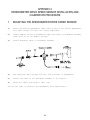
APPENDIX 1
WHEEL DRIVE SPEED SENSOR INSTALLATION AND CALIBRATION
PROCEDURE
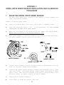
1.
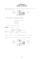
MOUNTING WHEEL DRIVE SPEED SENSOR
The Wheel Drive Speed Sensor consists of four magnets, a switch assembly with
cable, and mounting hardware.
Sequence of mounting Speed Sensor:
l)
Select a non-driven wheel (left front tractor wheel or implement wheel).
2)
Check for predrilled holes in rim.
If not predrilled, see "RIM DRILLING
INSTRUCTIONS FOR WHEEL DRIVE SPEED SENSOR".
3)
Mount the four magnets to the inside of rim and tighten (See Figures below).
Magnets must be mounted in alternating red-black order.
4)
Mount switch assembly to stationary column with the hardware provided (See below).
The switch assembly need not pivot with the wheel.
SWITCH ASSEMBLY
MAGNET ASSEMBLY
MAGNET LOCATION
5)
Position switch assembly so that as the wheel rotates the magnets pass across the
center of the black, molded switch assembly.
6)
Clearance gap between magnets and switch assembly must be between 1/4 inch [6 mm]
and 1 inch [25 mm]. With wheels pointed straight ahead, rotate wheel to ensure
gap is correct. Make sure vehicle wheels can be turned to their extremes in each
direction without the magnets hitting the switch assembly.
7)
Tighten switch assembly bracketry.
8)
Secure cable to column with plastic cable ties.
31
2.
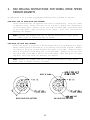
RIM DRILLING INSTRUCTIONS FOR WHEEL DRIVE SPEED
SENSOR MAGNETS
On wheels which do not have pre-punched mounting holes, proceed as follows:
RIMS WITH FOUR OR EIGHT HOLE STUD PATTERN:
Choose stud holes that are opposite each other as shown below. Using the center
of opposite holes, scribe two lines on the rim web to divide the circumference
into four equal parts. Measure in one inch from the outer edge of the web on each
of the lines drawn. Mark this point as the center. Drill four 1/2" holes for
mounting the magnets.
NOTE: Distance (D) between each set of drilled holes must be equal within
1/8" [3 mm] to ensure accuracy of system.
RIMS WITH SIX HOLE STUD PATTERN:
Locate the center of the holes to be drilled by using the rim webbing as a guide.
Obtain a small piece of wood and cut to fit exactly over the web as shown. Measure
the length of the piece of wood and mark the center on one edge. Using the center
mark on the piece of wood, mark each of the four webs. Measure in one inch from
the outer edge of the web on each of the lines drawn. Mark this point as center
and drill four 1/2" holes for mounting the magnets.
NOTE: Distance (D) between each set of drilled holes must be equal within
1/8" [3 mm] to ensure accuracy of system.
EIGHT HOLE STUD PATTERN
SIX HOLE STUD PATTERN
32
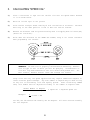
3.
CALCULATING "SPEED CAL"
1)
Place a chalk mark or tape onto the vehicle tire that the Speed Sensor mounted
to it as shown below.
2)
Mark the initial spot on the ground.
3)
Drive vehicle straight ahead counting 10 full revolutions of the wheel. The mark
must stop at the same position it was in when the vehicle started.
4)
Measure the distance from the ground starting mark to stopping mark in inches [dm]
(Round off fractions).
5)
Write down this distance as the SPEED CAL number; keep it for future reference
when programming the Console.
NOTE: This measurement is critical to the performance of the Console. MEASURE
CAREFULLY. Be sure tire is properly inflated before measuring. Measure
tire in type of soil in which you will be spraying. Circumference of
tire will vary when measured in soft soil versus hard packed soil. For
best results, measure several times and average the results.
Large tires and very low speed applications may require additional magnets to
insure accurate speed readings. Any even number of magnets may be used as long
as they are of alternating color and equally spaced. After calculating "SPEED
CAL", this number must be adjusted according to the number of magnets used.
Normal Number of Magnets
Actual Number of Magnets
Example:
4
6
x Speed Cal = Adjusted Speed Cal
x 1200 = 800
SCS 330, SCS 500 and SCS 550 normally use two magnets. All other consoles normally
use four magnets.
33
APPENDIX 2
SPEEDOMETER DRIVE SPEED SENSOR INSTALLATION AND
CALIBRATION PROCEDURE
1.
MOUNTING THE SPEEDOMETER DRIVE SPEED SENSOR
1)
Remove the existing speedometer cable from the back of the vehicle speedometer.
Pull cable through fire wall into engine compartment.
2)
Install adapter and key on speedometer cable and connect to Transducer Assembly.
(Some units do not use adapter and key).
3)
Connect Extension Cable to Transducer Assembly.
4)
Push Extension Cable through fire wall and re-install on speedometer.
5)
Connect the cable on the Transducer Assembly to the Console.
6)
Secure all cables with plastic cable ties.
You are now ready to calibrate the Speedometer Drive Speed Sensor.
34
2.
CALCULATING "SPEED CAL"
1)
Complete "INITIAL CONSOLE PROGRAMMING" before doing this procedure.
2)
Enter “0” in key labelled
3)
Enter a SPEED CAL of 612 [155] in key labelled
4)
Drive 1 mile [1 km].
CAUTION:
5)
Do not use vehicle odometer to determine distance.
lines or Highway markers.
Use section
Read DISTANCE by depressing key labelled
a)
DISTANCE should read a value of approximately 5280 [1000]. If it reads
between 5200-5350 [990-1010], the SPEED CAL for your vehicle is 612 [155].
b)
If the DISTANCE display reads any other value, perform the following
calculation:
Multiply the SPEED CAL by the target distance reading, then divide the sum
by the actual value in DISTANCE display. This will give you the corrected
value to enter for SPEED CAL. You must round off to the nearest 3 digit
whole number.
EXAMPLE:
=
SPEED CAL = 612 [155]
Target distance reading = 5280 [1000]
Assume the actual DISTANCE display reads 5000 [980]
ENGLISH UNITS:
612 x 5280 = 646.3
5000
METRIC UNITS:
= [155] x [1000] = [158.1]
[980]
6)
The corrected number to enter for SPEED CAL is 646 [158].
7)
Verify the corrected SPEED CAL number calculated above:
a)
Zero out the DISTANCE display as in Step 2.
b)
Enter the corrected SPEED CAL number as in Step 3.
c)
Repeat Steps 4 and 5a.
Steps 5b, 6, and 7.
If DISTANCE value does not read correctly repeat
35
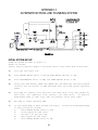
APPENDIX 3
ALTERNATE BY-PASS LINE PLUMBING SYSTEM
FIGURE 11
INITIAL SYSTEM SET-UP
Plumb the system as shown in Figure 11.
Adjust as follows:
Install Polarity Reversal Jumper in motorized Control Valve Cable (P/N 115-0159-415).
1)
Fill tank with water only.
2)
Place MASTER ON/OFF switch to ON and BOOM ON/OFF switches to OFF.
3)
Place AUTO/MAN/OFF switch to MAN, and POWER ON/OFF switch to ON.
4)
Verify that Boom Widths, SPEED CAL, METER CAL, and RATE CALS have been entered
correctly into the Console. In SELF TEST mode enter the normal sprayer operating
speed.
5)
With pump not running, fully open main line hand valve, fully open by-pass #1
hand valve, and completely close agitator line hand valve.
If positive
displacement pump is used, fully open the pressure relief valve (PRV).
6)
Run pump at normal operating RPM.
7)
If centrifugal pump is used, proceed with Step 8.
is used, proceed as follows:
a)
Place MASTER ON/OFF switch to OFF.
b)
Close by-pass #1 hand valve.
c)
Set PRV to 65 psi [450 kPa].
d)
Open by-pass #1 hand valve.
e)
Place MASTER ON/OFF switch to ON.
36
If positive displacement pump
8)
Verify that each boom valve operates and that no nozzles are plugged by operating
the BOOM ON/OFF switches.
9)
Place all BOOM ON/OFF switches to ON.
10)
Hold the FLOW CONTROL switch to INC position for approximately 12 seconds. This
assures motorized Control Valve is fully closed. (Pressure gauge is not supplied).
NOTE: A pressure gauge MUST be installed to properly adjust the system.
11)
Adjust agitator line hand valve for desired agitation.
12)
Close the main line hand valve, if necessary, to set the desired maximum
operating pressure. Maximum pressure should be approximately 10 psi [70 kPa] above
normal spraying pressure.
EXAMPLE: If normal spraying pressure is 30 psi [210kPa], set maximum pressure at
approximately 40 psi [280 kPa].
13)
Hold the MAN ADJ switch to DEC position for approximately 12 seconds. This assures
motorized Control Valve is fully open.
14)
Close by-pass #1 hand valve to set the desired minimum operating pressure. Minimum
pressure should be approximately one half the normal spraying pressure.
EXAMPLE: If normal spraying pressure is 30 psi [210 kPa], set minimum pressure
at approximately 15 psi [105 kPa].
15)
Verify maximum and minimum pressures and RATE by repeating Steps 11 and 14.
INITIAL SYSTEM FIELD TEST
1)
Drive down field or road at target speed with sprayer booms OFF, to verify SPEED
readout on Console.
2)
Turn on sprayer and booms and place the MAN/AUTO switch to AUTO. Increase or
decrease speed by one (1) MPH [2 km/h]. The system should automatically correct
to the target application rate.
3)
If for any reason, the system is unable to correct to the desired RATE, check for
an empty tank, a plugged line, a malfunctioning pump, improper vehicle speed or
a defect in the system.
4)
If the system does not appear to be correcting properly, first review INITIAL
SYSTEM SET-UP, then refer to TROUBLESHOOTING GUIDE.
5)
At the end of each row, switch the MASTER ON/OFF to OFF to shut off flow.
also shuts off the area totalizer.
6)
Verify area covered and volume used.
37
This
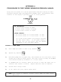
APPENDIX 4
PROCEDURE TO TEST SPEED SENSOR EXTENSION CABLES
Verify that the Console is in the SP1 Speed Sensor mode while testing the cable.
Disconnect extension cable from Speed Sensor Assembly cable. Hold extension cable
connector so that keyway is pointing in the 12 o’clock position.
PIN DESIGNATIONS
2 o’clock socket location is power.
10 o’clock socket location is ground.
6 o’clock socket location is signal.
VOLTAGE READINGS
1) 10 o’clock socket to 6 o’clock socket = +5 VDC.
2) 10 o’clock socket to 2 o’clock socket = +5 VDC.
If a +5 VDC voltage reading is not present, disconnect
the Flow Sensor cable.
If the Speed reading is
restored, Test the Flow Sensor cable per Appendix
"PROCEDURE TO TEST FLOW METER CABLES".
PROCEDURE TO CHECK CABLE:
.
l)
Enter SPEED CAL number of 1000 in key labelled
2)
Depress key labelled
3)
With small jumper wire (or paper clip), short between the 10 o’clock and 6 o’clock
sockets with a "short-no short" motion. Each time a contact is made, the DISTANCE
total should increase by increments of 1 or more counts.
4)
If DISTANCE does not increase, remove the section of cable and repeat test at
connector next closest to Console. Replace defective cable as required.
5)
Perform above voltage checks.
6)
If all cables test good, replace Speed Sensor.
.
NOTE: After testing is complete, re-enter correct SPEED CAL number before
application.
38
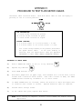
APPENDIX 5
PROCEDURE TO TEST FLOW METER CABLES
Disconnect cable from Flow Sensor. Hold Flow Sensor cable so that the keyway is
pointing in the 12 o’clock position:
PIN DESIGNATIONS
2 o’clock socket location is ground.
10 o’clock socket location is power.
6 o’clock socket location is signal.
VOLTAGE READINGS
1) 2 o’clock socket to 6 o’clock socket = +5 VDC.
2) 2 o’clock socket to 10 o’clock socket = +5 VDC.
If a +5 VDC voltage reading is not present, disconnect
the Speed Sensor cable.
If the Flow reading is
restored, Test the Speed Sensor cable per Appendix
"PROCEDURE TO TEST SPEED SENSOR EXTENSION CABLES".
PROCEDURE TO CHECK CABLE:
1)
Enter a METER CAL number of one (1) in key labelled
.
2)
Depress key labelled
3)
Place BOOM switches to ON.
4)
With small jumper wire (or paper clip), short between the 2 o’clock and 6 o’clock
sockets with a "short-no short" motion. Each time a contact is made, the TOTAL
VOLUME should increase by increments of 1 or more counts.
5)
If TOTAL VOLUME does not increase, remove the section of cable and repeat test
at connector next closest to Console. Replace defective cable as required.
6)
Perform above voltage checks.
7)
If all cables test good, replace Flow Sensor.
.
NOTE: After testing is complete, re-enter correct METER CAL numbers before
application.
39
APPENDIX 6
FLOW METER MAINTENANCE AND ADJUSTMENT PROCEDURE
1)
Remove Flow Meter from sprayer and flush with clean water to remove any chemicals.
NH3 WARNING: Thoroughly bleed nurse tank hose and all other system lines prior
to disassembling the Flow Meter, fittings, and hoses.
2)
Remove flange bolts or clamp from the Flow Meter.
3)
Remove the turbine hub and turbine from inside Flow Meter.
4)
Clean turbine and turbine hub of metal filings or any other foreign material, such
as wettable powders. Confirm that the turbine blades are not worn. Hold turbine
and turbine hub in your hand and spin turbine. The turbine should spin freely
with very little drag inside the turbine hub.
5)
If transducer assembly is replaced or if turbine stud is adjusted or replaced,
verify the turbine fit before reassembling. Hold turbine hub with turbine on
transducer. Spin turbine by blowing on it. Tighten turbine stud until turbine
stalls. Loosen turbine stud 1/3 turn. The turbine should spin freely.
6)
Re-assemble Flow Meter.
7)
Using a low pressure (5 psi) [34.5 kPa] jet of air, verify the turbine spins freely.
If there is drag, loosen hex stud on the bottom of turbine hub 1/16 turn until
the turbine spins freely.
8)
If the turbine spins freely and cables have been checked per Appendix "PROCEDURE
TO TEST FLOW CABLES", but Flow Meter still is not totalizing properly, replace
Flow Meter transducer.
40
APPENDIX 7
PROCEDURE TO RE-CALIBRATE FLOW METER
1)
Enter a METER CAL number of 10 [38] in the key labelled
2)
Enter a TOTAL VOLUME of 0 in the key labelled
3)
Switch OFF all booms.
4)
Remove a boom hose and place it into a calibrated 5 gallon [19 liter] container.
5)
Switch ON appropriate boom switch (for the hose that was just placed into the 5
gallon container) and the MASTER switch. Pump exactly 10 gallons [38 liters].
6)
Readout in TOTAL VOLUME is the new METER CAL number. This number should be within
+/- 3% of the calibration number stamped on the tag of the Flow Meter.
7)
Repeat this procedure several times to confirm accuracy. (Always "zero out" the
TOTAL VOLUME display before retesting).
NOTE: For greatest precision, set METER CAL to 100 and pump 100 gallons (378
liters) of water.
8)
To verify Flow Meter calibration, fill applicator tank with a predetermined amount
of measured liquid (i.e. 250 gallons). DO NOT RELY ON GRADUATION NUMBERS MOLDED
INTO APPLICATOR TANK.
Empty the applicator tank under normal operating
conditions. If the number displayed under TOTAL VOLUME is different from the
predetermined amount of measured liquid by more than +/- 3%, complete the following
calculation:
EXAMPLE:
METER CAL
TOTAL VOLUME
Predetermined amount of measured liquid
Corrected METER CAL
=
METER CAL x TOTAL VOLUME
Predetermined amount of measured liquid
ENGLISH UNITS:
= 720 x 260 = 749
250
Corrected METER CAL
9)
= 720 [190]
= 260 [984]
= 250 [946]
METRIC UNITS:
= [190] x [984] = [198]
[946]
= 749 [198]
Enter corrected METER CAL before resuming application.
41
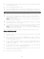
APPENDIX 8
REMOTE SWITCH OPTION
FIGURE 12
The REMOTE switch when installed is in parallel with the MASTER switch; therefore
switching on the REMOTE switch OR the MASTER switch will energize the boom valves.
42
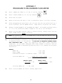
APPENDIX 9
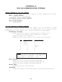
SERIAL INTERFACE
1) Cable pinout (P/N 115-0159-994), supplied with Thermal Printer Kit
(P/N 117-0159-529).
DSR 6
5
CTS
8
RAVEN
Printer
DTR 4
6
CONSOLE
25 Pin
TXD 3
2
9 PIN
RXD 2
3
GND 5
7
2) Changing RATE 1 CAL by remote computer.
a) Configuration of RS-232C serial port:
1200 or 9600 Baud Rate
NO Parity
8 Data Bits
2 Stop Bits
b) Data stream to Raven Console.
EXAMPLE: Change RATE 1 to 123.4
$R,RC,1234<CR><LF>
Line Feed
Communication
string
Rate Cal
RATE 1
= 123.4
Carriage Return
Decimal point is not sent from Remote Computer to Raven Console.
3) Optional 9 pin to 9 pin cable pinout (P/N 115-0159-822).
RAVEN
CONSOLE
9 PIN
DSR 6
CTS 8
DTR 4
4
6
8
2
3
5
TXD 3
RXD 2
GND 5
43
COMPUTER/
GPS
9 Pin
APPENDIX 10
SCS 440 COMMUNICATION STRINGS
REMOTE COMPUTER TO SCS 440 CONSOLE
All request strings begin with $R, to indicate a Raven communication string.
Rate 1 Change Request:
$R,RC,<rate_1_cal><CR><LF>
Calibration String Values Request:
$R,CR<CR><LF>
Data String Request:
$R,DR<CR><LF>
SCS 440 CONSOLE TO REMOTE COMPUTER
All console output strings begin with $R035J, the $R indicates a Raven
communication string, the 035 is the last three digits of the current SCS 440
programmed chip part number and J is the software revision number.
Calibration Strings:
$R035J,C1,<switch_byte_1>,<switch_byte_2>,<boom_1_cal>,
<boom_2_cal>,<boom_3_cal>,<speed_cal> <CR><LF>
$R035J,C2,<meter_cal>,<CR><LF>
$R035J,C3,<valve_cal>,<rate_1_cal>,<rate_2_cal><CR><LF>
Bit
0
1
2
3
4
5
6
7
Switch Byte 1
boom 1
boom 2
boom 3
0
0
0
0
1
Switch Byte 2
0
0
0
rate 1
rate 2
0
0
1
NOTE: If rate 1 and rate 2 are both zero,
the console is in Manual. For switch
Byte Bits; 0 = off and 1 = on.
Data Strings:
$R035J,D1,<total_area>,<field_area><CR><LF>
$R035J,D2,<total_volume>,<field_volume><CR><LF
$R035J,D3,<tank_volume>,<distance><CR><LF>
Actual Rate:
$R035J,AR,<actual_rate><CR><LF>
Time/Date:
$R035J,TD,<hr:min>,<month/day/year>,<field_reference><CR><LF>
44