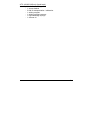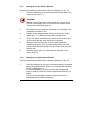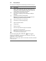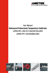
1
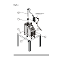
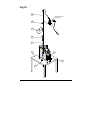
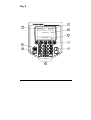
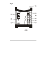
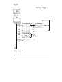
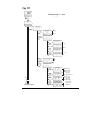
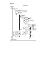
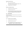
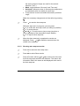
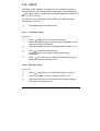
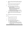
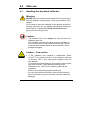
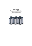
User Manual Temperature Calibrator JOFRA ATC-125/140/156/157/250/320/650 A/B Copyright 2005 AMETEK DENMARK A/S (105447-UK) 13-03-2007 Fig 1a (calibrator view) 6 Reference sensor (if available) 5 RAT LI B CA ION INS S E NT UM TR F5 F4 F3 F2 i 6 5 4 ESC 9 8 7 3 2 1 _ 0 . 1 F1 3 4 2 13-03-2007 Fig 1b 9 Reference sensor (if available) 8 5 4 3 CA TIO RA LIB N INS EN UM TR TS F5 F3 F4 9 F2 1 8 F1 7 6 5 4 C ES i 3 2 1 _ 0 6 7 2 (calibrato r 13-03-2007 Fig. 2 (display and keyboard) 7 CALIBRATION INSTRUMENTS 6 (heading) (icon) 8 (information) 9 (functions) 1 5 2 4 3 13-03-2007 Fig 3 (connections both A and B versions) 11 Fuse 230V 5AF/115V 10AF + TC 1 + Switch Test - - 115V . 5V MAX . 10 45V MAX 9 + mA Act. + mA Pas. 2 - Sync. 8 V + 3 RS232 7 6 Ref. Input 4 13-03-2007 5 Fig 4 Calibrator Overview I SET temp. Run calibration Calibration Show calibration Run switch test Switch test Show results Auto step Run auto step Show results Setup See Calibrator Overview cont. 13-03-2007 Fig 5 (c I Calibrator Overview cont. SET temp. Calibration See Calibrator Overview Switch test Auto step Load setup Setup Save setup Display contrast (ATC-140/250 A/B only) Temperature More More More More Input Input Stirrer Stability criteria Stability criteria Access code More More More More Access code Factory defaults Factory defaults About About a 13-03-2007 lFig 6 (calib Calibration Edit Run calibration Next Copy work order Next No No Yes Yes Calibration info see Calibration information Start calibration No Yes Stop calibration Finish Show results 13-03-2007 Fig 7 (calibration 2) Calibration information 13-03-2007 Fig 8 (switch test) Switch Test Overview Switch test Yes Finish No Stop sw. test Run switch test Start Show result Back to sw test Show results Sw. test setup Back to sw test Sw. test setup Finish 13-03-2007 Back to result Fig 9 (auto step) Auto-step Overview Auto step Yes No Stop auto step Run auto step Start Auto step result Back to auto step Show results Finish Pause Back to auto step Auto step setup Finish 13-03-2007 Back to result Fig 10 (setup 1) Setup page 1 Setup Load Load setup Yes No Save setup Display contrast Temperature Save Less More Setup page 1 cont. More Setup page 2 13-03-2007 Fig 11 (setup 1b) Setup page 1 cont. Setup Temperature °C Unit °F °K Resolution SET 1 READ 0.1 TRUE 0.01 SENSOR Max. SET temp. Edit Convert to temp. Voltage 0-4V Low voltage Low volt temp. Voltage 0-12V High voltage High voltage temp. More Current 4-20mA Cold junc. compens. Setup page 2 Low current Low curr.temp. High current High curr. temp. Compens. mode Manual value 13-03-2007 Fig 12 (setup 2) Setup page 2 Setup page 1 More Input Select source - Internal Reference sensor Select source - External Convert to temperature SET follows TRUE Sensor u. test Type of sensor 0-4V Voltage 0-12V Current 4-20mA Type of sensor Convert to temperature Yes/No RTD Pt10 (IEC) Pt50 (P) Pt100 (IEC, Mill, P) Pt500 (IEC) E J K L Thermo couples Edit More More Convert to temperature Stability criteria More More N R S None More More Type of sensor Access code Edit Convert to temperature Yes/No More T U XK (Russian) More More Setup page 3 13-03-2007 Pt1000 (IEC) Cu50 (M, Cu) Cu100 (M, Cu) Fig 13 (setup 3) Setup page 3 Setup page 2 More No Factory defaults No Yes About 13-03-2007 Exit Yes Fig 14 Stirrer speed Setup More Stirrer menu Edit Accept 13-03-2007 13-03-2007 List of contents 1.0 Introduction ..............................................................................3 1.1 List of equipment received............................................................ 4 2.0 3.0 Safety instructions ...................................................................6 Operating the calibrator.........................................................11 3.1 Before use................................................................................... 11 3.1.1 Setting up the dry-block calibrator.................................. 12 3.1.2 Setting up the liquid bath calibrator................................ 12 3.2 During use................................................................................... 16 3.3 Keyboard..................................................................................... 17 3.4 Display ........................................................................................ 17 3.5 Connections ................................................................................ 18 3.6 Calibrator functions – overview .................................................. 19 3.7 Setting the speed level of the stirrer (liquid baths only).............. 19 3.8 Selecting the SET temperature .................................................. 20 3.9 Calibration................................................................................... 20 3.9.1 Running a calibration...................................................... 20 3.9.2 Showing calibration results ............................................ 22 3.10 SWITCH TEST............................................................................ 22 3.10.1 Running a switch test..................................................... 23 3.10.2 Showing switch test results............................................ 23 3.11 AUTO STEP................................................................................ 24 3.11.1 Running an auto step calibration ................................... 24 3.11.2 Showing auto step test results....................................... 25 3.12 SETUP ........................................................................................ 26 3.12.1 Loading a setup ............................................................. 26 3.12.2 Saving a setup ............................................................... 26 3.12.3 Adjusting the display contrast ........................................ 27 3.12.4 Altering the temperature display settings....................... 27 3.12.5 Setting the sensor input parameters (B-versions only) . 29 3.12.6 Altering stability criteria .................................................. 31 3.12.7 Setting the access code................................................. 32 3.12.8 Resetting the calibrator setup to factory defaults .......... 32 3.12.9 About the calibrator........................................................ 33 4.0 5.0 Setting the mains voltage and replacing the fuses.............34 After use..................................................................................36 5.1 Handling the dry-block calibrator ................................................ 36 105447 05 1 5.2 Handling the liquid-bath calibrator .............................................. 37 2 105447 05 1.0 Introduction This user manual applies to the following instruments: • • • • • • • • • • • • • • JOFRA ATC-125 A – Cooling calibrator JOFRA ATC-125 B – Cooling calibrator with input panel JOFRA ATC-140 A – Cooling calibrator JOFRA ATC-140 B – Cooling calibrator with input panel JOFRA ATC-156 A – Cooling calibrator JOFRA ATC-156 B – Cooling calibrator with input panel JOFRA ATC-157 A – Cooling calibrator JOFRA ATC-157 B – Cooling calibrator with input panel JOFRA ATC-250 A – Heating calibrator JOFRA ATC-250 B – Heating calibrator with input panel JOFRA ATC-320 A – Heating calibrator JOFRA ATC-320 B – Heating calibrator with input panel JOFRA ATC-650 A – Heating calibrator JOFRA ATC-650 B – Heating calibrator with input panel These instruments are temperature calibrators designed to calibrate temperature sensors and thermostats. The ATC-125/156/157/320/650 A/B instruments are all designed as dry-block calibrators, where as the ATC-140/250 A/B instruments are designed to be used both as dry-block calibrators and liquid baths. Read this manual carefully before using the instrument and ensure that all safety instructions and warnings are observed. 105447 05 3 1.1 List of equipment received When you receive the instrument, the following should be enclosed: • • • • • • • • • • 1 calibrator 1 mains cable 2 sets of test cables (2 black, 2 red – only B-versions) 1 CD-ROM containing software package “JOFRACAL” 1 AMETRIM-ATC/DTI software package to adjust the ATC series 1 RS232 serial cable 1 tool for insertion tube 1 traceable certificate (A versions) 2 traceable certificates (B versions) 1 reference manual 1 user manual ATC-125/156/157/320/650 A/B only • 1 insertion tube – user specified (incl. reference bore) • 3 pcs. insulation plugs for 6, 10, 16 mm sensors (ATC-125/156 A/B only) or 3 pcs. insulation plugs for 5, 8, 11 mm sensors (ATC-157 A/B only) ATC-140/250 A/B only (dry-block) • 1 dry block kit – metric consisting of : - 1 insertion tube, multi-hole, metric, with 11 bores (incl. reference bore) - 1 pcs. insulation plug for multi-hole, metric (ATC-140 A/B only) or • 1 dry block kit – inch consisting of : - 1 insertion tube, multi-hole, inch, with 11 bores (incl. reference bore) - 1 pcs. insulation plug for multi-hole, inch (ATC-140 A/B only) 4 105447 05 ATC-140/250 A/B only (liquid bath) • 1 liquid bath kit consisting of : - 1 sensor basket - 2 lids for transportation / calibration - 1 stirring magnet - 1 stirring magnet remover - 1 liquid drainage syringe - 1 silicone oil 105447 05 5 2.0 Safety instructions Read this manual carefully before using the instrument! In order to avoid any personal injuries and/or damage to the instrument all safety instructions and warnings must be observed. Disposal – WEEE Directive These calibrators contain Electrical and Electronic circuits and must be recycled or disposed of properly (in accordance with the WEEE Directive 2002/96/EC). Warning…… About the use: • • • • • 6 The calibrator must not be used for any purposes other than those described in this manual. The calibrator has been designed for interior use only and should not be used in hazardous areas, where vapour or gas leaks, etc. may constitute a danger of explosion. The calibrator must be kept free within an area of 20 cm on all sides and 1 metre above the calibrator. NEVER use heat transfer fluids such as silicone, oil, paste, etc. in the dry-block calibrators. These fluids may penetrate the calibrator and cause damage or create poisonous fumes. When cleaning the well, REMEMBER to wear goggles when using compressed air in the dry-block calibrator and cleaning oil in the liquid bath calibrator. 105447 05 • The ATC-125 contains the gases R-1270 and R-704 under pressure. The calibrator must under no conditions be stored or operated at ambient temperatures above 60°C (140°F) About the front panel: • For B versions only, the sockets on the input module must NEVER be connected to voltages exceeding 5V for the TC/RTD sockets and 45V for the mA/V sockets proportional to ground. Thermostats must not be connected to any other voltage sources during test. About the insertion tubes and sensor: • NEVER leave hot insertion tubes which have been removed from the calibrator unsupervised – they may constitute a fire hazard. If you intend to store the calibrator in the optional aluminium carrying case after use, you must ensure that the instrument has cooled down to a temperature below 100°C/212°F before placing it in the carrying case. About the fuses: • • The fuse box must not be removed from the power control switch until the mains cable has been disconnected. The two main fuses must be identical and correspond to the chosen voltage. About the liquid bath: • • 105447 05 Ensure that the sensor is absolutely clean and dry as a few drops of water in the well (liquid bath) might cause a steam explosion. AMETEK Denmark A/S does not take any responsibility, if the well is filled with other fluids than the recommended. 7 • • • • • • Heat transfer fluids must only be used in calibrators prepared as a liquid bath. If these fluids are overheated they will create noxious or toxic fumes. Proper ventilation must be used. Product information on the fluid must be carefully investigated before use. Do not handle hot oil. If the oil is heated beyond the flash point, it may constitute a fire hazard. Always set the max. SET temperature to a temperature 20°C below the flash point. Do not pour cold oil into a hot well – it might cause an explosion. Do not pour water or any other liquid into a bath filled with hot oil. E.g. only a few drops of water might cause a steam explosion, if poured into 250°C hot oil. Caution – Hot surface This symbol is engraved in the grid plate. • Do not touch the grid plate, the well or the insertion tube when the calibrator is heating up – they may be very hot. • Do not touch the lid or the spill tray when the calibrator is heating up – they may be very hot (liquid baths only). • Do not touch the tip of the sensor when it is removed from the insertion tube/well – it may be very hot. • 8 Do not touch the handle of the calibrator during use – it may be very hot. 105447 05 Caution – Cold surface • • If the calibrator has reached a temperature below 0°C/32°F, ice crystals may form on the insertion tube and on the well. This, in turn, may cause verdigris to form on the material. To prevent this from happening, the insertion tube and the well must be dried. This is done by heating up the calibrator to min. 100°C/212°F and any water left will evaporate. Remove the insulation plug while heating up. It is very important that humidity in the well and insertion tube is removed to prevent corrosion and frost expansion damages. Do not touch the well or insertion tube when these are below 0°C/32°F – they can create frost-bites. Caution… About the use: • Do not use the instrument if the internal fan is out of order. About the liquid bath: • • • Be careful not to overfill the well with oil. The oil level rises several centimetres when the temperature is rising to maximum. Do not attempt to remove hot oil overflow with the liquid drainage tube, as it might melt. When heated to high temperatures the liquid bath calibrator should be placed under an exhaust hood to remove any vapors given off by the oil. About the insertion tube and sensor: • 105447 05 The tip of the sensor should rest at the bottom of the sensor basket for optimum results (liquid baths only). 9 • • If the sensor-under-test is short, be careful not to submerge the handle or wire inlet in the oil, as this might damage the sensor (liquid baths only). The insertion tube must always be removed from the calibrator after use. The humidity in the air may cause corrosion oxidation on the insertion tube inside the instrument. There is a risk that the insertion tube may get stuck if this is allowed to happen. Note… The product liability only applies if the instrument is subject to a manufacturing defect. This liability becomes void if the user fails to follow the instructions set out in this manual or uses unauthorised spare parts. 10 105447 05 3.0 Operating the calibrator 3.1 Before use The ATC-B-version has a precision reference input. To achieve the high precision, a set of sensor coefficients relating to the specific sensor must be present in the ATC. Before use of the ATC, ensure that the correct coefficients in the ATC are equal to those from the sensors calibration certificate. This is done with the PC software JOFRACAL included on the CD. Please read how to do in the chapter “Reference Sensors” in the JOFRACAL user manual on the CD. Warning • The calibrator must not be used for any purposes other than those described in this manual. • The calibrator has been designed for interior use only and should not be used in hazardous areas, where vapour or gas leaks, etc. may constitute a danger of explosion. • For B versions only, the sockets on the input module (fig. 3) must NEVER be connected to voltages exceeding 5V for the TC/RTD sockets and 45V for the mA/V sockets proportional to ground. Thermostats must not be connected to any other voltage sources during test. • NEVER use heat transfer fluids, such as silicone, oil, paste, etc. to help inserting sensors in dry-block calibrators. These fluids may penetrate the calibrator and cause damage or create poisonous fumes. • The calibrator must be kept free within an area of 20 cm on all sides and 1 metre above the calibrator. • The ATC-125 contains the gases R-1270 and R-704 under pressure. The calibrator must under no conditions be stored or operated at ambient temperatures above 60°C (140°F). 105447 05 11 3.1.1 Setting up the dry-block calibrator Follow the instructions below before using the calibrator (cf. fig. 1a) 1. Place the calibrator on an even horizontal surface where you intend to use it (pos. 1). Caution… Do not use the instrument if the internal fan is out of order. Ensure a free supply of air to the internal fan located at the bottom of the instrument (pos. 2). 2. The area around the calibrator should be free of draught, dirt, flammable substances, etc. 3. Check that the voltage setting, shown on the power control switch (pos. 3), is identical to the mains voltage used. 4. Plug in the mains cable below the power control switch (pos. 4) and check that the earth connection is present. 5. Select an insertion tube (pos. 5) with a boring diameter matching the sensor (pos. 6) to be calibrated. Ensure that both the well and the insertion tube are clean. Insert the tube into the well. 6. Place the sensor (pos. 6) in the insertion tube (pos. 5) as shown in fig. 1a. 3.1.2 Setting up the liquid bath calibrator Follow the instructions below before using the calibrator (cf. fig. 1b). 1. 12 Place the calibrator on an even horizontal surface in that place where you intend to use it. Place it in a way that will minimize the risk of tilting (pos. 1). It is recommended to cover the surface with a disposable cover in order to protect the surface against the silicone oil, if spilled. It is also recommendable to have a sufficient amount of disposable paper towels within reach. 105447 05 Caution… Do not use the instrument if the internal fan is out of order. Ensure a free supply of air to the internal fan located at the bottom of the instrument (pos. 2). 2. The area around the calibrator should be free of draught, dirt, flammable substances, etc. 3. Place the parts from the liquid bath kit in the well in the following order : A. stirring magnet (pos. 3) B. sensor basket (pos.4) C. silicone oil (pos. 5) The recommended oil volume to a given test temperature is listed in the tables below. The recommended volumes must be adjusted to the actual job. ATC-250 A/B For recommended 50 cSt oil 0°C - 50°C 100% 50°C - 100°C 95% 100°C - 150°C 90% 150°C - 200°C 85% 200°C - 250°C 80% ATC-140 A/B For recommended 10 cSt oil -20°C - 50°C 100% 50°C - 100°C 95% 100°C - 140°C 90% Warning • • 105447 05 Do not pour cold oil into a hot well – it might cause an explosion. AMETEK Denmark A/S does not take any responsibility, if the well is filled with other fluids than those recommended. 13 Caution… • Be careful not to overfill the well with oil. The oil level rises several centimetres when the temperature is rising to maximum. • Do not attempt to remove overflow of hot oil with the liquid drainage syringe, as it might melt. 4. The sensor basket (pos. 4) is marked with an optimum oil level mark (100%). When filling the well with oil and placing the sensors, this mark must never be exceeded. 5. Check that the voltage setting, shown on the power control switch (pos. 6), is identical to the mains voltage used. 6. Plug in the mains cable below the power control switch (pos. 7) and check that the earth connection is present. Switch on the calibrator. 7. Follow the procedure section 3.7 to access the Stirrer control menu. 8. Follow the procedure section 3.8 to select the SETtemperature according to the tables above. 9. Carefully monitor the oil level in the well, as the temperature rises, to prevent overflow. 10. Holes with a boring diameter matching the sensors to be calibrated must be drilled into the lid (pos. 8) before using it. 11. Place the calibration lid (pos. 8) onto the well, when the SETtemperature has been obtained. Warning Ensure that the sensor is absolutely clean and dry as a few drops of water might cause a steam explosion. 12. 14 Place the sensor (pos. 9) vertically into the well using the optional support rod set for sensors for a correct position during calibration. 105447 05 Caution… • • 13. The tip of the sensor should rest at the bottom of the sensor basket for optimum results. If the sensor under test is short, be careful not to submerge the handle or wire inlet in the oil, as this might damage the sensor. Start the calibration following the calibration procedure in this manual. 105447 05 15 3.2 During use Warning…(liquid baths only) • • If the oil is heated beyond the fire point, it may constitute a fire hazard. Always set the max. SET temperature to a temperature 20°C below the flash point. Do not pour water or any other liquid into a bath filled with hot oil. E.g. only a few drops of water might cause a steam explosion, if poured into 250°C hot oil. Caution – Hot surface This symbol is engraved in the grid plate. • Do not touch the grid plate, the well or the insertion tube when the calibrator is heating up – they may be very hot. • Do not touch the lid or the spill tray when the calibrator is heating up – they may be very hot (liquid baths only). • Do not touch the tip of the sensor when it is removed from the insertion tube/well – it may be very hot. • Do not touch the handle of the calibrator during use – it may be very hot. Caution… (liquid baths only) • • • 16 It is vital that the stirring magnet is in place and spinning before any calibration attempts. The spinning magnet ensures optimum temperature homogeneity in the oil. It is strongly recommended to leave the lid on during calibration. Calibration without the lid may affect the temperature stability and homogeneity. When heated to high temperatures, the liquid bath calibrator should be placed under a exhaust hood to remove any vapors given off by the oil. 105447 05 3.3 Keyboard The keys on the keyboard activate the following functions (cf. fig. 2): Pos. Description c SOFT KEYS used to select menu options displayed in the LCD. ENTER KEY used to accept selected options or entered values. NUMERIC KEYS used to type in values. d e f g 3.4 INFORMATION KEY used to display the status of the parameters involved with the function currently selected. ESC KEY (escape key) used to cancel a selection/edit or return to previous menu. Display The four separate areas within the display are used to indicate the following (cf. fig. 2): Pos. Description h Informs you, by providing a heading, of the current function selected. Indicates, by use of an icon, the status of the calibrator. i j k Provides the bulk of information and data available within the selection. Shows you the functions of the soft keys. 105447 05 17 3.5 Connections The instrument is designed for the following connections (cf. fig. 3): Pos. Description c Power control switch with a cable connection and on/off switch. It also contains the main fuse. See section 4.0 for information on how to change the fuses and to adjust the voltage setting of the power control switch. Connection for synchronization output. Relay which is switching, when temperature stability is achieved. Connection for RS232 communication. Note that all PC-equipment, which are connected to the calibrator must observe the directive IEC950. d e f g Input for RTD sensor (2, 3 and 4 wire). h Input for reference sensor. i Voltage input. j Passive mA input. k Active mA input with 24V supply for transmitter. l Connection for thermostat test. Note that this connection is for dead switches. TC connection for thermocouples. Connection to chassis (earth/ground). One of the inputs either f, i, j, k or can be selected displaying the “SENSOR” temperature in the setup and displayed as “TRUE” temperature. h can be Note: Only the sensor type, which is to be tested, should be connected to the input panel. 18 105447 05 3.6 Calibrator functions – overview The instrument's functions are divided into groups. See figs. 4 and 5. 3.7 Setting the speed level of the stirrer (liquid baths only) Follow the instructions to set the speed level of the stirrer (cf. fig. 14): ) Press to access the Set-Up menu. ) Press for more choices. ) Press to access the Stirrer menu. ) Press to edit the speed level of the stirrer. It is now possible to choose a speed setting between 0 and 50. Normal setting is between 10 and 15. ) Press to accept the value and return to the main menu screen. Caution… If the speed level chosen is too high, the magnet will fall of and there will be no stirring in the oil. With no stirring of the oil, temperature gradients will emerge in the bath, which will again affect the result of the calibration. 105447 05 19 3.8 Selecting the SET temperature Follow the instructions to define the SET temperature (cf. fig. 4): ) Press ) Use the numeric keys to enter a new value, or existing value. ) Press to accept the value and return to the main menu screen. . A cursor appears in the SET temperature field. to edit the The calibrator now starts working towards the new SET temperature. 3.9 Calibration Note… This Calibration function is for B versions only. This function enables you to perform automatic calibrations of multiple temperature sensors, using identical or similar settings that are defined in work orders created in the "JOFRACAL" PC program. For ease of use, the following instructions (cf. fig. 6) are split into two sections: 3.9.1 ) Running a calibration Press to select the Calibration menu. Note: Calibration information is available in several places throughout the calibration menus using . ) ) 20 Press to select the Run calibration menu. and to scroll through the list and highlight an Use existing work order. 105447 05 ) ) ) to continue the calibration using the highlighted Press work order or, Press to create a copy of the work order. Then press to accept the new name. to continue the calibration without editing the basic Press parameters or, Press to start the editor. Make the necessary changes, exit the editor and continue the calibration. If the sensor under test is a thermocouple sensor and the manual compensation mode is selected in work orders, a cold junction temperature must be defined. if you wish to overwrite the existing calibration and Press continue. If the work order is defined as a manual input, use: • – To enter values during the calibration. – To enter values after the calibration. • ) Follow the instructions on screen to connect the sensors and to start the calibration. press Note: a calibration can be stopped at any time, but this will erase all the calibration data. Follow the instructions on screen: • To reposition the sensors (when an external manual heat source is used). • To enter the step values (when manual input is required). ) When the calibration is complete, press results in the calibrator. 105447 05 or to store the 21 3.9.2 Showing calibration results ) Press to select the Calibration menu. ) Press to select the Show calibration menu. ) and to scroll through the list and highlight a Use specific work order. ) to display the calibration details for the selected Press work order. The calibration results can be uploaded with the “JOFRACAL” PC program. This enables you to print out the results on a certificate. 3.10 SWITCH TEST Note… This Switch test function is for B versions only. Switch test automatically locates the switch temperature of a thermostat. Three parameters are required: • Start temperature (T1) • End temperature (T2) • Rate of change in temperature (slope rate). Hysteresis of a thermostat can also be obtained here. For ease of use, the following instructions (cf. fig. 8) are split into two sections: 22 105447 05 3.10.1 Running a switch test ) Press to select the Switch test menu. ) ) Press to select Run switch test. – ) to enable the editor: Press a function soft key ( (Note that T1 can be greater than T2) – To edit the first set temperature (T1). – To edit the second set temperature (T2). – To determine hysteresis, toggle between "Yes" (a two temperature measurement) and "No" (a single temperature measurement). – To edit the slope rate. The permitted range is 0.1 – 9.9°C/min./0.2 – 17.8°F/min. Note: the slope rate should be set so that the thermostat sensor can follow the temperature in the calibrator's well. Make the necessary changes and exit the editor by pressing . ) Press to start the switch test. While the switch test is in progress, you can press: – To show the current switch test results. – To review the switch test setup (no editing is possible). – To stop the switch test at any time. ) 3.10.2 or to store the When the switch test is complete, press results in the calibrator and return to the Switch test menu. Showing switch test results Two types of switch test results are available: • Results during a switch test. • Results of a finished switch test. 105447 05 23 Results during a switch test ) Press to select Show result. This shows the results that are currently available. These results change as the test progresses. ) Press to return to the switch test. Results of a finished switch test ) Press to select the Switch test menu. ) Press to select Show result. ) – ) to select the results for Press a function soft key ( one of the last five tests. The data in the information field is the same as that displayed at the end of the switch test. 3.11 AUTO STEP Auto step is used to step automatically between a range of different calibration temperatures. For ease of use, the following instructions (cf. fig. 9) are split into two sections: 3.11.1 Running an auto step calibration ) Press to select the Auto step menu. ) Press to select Run auto step. ) to enable the editor to change the following values: Press • No of steps: the number of temperature steps per direction (T1➨Tx). When a Two-way mode is selected, 24 105447 05 • • • the same number of steps are used for the second direction (Tx➨T1). Mode: toggle between "One-way" and "Two-way". Hold time: defines the time (in minutes) the temperature is maintained (after it is stable) for each step. T step values: must be set within the sensors permitted range. Make the necessary changes and exit the editor by pressing . ) Press to start the Auto step test. While the step test is in progress, you can press: – To review the Auto step result (no editing is possible). – To pause the test. and – Force the test to jump a step (previous or next), regardless of the temperature step's stability. – To stop the Auto step test. ) When the Auto step test is complete the results are or to finish the test and store the displayed. Press results in the calibrator. 3.11.2 Showing auto step test results ) Press to select the Auto step menu. ) Press to select Show results. ) – ) to select one of the last Press a function soft key ( five Auto step tests stored in the calibrator. The data in the information field is the same as that displayed at the end of the Auto step test. 105447 05 25 3.12 SETUP The setup of this calibrator is divided into nine functions. Access to these functions is via three separate setup pages. The function keys and are used to navigate through these pages and functions (cf. figs. 10, 11, 12 and 13). For ease of use, the instructions are divided into 9 sections, each representing a function. ) Press 3.12.1 Loading a setup to select the Setup menu. (cf. fig. 10) ) (setup page 1) to select Load setup. Press Note that loading a setup results in all the parameters in the setup menu being overwritten. ) Use the keyboard to select a calibrator setup number (1–9). ) to load the selected setup. Press A warning informs you that the active setup will be overwritten. ) if you are sure you want to overwrite the existing Press setup and return to the Setup menu. 3.12.2 Saving a setup (cf. fig. 10) ) ) ) 26 Press (setup page 1) to select Save setup to registry. Use the keyboard to select a register number (1–9). to save the current setup in the selected register Press and return to the Setup menu. 105447 05 3.12.3 Adjusting the display contrast (cf. fig. 10) ) ) Press ) Press menu. 3.12.4 Altering the temperature display settings (setup page 1) to select Display contrast. to make the display darker or Press display lighter. to make the to accept the new setting and return to the Setup (cf. fig. 11) ) Press (setup page 1) to select the Temperature menu. Use the function soft keys to set the parameters displayed. Setting the temperature units ) ) ) Press to select Unit. To select the temperature units, press: - To select Celsius. - To select Fahrenheit. - To select Kelvin. Press to accept the new setting. Setting the temperature resolution (cf. fig. 11) ) ) Press ) Press a function soft key to set the resolution. to select Temperature resolution. Press a function soft key to select the temperature type: - To select SET. - To select READ. - To select TRUE. - To select SENSOR. 105447 05 27 – 1° resolution. – 0.1° resolution. – 0.01° resolution. ) Press to accept the new setting and return to the Temperature resolution menu. Setting the max. SET temperature (cf. fig. 11) ) ) Press ) Use the numeric keys to enter a new value or press edit the existing value. ) Press to accept the new setting and return to the Max. SET temperature menu. Press value. to select Max. SET temperature. . A cursor appears in the Max. SET temperature to Converting electrical inputs to temperatures (cf. fig. 11) ) Press to select the Conversion to temp. menu. Setting voltage or current input conversions from the electric signal to a temperature reading. ) Press a function soft key ( input. ) Press a function soft key to select a parameter and start the editor. – Low input (voltage or current). – Low input temperature that corresponds to the low level electrical signal. – High input (voltage or current). – High input temperature that corresponds to the high level electrical signal. ) Use the numeric keys to set a new value or press the existing value. 28 – ) to select the type of to edit 105447 05 ) Make the necessary changes and press to accept the new setting(s), and to return to the Conversion to temperatures menu. Setting cold junction compensation temperatures ) ) Press ) Make the necessary changes and press to accept the new setting(s) and return to the Cold junction compensation menu. 3.12.5 Setting the sensor input parameters (B-versions only) to select Cold junction compensation. Press a function soft key to enable the editor: - To select compensation mode; toggle between Automatic and Manual. Note: when the automatic mode is selected, the calibrator measures the temperature in the T/C connector and uses this for the cold junction compensation of the thermocouple. - To define a Manual temperature for the cold junction compensation. This can be used when an external cold junction temperature can be established. (cf. fig. 12) ) Press (setup page 2) to select Input. Selecting the reference sensor input ) ) Press to select Reference sensor. Press a function soft key to enable the editor: - To select Internal reference source. Results in displaying the reference as READ. - To select External reference source (reference input on front panel). Results in displaying the reference as TRUE and the Internal reference is displayed as READ (a secondary value). 105447 05 29 Check that the displayed serial number is the same, as on the reference sensor – otherwise the sensors coefficients need to be downloaded to the ATC. This is done with the PC software JOFRACAL included on the CD. Please read how to do in the chapter “Reference Sensors” in the JOFRACAL user manual on the CD. - To change Convert to temperature function. Yes sets the readout of the External reference as a temperature. No sets the readout of the External reference in Ω values. - To change SET follows TRUE; toggle between On and Off. This function enables you to reach an exact TRUE temperature measured by the External reference sensor. Note that when ON is selected, the calibrator will let the temperature be set by the TRUE temperature. This means it will take longer before the calibrator indicates stable. Note: Set follows TRUE is only relevant when the External reference sensor is displayed in temperature units. ) Make the necessary changes and press setting(s) and return to the Input menu. to accept the new Note that when SET follows TRUE is on, it is indicated by a -symbol at the SET temperature. Selecting the input from the sensor under test ) ) 30 Press to select Sensor under test. Press to select type of sensor. 105447 05 ) Press a function soft key to select a specific type of sensor: – For voltage sensors (0 – 4V or 0 – 12V). – For a 4 – 20mA sensor. – For RTD sensors (Pt10, Pt50, Pt100, Pt500, Pt1000 Cu50 or Cu100). – For thermocouple sensors (E, J, K, L, N, R, S, T, U or XK). – For None (no sensor connected). ) Press a function soft key to select a specific sensor and return to the Sensor under test menu, which now displays the selected sensor and the convert to temperature status. ) to select Convert to temperature. This toggles Press between Yes (where inputs are converted to temperatures) and No (where no conversion is made). ) Press menu. 3.12.6 Altering stability criteria (cf. fig. 12) Press ) to accept the new settings and return to the Input (setup page 2) to select Stability criteria. The parameters displayed depend on the sensor selected. When none of the parameters displayed are active, then the calibrator’s internal reference criteria provide the “time to stable” value. Stability values defined here are added to the internal reference stability criteria. ) Press • • 105447 05 to select the editor. Stability Time and Extended Stability Time can be set (in minutes) using integers from 0 – 120. Stability intervals can be set in 0.01° steps from ±0.01 – ±99.99. 31 ) Make the necessary changes and press setting(s) and exit the editor. 3.12.7 Setting the access code to accept the new The following features can be protected by an access code: • Resetting the calibrator to Factory default settings. • Setting the Maximum SET Temperature. • Editing the Access code while it is enabled. (cf. fig. 12) ) ) ) Press (setup page 2) to select Access code. Press to start the editor. ) Press 3.12.8 Resetting the calibrator setup to factory defaults Use the numeric keys to type in a value from 0000 to 9999. (Typing 0000 disables the access code function.) to accept the new access code and exit the editor. Resetting to the factory default settings changes the setup to the initial settings (cf. fig. 13) ) Press (setup page 3) to restore Factory defaults. Caution… By pressing • • • • 32 (yes) the following will be deleted : Work orders Setup parameters Autostep results Switch test results 105447 05 ) Press 3.12.9 About the calibrator to restore Default factory settings. (cf. fig. 13) ) (setup page 3) to select About. Press This informs you about the calibrator type, the software version installed and the date when it was last calibrated. ) Press 105447 05 or to return to the Setup menu. 33 4.0 Setting the mains voltage and replacing the fuses Warning • The fuse box must not be removed from the power control switch until the mains cable has been disconnected. • The two main fuses must be identical and correspond to the chosen voltage. IBR AT IO N INS T RU M ENT S F3 F4 F5 9 F2 8 F1 7 ES 6 5 4 C i 3 2 1 _ 0 . CAL 1 c Locate the main fuses in the fuse box in the power control switch and check the voltage of the power control switch (on/off switch (230V/115V)). If the voltage of the power control switch differs from the line voltage, you must adjust the voltage of the power control switch. d e f Open the lid of the fuse box using a screwdriver. 34 Remove the fuse box. Remove both fuses and insert two new fuses. These must be identical and should correspond to the line voltage. • ATC-125/140/156/157: 115V, 5AT = 60B315 / 230V, 2.5AT = 123690 • ATC-250/320/650: 115V, 10AF = 60B302 / 230V, 5AF = 60B301 105447 05 If the fuses blow immediately after you have replaced them, the calibrator should be returned to the manufacturer for service. Slide the fuse box into place with the correct voltage turning upwards. 105447 05 35 5.0 After use 5.1 Handling the dry-block calibrator Warning NEVER leave hot insertion tubes which have been removed from the calibrator unsupervised – they may constitute a fire hazard. If you intend to store the calibrator in the optional aluminium carrying case after use, you must ensure that the instrument has cooled to a temperature below 100°C/212°F before placing it in the carrying case. Caution… • The insertion tube must always be removed from the calibrator after use. The humidity in the air may cause corrosion oxidation to form on the insertion tube inside the instrument. There is a risk that the insertion tube may become stuck if this is allowed to happen. Caution – Cold surface • 36 If the calibrator has reached a temperature below 0°C/32°F, ice crystals may form on the insertion tube and on the well. This, in turn, may cause verdigris to form on the material. To prevent this from happening, the insertion tube and the well must be dried. This is done by heating up the calibrator to min. 100°C/212°F and any water left will evaporate. Remove the insulation plug while heating up. It is very important that humidity in the well and insertion tube is removed to prevent corrosion and frost expansion damages. 105447 05 • Do not touch the well or insertion tube when these are below 0°C/32°F – they can create frost-bites. The following routine must be observed before the insertion tube is removed and the instrument switched off : 1. If the calibrator has been heated to temperatures greater than 100°C/212°F, you must wait until the instrument reaches a temperature less than 100°C/212°F before you switch it off. 2. If the calibrator has reached a temperature less than 0°C/32°F, it should be heated to a temperature of 100°C/212°F (applies only to the ATC-125/140/156/157 AB models). Remove the insulation plug while heating up. 3. Switch off the calibrator using the power control switch (pos. 1 fig. 3). 4. Remove the insertion tube from the calibrator using the tool supplied. 5. Optional: Store the calibrator in its protective, aluminium carrying case. 5.2 Handling the liquid-bath calibrator It is not recommendable to leave the oil in the well for long-term storage. It is recommended to remove the oil from the well before transportation of the calibrator. Warning • Do not handle hot oil. • Do not attempt to remove overflow of hot oil with the liquid drainage tube, as it might melt. • Do not leave any oil in the spill tray, as it might leak into the calibrator. 105447 05 37 • Do not touch the items removed from the well - they may be very hot. • NEVER leave hot items, which have been removed from the well, unsupervised – they may constitute a fire hazard. The following routines must be observed before emptying the well : 1. Switch off the calibrator using the power control switch (pos. 7 fig. 1b). 2. Before handling the oil, it must be cooled down to a temperature close to ambient. 3. Remove the sensor basket and clean it with disposable paper towels. 4. Remove the stirring magnet using the stirring magnet remover supplied and clean it with disposable paper towels. 5. Empty the well using the liquid drainage tube supplied. Tilting the calibrator is not recommendable, as it increases the risk of splashing oil all over the test area. 6. Any remaining oil in the well is cleaned up using disposable paper towels. It is recommendable to use the optional cleaning oil when cleaning the well. Warning • • • 38 REMEMBER, wear goggles when using the cleaning oil. Do not inhale vapours. Proper ventilation must be used. Product information on cleaning oil must be carefully investigated before use. 105447 05