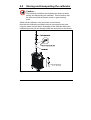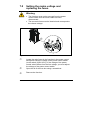
1
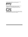
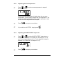
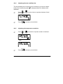
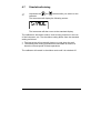
User Manual Temperature Calibrator MTC-140/320/650 A Copyright 2001 AMETEK DENMARK A/S About this manual…. • The structure of the manual This user manual is aimed at users who are familiar with Ametek calibrators, as well as those who are not. The manual is divided into 10 chapters which describe how to set up, operate, service and maintain the calibrator. The technical specifications are described and accessories may be ordered from the list of accessories. • Safety symbols This manual contains a number of safety symbols designed to draw your attention to instructions which must be followed when using the instrument, as well as any risks involved. Warning Events which may compromise the safe use of the instrument and result in considerable personal or material damage. Caution… Events which may compromise the safe use of the instrument and result in slight personal or material damage. Note… Special situations which demand the user’s attention. 2 26-07-2004 105337 02 List of contents 1.0 2.0 3.0 Introduction ..............................................................................4 Safety instructions ...................................................................6 Setting up the calibrator ........................................................10 3.1 3.2 3.3 3.4 4.0 Receipt of the calibrator.............................................................. 10 Preparing the calibrator .............................................................. 12 Choice of insertion tube .............................................................. 13 Inserting the sensor .................................................................... 14 Operating the calibrator.........................................................17 4.1 4.2 4.3 4.4 4.5 4.6 Keyboard, display and connections............................................ 17 Starting the calibrator.................................................................. 20 Selecting the set-temperature .................................................... 20 Using the SWITCH TEST ........................................................... 22 Using the AUTO STEP ............................................................... 26 Using the MENU ......................................................................... 29 4.6.1 Adjusting the temperature unit ....................................... 30 4.6.2 Adjusting the max-temperature ...................................... 31 4.6.3 Adjusting the SWITCH TEST slope rate ........................ 31 4.6.4 Adjusting the extra stability time..................................... 32 4.6.5 Adjusting the temperature resolution ............................. 32 4.7 Simulation/training ...................................................................... 33 5.0 6.0 7.0 Storing and transporting the calibrator ...............................34 Errors.......................................................................................36 Setting the mains voltage and replacing the fuses............38 7.1 Returning the calibrator for service............................................. 39 8.0 Maintenance............................................................................41 8.1 Cleaning...................................................................................... 41 8.2 Adjusting and calibrating the instrument..................................... 42 8.2.1 Adjusting the calibration date ......................................... 44 8.2.2 Calibrating/adjusting the instrument............................... 45 9.0 Technical specifications........................................................49 10.0 List of accessories .................................................................55 105337 02 26-07-2004 3 1.0 Introduction Congratulations on your new Ametek JF Instruments MTC-Calibrator! With the Ametek JF Instruments calibrator, you have chosen an extremely effective instrument which we hope will live up to all your expectations. Over the past many years, we have acquired extensive knowledge of industrial temperature calibration. This expertise is reflected in our products which are all designed for daily use in an industrial environment. Please note that we would be very interested in hearing from you if you have any ideas or suggestions for changes to our products. This user manual applies to the following instruments: • • • ) MTC-140 A (with RS232) MTC-320 A (with RS232) MTC-650 A (with RS232) ISO-9001 certified Ametek Denmark A/S was awarded the ISO-9001 certificate in September 1994 by BVQI - Bureau Veritas Quality International. 4 26-07-2004 105337 02 ) CE-label Your new calibrator bears the CE label and conforms to the EMC directive and the Lowvoltage Directive. ) Technical assistance Please contact the dealer from whom you acquired the instrument if you require technical assistance. ) Guarantee According to current terms of sale and delivery. This guarantee only covers defects in manufacture and becomes void if the instrument has been subject to unauthorised intervention and/or misuse. 105337 02 26-07-2004 5 2.0 Safety instructions Read this manual carefully before using the instrument! Please follow the instructions and procedures described in this manual. They are designed to allow you to get the most out of your calibrator and avoid any personal injuries and/or damage to the instrument. Warning…… About the use: • • • • • • The calibrator must not be used for any purposes other than those described in this manual. The calibrator is designed for interior use only and should not be used in risk-prone areas, where vapour or gas leaks, etc. may constitute an explosives hazard. The calibrator must be kept clear within an area of 20 cm on all sides and 1 metre above the calibrator. Never use heat transfer fluids such as silicone, oil, paste, etc. These fluids may penetrate the calibrator and cause damage or create poisonous fumes. The calibrator must be switched off before any attempt to service the instrument is made. When cleaning the well, REMEMBER, wear goggles when using compressed air! About the frontpanel: • • 6 The connectors, on the front panel of the calibrator, must NEVER be connected to a voltage source. Thermostats must not be connected to any other voltage source during a test. 26-07-2004 105337 02 About insertion tubes and insulation plugs: • Never leave hot insertion tubes which have been removed from the calibrator unsupervised – they may constitute a fire hazard. If you intend to store the calibrator in the aluminium carrying case after use, you must ensure that the instrument has cooled to a temperature below 100°C/212°F before placing it in the carrying case. About the fuses: • The fuse box must not be removed from the power control switch until the mains cable has been disconnected. • The two main fuses must be identical and correspond to the chosen voltage. 105337 02 26-07-2004 7 Caution – Hot surface This symbol is engraved in the grid plate. • Do not touch the grid plate, the well or the insertion tube as the calibrator is heating up – they may be very hot. • Do not touch the tip of the sensor when it is removed from the insertion tube/well – it may be very hot. • Do not touch the handle of the calibrator during use – it may be very hot. • Over 100°C/212°F If the calibrator has been heated up to temperatures above 100°C/212°F, you must wait until the instrument reaches a temperature below 100°C/212°F before you switch it off. Below 0°C/32°F (applies only to the MTC-140 A model) If the calibrator has reached a temperature below 0°C/32°F, ice crystals may form on the insertion tube and the well. This, in turn, may cause verdigris to form on the material. To prevent this from happening, simply heat up the calibrator to 50°C/122°F. 8 26-07-2004 105337 02 Caution… About the use: • Do not use the instrument if the ventilator is out of order. • Before cleaning the calibrator, you must switch it off, allow it to cool down and remove all cables. About the well, insertion tube and grid plate: • The well and the insertion tube must be clean before use. • Scratches and other damage to the insertion tubes should be avoided by storing the insertion tubes carefully when not in use. • The insertion tube must never be forced into the well. The well could be damaged as a result, and the insertion tube may get stuck. • The insertion tube must always be removed from the calibrator after use. The humidity in the air may cause verdigris to form on the insertion tube inside the instrument. There is a risk that the insertion tube may become stuck if this is allowed to happen. • If the calibrator is to be transported, the insertion tube must be removed to avoid damage to the instrument. Note… The product liability only applies if the instrument is subject to a manufacturing defect. This liability becomes void if the user fails to follow the maintenance instructions set out in this manual or uses unauthorised spare parts. 105337 02 26-07-2004 9 3.0 Setting up the calibrator 3.1 Receipt of the calibrator The calibrator is supplied in an aluminium carrying case. When you receive the instrument… • Carefully unpack and check the calibrator and the accessories. • Check the parts off against the list shown below. If any of the parts are missing or damaged, please contact the dealer who sold the calibrator. IBR CAL ATIO N INS TS MEN TRU You should receive: • 1 calibrator • 1 mains cable • 1 set of test cables (1 black, 1 red) • 3 pcs. insulation plugs for 6, 10, 13 mm sensors (MTC-140 A only) 10 26-07-2004 105337 02 • 1 insertion tube (user specified) • 1 tool for insertion tube • 1 traceable certificate • 1 user manual • 1 RS 232 serial cable • 1 CD-ROM containing software package “JofraCal”. When reordering, please specify the parts number found in the list of accessories, section 10.0. 105337 02 26-07-2004 11 3.2 Preparing the calibrator Warning • The calibrator must not be used in areas prone to explosives hazards. • The calibrator must be kept clear within an area of 20 cm on all sides and 1 metre above the calibrator. Note… The instrument must not be exposed to draughts. Fig. 1 When setting up the calibrator, you must… 12 place the calibrator on an even horizontal surface in the spot you intend to use it. 26-07-2004 105337 02 Caution… Do not use the instrument if the ventilator is out of order. ensure a free supply of air to the ventilator located at the bottom of the instrument. check the voltage of the power control switch (on/off switch (230V/115V)). If the voltage of the power control switch differs from the line voltage, you must adjust the voltage of the power control switch as follows (see Fig. 1): A. Open the fuse box lid using a screwdriver. B. Take out the fuse box. C. Remove both fuses and insertion tube two new fuses. These must be identical and should correspond to the line voltage. See section 10.0. B. Turn the fuse box 180° and slide it into place. check that the earth connection for the instrument is present and attach the cable. g select an insertion tube with the correct bore diameter. See section 3.3 for information on how to select insertion tubes. The calibrator is now ready for use. 3.3 Choice of insertion tube Insertion tubes are selected on the basis of the diameter of the sensor to be calibrated. Use the table for insertion tubes in section 10.0 to find the correct parts number. Alternatively, you may order an undrilled insertion tube and drill the required hole yourself. The finished dimension should be as follows: • Sensor diameter +0.2 +0.05/-0 mm. 105337 02 26-07-2004 13 3.4 Inserting the sensor Before inserting the sensor and switching on the calibrator, please note the following important warning: Warning • Never use heat transfer fluids such as silicone, oil, paste, etc. These fluids may penetrate the calibrator and cause damage or create poisonous fumes. Caution… • • • The well and the insertion tube must be clean before use. Scratches and other damage to the insertion tubes should be avoided by storing the insertion tubes carefully when not in use. The insertion tube must never be forced into the well. The well could be damaged as a result, and the insertion tube may get stuck. • Caution – Hot surface • • • 14 Do not touch the grid plate, the well or the insertion tube as the calibrator is heating up – they may be very hot. Do not touch the tip of the sensor when it is removed from the insertion tube/well – it may be very hot. Do not touch the handle of the calibrator during use – it may be very hot. 26-07-2004 105337 02 Insert the sensor as shown in Fig. 2. Sensor under test Insertion tube Thermal protection shield Fig. 2 In order to spare the sensor and its connections it is recommended to use a heat protection shield (104216) at high temperatures. For MTC-140 A only. Check that the insulation plug fits the diameter of the sensor. Otherwise replace it. 105337 02 26-07-2004 15 If the design of the sensor permits it, you are advised to use an insulation tube and insulation as shown in Fig. 3. Fig. 3 16 26-07-2004 105337 02 4.0 Operating the calibrator 4.1 Keyboard, display and connections Keyboard CALIBRATION INSTRUMENTS SWITCH AUTO ESC TEST STEP MENU Fig. 4 Pos. Description LCD. AUTO STEP button used to activate AUTO STEP. The function is used to switch between a series of settemperatures automatically. ESC/MENU button used as Escape key or to activate the menu system (hold button down for min. 2 seconds). ENTER button used to accept chosen options. SWITCH TEST button used to activate SWITCH TEST. The function automatically detects the opening/closing temperatures for thermostats. DOWN ARROW button used to adjust temperature values (value decreases) and to select menu options. 105337 02 26-07-2004 17 UP ARROW button used to adjust temperature values (value increases) and to select menu options. Display Fig. 5 Pos. Description CHECKMARK displayed when the calibrator is stable. SWITCH TEST input open. SWITCH TEST input closed. AUTO STEP symbol used to indicate that the function is active (symbol flashes repeatedly). Used to display set-temperatures, time-until-stable and parameter values in the menu system. Minute time unit for bottom display. Fahrenheit temperature unit for bottom display. Fahrenheit temperature unit for top display. 18 Celsius temperature unit for bottom display. 26-07-2004 105337 02 Celsius temperature unit for top display. Used to display Read-temperature and parameters in the menu system. Connections Warning • The connectors, pos. 2 on the front panel, must NEVER be connected to a voltage source. • Thermostats must not be connected to any other voltage source during a test. All connections are located on the front panel. - + Switch Test RS232 Fuse 230V 5AF/115V 10AF 115V Fig. 6 Pos. Description Power control switch with connection for cable and on/off switch. Also contains the main fuse. See section 7.0 for information on how to change the fuses and setting the mains voltage. Connection for thermostat test. 105337 02 26-07-2004 19 Connection for RS232 cable. Note that all PC-equipment, which are connected to the calibrator must observe the directive IEC950. 4.2 Starting the calibrator Switch the calibrator on using the power control switch (pos. 1 in Fig. 6). The instrument is initialised and the last calibration date is displayed: The calibration date will be displayed for approx. 2 seconds. The initialisation process has been completed and the calibrator is ready for use. All settings are stored when the calibrator is switched off. When the instrument is switched back on again, the status will be the same as when it was switched off. 4.3 Selecting the set-temperature Press or to adjust the set-temperature. The current selection flashes in the bottom display: °C °C The starting point is the last chosen set-temperature (even if the instrument has been switched off). 20 26-07-2004 105337 02 Press to accept the change or to cancel. The calibrator will now heat up/cool down. The top display continuously shows the read-temperature. The bottom display shows either the set-temperature or the estimated time in whole minutes until the calibrator will be stable: °C min When the calibrator is stable the display will show the checkmark symbol. The instrument will emit an audible alarm and the estimated time until stable will be replaced by the settemperature: °C °C 105337 02 26-07-2004 21 4.4 Using the SWITCH TEST SWITCH TEST automatically locates the switch temperature of a thermostat. You must enter a temperature range Tmin - Tmax , within which the switch temperature is expected to be found. You must also specify the slope rate to be used during the test in SETUP (the smaller the value, the more accurate the results of the test and the longer the test will take). The function can be illustrated using the following example: Fig. 7 Press . The symbols for SWITCH TEST will flash to indicate that the function is active. 22 The function can be cancelled at any time by pressing 26-07-2004 105337 . 02 Press or to select the required Tmin: °C Press Press to accept your selection. or to select the required Tmax: °C Press to accept your selection. The calibrator will now start working towards the Tmin: °C °C Once the Tmin has been reached and the calibrator is stable, the instrument will emit an audible alarm and display the status for one second: °C °C 105337 02 26-07-2004 23 The calibrator will now start working towards the Tmax using the slope rate selected in SETUP. The flashing SWITCH TEST symbol indicates the current status: °C °C The instrument will check for changes in the SWITCH TEST. If no change has been detected by the time Tmax is reached, the instrument will register an ERROR. The calibrator will stabilise at this temperature, and then work towards the Tmin using the slope rate selected in SETUP. The flashing SWITCH TEST symbol indicates the current status: °C °C The instrument will check for changes in the SWITCH TEST input once again. If no change has been detected by the time the Tmin has been reached, the instrument will register an ERROR. The results of the test will be displayed as 3 values: an “Open” temperature, a “Close” temperature and a “Hyste” hysteresis temperature (the difference between the two temperatures). The open temperature is shown first: °C Press to display the close temperature: °C 24 26-07-2004 105337 02 Press to display the hysteresis temperature: °C If a temperature has not been found, the instrument will display an “Error” (the “Hyste” temperature will also be shown as an “Error”): or to end the SWITCH TEST. The Press instrument will store the Tmin and Tmax until the next time the SWITCH TEST is activated. Note… you can activate temporary results. 105337 02 or during the test to display the 26-07-2004 25 4.5 Using the AUTO STEP AUTO STEP is used to step automatically between a range of different calibration temperatures. This is useful when calibrating sensors in places which are hard to reach, and when calibrating sensors for which the output is displayed in a different location. The function can be illustrated using the following example: Fig. 8 Press . The symbol for AUTO STEP flashes to indicate that the function is active. 26 The function can be cancelled at any time by pressing 26-07-2004 105337 02 or to select the required number of steps Press (minimum 2 steps, maximum 9 steps): Press Press step 1: to accept your selection. or to select the required set-temperature for °C Press to accept your selection. Repeat the above procedure for all temperature steps. to accept your choices once you have adjusted Press the last temperature step. Press or to set the amount of extra time you wish the calibrator to remain at every step: min Press 105337 02 to accept your selection. 26-07-2004 27 The following will be displayed for one second to indicate that the calibrator is ready to work towards the set-temperature: °C The calibrator will now work towards the given set-temperature. An audible alarm will be emitted once the calibrator is stable. The calibrator will wait the specified amount of extra time. The instrument indicates this by counting down the amount of time remaining: °C min The calibrator will then go to the next step. The procedure is the same as for the first step. This process will be repeated until the last step has been executed and the function has been completed. 28 26-07-2004 105337 02 4.6 Using the MENU Hold down Press Press or parameters: for more than approx. 2 seconds: to select SETUP. to switch between the adjustable ⇑⇓ ⇑⇓ ⇑⇓ ⇑⇓ 105337 02 26-07-2004 29 If you wish to exit SETUP, simply press The instrument will ignore all changes if you press adjusting any of the parameters. Press 4.6.1 Adjusting the temperature unit Press . when to adjust the parameter. or to switch between °C and °F: °C - and °F 30 Press to accept your selection. 26-07-2004 105337 02 4.6.2 Adjusting the max-temperature or Press 0.1°C or 0.1°F: to set the max-temperature in steps of °C If the current set-temperature is higher than the new maxtemperature, you will need to adjust the set-temperature. The instrument will immediately begin to cool (if required) as soon as the new max-temperature is accepted. to accept your selection. Press If you wish to exit SETUP, simply press 4.6.3 Adjusting the SWITCH TEST slope rate Press or to set the SWITCH TEST slope rate to a temperature between 0.1°C and 9.9°C in steps of 0.1°C (if your chosen temperature unit is °F, the range will change to between 0.1°F and 9.9°F in steps of 0.1°F): . °C Press 105337 02 to accept your selection. 26-07-2004 31 4.6.4 Adjusting the extra stability time The extra stability time is the amount of extra time you wish to elapse before the checkmark symbol is displayed after the calibrator has stabilised. Press or 20 minutes: to set the time to anywhere between 0 and min to accept your selection. Press 4.6.5 Adjusting the temperature resolution Press or to select the required number of decimals: °C - and °C 32 Press to accept your selection. 26-07-2004 105337 02 4.7 Simulation/training Hold down the calibrator. and buttons while you switch on the The instrument will display the following screen: The instrument will then revert to the standard display. The calibrator’s simulation mode is used to train personnel in the use of the instrument, etc. The simulation setting differs from the standard setting as follows: • The instrument will not actually heat up or cool down the well. • The heating and cooling processes are simulated at around 10 times the normal speed of these operations. The calibrator will remain in simulation mode until it is switched off. 105337 02 26-07-2004 33 5.0 Storing and transporting the calibrator Caution… The following guidelines should always be observed when storing and transporting the calibrator. This will ensure that the instrument and the sensor remain in good working order. Switch off the calibrator using the power control switch. Note that the calibration procedure may be interrupted at any time using the power control switch. Switching off the calibrator during the calibration process will not damage either the instrument or the sensor. CA LI B RA T IO N IN ST RU ME NT S Fig. 9 34 26-07-2004 105337 02 The following routine must be observed before the insertion tube is removed and the instrument switched off: Over 100°C/212°F If the calibrator has been heated up to temperatures above 100°C/212°F, you must wait until the instrument reaches a temperature below 100°C/212°F before you switch it off. Below 0°C/32°F (applies only to the MTC-140 A model) If the calibrator has reached a temperature below 0°C/32°F, ice crystals may form on the insertion tube and the well. This, in turn, may cause verdigris to form on the material. To prevent this from happening, simply heat up the calibrator to 50°C/122°F. Remove the insertion tube from the calibrator using the tool for insertion tube supplied with the instrument as shown in Fig. 9. Caution… • The insertion tube must always be removed from the calibrator after use. The humidity in the air may cause verdigris to form on the insertion tube inside the instrument. There is a risk that the insertion tube may become stuck if this is allowed to happen. • If the calibrator is to be transported, the insertion tube must be removed to avoid damage to the instrument. Warning Never leave hot insertion tubes which have been removed from the calibrator unsupervised – they may constitute a fire hazard. If you intend to store the calibrator in the aluminium carrying case after use, you must ensure that the instrument has cooled to a temperature below 100°C/212°F before placing it in the carrying case. 105337 02 26-07-2004 35 6.0 Errors Warning The calibrator must be switched off before any attempt to service the instrument is made. Note… Ametek Denmark’s liability ceases if: • parts are replaced/repaired using spare parts which are not identical to those recommended by the manufacturer. • non-original parts are used in any way when operating the instrument. Ametek Denmark’s liability is restricted to errors which originated from the factory. If the calibrator detects an error during operation, the instrument will terminate all functions and display an error code: Likely cause: Solution: Likely cause: Solution: 36 Defective RTD-sensor or excessively high temperature measured by the instrument’s internal sensor. The calibrator should be returned to the manufacturer for service. The calibration coefficients have not been accepted. Try again. If the error message returns, the calibrator should be returned to the manufacturer for service. 26-07-2004 105337 02 Likely cause: Solution: An error has occurred in the control circuit. The calibrator should be returned to the manufacturer for service. Nothing happens when the power control switch (on/off switch) is pressed. Likely cause: Solution: 105337 02 There is no power to the calibrator. Check that the calibrator is correctly connected. Check the fuse. If there are no problems with the mains cable or the fuse, the calibrator should be returned to the manufacturer for service. 26-07-2004 37 7.0 Setting the mains voltage and replacing the fuses Warning • The fuse box must not be removed from the power control switch until the mains cable has been disconnected. • The two main fuses must be identical and correspond to the chosen voltage. Fig. 10 Locate the main fuses in the fuse box in the power control switch and check the voltage of the power control switch (on/off switch (230V/115V)). If the voltage of the power control switch differs from the line voltage, you must adjust the voltage of the power control switch. Open the lid of the fuse box using a screwdriver. Remove the fuse box. 38 26-07-2004 105337 02 Remove both fuses and insert two new fuses. These must be identical and should correspond to the line voltage. • MTC-140: 115V, 2AT = 105014 / 230V, 1AT = 105007 • MTC-320/650: 115V, 10AF = 60B302 / 230V, 5AF = 60B301 If the fuses blow immediately after you have replaced them, the calibrator should be returned to the manufacturer for service. Slide the fuse box into place with the correct voltage turning upwards. 7.1 Returning the calibrator for service When returning the calibrator to the manufacturer for service, please enclose a fully completed service information form. Simply copy the form on the following page and fill in the required information. The calibrator should be returned in the aluminium carrying case. Furthermore please follow the guidelines for transportation described in chapter 5.0 – Storing and transporting the calibrator. 105337 02 26-07-2004 39 Service info Customer data: Date: Customer name and address:___________________________________________ Attention and Dept.:___________________________________________________ Fax no./Phone no.:____________________________________________________ Your order no.:_______________________________________________________ Delivery address:_____________________________________________________ Distributor name:_____________________________________________________ Instrument data: Model and Serial no.:__________________________________________________ Warranty claimed Yes:____ No:_____ Original invoice no.:_________________ ___________________________________________________________________ Temp. calibration Sensor input Service request: This instrument is sent for (please tick off): ___ Calibration as left ___ Check ___ Calibration as found and as left ___ Service ___ Accredited calibration as left ___ Repair ___ Accredited calibration as found and as left. ___________________________________________________________________ Diagnosis data/cause for return: Diagnosis/Fault description:_____________________________________________ ___________________________________________________________________ Special requests:_____________________________________________________ ___________________________________________________________________ Safety precautions: if the product has been exposed to any hazardous substances, it must be thoroughly decontaminated before it is returned to Ametek. Details of the hazardous substances and any precautions to be taken must be enclosed. 40 26-07-2004 105337 02 8.0 Maintenance 8.1 Cleaning Caution… Before cleaning the calibrator, you must switch it off, allow it to cool down and remove all cables. Users should/must carry out the following cleaning procedures as and when required: • The exterior of the instrument - Clean using water and a soft cloth. The cloth should be wrung out hard to avoid any water penetrating the calibrator and causing damage. When heavily soiled the exterior of the instrument and the keyboard can be wiped clean using isopropyl alcohol. • The insertion tube - Must always be clean and should be regularly wiped using a soft, dry cloth. You must ensure there are no textile fibres on the insertion tube when it is inserted in the well. The fibres may adhere to the well and damage it. • The well - Must always be clean. Dust and textile fibres should be removed from the well using e.g. compressed air. Warning REMEMBER! Wear goggles when using compressed air! 105337 02 26-07-2004 41 8.2 Adjusting and calibrating the instrument You are advised to return the calibrator to Ametek Denmark A/S or an accredited laboratory at least once a year for calibration and adjustment. Alternatively, you can calibrate/adjust the calibrator yourself. You will need a reference thermometer and a reference sensor with a traceable certificate. Please follow the instructions given below. Connect the calibrator to an external precision instrument (e.g. a DTI) as shown in Fig. 11: Fig. 11 Hold down the control switch. button while pressing the on/off power The instrument is now in adjustment/service mode. 42 26-07-2004 105337 02 Press or to toggle between the different options: ⇑⇓ ⇑⇓ ⇑⇓ Press to accept your selection. To exit the adjustment/service mode, switch the instrument off and on again using the power control switch. 105337 02 26-07-2004 43 8.2.1 Adjusting the calibration date Adjust the date by toggling through the available days, months and years. Begin by selecting the required day as shown below: Press 31. Press Press or to select the required month from JAN / FEB / MAR / APR / MAY / JUN / JUL / AUG / SEP / OCT / NOV / DEC. Press Press 44 or to select the required day in the interval 1- to accept your selection. to accept your selection. or to select a year between 2001–2025. 26-07-2004 105337 02 to accept your selection. The day will be Press adjusted if necessary to ensure the legality of the date. Finally, the day, month and year will flash: Press to accept the date. or press 8.2.2 Calibrating/adjusting the instrument to cancel the whole selection. The internal calibration/adjustment is a complex function which is divided into a number of different steps: The instrument will disclose the first calibration temperature by displaying the text “TEMP.1 XXX°C” for approx. 1 second: Calibration temperature for calibrators: MTC-140 A 105337 02 1. 2. 3. 4. 5. -15°C / 5°F 20°C / 68°F 60°C / 140°F 100°C / 212°F 140°C / 284°F 26-07-2004 45 MTC-320 A 1. 2. 3. 4. 5. 50°C / 122°F 120°C / 248°F 180°C / 356°F 250°C / 482°F 320°C / 608°F MTC-650 A 1. 2. 3. 4. 5. 50°C / 122°F 200°C / 392°F 350°C / 662°F 500°C / 932°F 650°C / 1202°F The instrument will now heat up/cool down to reach the first calibration temperature: °C °C Once the calibrator is stable, you need to enter the reference temperature found using the reference thermometer. The calibration temperature is suggested as a reference point: °C This procedure is repeated for TEMP.2, TEMP.3, TEMP.4 and TEMP.5. All five calibration temperatures and associated reference temperatures have now been entered. The instrument will now check whether the reference temperatures which have been entered are within the permitted tolerances. Permitted tolerances: • MTC-140 A, MTC-320 A: ±0,15°C / 0.27°F • MTC-650 A: ±0,25°C / 0.45°F 46 26-07-2004 105337 02 If the instrument detects excessive deviations for one or more steps, it will show a screen reading =ERR. in the top of the display. The text AdJ. will flash in the bottom of the display to indicate that an adjustment is required (accept by pressing ): If the calibrator is found to be within the permitted tolerances, the instrument will display the text =OK at the top of the display. The text Cont. will flash in the bottom of the display to indicate that you may continue without adjustments: Press to go back to a previous screen and press Press to repeat an adjustment step when it is shown on the display. Press when AdJ. is flashing to calculate a new set of Press coefficients. Next, repeat the entire calibration/adjustment procedure. 105337 02 to cancel the adjustment function. to toggle between AdJ. and Cont. on the display. 26-07-2004 47 If the new coefficients deviate by more than 4% from the standard values, the instrument will display an ERROR 2 in the display. The calculated coefficients will be ignored: to repeat the entire calibration/adjustment Press procedure. when Cont. is flashing to end the Press calibration/adjustment procedure and enter a new calibration date (see section 8.2.1). 48 26-07-2004 105337 02 9.0 Technical specifications The illustration below shows the setup which forms the basis for the technical specifications. Fig. 12 105337 02 26-07-2004 49 Pos. Description Calibrator Ø4.2 mm insertion tube Insulation 30 x 30 mm Insulation tube for Ø4 mm sensor Ø4 mm Pt 100 sensor with traceable certificate DTI 1000 reference precision thermometer with traceable certificate Thermal specifications 1 1 2 All specifications are given with an ambient temperature of 23°C/73.4°F ± 3°C/5.4°F Specified at 115V / 230V Specifications Model MTC-140 A Max. Temperature : 140°C / 284°F Min. Temperature : -30°C / -22°F @ ambient temperature 0°C / 32°F -17°C / 1°F @ ambient temperature 23°C / 73°F -2°C / 28°F @ ambient temperature 40°C / 104°F Display resolution : 0.1°C / 0.1°F Stability : ±0.05°C / ±0.09°F Accuracy : ±0.4°C / ±0.7°F Heating, 2 23°C to max. : 15 min. 50 26-07-2004 105337 02 Time to stability : 5 min. Cooling, max. to min. : 25 min. MTC-320 A Max. Temperature : 320°C / 608°F Min. Temperature : 33°C / 91°F @ ambient temperature 23°C / 73°F Display resolution : 0.1°C / 0.1°F Stability : ±0.1°C / ±0.18°F Accuracy : ±0.5°C / ±0.9°F Heating, 2 23°C to max. : 4 min. Time to stability : 8 min. Cooling, max. to min. : 29 min. MTC-650 A Max. Temperature : 650°C / 1202°F Min. Temperature : 33°C / 91°F @ ambient temperature 23°C / 73°F Display resolution : 0.1°C / 0.1°F Stability : ±0.1°C / ±0.18°F Accuracy : ±0.9°C / ±1.62°F Heating, 2 23°C to max. : 10 min. Time to stability : 8 min. Cooling, max. to min. : 44 min. 105337 02 26-07-2004 51 Electrical specifications Specifications Model MTC-140 A Power supply [VAC], 115VAC, 45-65Hz 230VAC, 45-65Hz : : 90-127 180-254 Power consumption, [VA] : 150 Test voltage, 5 : switch test [V] MTC-320 A Power supply [VAC], 115VAC, 45-65Hz 230VAC, 45-65Hz : : 90-127 180-254 Power consumption, [VA] : 1150 Test voltage, 5 : switch test [V] MTC-650 A Power supply [VAC], 115VAC, 45-65Hz 230VAC, 45-65Hz : : 90-127 180-254 Power consumption, [VA] : 1150 Test voltage, 5 : switch test [V] 52 26-07-2004 105337 02 Mechanical specifications Specifications Model MTC-140 A Weight : 6.5 Kg. / 14.3 Lbs. Dimensions HxWxL : 325 x 139 x 241 mm / 12.80 x 5.47 x 9.49 inch Operating temp. : 0 - 40°C / 32 - 104°F Storage temp. : -20 - 50°C / -4 - 122°F Humidity range : 0-90% Rh Protection class : IP10 MTC-320 A Weight : 5.0 Kg. / 11.0 Lbs. Dimensions HxWxL : 325 x 139 x 241 mm / 12.80 x 5.47 x 9.49 inch. Operating temp. : 0 - 40°C / 32 - 104°F Storage temp. : -20 - 50°C / -4 - 122°F Humidity range : 0-90% Rh Protection class : IP10 MTC-650 A Weight 105337 02 : 6.4 Kg. / 14.1 Lbs. 26-07-2004 53 Dimensions HxWxL : 325 x 139 x 241 mm / 12.80 x 5.47 x 9.49 inch. Operating temp. : 0 - 40°C / 32 - 104°F Storage temp. : -20 - 50°C / -4 - 122°F Humidity range : 0-90% Rh Protection class : IP10 Additional data - directives observed EMC directives 89/336 / EEC EN61326 (1997) EN61326 / A1 (1998) EN61326 / corr. (2000) Low-voltage Directive 73/23 / EEC EN61010-1 (1993) EN61010-1 / A2 (1995) Approvals Approved by “Det Norske Veritas” DNV. 54 26-07-2004 105337 02 10.0 List of accessories All parts listed in the list of accessories can be obtained from the factory through our dealers. Please contact your dealer for assistance if you require parts which do not appear on the list. List of accessories Accessories Parts no. Fuse 115V, 10AF (MTC-320/650 A) Fuse 230V, 5AF (MTC-320/650 A) Fuse 115V, 2AT (MTC-140 A) Fuse 230V, 1AT (MTC-140 A) User manual Tool for insertion tube Heat protection shield Alu. carrying case, high Mains cable, 115V, US, type B Mains cable, 240V, UK, type C Mains cable, 220V, South Africa, type D Mains cable, 220V, Italy, type E Mains cable, 240V, Australia, type F Mains cable, 230V, Europe, type A Mains cable, 230V, Denmark, type G Mains cable, 220V, Switzerland, type H Mains cable, 230V, Israel, type I Insulation tube, 100 mm Insulation tube, 150 mm Insulation tube, 200 mm Insulation tube, 250 mm 60B302 60B301 105014 105007 105337 60F170 104216 123408 60F135 60F136 60F137 60F138 60F139 60F140 60F141 60F142 60F143 65-F100 65-F101 65-F102 65-F103 105337 02 26-07-2004 55 List of accessories Accessories Parts no. Insulation tube, 300 mm Insulation tube, 350 mm Insulation tube, 400 mm Insulation tube, 450 mm Insulation 30 x 30 mm Cleaning brush, 4 mm Cleaning brush, 6 mm Cleaning brush, 8 mm Set of insulation plugs (MTC-140 A only) Set of test cables RS232 serial cable JofraCal PC software Certificate, National 65-F104 65-F105 65-F106 65-F107 105173 122832 60F174 122822 123469 104203 105366 124915 99-C-T PARTS NO. FOR STANDARD INSERTION TUBES Sensor size undrilled 1/8” 3/16” 1/4” 5/16” 3/8” 7/16” 1/2” 9/16” 5/8” 11/16” 13/16” 3/4” 7/8” 56 MTC-140 A MTC-320 A MTC-650 A 60F448 60F450 60F452 60F454 60F456 60F458 60F460 60F462 60F464 60F466 - 100175 100176 100178 100180 100181 100184 100187 100189 60F344 100192 60F348 60F352 100193 60F354 100194 100195 100197 100199 100200 100203 100205 100207 60F408 100210 60F412 60F416 100211 60F418 26-07-2004 105337 02 PARTS NO. FOR STANDARD INSERTION TUBES Sensor size 3 mm 4 mm 5 mm 6 mm 7 mm 8 mm 9 mm 10 mm 11 mm 12 mm 13 mm 14 mm 15 mm 16 mm 18 mm 20 mm MTC-140 A MTC-320 A MTC-650 A 123428 60F451 123429 60F453 123430 105185 105186 105187 123431 123432 123433 - 123436 100177 123437 100179 123438 100182 100183 100185 100188 100186 60F339 100190 100191 123439 123440 123441 123444 100196 123445 100198 122516 100201 100202 105188 100204 100206 105189 100208 100209 123446 122517 122518 PART NO. FOR STANDARD INSERTION TUBES – MULTI-HOLE Description MTC-140 A MTC-320 A MTC-650 A Metric Type 1 123479 123475 123476 Inch Type 2 123480 123477 123478 Note: All multi-hole insertion tubes are delivered with a matching insulation plug (MTC-140 only). 105337 02 26-07-2004 57