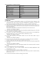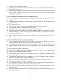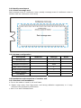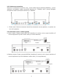
1
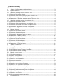
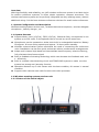
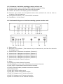
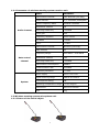
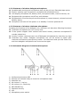
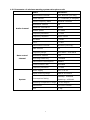
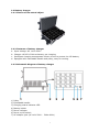
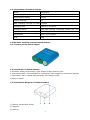
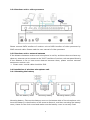
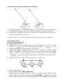
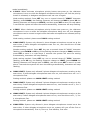
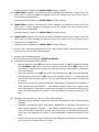
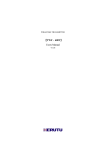
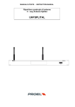
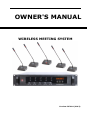
OWNER'S MANUAL WIRELESS MEETING SYSTEM Version: REV1.0 (2013) [Table of Contents] Overview 1. System Configuration and description-----------------------------------------------2 1.1 System features-----------------------------------------------------------------------2 1.2 Wireless meeting system receiver unit ----------------------------------------------2 1.2.1 Picture of the actual object -----------------------------------------------------------2 1.2.2 Features of wireless meeting system receiver unit ----------------------------------3 1.2.3 Schematic diagram of wireless meeting system receiver unit -----------------------3 1.2.4 Parameter of wireless meeting system receiver unit---------------------------------4 1.3 Wireless meeting system microphone unit-------------------------------------------4 1.3.1 Picture of the actual object -----------------------------------------------------------4 1.3.2 Features of wireless delegate microphone unit --------------------------------------5 1.3.3 Features of wireless chairman microphone unit -- ----------------------------------5 1.3.4 Schematic diagram of wireless microphone -----------------------------------------5 1.3.5 Parameter of Parameter of wireless microphone-------- ----------------------------6 1.4 Battery charger -----------------------------------------------------------------------7 1.4.1 Picture of the actual object -----------------------------------------------------------7 1.4.2 Features of battery charge------------------------------------------------------------7 1.4.3 Schematic diagram of battery charge------------------------------------------------7 1.4.4 Parameter of battery charge ---------------------------------------------------------8 1.5 Wireless meeting system Lithium battery ------------------------------------------8 1.5.1 Picture of the actual object------------------------------------------------------------8 1.5.2 Features of Lithium battery-----------------------------------------------------------8 1.5.3 Schematic diagram of Lithium battery------------------------------------------------8 1.5.4 Parameter of Lithium battery---------------------------------------------------------9 2. System installation-------------------------------------------------------------------9 2.1 Warning-------------------------------------------------------------------------------9 2.1.1 CAUTION on handling of the microphone unit---------------------------------------10 2.1.2 CAUTION on battery charger handling----------------------------------------------10 2.1.3 CAUTION on battery handing--------------------------------------------------------10 2.2 Identify room layout-----------------------------------------------------------------11 2.2.1 Check coverage area-----------------------------------------------------------------11 2.2.2 System configuration----------------------------------------------------------------11 2.3 Installation and connection of receiver unit-----------------------------------------11 2.3.1 Receiver unit installation------------------------------------------------------------11 2.3.2 Antenna connection------------------------------------------------------------------12 2.3.3 Receiver unit to sound system------------------------------------------------------12 2.3.4 Receiver unit to video processor-----------------------------------------------------13 2.3.5 Receiver unit to external antenna---------------------------------------------------13 2.4 Installation of wireless microphone unit--------------------------------------------13 2.4.1 Mounting and dismounting the battery----------------------------------------------13 2.4.2 Mounting and dismounting the microphone-----------------------------------------14 2.5 System setting-----------------------------------------------------------------------14 2.5.1 Receiver unit setting-----------------------------------------------------------------14 2.5.2 Microphone setting and operation---------------------------------------------------18 3. Troubleshooting----------------------------------------------------------------------19 1 Overview With high flexibility and reliability, our UHF wireless conference system is an ideal choice for mobile conference systems. It offers simple operation, compact structures. The wireless conference system can be perfectly integrated into any meeting rooms, without additional wiring. It’s the best wireless conference solutions for small-scale conferences. 1. System Configuration and description Wireless meeting system receiver unit , wireless chairman microphone , wireless delegate microphone , battery charger , etc. 1.1 System features Support Mode: Limit (1/2/3/4), FIFO (1/2/3/4), Chairman Only, microphones in one system up to 256 units, 5 microphones can be turned on at the same time. Microphones can be operated on either their built-in rechargeable batteries. Battery life approx. 8 hours during speech and approx. 30 hours when standby. Wireless communication system eliminates the need of connecting the conference units. Installation can be done quick and smart without cumbersome arrangements. Adopt multi-channel high band and intermediate band frequency selective filtering, fully eliminate interference signal Built-in feedback eliminating technology which can decrease the feedback and nois e effectively Built-in multiple noise detecting circuit and TONE-LOCK system to make sure the system has strong anti-jamming function Operation distance up to 100 meters with the best condition, 60 meters in normal condition. Support video camera auto-track function with video processor 1.2 Wireless meeting system receiver unit 1.2.1 Picture of the actual object 2 1.2.2 Features of wireless meeting system receiver unit Support Mode: Limit (1/2/3/4), FIFO (1/2/3/4), Chairman Only Support video camera auto-track with video processor 160x32 dot matrix LCD display system information Receiver can control the microphone status when powered off, such as clear or shutting off all microphones. Designed accordance to UL, CE and RTTE standards Installation: 19-inch frame 1.2.3 Schematic diagram of wireless meeting system receiver unit 1) Power switch 2) RF/Audio Level indicator ( First channel only for chairman mic, the last four channels for delegate mic) 3) Volume knob of chairman microphone (Channel 1) 4) Volume knob of delegate microphone (Channel 2) 5) Volume knob of delegate microphone (Channel 3) 6) Volume knob of delegate microphone (Channel 4) 7) Volume knob of delegate microphone (Channel 5) 8) Setting key/check channel frequency 9) Menu 10) Setting key/check channel frequency 11) LCD (Display current mode, frequency point of each channel) 12) ANT DATA: System data control antenna interface 13) DATA: External video processor connection interface 14) DC Power input 15) MIX OUT: Mixed audio output 16) MIX BAL: Mixed audio balance output 17) ANT B: Delegate mic RF antenna interface 18) ANT B: Delegate mic RF antenna interface 19) ANT A: Chairman mic RF antenna interface 3 1.2.4 Parameter of wireless meeting system receiver unit Items Parameter Transmission method UHF Wireless (one way) Audio channel 5 (1 chairman,4 delegate) Carrier frequency band 500MHz~950MHz Modulation method FM Receiving sensitivity -100dBM Audio gain ≤20 Frequency response 50Hz-15KHz S/N Ratio >85dB T.H.D. <0.8% Transmission method Wireless (two-way) Data channel 16 Frequency Range 422.4MHz ~ 438.4MHz Data control Modulation method FSK channel Receiving sensitivity -100dBM Transmission consumption ≤6dBm Communication rate 100KBPS Frequency deviation <0.002 Power supply DC12~15V ≤1A Signal covering range Radius 60 meters Consumption Rating 7W Operating temperature range -10-40 degree Dimensions 485×355×85mm N.W 7kg Audio channel System 1.3 Wireless meeting system microphone unit 1.3.1 Picture of the actual object 4 1.3.2 Features of wireless delegate microphone Portable table moving and microphone pipe can be pull out. Extended pipe option. Electric capacity type microphone, equipped with windshield cover LCD display microphone ID, battery level, microphone state, control channel, etc. Equipped with microphone on/off key and indicator. Equipped with 3 function keys to set microphone id, control channel, volume level and battery status. Microphone will shut off the power or in standby if receiver powered off. 1.3.3 Features of wireless chairman microphone Including the functions of the delegate unit, chairman unit has other following functions: Chairman microphone can turn on any time. If the system support video camera auto-track function, chairman microphone ID number should be 1 Priority function: chairman can turn off delegate microphones by clear key any time Chairman only mode: Delegate microphone can not be turned on again after chairman microphone press priority button. The chairman need quit this mode first, and then delegate microphone can be turned on again 1.3.4 Schematic diagram of wireless microphone 1) 2) 3) 4) 5) 6) 7) 8) 9) Unidirectional electret MIC Annular red indicator lamp to show the microphone state. Mute/Set key Mic volume +/ up key Mic volume up -/down key MIC ON/OFF key Chairman Priority LCD Microphone power switch 5 1.3.5 Parameter of wireless meeting system microphone unit Items Parameter Transmission method UHF Wireless (one way) Audio channel 5 ( 1 chairman, 4 delegate) Carrier frequency band 500MHz~950MHz Modulation method FM Maximum modulation 60KHz Radiant power ≤+9dBm Frequency deviation <0.002 Frequency response 50Hz-15KHz S/N Ratio >85dB T.H.D. <0.8% Transmission method Wireless (two-way) Data channel 16 Frequency Range 422.4MHz ~ 438.4MHz Data control Modulation method FSK channel Receiving sensitivity -100dBM Transmission consumption ≤6dBm Communication rate 100KBPS Frequency deviation <0.002 Power supply DC3.7~4.5V Signal covering range Radius 60 meters Audio channel System Consumption Rating Standby: ≤360mW Speaking: ≤630mW Operating temperature range -10-40 degree Dimensions 170×58×120mm N.W 0.7kg 6 1.4 Battery charger 1.4.1 Picture of the actual object 1.4.2 Features of battery charger a. Input Voltage: AC 110V~220V b. Charges 16 PCS of lithium battery per charging c. Intelligent charging management electro circuit to protect the LIP battery d. Equipped with extendable handle and pulley, easy for moving. 1.4.3 Schematic diagram of battery charger 1) 2) 3) 4) 5) 6) 7) Pulley Extendable handle Charging status indicator LED Battery holder Power indicator Power on/off switch AC adapter jack (AC110V-220V~ 50Hz-60Hz) 7 1.4.4 Parameter of battery charger Items Parameter Power supply 110V-240V/50Hz~60Hz Consumption Rating 200W Charge quantity 16 MAX charging current of each 700mA Charging time About 8~10 hours Charging status Red LED flashing –Charging, Green LED –Full Operating temperature range 0-40 degree Dimensions 620×370×175mm N.W 9kg 1.5 Wireless meeting system Lithium battery 1.5.1 Picture of the actual object 1.5.2 Features of Lithium battery a. Excellent safety performance, light weight & High capacity ratio. b. Improved safety: more resistant to overcharge; less change for electrolyte leakage. c. The battery life is usually approximately 300 charge cycles. d. Easy to install 1.5.3 Schematic diagram of Lithium battery 1) Battery detach/lock button 2) Negative 3) Positive 8 1.5.4 Parameter of Lithium battery Items Parameter Rated voltage DC3.7V Discharge current <500mA Charging current <700mA Time of speaking >8 hours Time of standby >24 hours Charging voltage DC5V Dimensions 47×40×12mm N.W 54g 2. System installation 2.1 Warning This is a wireless communication system, use UHF band carrier frequency. We recommend that users consult local radio management committee to choose the appropriate and legally available frequency, in order to avoid RF interference If the units demonstrate any problems, such as abnormal sound, smoke, heat from or damage to power cables, disconnect the power plug from the outlet and contact your sales representative. If the power plug blades are distorted or discolored, do not use the unit (Receiver unit, Battery charger) Uncoil the power cables before use, Do not bundle the cables during use, or fie with nails. (Receiver unit, Battery charger) Do not pull on the cable. Hold the plug section and insert/remove it in a straight line, damaged cables may result in electric shock, malfunction, or fire. (Receiver unit, Battery charger) Do not place anything on the power cables. Do not route them under a rug or furniture. (Receiver unit, Battery charger) Do not cover the units with cloth or place them in locations with poor ventilation. Doing so traps heat, and may result in electric shock or fire If you do not use the units for long periods of time, disconnect the power plugs from the outlet (Receiver unit, Battery charger) Do not disassemble the units. Touching the inside of the units may result in electric shock Do not expose the units to any strong shock Do not expose the units to direct sunlight, heat from heating appliances, high temperatures, or dust Do not expose the units to high humidity or moisture Water that accidentally enters the inside of the units may result in electric shock, malfunction, or fire Do not touch the power cables or plugs with wet band 9 (Receiver unit, Battery charger) Main unit is a class I device. Be certain to connect to an AC outlet with a protective grounding connection Main unit can be separated from the AC receptacle by turning off the unit by the front power switch. In case of emergency, turn off this switch or unplug the power cable from the AC receptacle 2.1.1 CAUTION on handling of the microphone unit Do not grasp the microphone to lift or pull on the microphone unit: pick up the unit by its base Slowly bend and straighten the flexible part of the microphone. Do not bend it with excessive force Do not drop the unit If you do not use the unit for long periods of time, remove the battery The dedicated lithium-ion battery should be used Do not place any obstructions around the microphone units When the microphone units are too close together, high sound volume may cause acoustic feedback, In this case, increase the space between the conference units or turn down the volume After the battery has been removed and replaced, confirm that the power LED turns off 2.1.2 CAUTION on battery charger handling If the charging terminal is dirty, poor contact will prevent the battery from being charged properly. Periodically clean the charging terminals The battery charger may become hot during charging. Use it in a well-ventilated area After the battery is fully charged, turn off the battery charger or remove the batteries 2.1.3 CAUTION on battery handling The battery is dedicated to the microphone unit. Do not use it for other applications Use only the designated battery charger If the battery leaks and the liquid contacts your skin or clothing, immediately flush with clean water If the battery leaks and the liquid contacts your eyes, immediately wash thoroughly with clean water and seek medical assistance Do not throw the battery into fire or overheat it, Doing so may result in a fire Do not disassemble or modify the battery Do not short-circuit the + and – terminals with any metal or wire. Do not carry or store the battery with metal products such as a necklace. If you discover battery leaks, discoloration, distortion, or the other problems, do not use the battery Dispose of used batteries properly as industrial waste or contact our business office in your neighborhood 10 2.2 Identify room layout 2.2.1 Check coverage area Real coverage area of conference room (usually coverage area of conference room is smaller than the conference room area) 2.2.2 System configuration Description Model No. Max Qty Receiver Unit 1 Chairman Microphone 1 Delegate Microphone ≤255 Data Control Antenna 1 Audio Control Antenna 3 Marks Battery Charger LIP Battery 2.3 Installation and connection of receiver unit 2.3.1 Receiver unit installation a. Put on the table or install in 19 inch frame b. Please keep away from high-power and strong radiation equipments, or it may influence the equipment performance. c. Use it in a well-ventilated area 11 2.3.2 Antenna connection There are 4 antennas of receiver unit. 1 piece data control antenna (426MHz), 1 piece chairman microphone audio control/RF antenna (A: 750MHz) and 2 pieces delegate microphone audio control/RF antenna (B: 780MHz) Please note: Receiver antennas should be connected correct position, or system can not work properly. 2.3.3 Receiver unit to sound system a. Mono output: Please connect MIX OUT interface of receiver unit to input interface of sound equipment by Φ6.3 audio cable (for short distance) b. Balance output: Please connect MIX-BAL interface of receiver unit to input interface of sound equipment by XLR-M balance audio cable ( for long distance) 12 2.3.4 Receiver unit to video processor Please connect DATA interface of receiver unit to DATA interface of video processor by RJ45 network cable. Please read the user manual of video processor. 2.3.5 Receiver unit to external antenna If the distance between receiver and microphone is not far, and there does not have any obstruct, antenna can be connect to the “ANT” interface of receiver unit rear panel directly. If the distance is far or have some obstruct between them, please connect external antenna to receiver unit. Please note: coaxial cable should be 50Ω. 2.4 Installation of wireless microphone unit 2.4.1 Mounting the battery Take out battery cover Mounting battery Mounting battery cover Mounting battery: Take out the battery cover on the bottom side of the microphone unit; insert the battery in the direction of the arrow to fasten it, and then mounting the battery cover, Listen for the click sound and make sure the battery cover is securely fixed. 13 2.4.2 Mounting and dismounting the microphone a. Mounting microphone: Insert the microphone into the microphone mounting socket in a straight line, and then rotate the microphone clockwise to fasten it securely. b. Dismounting microphone: Rotate the microphone counterclockwise, then pull the microphone upward to dismounting * Please contact us if you need more detailed information during your installation. 2.5 System setting 2.5.1 Receiver unit setting a. POWER ON/POWER OFF POWER ON: Hold the “POWER” button on the left front panel of receiver till LCD display “ “ and then release it LCD will display “ “, after system self-detecting LCD will display “ “ POWER OFF: Hold the “POWER” button on the left front panel of receiver till LCD display “ “, receiver unit will powered off and all microphones in standby status when released the button. If still hold the button, LCD will display “ “, both receiver and microphones are powered off at the same time. a. System function key: There are 3 function keys on receiver unit DOWN SET UP b. System mode setting: System default mode: CFREE-4MAX-FIFO System support 10 modes setting by receiver unit (FIFO 1/2/3/4, LIMIT 1/2/3/4, CONLY, CFREE), user can set these mode by UP & DOWN key. System will save and keep the last setting mode in 3 seconds automatically or press SET key to save the 14 mode immediately. C.ONLY: When chairman microphone priority button was press on, the chairman microphone is turn on while the delegate microphone being turn off until the priority button is released, or delegate microphone can not turn on again. Mode setting method: Press SET key one or several times till “CFREE” character flashing, press DOWN, the flashing character will change to CONLY (press UP the flashing character will change to CFREE), and then press SET to save it or wait about 3 seconds the system will save the mode automatically, characters will stop flashing. C.FREE: When chairman microphone priority button was press on, the chairman microphone is turn on while the delegate microphone being turn off, but delegate microphone can be turned on again even chairman microphone not released priority button. Mode setting method: please see C.ONLY setting method 1MAX-LIMIT: System only allowed 1 piece delegate microphone turned on at the same time, if other delegate microphones want turn on, user should turn off that microphone first. Number setting method: Press SET key one or several times till “4MAX” character flashing, press DOWN or UP key till the flashing character change to 1MAX, and then press SET to save it or wait about 3 seconds the system will save the setting automatically, characters will stop flashing Mode setting method: Press SET key one or several times till “FIFO” character flashing, press UP key, the flashing character change to LIMIT (press DOWN the flashing character will change back to FIFO), and then press SET to save it or wait about 3 seconds the system will save the setting automatically, characters will stop flashing. 2MAX-LIMIT: System only allowed 2 pieces delegate microphones turned on at the same time, if other delegate microphones want turn on, user should turn off 1 or 2 microphones first. Setting method: please see 1MAX-LIMIT setting method 3MAX-LIMIT: System only allowed 3 pieces delegate microphones turned on at the same time, if other delegate microphones want turn on, user should turn off 1, 2 or 3 microphones first. Setting method: please see 1MAX-LIMIT setting method 4MAX-LIMIT: System only allowed 4 pieces delegate microphones turned on at the same time, if other delegate microphones want turn on, user should turn off 1, 2, 3 or 4 microphones first. Setting method: please see 1MAX-LIMIT setting method 1MAX-FIFO: System only allowed 1 piece delegate microphones turned on at the same time, if other delegate microphone turns on, system will turn off the first on microphone automatically. First in, first out, first indicate, first offer. 15 Setting method: please see 1MAX-LIMIT setting method 2MAX-FIFO: System only allowed 2 piece delegate microphones turned on at the same time, if other delegate microphone turns on, system will turn off the first on microphone automatically. Setting method: please see 1MAX-LIMIT setting method 3MAX-FIFO: System only allowed 3 piece delegate microphones turned on at the same time, if other delegate microphone turns on, system will turn off the first on microphone automatically. Setting method: please see 1MAX-LIMIT setting method 4MAX-FIFO: System only allowed 4 piece delegate microphones turned on at the same time, if other delegate microphone turns on, system will turn off the first on microphone automatically. Setting method: please see 1MAX-LIMIT setting method Please note: Chairman microphone is not limit in these mode, chairman microphone can be turned on and off independently. c. System audio channel setting System default audio channel: 40[05-35-65-95] Chairman microphone audio channel Manual setting: Press SET key one or several times till “40” character flashing, press DOWN or UP key to select the channel, and then press SET to save it or wait about 3 seconds the system will save the setting automatically, characters will stop flashing Auto-scan setting: Press SET key one or several times till “40” character flashing, and then press and hold the SET key till LCD display symbol ---, release the key, system will scan all audio channel (00-99) automatically and select the best one to save it. Chairman microphone audio description: Bandwidth of chairman microphone is 25M; default setting is 740MHz -- 764.75MHz (Please contact us or agent to get more information if user want choose other frequency for chairman microphone). There are 100 channels for option in this bandwidth, frequency interval is 250 KHz. Delegate microphone (D1, D2, D3, D4) audio channel Channel setting method: please see chairman microphone audio channel setting method. Delegate microphone audio description: Bandwidth of delegate microphone is 25M, default setting is 765MHz -- 789.75MHz (Please contact us or agent to get more information if user want choose other frequency for delegate microphone). There are 100 channels for option in this bandwidth, frequency interval is 250 KHz. Please note there are 4 audio channel of the delegate microphone in the system, so the channel number cannot be same. 16 d. System project setting Press SET key and turn on the receiver with POWER key at the same time, receiver LCD will display , there are 4 setting menu in this part. Receiver data (room) channel setting (Default channel is "ROOM 0"), there are 16 data (room) channel for option (0-1-2-3-4-5-6-7-8-9-A-B-C-D-E-F), user can select the channel by UP and DOWN key, and press SET to save the setting, receiver will switch to next setting part automatically. This system use room number to show the data control channel, if there are more than 1 system used in the same place or building, we suggest user to set different room number (data channel) in order to avoid interface. If other equipment has same frequency of the data channel, use also can change it. Delegate microphone audio channel: the receiver will switch to delegate microphone audio channel setting automatically after user save the setting of receiver data channel. 0---Audio channel not available, 1---Audio channel not available. Setting method of Channel 1: Press DOWN key to close this channel and press UP key to open this channel, press SET key to save the setting and receiver will switch to next setting part automatically. Setting method of channel 2, 3, 4: Please see the setting of channel 1. Description of this setting: Receiver use 4 channel LNB to support 4 delegate microphones' FM high frequency signals. Default sort order is D1, D2, D3, D4. If there is some problem of D1, then system microphone can not turn on/off properly, user can set this channel not available, then receiver LNB default sort order is D2, D3, D4, and only support 3 delegate microphones working at the same time maximum. This setting just for urgently situation, please contact local agent or us to get the solution. Hold and press SET key/press POWER key till LCD display to exit the project setting. f. System lock & unlock Lock setting method: Press and hold the SET key first, and press UP key at the same time, system LCD will display Unlock setting method: Press and hold the SET key first, and press DOWN key at the same time, system LCD will display Please note if the system locked, the function keys on the receiver panel are not available to used for setting. g. Checking system audio and data channel User can check the system audio and data (Room) channel by UP and DOWN key User can check the chairman microphone (C) and delegate microphones ( D1, D2, D3, D4) audio channel, data (room) channel, frequency point even the system locked. We recommend user to use auto-scan function if any interference in each channels. System will shut off all microphones (include chairman microphone) if user save the setting. If the system can working properly after testing, we strongly recommend user to lock 17 the system setting. 2.5.2. Microphone setting & operation There are 3 function keys on microphone unit (Include chairman microphone): POWER, ON/OFF, PRIOR, VOL-, VOL +, MUTE a. Microphone function key description: POWER: Press this key to power on or power off the microphone ON/OFF: Microphone will on/off in correct communication mode (If the microphone data channel is different from receiver data channel, user can not turn on the microphone. PRIOR: Chairman microphone priority key, it can turn off all delegate microphone with this key. VOL-: Decrease the volume level of microphone VOL+: Increase the volume level of microphone MUTE: Prevention on speaker's cough b. Microphone project setting Press MUTE key and turn on the microphone with POWER key at the same time, microphone will enter project setting. There are four setting in this part. Microphone data (room) channel setting (Default channel is "ROOM 0"), there are 16 data (room) channel for option (0-1-2-3-4-5-6-7-8-9-A-B-C-D-E-F), user can select the channel by VOL - and VOL + key, and press MUTE to save the setting, Microphone will switch to next setting part automatically. User can see receiver data channel setting for reference. Microphone ID setting: Chairman microphone ID number can be set from 0-9, A-F total 16 ID for option, delegate microphone ID number can be set from 0-255, total 256 ID for option. User can select the ID by VOL - and VOL + key, and press MUTE to save the setting; Microphone will switch to next setting part automatically. Please note: All microphone ID in one system should be different, if any units have the same ID number, the system will not work properly. If system connect video processor to support video camera auto-track function, chairman microphone ID should be 1. Chime of chairman microphone: When chairman microphone turned on, system will give a chime indicative sound. User can press VOL - to close this function and press VOL + to open this function. Microphone working mode: Default mode is LINK. User can press VOL - switch to FREE mode and press VOL + switch to LINK mode. In Free mode, microphone can be tuned on/off any time with communicate with receiver unit, and user can set the microphone audio channel (when microphone is off, press MUTE key, audio channel number will flash, user can press VOL - and VOL + key to select the audio channel), FREE mode just used for testing. In LINK mode, microphone must work and communicate with receiver unit, or microphone can not turn on, microphone audio channel was distributed by receiver unit. Exit microphone project setting: Press microphone on or POWER key to exit, if there is no action of the microphone microphone will exit the setting in 9 secs. 18 3. Troubleshooting Situation Check The microphone unit shut off ★ Solutions Check the battery capacity ★ automatically The batteries must be charged before initial use ★ The receiver unit is not turn on. ★ Is power plug inserted into the ★ outlet? ★ properly number set Is the correct data channel ★ Is the receiver antenna installed ★ microphone receiver, Install the antenna in correct position. Is there any obstruction between the Receiver and microphone data channel should be same correct ★ Insert power plug into the outlet Microphone can not turned on ★ Charge before use or the unit ★ Install externed antenna or ★ Set the new data channel and and distance antenna amplifier between the microphone and audio channel. receiver is too far. More than 1 microphone turned ★ Is any inference of the frequency ★ Is the microphone ID number ★ Set the ID number the ★ The battery is dying (*1) is ★ Purchase a new battery on/off at the same time Operating time microphone unit of battery again same short. The microphone unit battery ★ Are the charging terminals dirty? ★ Clean the charging terminals can not be charged. ★ Has the battery been left for a ★ Replace it with new one ★ long time after charging? The charging lamp does not light ★ The charging lamp is flashing ★ Charging does not complete ★ Can other batteries be charged? after 12 hours *1. The battery life is usually approximately 300 charge cycles. *2. If battery capacity display in microphone LCD is flash, it means that battery capacity is low; user should turn off that mic and charge the battery. *3. Take out the battery if the microphone will not use for a long time. 19