1
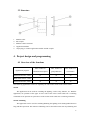
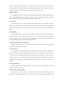
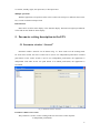
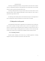
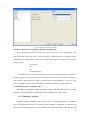
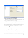
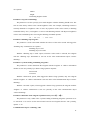
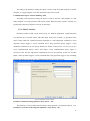
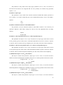
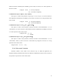
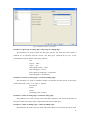
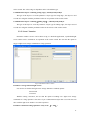
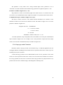
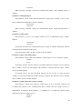
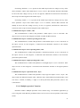
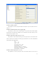
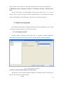
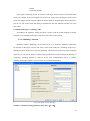
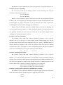
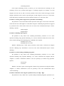
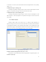
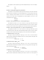
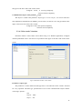
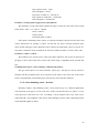
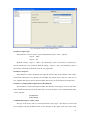
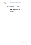
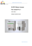
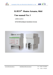
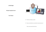
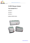
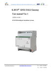
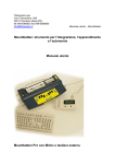
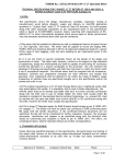
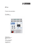
Guangzhou Video-Star Eletronnics Co.,Ltd. K-BUS Push Switch Sensor User manual-Ver. 1 CHKP-01/00.1 CHKP-02/00.1 CHKP-03/00.1 BTBC-01/00.1 BTBC-02/00.1 BTBC-03/00.1 Intelligent installation systems http://www.video-star.com.cn Contents 1. Summary ------------------------------------------------------------------------------------------------------------------ 3 2. Technical data ------------------------------------------------------------------------------------------------------------ 4 3. Structure and dimension diagram--------------------------------------------------------------------------------- 5 3.1 Dimension diagram ----------------------------------------------------------------------------------------------------- 5 3.2 Structure ------------------------------------------------------------------------------------------------------------------- 6 4. Project design and programming---------------------------------------------------------------------------------- 6 4.1 Overview of the functions -------------------------------------------------------------------------------------------- 6 5. Parameter setting description in the ETS ---------------------------------------------------------------------- 8 5.1 Parameter window ―General‖ ---------------------------------------------------------------------------------------- 8 5.2 Independent working mode ------------------------------------------------------------------------------------------ 9 5.2.1 ―Switching‖ function --------------------------------------------------------------------------------------------- 9 5.2.2 ―Dimming‖ function ------------------------------------------------------------------------------------------- 10 5.2.3 ―Blind‖ function ------------------------------------------------------------------------------------------------- 13 5.2.4 ―Value sender‖ function --------------------------------------------------------------------------------------- 15 5.2.5 ―Scene‖ function ------------------------------------------------------------------------------------------------ 17 5.2.6 ―Step-type switch‖ function ---------------------------------------------------------------------------------- 18 5.2.7 ―Short-long operation‖ function ---------------------------------------------------------------------------- 21 5.2.8 ―RTC operation mode‖ function ---------------------------------------------------------------------------- 23 5.2.9 ―Multiple operation‖ function --------------------------------------------------------------------------------27 5.3 Linked working mode ----------------------------------------------------------------------------------------------- 29 5.3.1 ―Switching‖ function ------------------------------------------------------------------------------------------- 29 5.3.2 ―Dimming‖ function ------------------------------------------------------------------------------------------- 30 5.3.3 ―Blind‖ function ------------------------------------------------------------------------------------------------- 33 5.3.4 ―Value sender‖ function --------------------------------------------------------------------------------------- 35 5.3.5 ―Value dimming sensor‖ function -------------------------------------------------------------------------- 36 5.3.6 ―Step-type switch‖ function ---------------------------------------------------------------------------------- 38 5.4 Parameter window ―LED function‖ ----------------------------------------------------------------------------- 41 2 1. Summary The switch sensor is used in building control systems, which can be mounted on a flush-mounted bus coupler. At the same time, the application module can be also connected with other devices for a system on the bus, and the functions are both simple to operation and intuitive. Users can program it according to the requirement to implement the function systematically. This manual provides detailed technical information about the switch sensor for users as well as assembly and programming details, and explains how to use the switch sensor by the application examples. The switch sensor can be used to control the switch, dimming, blinds, and RTC, etc. Each single rocker switch of the switch sensor correspond one LED with seven colors indication. The device can be installed in a conventional 86 mm wiring box. The bus coupler that connected the switch sensor connects to the bus though the EIB connection terminals and has no use for additional supply voltage. It is available to assign the physical address and set the parameters by Engineering design tools ETS with VD3/VD4 (higher than edition ETS3). The switch sensors have many functions that can be used in a wide variety of application areas. The following list provides an overview: switching and dimming control of blinds and shutters Sending of values, e.g. water line、brightness. recall and storage scene step-type switch setting the RTC operation mode Multiple operation LED indication Each rocker switch of a device can adopt any of the functions described above, and is independent of each other. Almost each function has two operating modes, one is that the function differentiates between whether the rocker switch is operated on the upper or lower push buttons, the other is that the function does not differentiate between whether the rocker switch is operated on the upper or lower push buttons. 3 2. Technical data Power supply Operating and display Bus voltage 21-30V DC,via the EIB bus Current consumption, bus <12mA Power consumption, bus <360mW Corresponding 1 LED indication for The LEDs have seven colors each rocker switch Programming LED and button For assignment of the physical address Number of button >20000 operation connections EIB/KNX Via bus connection terminal Temperature rang Operation – 5 °C ... 45 °C Storage – 25 °C ... 55 °C Transport – 25 °C ... 70 °C Design Embedded installation of equipment Dimensions 86×86mm (application module) 50.7×45.46×23.1mm (coupler) Installation in a conventional 86 mm wiring box Weight 0.1KG(application module) 0.1KG(coupler) Housing/color Plastic housing, white/gray/yellow/blue/pink/black Approvals EIB/KNX certificate CE mark In accordance with the EMC guideline and low voltage guideline 4 3. Structure and dimension diagram 3.1 Dimension diagram CHKP-03/00.1 BTBC-01/00.1 5 3.2 Structure 1. 2. 3. 4. 5. EIB bus cable Bus coupler EIB bus connect terminal Application module 10-pin plug, to connect application module and the coupler 4. Project design and programming 4.1 Overview of the functions Max. number of Max. number of Max. number of communication objects group addresses associations Push switch sensor, 1fold 12 24 24 Push switch sensor, 2 fold 24 48 48 Push switch sensor, 3fold 36 72 72 Application program The following applications can be set separately for each rocker switch of the switch sensor: Switch The application can be used for switching the lighting, such as relay, dimmer, etc. With the application, an operation of the upper or lower side of the rocker switch sends out a switching command. Or an operation or upon release of the rocker switch sends out a switching command. Switch / Dimming The application can be used for switching/dimming the lighting and is distinguished between long and short operation. The manner of dimming can be selected between start-stop dimming and 6 step-wise dimming. With the application, an operation of the upper or lower side of the rocker switch sends out a switching command or a dimming command. Or a short operation will execute switching and a long operation will execute dimming for the rocker switch. Blind and Shutter The application can make the Shutter or Roller blind movement or lamella adjustment, and there is distinguish between long and short operation, a short operation will execute movement and a long operation will execute adjustment/stop for the rocker switch. Value sender The application can be used for sending the different values or data types. With the application, an operation of the upper or lower side of the rocker switch sends out the different values. Or an operation and upon release of the rocker switch send out the different values or data types. Value dimming With the application, each operation of the upper or lower side of the rocker switch will increase or reduce a 1-byte value (percent or value from 0 to 127) via sending a 1-byte telegram. The 1-byte value can be connected with 1-byte brightness value objects from dimming actuators. Thus a dimming actuator can be dimmed brighter or darker. Light scene control with storage function With the application, a short operation will recall a scene and a long operation will storage the current scene for the rocker switch. Step-type switch The application is used to trigger different switching processed with each new operation of the rocker switch. Up to five switching levels can be activated. An operation of the upper or lower side of the rocker switch makes switching processed change to a stage higher or a stage lower. Or a short operation of the rocker switch will make switching processed change to a next level forward and a long operation will make switching processed back to the first level from every position. Short-long operation With the application, the different values can be sent out by a short operation or a long operation for the rocker switch. Setting the RTC operation mode The application can be used for adjusting the room thermostat. According to room temperature, humidity, refrigeration cycle, etc. you can switch to a different working mode, such 7 as comfort, standby, night, frost protection, or heat protection. Multiple operations With the application, an operation of the rocker switch can send up to 5 different values to the bus, to control 5 different output loads. LED function LED can be used for status display or the function display. The LED can light up in different colors and can also flash for alarm display. 5. Parameter setting description in the ETS 5.1 Parameter window “General” Parameter window ―General‖ can be shown in fig. 5.1. There used to set the working mode for each rocker switch, the rocker switch can be used as two independent push button or linked push button. If the rocker switch is used as two independent push button, the application is independent each other for the two push button. If as linked push button, the application is associated. Fig.5.1 Parameter window ―General‖ Parameter “Button 1-2/3-4 use” This parameter is used to set the working mode for each rocker switch. Options: 2 independent push buttons 8 Linked push button If selecting ―2 independent push buttons‖, the upper and lower sides of the rocker switch are used as two independent push buttons, and the application does not differentiate between whether the rocker switch is operated on the upper and lower sides. If selecting ―linked push button‖, the upper and lower sides of the rocker switch are used as linked push button, and the application differentiates between whether the rocker switch is operated on the upper and lower sides. The following sections details parameters and communication objects of each application in the two working modes, using one push button or one rocker switch as an example. 5.2 Independent working mode In the independent working mode, the applications do not differentiate between whether the rocker switch is operated on the upper and lower sides. In each case, the applications make a separate set of parameters and communication objects available for the upper and lower sides of the rocker switch. For example, a switching function can be realized via a rocker switch side while the other rocker switch side can be assigned with an additional ―button orientated‖ function. 5.2.1 “Switching” function Parameter window ―Switching‖ can be shown in fig. 5.2. With the application, a switching telegram is sent out for an operation or upon release of the rocker switch. 9 Fig.5.2 Parameter window ―Switching‖ Parameter “Reaction on rising edge”/“Reaction on falling edge” Via the parameters you can set which 1-bit value is sent out for every operation on rising edge and falling edge. This can be an ON telegram, an OFF telegram or a toggle telegram. Alternatively, no telegram can be sent out for a rocker switch operation using the ―No reaction‖ setting. Options: No reaction On Off Alternating on/off ―Alternating on/off‖ means that switching is always between ON and OFF. For example, if an ON telegram was last sent out, then a renewed operation of the rocker switch will trigger an OFF telegram. When the rocker switch is operated again, an ON telegram is sent out, etc. The rocker switch thus always remembers the last state and then switches over to the other value. Communication object “switching”, 1bit According to the parameter setting, the object is used to send out an ON telegram or an OFF telegram, or a toggle telegram via an operation or the releasing of the rocker switch. 5.2.2 “Dimming” function Parameter window ―Dimming‖ can be shown in fig. 5.3. With the application, a push button has two communication objects for switching and for dimming. A distinction is made between short operation and long operation. A short operation will execute switching; a long operation will 10 execute dimming. A ―switching‖ switching telegram is sent out on the 1-bit communication object. A ―relative dimming‖ dimming telegram is sent out on the 4-bit communication object. Fig.5.3 Parameter window ―Dimming‖ Parameter “duration of long operation=entry×0.1s”(3…30) The parameter is used to define the time which a long operation is recognized. Options: 3~30 Parameter “working mode of the push button for switching” This parameter is used to determine whether a short operation sends out an ON or an OFF telegram via a 1-bit communication object. Alternatively, for the selection ―alternating on/off‖, you can switch between switching on and switching off for every short operation, i.e. after a switch-on telegram has been sent out (or received), a switch-off telegram will be sent out for a renewed operation. After it is operated again, a switching-on telegram is sent out. Options: Deactivated Off On Alternating on/off Parameter “working mode of the push button for dimming” This parameter is used to determine whether a long operation sends out a dim brighter or a dim darker telegram via a 4-bit communication object. Alternatively, for the selection ―alternating brighter/darker‖, you can switch between dimming up and dimming darker for every long operation, i.e. after a dim brighter telegram has been sent out (or received), a dim darker telegram will be sent out for a renewed operation. After it is operated again, a dim brighter telegram is sent 11 out. Options: Darker Bright Alternating brighter/ darker Parameter “step size for dimming” The parameter is used to specify by how much brighter or darker dimming should occur. The sent out value always relates to the current brightness value. For example, a dimming actuator is currently dimmed to a brightness value of 70%. By operation of the rocker switch, a dimming command ―dim by 25% (1/4) brighter‖ is sent out. The dimming actuator will adjust its brightness value to 95% immediately after receiving the dimming command. Options: 1/1 ,1/2,1/4, …,1/32,1/64 Parameter “dimming stop telegram” The parameter is used to determine whether the release of the rocker switch will trigger the ―dimming stop‖ command or not. Options: Dimming stop is send Dimming stop is not send With the ―dimming stop is send‖ option, when the rocker switch is released, the telegram with the ―dimming stop‖ information is sent out on the 4-bit communication object ―relative dimming‖. Parameter “cyclical sending of dimming telegrams” The parameter is used to determine the telegram with the ―brighter‖ or ―darker‖ information whether is sent out cyclically by a durative long operation. Options: Deactivated Activated With the ―deactivated‖ option, when triggered a durative long operation, only one telegram with the ―brighter‖ or ―darker‖ information is sent out on the 4-bit communication object ―relative dimming‖. With the ―activated‖ option, when triggered a durative long operation, the telegram with the ―brighter‖ or ―darker‖ information is sent out cyclically on the 4-bit communication object ―relative dimming‖. Parameter “Duration of the telegram repetitions=entry×0.1 s(3…30)” The parameter is only visible if the ―cyclical sending of dimming telegrams‖ parameter is set to ―activated‖. It is used to set the interval time between two telegrams that are sent cyclically, options: 3~30 Communication object “switching”, 1bit 12 According to the parameter setting, the object is used to send out an ON telegram or an OFF telegram, or a toggle telegram via a short operation of the rocker switch. Communication object “relative dimming”, 4bit According to the parameter setting, the object is used to send out a dim brighter or a dim darker telegram via a long operation of the rocker switch. When the rocker switch is released, it is possible that a dim stop telegram is sent out via the object. 5.2.3 “Blind” function Parameter window ―blind‖ can be shown in fig. 5.4. With the application, a push button has two functions to be realized: shutter and roller blind. In the case of shutter, an operation of the rocker switch sends out a blind movement command or a slats adjustment command. A short operation always triggers a travel command and a long operation always triggers a slats adjustment command. You can specify whether the shutter control occurs via two 1-bit or two 1-byte communication objects ―travel‖ and ―adjust‖. If the communication object ―adjust‖ is selected to 1-bit, the slats adjustment command can be sent out cyclically. In the case of roller blind, a short operation triggers a travel command and a long operation trigger a stop command, the blind control occurs via two 1-bit communication objects ―travel‖ and ―stop‖. Fig.5.4 Parameter window ―Blind‖ Parameter “duration of long operation=entry×0.1s(3…30)” The parameter is used to define the time which a long operation is recognized. Options: 3~30 Parameter “cycle time of the telegram repetition= entry×0.1s(3…30)” 13 The parameter is only visible if the ―object type‖ parameter is set to ―1 bit‖. It is used to set the interval time between two telegrams that are sent cyclically for a durative long operation, options: 3~30 Parameter “object type” This parameter is only visible if the ―function switchover blinds/roller shutter‖ parameter is set to ―shutter‖. It is used to define the type of the communication objects ―travel‖ and ―adjust‖. Options: 1bit 1byte Parameter “Function switchover roller blind/ shutter” The parameter is used to determine whether a roller blind or shutter is to be driven by an operation. With the ―roller blind‖ setting, the value for the slats adjustment does not apply. Options: Shutter Roller blind Parameter “value for position down (%)”/“value for position up (%)” This parameter can only be set if ―1 byte‖ has been set as object type, which can be used to set the position (percent values) that a connected blind shall be lowered or raised to. Options: 0~100, the value 0% means travel up completely, the value 100% means travel down completely. Parameter “value for stats position down (%)”/“value for stats position up (%)” This parameter can only be set if ―1 byte‖ has been set as object type, which can be used to set the position (percent values) that a connected blind slat shall be opened or closed to. Options: 0~100, the value 0% means slat opened completely, the value 100% means closed completely. Communication object “travel”,1bit (shutter) This object is visible if the parameter ―object type‖ is set to ―1bit‖, it is used to send out a shutter movement command (UP or DOWN) on the bus via a short operation of the rocker switch. Telegram value ―0‖ UP ―1‖ DOWN Communication object “adjust”,1bit (shutter) This object is visible if the parameter ―object type‖ is set to ―1bit‖, it is used to send out a lamella adjustment command (UP or DOWN) on the bus via a long operation of the rocker switch. Telegram value ―0‖ lamella UP ―1‖ lamella DOWN Communication object “travel”,1byte (shutter) This object is visible if the parameter ―object type‖ is set to ―1byte‖, it is used to send out a 14 shutter movement command (UP or DOWN, percent values) on the bus via a short operation of the rocker switch. Telegram 0~100, 0 travel up completely 100 travel down completely. Communication object “adjust”,1byte (shutter) This object is visible if the parameter ―object type‖ is set to ―1byte‖, it is used to send out a slats adjustment command (UP or DOWN, percent values) on the bus via a long operation of the rocker switch. Telegram 0~100, 0 stat opened completely 100 stat closed completely. Communication object “travel”,1bit (roller blind) This object is visible if the parameter ―function switchover roller blind/shutter‖ is set to ―roller blind‖, it is used to send out a roller blind movement command (UP or DOWN) on the bus via a short operation of the rocker switch. Telegram value ―0‖ UP ―1‖ DOWN Communication object “stop”,1bit(roller blind) This object is visible if the parameter ―function switchover roller blind/shutter‖ is set to ―roller blind‖, which is used to send out a roller blind stop telegram on the bus via a long operation of the rocker switch. Telegram value ―0‖ or ―1‖ stop 5.2.4 “Value sender” function Parameter window ―value sender‖ can be shown in fig. 5.5. With the application, two telegrams with the predefined values from two different communication objects can be sent out for an operation or upon release of the rocker switch. 15 Fig.5.5 Parameter window ―value sender‖ Parameter “object type for rising edge”/“object type for falling edge” The parameters are used to define the data types that are sent when the rocker switch is actuated for an operation and the release. The data types specified the bit size of the communication objects and the value range. Options: 1bit 1byte 0…100% 1byte 1…255 2byte signed -32768…32767 2byte unsigned 0…65535 4byte signed -2147483648…2147483647 4byte unsigned 0…4294967295 Parameter “reaction on rising edge”/“reaction on falling edge” The parameters are used to determine whether an operation and the release of the rocker switch send out the ―value 1‖ or ―value 2‖. Options: No reaction Value 1 Value 2 Alternating value 1/value 2 Parameter “value1 for rising edge”/“value2 for rising edge” The parameters are used to specify value1 and value2 which are sent out for an operation of the rocker switch. The values range is dependent on the selected data types. Parameter “value1 for falling edge”/“value2 for falling edge” The parameters are used to specify value1 and value2 which are sent out for the release of the 16 rocker switch. The values range is dependent on the selected data type. Communication object “switching (rising edge)”, 1bit/1byte/2byte/4byte The type of the object is set in the parameter ―object type for rising edge‖, the object is used to send out a telegram with the predefined value for an operation of the rocker switch. Communication object “switching(falling edge)”, 1bit/1byte/2byte/4byte The type of the object is set in the parameter ―object type for falling edge‖, the object is used to send out a telegram with the predefined value for the release of the rocker switch. 5.2.5 “Scene” function Parameter window ―Scene‖ can be shown in fig. 5.6. With the application, a predefined light scene number can be recalled for an operation of the rocker switch. The user has the option to trigger a light scene storage command via a long operation. Fig.5.6 Parameter window ―Scene‖ Parameter “storage function light scenes” It is used to set whether the light scene storage function is enabled, options: Deactivated Activated With the setting ―activated‖, the user has the option of sending out a light scene storage command via a long operation. The same 1-byte communication object that is used for this can also recall the light scene number via a short operation. Parameter “duration of long operation= entry×0.1s”(3…100)” 17 The parameter is only visible if the ―storage function light scenes‖ parameter is set to ―activated‖. It is used to define the time which a long operation is recognized. Options: 3~100 Parameter “number of light scene (1…64)” The parameter is used to set an arbitrary light scene number from 1 to 64 which can be sent out via the 1-byte communication object ―light scene number‖ for operation of the rocker switch. Communication object “Number of light scene”, 1byte The object is used to send out a scene number and the information as to whether a scene should be recalled or the current scene should be stored. The number of light scene is set in the parameter ―Number of light scene‖. Telegram code 8 bit: FXNNNNNN F: 0—Scene is recalled 1—Scene is stored X:Not used NNNNNN:Number of the scene(0…63) 1-64 in the parameter setup corresponds to the scene number 0-63 sent by the communication object ―Number of light scene‖. For example, scene 1 in the parameter setup has the same output result as scene 0 in the communication object ―Number of light scene‖. 5.2.6 “Step-type switch” function Parameter window ―step-type switch‖ can be shown in fig. 5.7. With the application, the user can trigger different switching processed with each new operation of the rocker switch. Up to five switching levels can be activated. A short and long operation can be differentiated between for the operation of the rocker switch. For a short operation of the rocker switch, a next level forward is switched to in each case. For a long operation, the first level is activated. Thus a long operation can jump back from every position to the first level without having to run through the remaining levels. 18 Fig.5.7 Parameter window ―step-type switch‖ Parameter “Number of objects” The parameter is used to specify the number of the levels. Up to five levels can be switched. For every level, its own 1-bit communication object is available. Options: 1…5 Parameter “Evaluation period= entry×0.1s”(10…50)” The parameter is used to set the evaluation period, i.e. the period of time in which complete the first object to the final object sending out via an operation, up to five objects can be sent. Options: 10~50 Parameter “duration of long operation=entry×0.1s (3…50)” The parameter is used to define the time which a long operation is recognized, and switched back to the first level. Options: 3~50 Parameter “sending of objects” The parameter is used to specify whether the object values for every rocker switch operation are sent out or only if the object values have changed since the last sending out. Options: For operation For change of value The three objects as an example to illustrate the difference between two options(normal, x of n): Operations Binary code 0 objects Stage3 Stage2 Stage1 000 Off Off Off 1 001 Off Off On 2 011 Off On On 19 3 111 On On On 4 111 On On On …… …… …… …… …… With the setting ―for operation‖, the three object values are sent out for every operation. Such as the above table from the 1st to the 2nd operation, stage 1 object sends the value of 1, for a while stage 2 object will send the value of 1, finally, stage 3 object will send the value of 0. The total time that the three objects are sent out can be set in the parameter ―Evaluation period= entry×0.1s‖ With the setting ―for change of value‖, only the object that values have changed compared with the last values is sent out for every operation. Such as the above table from the 1st to the 2nd operation, only stage 2 object value has changed, so only stage 2 object sends the value of 1. If the rocker switch is a long operation, the operation is switched back to the 0th operation,i.e. 000. Parameter “object values” The parameter is used to define whether the object values are sent out ―invert‖ or ―normal‖ via their associated 1-bit communication objects, options: Normal Inverse With the setting ―normal‖, all 1-bit communication objects of the individual levels sent out their values normal. With the setting ―inverse‖, all 1-bit communication objects of the individual levels sent out their values inverted. The three objects as an example to illustrate the difference between two options, their object values are just opposite. As follows: Normal Operations Inverse objects objects Binary code Binary code Stage3 Stage2 Stage1 Stage3 Stage2 Stage1 0 000 Off Off Off 111 On On On 1 001 Off Off On 110 On On Off 2 011 Off On On 100 On Off Off 3 111 On On On 000 Off Off Off 4 111 On On On 000 Off Off Off …… …… …… …… …… …… …… …… …… 20 Parameter “bit pattern of object values” The parameter is used to determine the way of bit pattern of object values. Options: x of n 1 of n The three objects as an example to illustrate their difference, as follows (normal, n=3): X of n Operations 1 of n objects objects Binary code Binary code Stage3 Stage2 Stage1 Stage3 Stage2 Stage1 0 000 Off Off Off 000 Off Off Off 1 001 Off Off On 001 Off Off On 2 011 Off On On 010 Off On Off 3 111 On On On 100 On Off Off 4 111 On On On 100 On Off Off …… …… …… …… …… …… …… …… …… With the setting ―x of n‖, the binary coding sequence of bit pattern of object values is 000-001-011-111. So the object values have changed step by step. With the setting ―1 of n‖, the binary coding sequence of bit pattern of object values is 000-001-010-100. Only one of the object values is 1 for every operation, and the object values have changed with certain regularity. Communication object “Switching stage1”to “switching stage 5”, 1bit The number of these objects (max.5) is set in the parameter ―Number of objects‖. The objects send out the values or some of the values for every new operation of the rocker switch. 5.2.7 “Short-long operation” function Parameter window ―short-long operation‖ can be shown in fig. 5.8. With the application, a telegram with different predefined values can be sent out for a short or long operation of the rocker switch. 21 Fig.5.8 Parameter window ―short-long operation‖ Parameter “object type” The parameter is used to define the data types that are sent when the rocker switch is actuated via a short or long operation. The data types specified the bit size of the communication objects and the value range. Options: 1bit 1byte 0…100% 1byte 1…255 2byte signed -32768…32767 2byte unsigned 0…65535 4byte signed -2147483648…2147483647 4byte unsigned 0…4294967295 Parameter “reaction on short operation” The parameters are used to determine whether the rocker switch sends out the ―value1‖ or ―value2‖via a short operation. Options: No reaction Value 1 Value 2 Alternating value 1/value 2 Parameter “value 1/2 for short operation” The parameters are used to specify value1 and value2 which are sent out for a short operation of the rocker switch. The values range is dependent on the selected data type. Parameter “reaction on long operation” The parameters are used to determine whether the rocker switch sends out the ―value1‖ or 22 ―value2‖via a long operation. Options: No reaction Value 1 Value 2 Alternating value 1/value 2 Parameter “value 1/2 for long operation” The parameters are used to specify value1 and value2 which are sent out for a long operation of the rocker switch. The values range is dependent on the selected data type. Parameter “duration of long operation= entry×0.1s (3…30)” The parameter is used to define the time which a long operation is recognized. Options: 3~30 Communication object “Value for short operation”, 1bit/1byte/2byte/4byte The type of the object is set in the parameter ―object type‖, the object is used to send out a telegram with the predefined value for a short operation of the rocker switch. The predefined value and data types can be freely selected in the parameters. Communication object “Value for long operation”, 1bit/1byte/2byte/4byte The type of the object is set in the parameter ―object type‖. The object is used to send out a telegram with the predefined value for a long operation of the rocker switch. The predefined value and data types can be freely selected in the parameters. 5.2.8 “RTC operation mode” function Parameter window ―RTC operation mode‖ can be shown in fig. 5.9. With the application, an operation mode switchover for connected room thermostats can be carried out for an operation of a rocker switch side. The application offers two object types for output, one is three 1-bit communication objects ―operating mode comfort‖, ―operating mode night‖, ―operating mode frost‖, and the other is a 1-byte communication object ―operating mode‖. In the case of 1-byte, different values mean different operation modes, such as 0=auto, 1=comfort, 2=standby, etc. The function can be temporarily blocked via this 1-bit ―enable‖ communication object. 23 Fig.5.9 Parameter window ―RTC operation mode‖ Parameter “object type for output” The parameter is used to determine the size of the output communication object for the RTC operation. Options: 1bit 1byte The selection ―1-bit‖ is used for control of room thermostats that have 1-bit communication objects for operating mode switchover. The selection ―1-byte‖ is used for control of room thermostats that have 1-byte communication object for operation mode switchover. In this case, the values mean 0=auto, 1=comfort, 2=standby, 3=night, 4=frost/heat protection, 5~255= not allowed. Parameter “operating mode” The parameter is used to specify the operating mode, options: Auto Comfort Standby Night Frost protection, Heat protection The ―auto‖ mode can only be set if the ―object type for output‖ parameter is set to ―1-byte‖, with the selection of ―auto‖, the value ―0‖ is sent out on the 1byte object. For a connected room thermostat, this means that for every new operation, the individual operating modes ―comfort‖, ―standby‖, and ―night‖ will be switched between. 24 If the ―object type for output‖ parameter is set to ―1-bit‖ and with the selection of ―comfort‖, the follow ―send comfort object‖ and ―sending frost protection‖ parameters will visible. If the ―object type for output‖ parameter is set to ―1-bit‖ and with the selection of ―standby‖, the follow ―send comfort object‖ 、 ―sending frost protection‖ and ―sending night object‖ parameters will visible. If the ―object type for output‖ parameter is set to ―1-bit‖ and with the selection of ―night‖, the follow ―send comfort object‖ 、 ―sending frost protection‖ and ―sending night object‖ parameters will visible. If the ―object type for output‖ parameter is set to ―1byte‖, the value ―1‖ is sent out on the 1-byte object and a connected room thermostat switches to the comfort operation mode, the value ―2‖ is sent out on the 1-byte object and a connected room thermostat switches to the standby operation mode, the value ―3‖ is sent out on the 1-byte object and a connected room thermostat switches to the night operation mode, the value ―4‖ is sent out on the 1-byte object and a connected room thermostat switches to the Frost/Heat protection operation mode. If the ―object type for output‖ parameter is set to ―1bit‖, when the object ―comfort operating mode‖ sends a telegram ―1‖ on operating switch, and other objects send telegrams ―0‖, right now a connected room thermostat switches to the comfort operation mode; when the object ―night operating mode‖ sends a telegram ―1‖ on operating switch, and other objects send telegrams ―0‖, right now a connected room thermostat switches to the night operation mode; when all objects send telegrams ―0‖ on operating switch, right now a connected room thermostat switches to the standby operation mode. When the operation mode is set to the Frost/Heat protection operation mode, other operation modes of communication objects and parameters will be not visible. Parameter “send comfort object” This parameter will be visible when the parameter ―object type for output‖ is set to ―1bit‖, here set whether the comfort mode is activated. Options: Deactivated Activated When selecting ―activated‖ option, the communication object ―comfort operating mode‖ is enabled. Parameter “sending frost protection” This parameter will be visible when the parameter ―object type for output‖ is set to ―1bit‖, here set whether the frost/heat protection mode is activated. Options: Deactivated 25 Activated When selecting ―activated‖ option, the communication object ―frost operating mode‖ is enabled. Parameter “send night object” This parameter will be visible when the parameter ―object type for output‖ is set to ―1bit‖, here set whether the night mode is activated. Options: Deactivated Activated When selecting ―activated‖ option, the communication object ―night operating mode‖ is enabled. Parameter “enable object” This parameter is used to set whether enable the 1bit communication object ―enable‖. Options: Deactivated Activated If selecting ―activated‖, the communication object ―enable‖ is enabled, and the RTC function can temporarily be blocked via the object. If selecting ―deactivated‖, the RTC function is always enabled. Parameter “object value enable object” This parameter is only visible if the parameter ―enable object‖ is set to ―activated‖. Options: Normal Invert If selecting ―normal‖, the RTC function is normally enabled, the function is active when the object ―enable‖ receives an ON telegram. The function is blocked when the object ―enable‖ receives an OFF telegram. If selecting ―invert‖, the above-described behavior can be reversed, i.e. when the object ―enable‖ receives an ON telegram, the RTC function is blocked. The function is active when the object ―enable‖ receives an OFF telegram. Parameter “enable object after return of voltage” The parameter is visible if the parameter ―enable object‖ is set to ―activated‖, which is used to defined the behavior of the communication object ―enable‖ after bus voltage recovery. A determination is made here about whether a ―1‖ (enabled) or a ―0‖ (blocked) is present on the enable object after bus voltage recovery. Blocked Enable 26 If selecting ―blocked‖, a ―0‖ is present on the enable object after bus voltage recovery. If the above parameter ―object value enable object‖ is set to ―invert‖, then the RTC function will initially be active after bus voltage recovery, or else it is opposite, and then here must first be activated via the receipt of an ON telegram on the enable object. If selecting ―enable‖, a ―1‖ is present on the enable object after bus voltage recovery. If the above parameter ―object value enable object‖ is set to ―normal‖, then the RTC function will initially be active after bus voltage recovery, or else it is opposite, and then here must first be activated via the receipt of an OFF telegram on the enable object. Communication object “enable”, 1bit This communication is visible if the parameter ―enable object‖ is set to ―activated‖. The object receives an ON or OFF telegram to disable or enable the RTC function. Communication object “Comfort operating mode”, 1bit This communication is visible if the parameter ―send comfort object‖ is set to ―activated‖. If the object receives an ON telegram, a connected room thermostat switches to the comfort operation mode. Communication object “Frost operating mode”, 1bit This communication is visible if the parameter ―send frost protection‖ is set to ―activated‖. If the object receives an ON telegram, a connected room thermostat switches to the frost/heat protection operation mode. Communication object “Night operating mode”, 1bit This communication is visible if the parameter ―send night object‖ is set to ―activated‖. If the object receives an ON telegram, a connected room thermostat switches to the night operation mode. Communication object “Operation mode”, 1byte This communication is visible if the parameter ―object type for output‖ is set to ―1byte‖. The object sends out different telegram values, different values mean different operation modes, such as 0=auto, 1=comfort, 2=standby, 3= night, 4=or Frost protection, Heat protection, values 5~255 is not allowed. 5.2.9 “Multiple operation” function Parameter window ―Multiple operation‖ can be shown in fig. 5.10. With the application, up to five telegrams with different predefined values can be sent out for an operation of the rocker switch. 27 Fig.5.10 Parameter window ―Multiple operation‖ Parameter “Number of objects” The parameter is used to specify the number of the objects. Up to five objects can be set. Options: 1…5 Parameter “Evaluation period= entry×0.1s”(10…50)” The parameter is used to set the evaluation period, i.e. the period of time in which complete the first object to the final object sending out via an operation of the rocker switch, up to five objects can be sent. Options: 10~50 Parameter “object type for object X (X=1, 2, 3, 4, 5)” The parameter is used to define the data types for the objects that are sent when the rocker switch is actuated via an operation. The data types specified the bit size of the communication objects and the value range. Options: 1bit 1byte 0…100% 1byte 1…255 2byte signed -32768…32767 2byte unsigned 0…65535 2byte float -671088, 64 …670760, 96 4byte signed -2147483648…2147483647 4byte unsigned 0…4294967295 Parameter “Value for object X (X=1, 2, 3, 4, 5)” The parameters are used to specify the value of the objects which are sent out for an 28 operation of the rocker switch. The value range is dependent on its data type in the parameter. Communication object “Switching 1 actuation” to “Switching 5 actuation”, 1bit/1byte/2byte/ 4byte The type of the object is set in the parameter ―object type for object X (X=1, 2, 3, 4, 5)‖, the object is used to send out a telegram with the predefined value for an operation of the rocker switch. The predefined value and data types can be freely selected in the parameters. 5.3 Linked working mode In the linked working mode, the applications differentiate between whether the rocker switch is operated on the upper and lower side of the rocker switch. 5.3.1 “Switching” function Parameter window ―switching‖ can be shown in fig. 5.11. With the ―switching‖ application, an operation of the upper or lower side of the rocker switch sends out a switching telegram. Fig.5.11 Parameter window ―Switching‖ Parameter “working model of upper/lower push buttons” The parameter is used to define whether switching on or switching off occurs via the upper or the lower side of the rocker switch. Options: On/Off 29 Off/On Alternating On/Off If the option ―alternating on/off‖ is selected, switching is always between ON and OFF. That means, for example, if an ON telegram was last sent out, then a renewed operation of the rocker switch will trigger an OFF telegram. When the rocker switch is operated again, an ON telegram is sent out, etc. The rocker switch thus always remembers the last state and then switches over to the other value. Communication object “switching”, 1bit According to the parameter setting, the object is used to send out an ON telegram or an OFF telegram via an operation of the upper or the lower side of the rocker switch. 5.3.2 “Dimming” function Parameter window ―Dimming‖ can be shown in fig. 5.12. With the ―dimming‖ application, an operation of the upper or lower side of the rocker switch sends out a switching telegram or a dimming telegram. In the case of step-wise dimming, a distinction is made between short and long operation, you can specify whether a short or long operation will execute switching or dimming. A ―switching‖ switching telegram is sent out on the 1-bit communication object. A ―relative dimming‖ dimming telegram is sent out on the 4-bit communication object. Fig.5.12 Parameter window ―Dimming‖ Parameter “duration of long operation=entry×0.1s”(3…30) 30 The parameter is used to define the time which a long operation is recognized. Options:3~30 Parameter “manner of dimming” You can select between the two dimming manner ―start-stop dimming‖ and ―step-wise dimming‖ via this parameter. Options: Start-stop dimming Step-wise dimming With the ―start-stop dimming‖ option, it means that exactly two 4-bit telegrams for dimming are always sent out. For triggering of a dimming command, a telegram with the information ―dim by 100% brighter‖ or ―dim by 100% darker‖ is sent out. When the rocker switch is released, the second telegram is sent out with the ―dimming stop‖ information. With the ―step-wise dimming‖ option, the dimming manner is the step-wise dimming. You can set a telegram with the ―brighter‖ or ―darker‖ information whether is sent out cyclically by a long operation. And when the rocker switch is released, you can also set the telegram with the ―dimming stop‖ information whether is sent out. Parameter “step size for dimming” The parameter is only visible if the ―manner of dimming‖ parameter is set to ―step-wise dimming‖. Here you can specify by how much brighter or darker dimming should occur. The sent out value always relates to the current brightness value. For example, a dimming actuator is currently dimmed to a brightness value of 70%. By operation of the rocker switch, a dimming command ―dim by 25% (1/4) brighter‖ is sent out. The dimming actuator will adjust its brightness value to 95% immediately after receiving the dimming command. Options: 1/1 ,1/2,1/4, …,1/32,1/64 Parameter “dimming functionality” The parameter is only visible if the ―manner of dimming‖ parameter is set to ―step-wise dimming‖. It is used to define the functionality of the dimming. You can set whether a switching telegram will be sent out for a short operation of the rocker switch and a dimming telegram will be sent out for a long operation or whether a long operation will cause a switching telegram to be sent out and a short operation will cause a dimming telegram to be sent out. Options: Short operation dimming, long operation switching Short operation switching, long operation dimming Parameter “working mode of upper/lower push buttons for switching” The parameter is used to determine whether operation of the upper or lower side of the rocker switch will send out an ON or an OFF telegram or a toggle telegram. Options: On/Off Off/On 31 Alternating On/Off If the option alternating on/off is selected, you can switch between switching on and switching off for every operation that triggers a switching telegram. For example, if an ON telegram was last sent out, then a renewed operation of the rocker switch will trigger an OFF telegram. When the rocker switch is operated again, an ON telegram is sent out, etc. The rocker switch thus always remembers the last state and then switches over to the other value. Parameter “working mode of upper/lower push button for dimming” The parameter is used to determine whether operation of the upper or lower side of the rocker switch will sent out a dim brighter or a dim darker telegram. A dimming telegram that is triggered by operation of the rocker switch will be sent out on the 4-bit communication object ―relative dimming‖. Options: Darker/ Bright Bright/ Darker Parameter “dimming stop telegram” The parameter is only visible if the ―dimming functionality‖ parameter is set to ―short operation switching, long operation dimming‖. It is used to determine whether the release of the rocker switch will trigger the ―dimming stop‖ command or not. Options: Dimming stop is send Dimming stop is not send With the ―dimming stop is send‖ option, when the rocker switch is released, the telegram with the ―dimming stop‖ information is sent out on the 4-bit communication object ―relative dimming‖. Parameter “cyclical sending of dimming telegrams” The parameter is only visible if the ―dimming functionality‖ parameter is set to ―short operation switching, long operation dimming‖. It is used to determine the telegram with the ―brighter‖ or ―darker‖ information whether is sent out cyclically by a durative long operation. Options: Deactivated Activated With the ―activated‖ option, when triggered a durative long operation, the telegram with the ―brighter‖ or ―darker‖ information is sent out cyclically on the 4-bit communication object ―relative dimming‖. Parameter “Duration of the telegram repetitions=entry×0.1 s(3…30)” The parameter is only visible if the ―cyclical sending of dimming telegrams‖ parameter is set 32 to ―activated‖. It is used to set the interval time between two telegrams that are sent cyclically, options: 3~30 Communication object “switching”, 1bit According to the parameter setting, the object is used to send out an ON telegram or an OFF telegram via an operation of the upper or the lower side of the rocker switch. Communication object “relative dimming”, 4bit According to the parameter setting, the object is used to send out a dim brighter or a dim darker telegram, or a dim stop telegram via an operation of the upper or the lower side of the rocker switch. 5.3.3 “Blind” function Parameter window ―blind‖ can be shown in fig. 5.13. With the ―blind‖ application, an operation of the upper or lower side of the rocker switch sends out a blind movement command or a slats adjustment command. A short operation always triggers a travel command and a long operation always triggers a slats adjustment command. You can specify whether the blind control occurs via two 1-bit or two 1-byte communication objects ―travel‖ and ―adjust‖. Fig.5.13 Parameter window ―Blind‖ Parameter “duration of long operation=entry×0.1s (3…30)” The parameter is used to define the time which a long operation is recognized. Options: 3~30 Parameter “object type” 33 This parameter is used to define the type of the communication objects ―travel‖ and ―adjust‖. Options: 1bit 1byte Parameter “working mode of upper/lower push buttons” The parameter is used to determine whether operation of the upper or lower side of the rocker switch will send out commands for movement and adjustment. For a short operation of the rocker switch, a moving up or down telegram is sent out on a 1-bit communication object. For a long operation of the rocker switch, a slat adjustment up or down telegram is sent out on a 1-bit communication object. Options: Down/ Up Up/ Down Parameter “value for position down (%)”/“value for position up (%)” This parameter can only be set if ―1 byte‖ has been set as object type, which can be used to set the position (percent values) that a connected blind shall be lowered or raised to. Options: 0~100, the value 0% means travel up completely, the value 100% means travel down completely. Parameter “value for stats position down (%)”/“value for stats position up (%)” This parameter can only be set if ―1 byte‖ has been set as object type, which can be used to set the position (percent values) that a connected blind slat shall be opened or closed to. Options: 0~100, the value 0% means slat opened completely, the value 100% means closed completely. Communication object “travel”,1bit This object is visible if the parameter ―object type‖ is set to ―1bit‖, it is used to send out a shutter movement command (UP or DOWN) on the bus via a short operation of the upper or the lower side of the rocker switch. Telegram value ―0‖ UP ―1‖ DOWN Communication object “adjust”,1bit This object is visible if the parameter ―object type‖ is set to ―1bit‖, it is used to send out a lamella adjustment command (UP or DOWN) on the bus via a long operation of the upper or the lower side of the rocker switch. Telegram value ―0‖ lamella UP ―1‖ lamella DOWN Communication object “position”,1byte This object is visible if the parameter ―object type‖ is set to ―1byte‖, it is used to send out a shutter movement command (UP or DOWN, percent values) on the bus via a short operation of 34 the upper or the lower side of the rocker switch. Telegram 0~100, 0 travel up completely 100 travel down completely. Communication object “Slats position”,1byte This object is visible if the parameter ―object type‖ is set to ―1byte‖, it is used to send out a slats adjustment command (UP or DOWN, percent values) on the bus via a long operation of the upper or the lower side of the rocker switch. Telegram 0~100, 0 slats opened completely 100 slats closed completely. 5.3.4 “Value sender” function Parameter window ―value sender‖ can be shown in fig. 5.14. With the application, a telegram with the predefined value is sent out for an operation of the upper or the lower side of the rocker switch. Fig.5.14 Parameter window ―value sender‖ Parameter “object type” The parameter is used to define the data type that is sent when the rocker switch is actuated for every operation. The data type specified the bit size of the communication objects and the value range. Options: 1bit 1byte 0…100% 1byte 1…255 35 2byte signed -32768…32767 2byte unsigned 0…65535 2byte float -671088, 64 …670760, 96 4byte signed -2147483648…2147483647 4byte unsigned 0…4294967295 Parameter “working mode of upper/lower push buttons” This parameter is used to determine whether the upper or the lower side of the rocker switch sends out the ―value 1‖ or ―value 2‖. Options: Value 1//Value 2 Value 2/Value 1 Alternating Value 1/Value 2 If the option ―alternating value1/value2‖ is selected, switching is always between value1 and value2. That means, for example, if value1 was last sent out, then a renewed operation of the rocker switch will trigger value2. When the rocker switch is operated again, value1 is sent out, etc. The rocker switch thus always remembers the last state and then switches over to the other value. Parameter “value1”/“value2” The parameters are used to specify value1 and value2 which are sent out for an operation of the upper or lower side of the rocker switch. The values range is dependent on the selected data type. Communication object “value switching”, 1bit/1byte/2byte/4byte The type of the object is set in the parameter ―object type‖, the object is used to send out a telegram with the predefined value for an operation of the upper or the lower side of the rocker switch. The predefined value and data types can be freely selected in the parameters. 5.3.5 “Value dimming sensor” function Parameter window ―value dimming sensor‖ can be shown in fig. 5.15. With the application, each operation of the upper or lower side of the rocker switch will increase or reduce a 1-byte value (percent or value from 0 to 127) via sending a 1-byte telegram. The 1-byte value can be connected with 1-byte brightness value objects from dimming actuators. Thus a dimming actuator can be dimmed brighter or darker. 36 Fig.5.15 Parameter window ―value dimming sensor‖ Parameter “object type” The parameter is used to set the 1-byte communication object ―value‖. Options: 1byte 0…100% 1byte 0…255 With the setting ―1-byte 0…100%‖, the momentary value is increased or reduced by a percent amount for every operation. With the setting ―1-byte 0…255‖, the momentary value is increased or reduced by an absolute value for every operation. Parameter “Step size” The parameter is used to determine how large the percent value or the absolute value will be increased or reduced for every operation. For example, the current value is 40%, for a step size of 10%, and then the current value is increased from 40% to 50% for an operation (for an increase). Parameter “working mode of upper/lower push buttons” The parameter is used to determine whether the operation of the upper or lower side of the rocker switch increased or lowers the value that is sent out from the 1-byte communication object ―value‖. Options: Bright/Darker Darker/Bright Communication object “value”, 1byte The type of the object value is set in the parameter ―object type‖. The object is used to send out a telegram with the predefined value for an operation of the upper or the lower side of the 37 rocker switch. The predefined value is set in the parameter ―step size‖. Telegram value 0~50% Or 0~127 5.3.6 “Step-type switch” function Parameter window ―step-type switch‖ can be shown in fig. 5.16. With the application, the user can trigger different switching processed with each new operation of the upper or lower side of the rocker switch. Up to five switching levels can be activated. Depending on the setting, a stage higher or a stage lower can thus be switched to. Fig.5.16 Parameter window ―step-type switch‖ Parameter “Number of objects” The parameter is used to specify the number of the levels. Up to five levels can be switched. For every level, its own 1-bit communication object is available. Options: 1…5 Parameter “Evaluation period= entry×0.1s”(10…50)” The parameter is used to set the evaluation period, i.e. the period of time in which complete the first object to the final object sending out via a multiple operation, up to four objects can be sent. Options: 10~50 Parameter “working mode of upper/lower push buttons” The parameter is used to specify whether an operation of the upper or lower side of the rocker switch switches one stage up or lower. Options: Up/Down 38 Down/Up The three objects as an example to illustrate the working mode, as follows: (normal, x of n) operations Binary code 0 objects Stage 3 Stage2 Stage 1 000 Off Off Off 1 001 Off Off On 2(current) 011 Off On On 3 111 On On On 4 111 On On On …… …… …… …… …… With the setting ―up/down‖, the current operation is 2. If an operation of the upper rocker switch side switches one stage up, the next operation will be 3. If an operation of the lower rocker switch side switches one stage lower, the next operation will be 1. With the setting ―down/up‖, the current operation is 2. If an operation of the upper rocker switch side switches one stage lower, the next operation will be 1. If an operation of the lower rocker switch side switches one stage up, the next operation will be 3. Parameter “sending of objects” The parameter is used to specify whether the object values for every rocker switch operation are sent out or only if the object values have changed since the last sending out. Options: For operation For change of value Above form as an example to illustrate the difference between two options: With the setting ―for operation‖, the three object values are sent out for every operation. Such as the above table from the 1st to the 2nd operation, stage 1 object sends the value of 1, for a while stage 2 object will send the value of 1, finally, stage 3 object will send the value of 0. The total time that the three objects are sent out can be set in the parameter ―Evaluation period= entry×0.1s‖ With the setting ―for change of value‖, only the object that values have changed compared with the last values is sent out for every operation. Such as the above table from the 1st to the 2nd operation, only stage 2 object value has changed, so only stage 2 object sends the value of 1. Parameter “object values” The parameter is used to define whether the object values are sent out ―invert‖ or ―normal‖ via their associated 1-bit communication objects, options: Normal Inverse With the setting ―normal‖, all 1-bit communication objects of the individual levels sent out their values normal. 39 With the setting ―inverse‖, all 1-bit communication objects of the individual levels sent out their values inverted. The three objects as an example to illustrate the difference between two options, their object values are just opposite. As follows: Normal Operations Inverse objects objects Binary code Binary code Stage3 Stage2 Stage1 Stage3 Stage2 Stage1 0 000 Off Off Off 111 On On On 1 001 Off Off On 110 On On Off 2 011 Off On On 100 On Off Off 3 111 On On On 000 Off Off Off 4 111 On On On 000 Off Off Off …… …… …… …… …… …… …… …… …… Parameter “bit pattern of object values” The parameter is used to determine the way of the bit pattern of object values. Options: x of n 1 of n The three objects as an example to illustrate their difference, as follows (normal, n=3): X of n Operations 1 of n objects objects Binary code Binary code Stage3 Stage2 Stage1 Stage3 Stage2 Stage1 0 000 Off Off Off 000 Off Off Off 1 001 Off Off On 001 Off Off On 2 011 Off On On 010 Off On Off 3 111 On On On 100 On Off Off 4 111 On On On 100 On Off Off …… …… …… …… …… …… …… …… …… With the setting ―x of n‖, the binary coding sequence of bit pattern of object values is 000-001-011-111. So the object values have changed step by step. With the setting ―1 of n‖, the binary coding sequence of bit pattern of object values is 000-001-010-100. Only one of the object values is 1 for every operation, and the object values have changed with certain regularity. Communication objects “Switching stage1”to “switching stage 5”, 1bit 40 The number of these objects (max.5) is set in the parameter ―Number of objects‖. The objects send out the values or some of the values for every new operation of the upper or the lower side of the rocker switch. 5.4 Parameter window “LED function” Parameter window ―LED function‖ can be shown in fig. 5.16. Each rocker switch has a LED, which can be used for status display or for the function display. The LED can light up in different colours. The LED can also flash for alarm display. LED indication and the button operation are independent of each other. Their parameters and communication objects available can be set separately. Fig.5.16 Parameter window ―LED function‖(1bit) 41 Fig.5.16 Parameter window ―LED function‖(1byte) Parameter “LED function enable” It is used to set whether LED function is enabled, options: Deactivated Activated If the option ―activated‖ is selected, the object ―Status‖ will be enabled. Parameter “Object type for status object” It is used to set type for the object ―Status‖. The object status can either be set to the size ―1 bit‖ or ―1 byte‖. Options: 1bit 1byte With the setting ―1bit‖, the ―colour for off‖ and ―colour for on‖ parameters will be visible. If the communication object ―Status‖ received an ON telegram, the LED takes on the colour that is stored in the ―colour for on‖ parameter. If the communication object ―Status‖ received an OFF telegram, the LED takes on the colour that is stored in the ―colour for off‖ parameter. With the setting ―1 byte‖, the ―colour for Zone 1(corresponds to 0%)‖、―colour for Zone 2(1% to Zone 3)‖、……、 and ―colour for Zone 5 (100%)‖ parameters will be visible. When a value telegram is received on the object ―Status‖, the LED takes on the colour that depends on the parameter settings ―colour for Zone …‖ Note: the LED function is not action after voltage recovery, unless the object received a telegram, and the LED will take on the colour according to the parameter settings. 42 Parameter “colour for off/on” or “colour for Zone…” These parameters are used to set the colour that the LED takes on when the object ―Status‖ received a telegram. Options: Off Red Green …… Orange Parameter “Threshold between Zone2 and Zone 3 (Zone3 and Zone 4)” This parameter is visible in the parameter ―object type for status object‖ with ―1 byte 0…100%‖. In this type of case, LED indication can be divided into five Zone, the colour that the LEDs take on for each Zone can be set in the parameter ―colour for Zone …‖. Here the parameter is used to set the threshold between Zone 2 and Zone 3(Zone 3 and Zone 4). For example, assume the threshold between Zone 2 and Zone 3 is 20%, the threshold between Zone 3 and Zone 4 is 70%. When the object ―Status‖ received a telegram ―0%‖, the LED takes on the colour in the parameter ―colour for Zone 1(corresponds to 0%)‖ setting; when the object received a telegram ―1% to 20%‖, the LED takes on the colour in the parameter ―colour for Zone 2(1% to Zone3)‖ setting; when the object received a telegram ―21% to 70%‖, the LED takes on the colour in the parameter ―colour for Zone 3(Zone3 to Zone4)‖ setting; when the object received a telegram ―71% to 99%‖, the LED takes on the colour in the parameter ―colour for Zone 4(up to 99%)‖ setting; when the object received a telegram ―100%‖, the LED takes on the colour in the parameter ―colour for Zone 5(100%)‖ setting. Parameter “alarm function” This parameter is used to define whether the alarm function is enabled for the LED. Options: Deactivated Active If the option active is selected, the alarm function will be switched active, and the object ―alarm‖ will be enabled. The LED will flash if the object receives an ON telegram. If the object receives an OFF telegram, the LED will no longer flash. Note: In the case of LED no indication, the LED flashes red when the alarm is enabled. If the LED takes on one colour, it will flashes in the same colour. If the LED status is turned into “off”, the flashing colour will change back to red again. Communication object “Status”, 1bit/1byte If the ―LED function enable‖ parameter is set to ―active‖, the object ―status‖ is enabled. The object status can either be set to the size ―1 bit‖ or ―1 byte‖. 1-byte value range:0~255. 43 Communication object “alarm”, 1bit If the ―alarm function‖ parameter is set to ―active‖, the object ―alarm‖ will be enabled. The LED will flash if the object receives an ON telegram. If the object receives an OFF telegram, the LED will no longer flash. 44