1
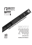
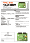
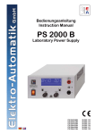
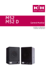
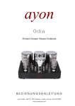
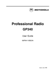
English/German
PALMER - PPB10
PRESS PATCH BOX
10 - Channel splitter
10 - Kanal Audiosignalverteiler
USER MANUAL
BEDIENUNGSANLEITUNG
AUFGABE
Eine Press Patch Box ist ein spezieller Audiosignalverteiler, der ein vorhandenes Ausgangssignal auf eine Vielzahl von Ausgängen
verteilt. Einen typischen Anwendungsfall stellt eine Pressekonferenz dar, wo Informationen durch einen Sprecher an viele Journalisten gerichtet werden. Damit nun nicht jeder der Medienvertreter sein individuelles Mikrofon aufbauen muß und es zu einem „Gerangel um die besten Plätze” kommt, kann das Signal eines einzigen Mikrofons über die Palmer Press Patch Box auf eine Vielzahl von
Ausgängen entsprechend verteilt werden.
AUSSTATTUNG
Die PPB10 besitzt einen trafosymmetrischen Eingang für Linesignale. Mechanisch ist er als XLR/f Buchse sowohl auf der Frontseite
wie auch auf der Rückseite vorhanden. Eine parallele Benutzung wird nicht empfohlen. Neben der rückwärtigen Buchse beÞndet
sich ein Ground-Lift-Schalter, der den Pin 1 beider XLR-Buchsen von der Masse freischaltet. Über den Pegelsteller rechts neben
der frontseitigen Eingangsbuchse kann die Verstärkung von maximaler Dämpfung auf +25dB eingestellt werden. Eine 5-teilige
LED-Kette gibt Auskunft über die Höhe des Ausgangssignals. Bei 0dB Anzeige hat das Ausgangssignal einen Pegel von +6dBu
unbelastet, bei Abschluss mit 600 Ohm sinkt der Pegel auf +4dBu.
Die PPB 10 verfügt über 10 symmetrische Ausgänge, die mechanisch als XLR/m-Buchsen auf der Frontseite angeordnet sind. Alle
10 Ausgänge sind galvanisch durch Übertrager isoliert. Um eine Beeinßussung der Ausgänge untereinander auszuschließen, wird
für jeweils ein benachbartes Paar eine sehr niederohmige Treiberschaltung eingesetzt, die einen Ausgangsübertrager mit zweifacher Splitwicklung speist. Gegeneinander wird ein solches Ausgangspaar mit Widerständen entkoppelt. Im Kurzschlussfall eines
Ausgangs wird daher allenfalls ein Nachbarkanal um ca. 3dB gedämpft, alle übrigen Ausgänge bleiben absolut unbeeinßusst. Die
Ausgänge können individuell über einen GND-Lift-Schalter, der sich auf der Rückseite beÞndet, erdfrei geschaltet werden.
PPB10 KASKADIEREN
Um die Anzahl von Ausgangskanälen zu erweitern, können mehrere PPB10 miteinander kombiniert werden. Dazu dienen die rückseitigen BUS IN/BUS OUT Buchsen. Vom „Master“, also dem Gerät, das das Eingangssignal liefert, wird die BUS OUT Buchse mit
der BUS IN BUCHSE des zweiten Gerätes verbunden. An der BUS Out Buchse dieses Gerätes können Sie dann das nächste Gerät
anschließen. Benutzen Sie als Verbindungskabel ein abgeschirmtes Mono-Klinkenkabel. Die BUS OUT Buchse eines Gerätes kann
auch als zusätzlicher unsymmetrischer Ausgang genutzt werden. Bei 0dB Anzeige beträgt die Ausgangsspannung 0dBu.
KOPFHÖRER
Zur akustischen Überwachung des Eingangssignals ist ein Anschluss für Kopfhörer vorhanden. Die 6.3mm Stereobuchse auf der
Frontseite ist so verschaltet, dass sich ein Monosignal L/R auf beiden Kapseln ergibt. (Tip und Ring der Klinkenbuchse sind miteinander verschaltet). Falls Sie den Kopfhörerausgang anderweitig belegen, achten Sie unbedingt darauf, dass kein Monoklinkenstecker benutzt wird, da in diesem Fall über den Schaft des Steckers ein Teil der Ausgangsspannung kurzgeschlossen würde. Alle
Kopfhörer mit Impedanzen von 8 bis 200 Ohm können angeschlossen werden. Die Lautstärke lässt sich über das nebenan beÞndliche Potentiometer in weiten Grenzen einstellen.
STROMVERSORGUNG
Die PPB 10 wird über ein eingebautes Netzteil aus dem 230/240V Netz versorgt. Eine IEC Netzbuchse mit integriertem Sicherungshalter ist auf der Rückseite des Gehäuses vorhanden. Daneben beÞndet sich der Netzschalter. Eine rote LED auf der Frontseite
zeigt an, ob das Gerät eingeschaltet ist.
Zwischen Netzschalter und den individuellen Ground-Lift-Schaltern der Kanäle beÞndet sich ein weiterer horizontal angeordneter Erdungsschalter. Dieser Schalter verbindet/trennt die Elektronikmasse vom Gehäuse. Das Trennen der Elektronikmasse vom Gehäuse
beseitigt z.B. in 19“ Geräteschränken oft gefürchtete Masseschleifen. Der gelb/grüne Schutzleiter PE ist jedoch vorschriftsmäßig
immer mit dem Gehäuse verbunden.
TECHNISCHE DATEN
Eingänge:
Trafosymmetrisch für Linepegel, XLR/f Parallelbuchsen auf Front- und Rückseite mit Ground-Lift-Schalter, Nominelle Impedanz 10k
Ohm
Nomineller Eingangspegel: 0dbu, maximal +20dBu
Maximale Verstärkung zum Ausgang: 25dB
Ausgänge:
10 trafosymmetrische Ausgänge XLR/m mit GND-LIFT-Schalter
Nomineller Ausgangspegel +4dBu bei 600 Ohm Last und 0dB LED-Anzeige
Nominelle Ausgangsimpedanz: 300 Ohm
Kopfhörerausgang: 6.3mm Stereoklinke, Tip und Ring mono verschaltet
Für Kopfhörer von 8 bis 200 Ohm geeignet, Lautstärke kontinuierlich einstellbar.
5 stuÞge LED-Kette -12dB, -6dB, 0dB, +3dB, +6dB zur Überwachung des Ausgangspegels,
BUS- Ein- und Ausgang über Monoklinke zur Erweiterung der Anzahl der Ausgänge.
Stromversorgung 230/240VAC (andere auf Anfrage), max. Leistungsaufnahme 10 Watt.
Mechanisch:
19“-Stahlblechgehäuse 1 HE ca. 205mm tief, GEWICHT: 4Kg
PALMER - PPB10: User Manual
Page 2
KOMPONENTEN
7
2
3
5
4
1
6
11
9
8
10
12
13
14
01) Lineeingang
02) Pegelanzeige Ausgangspegel
03) Eingangspegelsteller
04) 10 Splitausgänge
05) Kopfhörerlautstärke
06) Kopfhörerausgang
07) Power LED
08) Netzstecker mit Sicherung
09) Netzschalter
10) Verbindet/trennt die elektronische Erde mit/von der Gehäuserde
11) Ground Lift Schalter für die Ausgänge
12) Bus verbindung um mehrere PPB10 oder PPB20 zu kaskadieren
13) Ground Lift für den Eingang
14) Paralleler Lineeingang
PALMER - PPB10: User Manual
Page 3
INTRODUCTION
The PPB10 is a special kind of audio splitter in that it splits one incoming signal up to twenty outputs (as opposed to the usual
three). This splitter is especially intended for press conferences, in which a speaker addresses a number of journalists. Instead of
each journalist having to place his or her own microphone in front of the speaker, the PPB10 splits up the signal of one microphone
up to twenty outputs.
FUNCTION
The PPB10 is comes with a transformer balanced input for line signals. Mechanically the input is equipped with Neutrik XLR/f
sockets on the front as well as on the rear of the device. We do not advise a simultaneous use of both inputs. A ground lift switch
is located next to the XLR input on the rear, this switch disconnects the pin 1 of both input XLRs from ground. You can adjust the
input gain with the gain pot next to the front XLR input, the gain ranges from -! to +25dB. The 5-segement LED meter helps you
monitor the output level. When this meter indicates 0dB the output level reads +6dBu without a load connected and +4dBu with a
load of 600Ohms.
The PPB10 offers 10 balanced outputs which are located on the front of the device in form of Neutrik XLR/m sockets. All 10 outputs
are galvanically isolated by the use of transformers. To avoid interferences between the individual channels , 5 low ohmic driver
circuits are used to drive 5 transformers, each of which split up the input signal to two outputs. The output pairs coming from each
transformer are decoupled from each other by the use of resistors. In case of a short circuit on an output, only one other channel will
be affected in that it is dampened by 3dB. All other channels remain completely unaffected. Each output has its individual ground
lift switch on the rear of the device.
CASCADING THE PPB10
To increase the number of output channels you can cascade numerous PPB10. For this application, the unit has been equipped with
BUS IN/BUS OUT connectors on the rear. Simply connect the BUS OUT of the Þrst device (which is connected to the source signal)
to the BUS IN of the second device. The BUS OUT of the second device can then be connected to the BUS IN of a third device and
so on. Use a shielded cable with mono jacks to make these connections. The BUS OUT can also be used as an 11th split output.
Here the output reads 0dBu when the meter on the front shows 0dB.
HEADPHONES
To acoustically monitor the input signal you can connect a pair of headphones to the PPB20. The ¼” TRS jack socket on the front is
connected in such a way, that the mono input signal can be heard equally on both sides of the headphones (the tip and ring of the
jack socket are connected together). Should you use this output for other purposes, make sure not to use a mono jack connector
since the shaft of the connector will short a part of the output voltage. All headphones with impedances from 8 to 200 Ohms can be
connected. The headphone volume can be adjusted via the volume pot next to the headphone connector.
POWER SUPPLY
The PPB10 is powered by an internal 230 Volt power supply. Power connector, fuse compartment and power switch can be found
on the rear of the device. A red LED on the front indicates that the device is turned on. A horizontally mounted ground switch is allocated between the power switch and the individual ground lift switches on the rear. The switch connects/disconnects the electronic
ground from the housing of the unit. A disconnection makes sense to avoid ground loop humming when the unit is Þtted into a 19”
rack together with other mains powered devices. The yellow/green PE grounding connector however remains connected according
to the regulations.
SPECIFICATIONS
Inputs
XLR/f parallel connectors on the front and rear - transformer balanced, ground lift switch. Nominal impedance 10kOhms
Nominal input level: 0dBu, max. +20dBu
Max. ampliÞcation to the outputs: 25dB
Outputs:
10 transformer-balanced outputs XLR/m with ground lift switch.
Nominal output level +4dBu at 600Ohms load and 0dB LED meter
Nominal output impedance: 300Ohms
Headphone output: 6,3mm (1/4”) stereo jack, tip and ring connected together
Suitable for headphones from 8 to 200Ohms, volume steplessly variable
5 segment LED chain: -12dB, -6dB, 0dB, +3dB, +6dB. To monitor the output level
Bus in and out via mono jack to connect several units
Power supply 230/240VAC, max power consumption 10Watts
Mechanical
19”, 1U Steel housing 205mm deep
Weight: 4Kg
PALMER - PPB10: User Manual
Page 4
COMPONENTS
7
2
3
5
4
1
6
11
9
8
10
12
13
14
01) Line input
02) 5 segment meter, output level
03) Input gain
04) 10 split outputs
05) Headphones volume
06) Headphone output
07) Power LED
08) Fuse and mains connector
09) Power switch
10) Connects electronic ground to chassis ground
11) Ground Lift switches for the outputs
12) Bus connections for linking numerous PPBs
13) Ground Lift for the inputs
14) Parallel line input
PALMER - PPB10: User Manual
Page 5
CURVE PLOTS
Frequency & Phase Response
Line Input to Output
Source: 0dBu/600 Ohms
Load: 200k Ohms
Total Harmonic Distortion (THD)
Line Input to Output
Source: 0dBu/600 Ohms
Output Level: +6dBu
PALMER - PPB10: User Manual
Page 6