1
M52
M52 D
Control Monitor
Installation und Bedienung
Installation and Operation
Contents
SAFETY INSTRUCTIONS ................................................................................................................................2
2 M52 CONNECTION AND OPERATION ........................................................................................................3
2.1 OPERATING VOLTAGE ........................................................................................................................................................ 3
2.2 ANALOGUE INPUT ............................................................................................................................................................. 3
2.3 POWER SWITCH ................................................................................................................................................................ 3
2.4 VOLUME KNOB.................................................................................................................................................................. 3
2.5 BATTERY CONNECTION DC 12-20 V ................................................................................................................................. 3
2.6 SAFETY FUSE .................................................................................................................................................................... 3
2.7 PLACEMENT AND MOUNTING ............................................................................................................................................. 3
3 M52D CONNECTION AND OPERATION......................................................................................................3
3.1
3.2
3.3
3.4
3.5
3.6
3.7
3.8
3.9
OPERATING VOLTAGE ....................................................................................................................................................... 3
INPUT SELECT .................................................................................................................................................................. 3
ANALOGUE INPUT ............................................................................................................................................................ 3
DIGITAL INPUT XLR / BNC .............................................................................................................................................. 4
POWER SWITCH ............................................................................................................................................................... 4
VOLUME KNOB................................................................................................................................................................. 4
BATTERY CONNECTION DC12–20V.................................................................................................................................. 4
SAFETY FUSE ................................................................................................................................................................... 4
PLACEMENT AND MOUNTING ............................................................................................................................................ 4
4 OPERATION ............................................................................................................................................5
4.1 ON/OFF SWITCH .............................................................................................................................................................. 5
4.2 MONITORING LOUDNESS ................................................................................................................................................... 5
5 WARRANTY INFORMATION .....................................................................................................................5
1
Safety Instructions
It is absolutely essential that you read these safety instructions carefully before connecting and using this K+H product. Your safety
depends on it. Furthermore, failure to follow these instructions voids the warranty.
To ensure safe operation for years to come, keep these instructions in a safe place for future reference. K+H has
manufactured this product in accordance with IEC 92 (SEC) 39 standards, then tested and delivered it in safe operating
condition. To maintain it in this condition, you must:
•
•
•
•
observe all safety instructions
use the product only as described herein
have any maintenance, repairs, or modifications performed only by K+H or other authorized personnel
ensure that the room in which you use this product is wired in accordance with the local electrical code
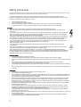
Warning!
•
When the interior of the cabinet is exposed, touching some parts can lead to an electric shock.
•
If you need to gain access to the interior electronics of the unit, always disconnect the unit from any and all power
sources first.
•
Any repairs, maintenance, or other service of the unit when its interior compartment is exposed may only be performed
safely (in accordance with VBG 4) by authorized technicians familiar with all the risks involved. Even in an unplugged
state, a fully charged capacitor in the unit can zap the unsuspecting.
•
Loudspeaker output jacks labelled with the IEC 417/5036 emblem (Fig. A) may be carrying dangerously high voltages. If
your unit has this emblem, ensure that any connections to be made between these jacks and the speakers themselves
are made before powering up the unit, and are done so only with manufacturer-approved interconnecting cables.
If you need to replace any fuses, ensure that the replacements are of exactly the same type, value and voltage as the
•
originals, as spelled out in the technical specifications at the rear of this manual.
•
Do not use "repaired" fuses.
•
If you do not have fuses of the specified size, type and value, do not hot-wire the contacts in the holder by shortcircuiting them.
•
Certain areas of the cabinet, cover, and rear panel can achieve extreme temperatures and are therefore marked with a
"HOT" label (Fig. B). Refrain from touching any heat sink or ventilation grille.
•
High volume levels are known to cause permanent - i.e. irreversible - hearing damage, especially when listened to
without sufficient breaks. The higher the levels, the more frequent and extended must be the breaks. Avoid standing too
close to loudspeakers that are being driven at high levels. If you must be exposed to high sound pressure levels over an
extended period of time, use hearing protection.
Fig. A
Fig. B
Mains Connection:
•
This unit is designed for continuous operation.
•
Ensure that the operating voltage of the unit matches that of the local mains current (AC line voltage).
•
Always check before connecting the power cable to the mains socket that the power switch on the unit itself is set to off
("O").
•
Use the power cable or power supply that came with the unit to connect to the mains socket (wall outlet).
•
Power supply: a damaged power cable may not be repaired. Use a new cable.
•
Avoid plugging the mains cable into a power strip that already has several other power-consuming devices connected to
it.
•
Avoid using extension cables. The unit must be connected to a mains socket close to it, and that socket should be freely
accessible.
Installation:
•
This product may only be placed on a stable, clean, horizontal surface.
•
Do not expose this product to vibration.
•
Do not operate this product anywhere near water or other liquids. Do not use it near a sink, swimming pool, bathtub, or
in any damp room or area. Electrical shocks carried through water can kill. Do not place any beverages whatsoever on or
near this product, as liquids can kill electronic components.
•
Ensure sufficient ventilation around the product to allow for adequate heat dissipation, especially near the rear panel
and the sides of the cabinet (minimum of 8 inches from the nearest wall). The unit may only be installed in a rack if
measures are taken to ensure sufficient ventilation and if the mounting instructions of the manufacturer are followed.
Do not block or cover any heat sink, fan, or vent.
•
Do not place the product where it will be in the path of direct sunlight, and keep it a safe distance away from radiators
and other heaters of any kind.
•
If you bring this product from a cold environment into a warm one (such as from a vehicle into a studio), it is quite
possible that condensation will form inside the cabinet. Please allow the unit sufficient time for acclimation to room
temperature (minimum thirty minutes) before connecting and powering up.
•
To avoid accidents, do not use any accessory equipment with this product that is not approved by the manufacturer,
particularly mounting accessories.
•
Do not place this unit on any unstable platform, cart, stand or table. If the unit falls, it can cause bodily injury to persons,
or can be damaged itself.
•
To protect this product from lightning damage during a thunderstorm or from power surges during an extended
absence, disconnect the power cable from the wall outlet.
2
2 M52 Connection and
Operation
2.1 Operating Voltage
The M52 control monitor has a built in power
supply which accepts line voltages between AC
85 - 230 Volt / 50-60 Hz and is compatible with
batteries having 12 – 20 Volt DC outputs.
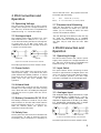
2.2 Analogue Input
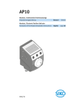
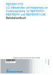
The analogue audio signal connects to a 3-pin
XLR wired with Pin 1 = GND, Pin 2 = +, Pin 3 = -,
via an internal floating transformer and requires
an input level of +6 dBu (1.55 Volts). For
unbalanced connections wire a jumper across pin
1 and pin 3 as shown below.
remove the back cover. Only replace fuses with
the proper type and rating:
AC
Battery
230 V
800 mA SB (5 x 20 mm)
12 –20 V 3150 mA SB (5 x 20 mm) internal
2.7 Placement and Mounting
Place the Mini Monitor so that the listening
distance is between 0.5 meters (1.5’) and 1.5
meters (5’). For listening to stereo turn both
monitors in toward the listener.
The 3/8“ bushing on the bottom of the unit may
be used for attachment to a standard
microphone stand. The M6 attachment points on
the sides may be used with the LH11 table
stand.
3 M52D Connection and
Operation
3.1 Operating Voltage
The audio input level must never exceed 7 Volts.
The M52 D control monitor has a built in power
supply which accepts line voltages between AC
85 - 230 Volt / 50-60 Hz and is compatible with
batteries having 12 – 20 Volt DC outputs.
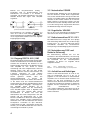
2.3 Power Switch
3.2 Input Select
The switch on the back of the unit turns on the
internal power supply. A red LED on the front
panel indicates the standby condition. A second
switch built into the volume knob on the front
panel turns the unit from standby into
operation.
The inputs selector allows monitoring of either
the left or right channels of a digital input or the
mono sum of the left and right digital channels.
In the analogue position, the XLR input
connector is changed over to an analogue input.
unbalanced
balanced
as seen from the solder terminals of the male XLR
2.4 Volume Knob
The volume knob is used to turn the unit from
standby to on and to adjust the audio listening
level. When the unit is in standby the LED glows
red and then turns to green when the unit is
operating.
2.5 Battery Connection DC 12-20 V
The battery connection is made to a 4 pin male
XLR connector on the back side. Please observe
the correct polarity wth Pin 4 = 12-20V, Pin 1 =
GND. An internal diode will protect the
electronics if wired incorrectly.
3.3 Analogue Input
The analogue audio signal connects to a 3-pin
XLR wired with Pin 1 = GND, Pin 2 = +, Pin 3 =
-, via an internal floating transformer and
requires an input level of +6 dBu (1.55 Volts).
For unbalanced connections wire a jumper
across pin 1 and pin 3 as shown below.
2.6 Safety Fuse
The AC power fuse can be found on the back side
of the monitor. In order to access the fuse for
the battery power connection it is necessary to
unbalanced
balanced
as seen from the solder terminals of the male XLR
The audio input level must never exceed 7 Volts.
3
Important: The BNC selector switch must be set
to 75 ohm termination (3rd position from the
left) when not using a digital input.
3.8 Safety Fuse
The AC power fuse can be found on the back side
of the monitor. In order to access the fuse for
the battery power connection it is necessary to
remove the back cover. Only replace fuses with
the following type and rating:
Netz
Battery
230 V
800 mA SB (5 x 20 mm)
12 –20 V 3150 mA SB (5 x 20 mm) internal
3.9 Placement and Mounting
3.4 Digital Input XLR / BNC
Place the Mini Monitor so that the listening
distance is between 0.5 meters (1.5’) and 1.5
meters (5’). For listening to stereo turn both
monitors in toward the listener.
The AES digital signal contains two audio
channels being transmitted in one cable. The left
and right channels may be selected individually
with the selector knob on the front panel of the
monitor. The AES digital connection to the XLR
input is point-to-point and may not be looped.
The 3/8“ bushing on the bottom of the unit may
be used for attachment to a standard
microphone stand. The M6 attachment points on
the sides may be used with the LH11 table
stand.
When using the AES 3id or SP-DIF connection
into the BNC it is possible to connect more mini
monitors by using T-connectors.
In this
configuration make sure that the 75 ohm
termination is switched off in all monitors except
for the last one in the chain.
When using a pair of monitors together it is
possible to connect them together via a BNC
cable. Feed the AES digital audio signal into the
first monitor. Set the selector switch next to the
BNC connector on the first monitor to the XLR
position. This setting changes the BNC to a
looping output from the XLR.
3.5 Power Switch
The switch on the back of the unit turns on the
internal power supply. A red LED on the front
panel indicates the standby condition. A second
switch built into the volume knob on the front
panel turns the unit from standby into
operation.
3.6 Volume Knob
The volume knob is used to turn the unit from
standby to on and to adjust the audio listening
level. When the unit is in standby the LED glows
red and then turns to green when the unit is
operating.
3.7 Battery Connection DC12–20V
The battery connection is made to a 4 pin male
XLR connector on the back side. Please observe
the correct polarity wth Pin 4 = 12-20V, Pin 1 =
GND. An internal diode will protect the
electronics if wired incorrectly.
4
4 Operation
4.1 On/Off Switch
Turn on the master power switch on the back of
the unit. Turn the volume knob clockwise until
the monitor changes from the standby condition
to the operating condition. The LED on the front
panel will glow red in standby mode will change
to green when the unit is operating.
4.2 Monitoring Loudness
The M52(D) mini monitor is for listening at close
distances in the near field. It is best to avoid
excessive boosting of the high or low frequencies
to compensate for bad placement of the monitor
itself.
This monitor is capable of producing audio
listening levels that could cause hearing damage.
Care must be taken to adjust the monitor to a
proper level and to allow the ears adequate
resting time between listening sessions. Hearing
protection should be used when being exposed
to high sound levels for an extended period of
time.
5 Warranty Information
All K+H products undergo an extensive
procedure of quality control testing before
leaving the factory.
If you should ever need warranty service, put the
unit in its original packing material and carton
together with a detailed description of the
problem, and ship it (freight prepaid) to the
dealer where the unit was purchased.
K+H warrants that the product is free from any
defects in both material and manufacturing and
that it meets the specifications. Not covered
under this warranty are damages due to nonprofessional packing and shipment, wear and
tear, improper handling, improper installation,
improper operation or improper maintenance.
The limitation period for warranty claims is
described in the terms and conditions of K+H
mBH. It is our choice to repair, to supply a new
product or to withdraw from the contract.
In the event warranty service is requested,
presentation of a warranty card is not necessary.
Proof of purchase date can be made by filing
copies of appropriate documents (i.e. invoice or
delivery notice).
5
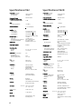
Specifications M52
Specifications M52D
Sound Level at 3 % THD
measured between
at 1 m distance
100 Hz und 6 kHz
100 dB/SPL
Sound Level at 3 % THD
measured between
at 1 m distance
100 Hz and 6 kHz
100 dB/SPL
Frequency Response
90 Hz bis 20 kHz
Frequency Response
90 Hz bis 20 kHz
± 5 dB
Free Field Frequency Variation
between 100 Hz and 20 kHz
± 5 dB
Free Field Frequency Variation
between 100 Hz and 20 kHz
Noise
Noise
at 10 cm (4”) distance
< 20 dB(A)
Harmonic Distortion
with 350 Hz at 1 m
< 1 % at 80 dB/SPL
Amplifier
Output Power
AC Connection
12 Volt Battery
20 Volt Battery
25 W 4 Ohm THD < 0,1 %
10 W 4 Ohm THD < 0,1 %
24 W 4 Ohm THD < 0,1 %
Analogue Input
Input Impedance
Input Level
Level Control (Front) continuous
Common Mode Rejection
transformer balanced, floating
> 10 kOhm
+ 6 dBu (1,55 V)
0 dB – negative infinity
to 15 kHz > 50 dB
Speaker Type
broadband 75mm (3”) Ø
Magnetically Shielded
standard
Power Connection
AC Mains
AC ~ 85 - 230 V 50 - 60 Hz
Battery
12 - 20 V DC
Power Draw
Idle, AC Mains Connection
At Full Output :
AC Mains Connections
Maximum Battery Draw
at 10 cm (4“) distance
< 20 dB(A)
Harmonic Distortion
with 350 Hz at 1 m
< 1 % at 80 dB/SPL
Amplifier
Output Power
AC Connection
12 Volt Battery
20 Volt Battery
25 W 4 Ohm THD < 0,1 %
10 W 4 Ohm THD < 0,1 %
24 W 4 Ohm THD < 0,1 %
Digital Circuit
Bit Depth
Sample Rate
256x Oversampling, ∆∑
24 Bit
32 - 96 kHz
Digital Input
AES/EBU
3-pin XLR female, 110 Ohm
transformer floating
BNC
75 Ohm unbalanced, switchable
AES 3id, S/P-DIF
Analogue Input
Input Impedance
Input Level
Level Control, continuous
Common Mode Rejection
transformer balanced, floating
> 10 kOhm
+ 6 dBu (1,55 V)
0 dB – negative infinity
to 15 kHz > 50 dB
Input Selection Knob
analog, digital left,
digital right, digital mono
Speaker Type
broadband 75mm (3”) Ø
Magnetically Shielded
standard
5W
50 W
20 V 2.0 A
Power Connection
Fuse
AC Mains
Battery
800 mA slow
3150 mA slow
Connectors
Audio Input
AC Mains
XLR 3-pin, female
Kaltgerätedose mit
Schutzkontakt
XLR 4-pin, male
Pin 4 = 12 .. 20V; Pin 1 GND
Battery
AC Mains
Battery
AC ~ 85 - 230 V 50 - 60 Hz
12 - 20 V DC
Power Draw
Idle, AC Mains Connection
At Full Output:
AC Mains Connections
Maximum Battery Draw
Fuse
AC Mains
Battery
7W
50 W
20 V 2.0 A
800 mA slow
3150 mA slow
Indicators
Standby
Operate
red LED on faceplate
green LED on faceplate
Housing
aluminum
coated RAL 7021
Mounting
3/8" threaded socket on bottom,
M6 points in the sides
Dimensions
WxHxD
120 x 173 x 116 mm
(4.7” x 6.8” x 4.6”)
Volume (gross)
2,4 liter (147 cu in)
Weight
1,7 kg (3.8 lbs)
Accessories
Table Stand LH 11 with
mounting screws
Connectors
Analogue / Digital Input
Digital Input / Output
AC Mains
Battery
Indicators
Standby
Operate
red LED on faceplate
green LED on faceplate
Housing
aluminium, coated RAL 7021
Mounting
3/8" threaded socket on bottom
M6 points in the sides
Dimensions
6
XLR 3-pin female
BNC
Kaltgerätedose mit
Schutzkontakt
XLR 4-in, male
Pin 4 = 12 .. 20V; Pin 1 GND
W x H x D 120 x 173 x 116 mm
(4.7“ x 6.8“ x 4.6“)
Volume (gross)
Weight
2,4 liter (147 cu in)
1,8 kg (4 lbs)
Accessories
Table Stand LH 11 with mounting
screws
Wichtige Sicherheitshinweise! .................................................................................................2
2 Anschluss und Inbetriebnahme M52 ...........................................................................................3
2.1 BETRIEBSSPANNUNG ......................................................................................................................................................... 3
2.2 NF-EINGANG INPUT ........................................................................................................................................................ 3
2.3 NETZSCHALTER POWER ................................................................................................................................................... 3
2.4 PEGELSTELLER VOLUME................................................................................................................................................... 3
2.5 BATTERIEANSCHLUSS DC 12-20 V ................................................................................................................................... 3
2.6 NETZSICHERUNG FUSE UND BATTERIE-SICHERUNG ............................................................................................................. 3
2.7 AUFSTELLEN UND BEFESTIGEN............................................................................................................................................ 3
3 Anschluss und Inbetriebnahme M52D ........................................................................................3
3.1
3.2
3.3
3.4
3.5
3.6
3.7
3.8
3.9
BETRIEBSSPANNUNG ........................................................................................................................................................ 3
EINGANGSWAHL SELECT................................................................................................................................................. 3
EINGANG INPUT ANALOG ............................................................................................................................................. 3
EINGANG DIGITAL XLR / BNC ....................................................................................................................................... 4
NETZSCHALTER POWER .................................................................................................................................................. 4
PEGELSTELLER VOLUME ................................................................................................................................................. 4
BATTERIEANSCHLUSS DC 12–20 V ................................................................................................................................. 4
NETZSICHERUNG FUSE UND BATTERIE-SICHERUNG ............................................................................................................ 4
AUFSTELLEN UND BEFESTIGEN........................................................................................................................................... 4
4 Bedienung..........................................................................................................................................5
4.1 EIN/AUS-SCHALTER....................................................................................................................................................... 5
4.2 ABHÖR-LAUTSTÄRKE ....................................................................................................................................................... 5
5 Garantie.............................................................................................................................................5
1
Wichtige Sicherheitshinweise!
•
Bitte vor Gebrauch lesen und für späteren Gebrauch
aufbewahren!
•
Das Gerät wurde von KLEIN+HUMMEL gemäß IEC
92 (sec) 39 gebaut und hat unser Werk in
sicherheitstechnisch einwandfreiem Zustand
verlassen. Um diesen Zustand zu erhalten und
einen gefahrlosen Betrieb sicherzustellen, muss
der Anwender die Hinweise und Warnvermerke
beachten, die in der Bedienungsanleitung
enthalten sind. Das Gerät entspricht der
Schutzklasse I (schutzgeerdet).
Die Sicherheit, Zuverlässigkeit und Leistung des Gerätes wird
von KLEIN+HUMMEL nur dann gewährleistet, wenn:
•
Montage, Erweiterung, Neuinstallation, Änderungen
oder Reparaturen von KLEIN+HUMMEL oder dazu
ermächtigten Personen ausgeführt werden.
•
die elektrische Installation des betreffenden Raumes
den Anforderungen von IEC (ANSI)-Festlegungen
entspricht.
•
das
Gerät
in
Übereinstimmung
mit
der
Gebrauchsanweisung verwendet wird.
Warnung!
•
Wenn Abdeckungen geöffnet oder Gehäuseteile
entfernt werden, außer wenn dies von Hand möglich ist,
können Teile freigelegt werden, die Spannung führen.
•
Wenn ein Öffnen des Gerätes erforderlich ist, muss das
Gerät von allen Spannungsquellen getrennt sein.
Berücksichtigen Sie dies vor dem Abgleich, vor einer
Wartung, vor einer Instandsetzung und vor einem
Austausch von Teilen.
•
Ein Abgleich, eine Wartung oder eine Reparatur am
geöffneten Gerät unter Spannung darf nur durch eine
vom Hersteller autorisierte Fachkraft (nach VBG 4)
geschehen, die mit den verbundenen Gefahren vertraut
ist. Lautsprecherausgänge, die mit dem IEC 417 /
5036-Zeichen (Abb. 1 s. unten) versehen sind, können
berührungsgefährliche Spannungen führen. Deshalb vor
dem Einschalten des Gerätes Verbindungen mit dem
vom Hersteller empfohlenen Anschlusskabel zum
Lautsprecher herstellen.
•
Alle Stecker an Verbindungskabeln müssen mit dem
Gehäuse verschraubt oder verriegelt sein, sofern
möglich.
•
Es dürfen nur Sicherungen vom angegebenen Typ und
der angegebenen Nennstromstärke als Ersatz
verwendet werden.
•
Eine Verwendung von geflickten Sicherungen oder
Kurzschließen des Halters ist unzulässig.
•
Niemals die Schutzleiterverbindung unterbrechen.
•
Oberflächen, die mit dem “HOT”-Zeichen (Abb. 2 s.
unten) versehen sind, Rückwände oder Abdeckungen
mit Kühlschlitzen, Kühlkörper und deren Abdeckungen,
sowie Röhren und deren Abdeckungen können im
Betrieb erhöhte Temperaturen annehmen und sollten
deshalb nicht berührt werden.
•
Hohe Lautstärkepegel können dauernde Gehörschäden
verursachen. Vermeiden Sie deshalb die direkte Nähe
von Lautsprechern, die mit hohen Pegeln betrieben
werden. Verwenden Sie einen Gehörschutz bei
dauernder Einwirkung hoher Pegel.
Netzanschluss:
•
Das Gerät ist für Dauerbetrieb ausgelegt.
•
Die eingestellte Betriebsspannung muss mit der
örtlichen Netzspannung übereinstimmen.
•
Achtung: Der Netzschalter des Gerätes muss in 0 Position stehen, wenn das Netzkabel angeschlossen
wird.
2
•
•
Der Anschluss an das Stromnetz erfolgt mit dem
mitgelieferten Netzteil oder Netzkabel.
Netzteil: Eine beschädigte Anschlussleitung darf nicht
repariert werden.
Vermeiden Sie einen Anschluss an das Stromnetz in
Mehrfachsteckdosen
zusammen
mit
anderen
Stromverbrauchern.
Die Steckdose für die Stromversorgung muss nahe am
Gerät angebracht und leicht zugänglich sein.
Aufstellungsort:
•
Das Gerät sollte nur auf einer sauberen, waagerechten
Arbeitsfläche stehen.
•
Das Gerät darf während des Betriebes keinen
Erschütterungen ausgesetzt sein.
•
Feuchtigkeit und Staub sind nach Möglichkeit
fernzuhalten.
•
Das Gerät darf nicht in der Nähe von Wasser,
Badewanne, Waschbecken, Küchenspüle, Nassraum,
Swimmingpool oder feuchten Räumen betrieben
werden. Keine mit Flüssigkeit gefüllten Gegenstände Vase, Gläser, Flaschen etc. auf das Gerät stellen.
•
Sorgen Sie für ausreichende Belüftung der Geräte
•
Eventuelle Ventilationsöffnungen dürfen niemals
blockiert oder abgedeckt werden. Das Gerät muss
mindestens 20 cm von Wänden entfernt aufgestellt
werden. Das Gerät darf nur dann in ein Rack eingebaut
werden, wenn für ausreichende Ventilation gesorgt ist
und die Einbauanweisungen des Herstellers eingehalten
werden.
•
Vermeiden Sie direkte Sonneneinstrahlung sowie die
unmittelbare Nähe von Heizkörpern und Heizstrahlern
oder ähnlichen Geräten.
•
Wenn das Gerät plötzlich von einem kalten an einen
warmen Ort gebracht wird, kann sich im Geräteinnern
Kondensfeuchtigkeit bilden. Vor dem Einschalten
solange warten, bis das Gerät Raumtemperatur
angenommen hat.
•
Zubehör: Das Gerät nicht auf einen instabilen Wagen,
Ständer, Dreifuß, Untersatz oder Tisch stellen. Wenn das
Gerät
herunterfällt, kann es Personenschäden
verursachen und selbst beschädigt werden. Verwenden
Sie das Gerät nur mit einem vom Hersteller
empfohlenen oder zusammen mit dem Gerät
verkauften Wagen, Rack, Ständer, Dreifuß, Untersatz
oder sonstigen Befestigungs- oder Flugmaterial. Bei der
Aufstellung des Gerätes müssen die Anweisungen des
Herstellers befolgt und muss das vom Hersteller
empfohlene Aufstellzubehör verwendet werden. Eine
Kombination aus Gerät und Gestell muss vorsichtig
bewegt werden. Plötzliches Anhalten, übermäßige
Kraftanwendung und ungleichmäßige Böden können
das Umkippen der Kombination aus Gerät und Gestell
bewirken.
•
Zusatzvorrichtungen:
Verwenden
Sie
niemals
Zusatzvorrichtungen, die nicht vom Hersteller
empfohlen wurden, weil dadurch Unfälle verursacht
werden können.
•
Zum Schutz des Gerätes bei Gewitter oder wenn es
längere Zeit nicht beaufsichtigt oder benutzt wird,
sollte der Netzstecker gezogen werden. Dies
verhindert Schäden am Gerät aufgrund von
Blitzschlag
und
Spannungsstößen
im
Wechselstromnetz.
Abbildung 1
Abbildung 2
2 Anschluss und
Inbetriebnahme M52
2.1 Betriebsspannung
Der im Kontrollmonitor M 52 eingebaute
Verstärker ist für eine Netzspannung zwischen
AC 85 - 230 Volt / 50-60 Hz und für BatterieSpeisung mit 12 – 20 Volt DC ausgelegt.
Die Netzsicherung befindet sich auf der
Rückseite in der Netzkombination, die Sicherung
für den Batterieanschluss ist nur nach Abnahme
der Rückwand auf der Verstärkerplatine
zugänglich. Es dürfen nur folgende Werte
eingesetzt werden:
Netz
Batterie
2.2 NF-Eingang INPUT
Der trafosymmetrische, erdfreie Eingang des
Verstärkers ist mit einer 3poligen Gerätebuchse
nach XLR-Norm ausgerüstet. Die Empfindlichkeit
beträgt +6 dBu (1,55 V). Der eingebaute
Übertrager
gewährleistet
eine
Unsymmetriedämpfung von mindestens 50 dB
bei einer Eingangsimpedanz von 10 kOhm. Bei
unsymmetrischen Tonquellen wird im AnschlussStecker eine Drahtbrücke von Kontakt 1 zu
Kontakt 3 eingelötet.
unsymmmetrisch
2.6 Netzsicherung FUSE und
Batterie-Sicherung
symmetrisch
jeweils auf Lötseite des Gegensteckers gesehen
Mit dem Pegelsteller (Volume) des MINIMONITORS M 52 wird die Lautstärke an der Front
eingestellt. Die Einspeisung von NF-Pegeln von
mehr als 7 Volt ist nicht zulässig.
2.3 Netzschalter POWER
Der Netzschalter befindet sich auf der Rückseite
des Mini Monitors. Sobald dieser eingeschaltet
wird, ist das Schaltnetzteil versorgt und der Mini
Monitor im Standby Modus. Die Betriebsanzeige
leuchtet rot. Ein zweiter Schalter ist im VolumeRegler auf der Front integriert. Mit diesem
Schalter wird der Mini Monitor aus dem Standby
Modus oder wenn er mit DC versorgt wird,
eingeschaltet. Die Farbe der Betriebsanzeige
wechselt auf grün.
250 V
12 V
800 mA träge (5 x 20 mm)
3150 mA träge (5 x 20 mm) intern
2.7 Aufstellen und Befestigen
Stellen Sie den MINI-MONITOR M 52 so auf, dass
ein Hörabstand von 0,5 m bis 1,5 m gegeben ist.
Für das Abhören im Stereo-Betrieb empfiehlt
sich ein Drehen beider Gehäuse zum Zuhörer hin.
Bei einer Aufstellung vor einer Wand ist durch
die Anschluss-Armaturen der für die Kühlung
erforderliche Abstand zur Rückseite gegeben.
Auf der Unterseite des Gehäuses ist eine
Gewindebuchse für 3/8"- Stative angebracht.
Somit lässt sich der M 52 bequem auf alle
gebräuchlichen Mikrofon-Stative aufsetzen.
3 Anschluss und
Inbetriebnahme M52D
3.1 Betriebsspannung
Der im Kontrollmonitor M 52D eingebaute
Verstärker ist für eine Netzspannung zwischen
AC 85 - 230 Volt / 50-60 Hz und für BatterieSpeisung mit 12 – 20 Volt DC ausgelegt.
3.2 Eingangswahl SELECT
Der
Eingangswahlschalter
bestimmt
die
eingangsseitige Betriebsart. Analogbetrieb,
Digitalbetrieb auf linkem Kanal, Digitalbetrieb
auf rechtem Kanal sowie Digitalbetrieb mit der
Summe aus linkem und rechtem Kanal sind
wählbar.
2.4 Pegelsteller VOLUME
Der an der Front angeordnete Lautstärke-Steller
lässt sich bis auf minus unendlich einstellen.
2.5 Batterieanschluss DC 12-20 V
Der Batterieanschluss erfolgt über eine 4-polige
XLR Verbindung. Bitte achten Sie auf die richtige
Polung, Pin4 + 12-20V, Pin1 GND. Eine interne
Schutzdiode verhindert bei versehentlicher
Falschpolung eine Beschädigung des Verstärkers.
3.3 Eingang INPUT ANALOG
Der trafosymmetrische, erdfreie Eingang des
Verstärkers ist mit einer 3-poligen Gerätebuchse
nach XLR-Norm ausgerüstet. Die Empfindlichkeit
beträgt +6 dBu (1,55 V). Der eingebaute
Übertrager
gewährleistet
eine
Unsymmetriedämpfung von mindestens 50 dB
bei einer Eingangsimpedanz von 10 kOhm. Zum
3
Betrieb mit unsymmetrischen Analog Tonquellen wird im Anschlussstecker eine
Drahtbrücke von Kontakt 1 zu Kontakt 3
eingelötet. Bei digitaler Betriebsart wird über
dieselbe Buchse das Signal nach AES/EBU
zugeführt.
unsymmetrisch
symmetrisch
jeweils auf Lötseite des Gegensteckers gesehen
Die Einspeisung von analogen NF-Pegeln von
mehr als 7 Volt ist nicht zulässig. Wichtig: der
Abschlusswiderstand am digitalen BNC - Eingang
muss eingeschaltet werden wenn kein digitales
Eingangssignal anliegt.
3.5 Netzschalter POWER
Der Netzschalter befindet sich auf der Rückseite
des Mini Monitors. Sobald dieser eingeschaltet
wird, ist das Schaltnetzteil versorgt und der Mini
Monitor im Standby Modus. Die Betriebsanzeige
leuchtet rot. Ein zweiter Schalter ist im VolumeRegler integriert. Mit diesem Schalter wird der
Mini Monitor aus dem Standby Modus oder wenn
er mit DC versorgt wird, eingeschaltet. Die Farbe
der Betriebsanzeige wechselt auf grün.
3.6 Pegelsteller VOLUME
Der an der Front angeordnete Lautstärkesteller
lässt sich bis auf minus unendlich einstellen.
3.7 Batterieanschluss DC 12–20 V
Der Batterieanschluss erfolgt über eine 4polige
XLR Verbindung. Bitte achten Sie auf die richtige
Polung, Pin4 + 12 - 20V, Pin1 GND. Eine interne
Schutzdiode verhindert bei versehentlicher
Falschpolung eine Beschädigung des Verstärkers.
3.8 Netzsicherung FUSE und
Batterie-Sicherung
3.4 Eingang DIGITAL XLR / BNC
Der digitale Eingang umfasst beide Stereokanäle.
Auf der Frontseite lässt sich mittels des SELECT Schalters die Zuordnung des Monitors zu den
beiden Kanälen bestimmen. Die digitale Leitung
nach AES/EBU ist eine Punkt zu Punkt
Verbindung und intern abgeschlossen. Wird ein
digitales Signal nach AES 3id oder SP-DIF
verwendet, können mehrere Mini-Monitore mit
T-Stücken verbunden an
eine digitale
Signalleitung angeschlossen werden. Es muss
darauf
geachtet
werden,
dass
die
Abschlusswiderstände
in
diesem
Fall
ausgeschaltet sind. Nur am letzten Mini Monitor
in der Kette muss der Abschlusswiderstand
eingeschaltet sein. Da sich die BNC Buchse direkt
hinter dem digitalen Eingangs - Übertrager für
das AES/EBU Signal befindet, ist es
eingeschränkt möglich auch bei Verwendung
eines AES/EBU Signals einen 2. digitalen Mini
Monitor über eine einfache BNC Leitung
anzuschließen. In diesem Fall wird der
Wahlschalter des ersten Lautsprechers auf XLR
gestellt und der Wahlschalter des 2. Mini
Monitors auf BNC ohne Abschluss. Da das digitale
Signal nach AES/EBU große Pegeltoleranzen
aufweisen kann und kein Abschluss am letzten
Lautsprecher vorhanden ist (der Abschluss
erfolgt bereits am XLR - Eingang des ersten Mini
Monitor), ist die Betriebsicherheit einer solchen
Verbindung im Einzelfall zu prüfen.
4
Die Netzsicherung befindet sich auf der
Rückseite in der Netzkombination, die Sicherung
für den Batterieanschluss ist nur nach Abnahme
der Rückwand auf der Verstärkerplatine
zugänglich. Es dürfen nur folgende Werte
eingesetzt werden:
Netz
Batterie
230 V 800 mA träge (5 x 20 mm)
12 –20 V3150 mA träge (5 x 20 mm) intern
3.9 Aufstellen und Befestigen
Stellen Sie den Kontrollmonitor M 52 D so auf,
dass ein Hörabstand von 0,5 m bis 1,5 m
gegeben ist. Für das Abhören im Stereo-Betrieb
empfiehlt sich ein Drehen beider Gehäuse zum
Zuhörer hin. Bei einer Aufstellung vor einer
Wand ist durch die Anschluss-Armaturen der für
die Kühlung erforderliche Abstand zur Rückseite
gegeben. Auf der Unterseite des Gehäuses ist
eine
Gewindebuchse
für
3/8"- Stative angebracht. Somit lässt sich der M
52 D bequem auf alle gebräuchlichen MikrofonStative aufsetzen.
4 Bedienung
4.1 EIN/AUS-Schalter
Im Netzbetrieb wird der Mini Monitor M52 (D)
zunächst mit dem Netzschalter in der
rückseitigen Netzkombi-Einheit in den Standby
Modus geschaltet. Die frontseitige LED leuchtet
rot, bis der Verstärker mit dem frontseitigen
Dreh-Schalter eingeschaltet wird indem der
Volume-Regler aus der Off Position gedreht wird.
Die Betriebsanzeige wechselt von rot auf grün.
Der frontseitige Drehschalter ist sowohl bei Netzals auch bei Batterie-Betrieb in Funktion.
4.2 Abhör-Lautstärke
Der MINI-MONITOR M52 (D) ist für das Hören im
Nahfeld bestimmt. Es wird im Interesse der
Betriebssicherheit
davon
abgeraten,
bei
ungünstiger
Aufstellung
oder
größerem
Hörabstand das NF-Signal extern durch starkes
Anheben von Tiefen oder Höhen zu beeinflussen.
5 Garantie
Alle KLEIN + HUMMEL Produkte durchlaufen vor
dem Versand umfangreiche Qualitätskontrollen.
An die eingebauten Halbleiter werden extrem
strenge Prüfanforderungen gestellt. Für jeden
Lautsprecher wird die strikte Einhaltung der
technischen
Daten
innerhalb
üblicher
Serientoleranzen garantiert.
Zur Inanspruchnahme der Garantie ist der
Lautsprecher in der Original-Verpackung
kostenfrei, zusammen mit einem Fehlerbericht
an unseren Vertragspartner, bei dem das Gerät
gekauft wurde.
Auf alle Bauteile des Verstärkers wird eine
Garantie von 24 Monaten geleistet. Teile werden
kostenlos
ersetzt,
wenn
diese
einen
Materialfehler aufweisen und die Schäden nicht
durch unsachgemäße Behandlung, Bedienungsoder Montagefehler, Netzüberspannung oder
Nichtbeachtung
von
Anpassungsund
Betriebsvorschriften hervorgerufen wurde.
Die Vorlage einer besonderen Garantiekarte
entfällt. Durch geeignete Unterlagen (Rechnung,
Quittung, Lieferschein) ist das Kaufdatum
nachzuweisen.
5
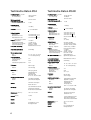
Technische Daten M52
Technische Daten M52D
Schalldruck-Pegel bei 3 % THD
gemittelt zwischen
in 1 m Entfernung
100 Hz und 6 kHz
100 dB/SPL
Schalldruck-Pegel bei 3 % THD
gemittelt zwischen
in 1 m Entfernung
100 Hz und 6 kHz
100 dB/SPL
Übertragungsbereich
90 Hz bis 20 kHz
Übertragungsbereich
90 Hz bis 20 kHz
Freifeld-Übertragungsmaß
zwischen 100 Hz und 20 kHz
± 5 dB
Freifeld-Übertragungsmaß
zwischen 100 Hz und 20 kHz
± 5 dB
Eigenstörgeräusch
Eigenstörgeräusch
in 10 cm Abstand
Klirrfaktor
über 350 Hz in 1 m
in 10 cm Abstand
< 20 dB(A)
< 1 % bei 80 dB/SPL
Elektronik/Endstufe
Ausgangsleistung
Netz-Betrieb
Batteriebetrieb 12 Volt
Batteriebetrieb 20 Volt
25 W 4 Ohm THD < 0,1 %
10 W 4 Ohm THD < 0,1 %
24 W 4 Ohm THD < 0,1 %
Eingang trafosymmetrisch, erdfrei
Eingangsimpedanz
Eingangsempfindlichkeit
Pegelsteller (Front) stufenlos
Unsymmetriedämpfung
> 10 kOhm
+ 6 dBu (1,55 V)
0 dB bis - unendlich
bis 15 kHz > 50 dB
Lautsprecher-Bestückung
Breitband-Chassis 75mm Ø
Magnetische Abschirmung
serienmäßig
Versorgungsspannungen
Netz
Batterie
Leistungsaufnahme
Leerlauf Netzbetrieb
Vollaussteuerung
Netzbetrieb
Vollaussteuerung Batterie 20 V
Sicherungen
Netz
Batterie
Anschlüsse
NF-Eingang
Netz
Batterie
AC ~ 85 - 230 V 50 - 60 Hz
12 - 20 V Gleichspannung
5W
50 W
2,0 A
800 mA träge
3150 mA träge
XLR 3-polig, female
Kaltgerätedose mit
Schutzkontakt
XLR 4-polig, male
Pin 4 = 12 .. 20V; Pin 1 GND
Anzeige Betriebsbereitschaft
Standby
Betrieb
rote LED auf Frontplatte
grüne LED auf Frontplatte
Gehäuse
Aluminium schwarzgrau
lackiert RAL 7021
Befestigung
3/8" Gewindebuchse auf der
Unterseite des Gehäuses,
M6 Gewinde in Seitenwänden
Abmessungen (B x H x T)
120 x 173 x 116 mm
Volumen (brutto)
2,4 Liter
Gewicht
1,7 kg
Zubehör
Tischständer LH 11 mit
Montageschrauben
6
< 20 dB(A)
Klirrfaktor
über 350 Hz in 1 m
< 1 % bei 80 dB/SPL
Elektronik/Endstufe
Ausgangsleistung
Netz-Betrieb
Batteriebetrieb 12 Volt
Batteriebetrieb 20 Volt
25 W 4 Ohm THD < 0,1 %
10 W 4 Ohm THD < 0,1 %
24 W 4 Ohm THD < 0,1 %
Digitalwandler
Wortbreite
Abtastrate
256-fach Oversampling, ∆∑
24 Bit
32 - 96 kHz,
Digitaler Eingang
XLR-3 fem
Eingangs - Impedanz
BNC – Buchse
Eingangs - Impedanz
nach Norm AES/EBU.
110 Ohm trafosym. Erdfrei
nach Norm AES 3id, S/P-DIF
75 Ohm unsym., schaltbar
Eingang
Eingangsimpedanz
Eingangsempfindlichkeit
Pegelsteller (Front) stufenlos
Unsymmetriedämpfung
trafosymmetrisch, erdfrei
> 10 kOhm
+ 6 dBu (1,55 V)
0 dB bis - unendlich
bis 15 kHz > 50 dB
NF – Quelle umschaltbar
wählbar mit Stufenschalter
analog, digital links,
digital rechts, digital mono
Lautsprecherbestückung
Breitbandchassis 75mm Ø
Magnetische Abschirmung
serienmäßig
Versorgungsspannungen
Netz
AC ~ 85 - 230 V 50 - 60 Hz
Batterie
12 - 20 V Gleichspannung
Leistungsaufnahme
Im Leerlauf Netzbetrieb
Bei Vollaussteuerung
Netzbetrieb
Batteriebetrieb
50 W
20 V 2,0 A
Sicherungen
Netz
Batterie
800 mA träge
3150 mA träge
Anschlüsse Audio-Signal
XLR3 Buchse 3-polig fem.
BNC Buchse:
Netz
Batterie
7W
analog/digital umschaltbar
digital Ein- / Ausgang
Kaltgerätedose mit
Schutzkontakt
XLR 4-polig, male
Pin 4 = 12 .. 20V; Pin 1 GND
Anzeige Betriebsbereitschaft
Standby
Betrieb
rote LED auf Frontplatte
grüne LED auf Frontplatte
Gehäuse
Aluminium schwarzgrau
lackiert RAL 7021
Befestigung
3/8" Gewindebuchse auf der
Unterseite des Gehäuses,
M6 Gewinde in Seitenwänden
Abmessungen B x H x T
Volumen (brutto)
Gewicht
120 x 173 x 116 mm
2,4 l
1,8 kg
Zubehör
LH 11 Tischständer mit
Montageschrauben
K+H Vertriebs- und Entwicklungsgesellschaft mbH
30900 Wedemark, Germany
Tel. +49 (5130) 58 48 0
Fax +49 (5130) 58 48 11
www.klein-hummel.de
www.klein-hummel.com
Printed 08/06
520766