1
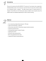
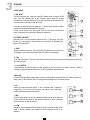
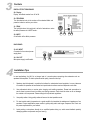
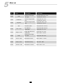
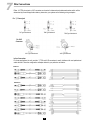
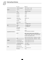
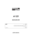
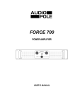
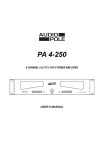
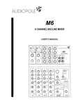
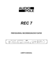
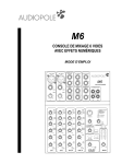
M12 12 CHANNEL MIC/LINE MIXER USER’S MANUAL Important Safety Instructions This symbol, wherever used, alerts you to the presence of un-insulated and dangerous voltages within the product enclosure. These are voltages that may be sufficient to constitute the risk of electric shock or death. This symbol, wherever used, alerts you to important operating and maintenance instructions POWER SUPPLY Ensure that the insource voltage (AC outlet) matches the voltage rating of the product. Failure to do so could result in damage to the product and possibly the user. Unplug the product before electrical storms occur and when unused for long periods of time to reduce the risk of electric shock or fire. EXTERNAL CONNECTION Always use proper ready-made insulated mains cabling (power cord). Failure to do so could result in shock/ death or fire. If in doubt, seek advice from a registered electrician. DO NOT REMOVE ANY COVERS Within the product are areas where high voltages may present. To reduce the risk of electric shock do not remove any covers unless the AC mains power cord is removed. Covers should be removed by qualified service personnel only. No user serviceable parts inside. FUSE To prevent fire and damage to the product, use only the recommended fuse type as indicated in this manual. Do not short-circuit the fuse holder. Before replacing the fuse, make sure that the product is OFF and disconnected from the ACD outlet. PROTECTIVE GROUND Before turning the unit on, make sure that it is connected to Ground. This is to prevent the risk of electric shock. Never cut internal or external Ground wires. Like wise, never remove Ground wiring from the Protective Ground Terminal. OPERATING SAFETY INSTRUCTIONS Read these instructions. Follow all instructions. Keep these instructions. Do not discard. Heed all warnings. Only use attachments/accessories specified by the manufacturer. POWER CORD AND PLUG Do not tamper with the power cord or plug. These are designed for your safety. Do not remove Ground connections! If the plug does not fit your AC outlet seek advice from a qualified electrician. Protect the power cord and plug from any physical stress to avoid risk o electric shock. Do not place heavy objects on the power cord. This could cause electric shock or fire? SERVICING Refer all servicing to qualified service personnel only. Do not perform any servicing then those instructions contained within this User’s Manual DISPOSAL This symbol indicates that the disposal of this product is submitted to local regulations. Please contact your local dealer. 2 Index 1. Introduction ……………………………………………………………………….. 4 2. Features ..…………………………………………………………………… 4 3. Controls ………………..………………………………………………………….. 5 4. Installation Tips …………………………………………………………………… 8 5. Preset List……………………………………………………….……...…………. 9 6. Hookup Diagram………………………………………………………………….. 10 7. Wire Connections ……………………………………………………………….… 11 8. Technical Specifications………………………………………….…………..…… 12 9. Block Diagram ………………………………………………………………..…… 13 10. Warranty …………………………………………………………………………… 14 11. Notes ……………………………………………………………………………….. 15 3 1 Introduction Thank you for the purchase of the M12 AUDIOPOLE. This mixer has 12 input channels and is equipped with a 24-bit digital effects processor. It has 4 microphone inputs and 4 stereo line inputs and is particularly suitable for live applications, studio or multimedia. The effects processor features 100 presets grouped into 10 categories. A 3-band EQ and a +48 V Phantom power supply are available for each microphone channel. Two separate outputs can be addressed independently for the main mix and the monitoring. 2 Features • 4 mono inputs with gold plated XLR and balanced ¼’’ TRS Jacks, • 4 stereo inputs with balanced ¼’’ TRS Jacks, • Ultra low noise pre-amp with 48 V Phantom power supply for electret microphones, • 3 band EQ for microphone inputs, • 24 bit digital effects processor including 100 presets, • Individual peak level LED, • AUX send for external processor device, • Main mix and headphones/monitor outputs, • 4 segments LED-meters for output signal control. 4 3 Controls FRONT PANEL 1 - MIC INPUT The M6 is equipped with 4 ultra low noise Mic Preamps within a range of 50 dB gain. They are equipped with a 48V Phantom power supply for electret microphones. It must be switched off if you use other types of microphones. The Phantom power is activated via the switch (28). These four channels are also equipped with ¼’’ Jack for other deviices or effects processors having balanced/unbalanced line level. Caution, never connect a line level signal in the XLR mic input if the Phantom power is activated, this can seriously damage the equipment. 2 - STEREO LINE INPUT Channels 5/6 to 11/12 are grouped by stereo pair with ¼’’ Jack plugs. If only the left jack (L) is connected, the input behaves as a mono input, by duplicating the signal on the right side (R). 3 - GAIN Allows to adjust the input gain from 0 to 50 dB. For optimal use, this control must be adjusted in such a way that the Red PEAK LED lights only occasionally. 1 3 4 2 5 4 - 75Hz 75 Hz filter on/off switch. This low-cut filter allows to eliminate any hum induced by power supplies or picked up by the microphones. 5 - +4/-10 SWITCH These switches are used to select the input sensitivity of the line inputs on the stereo channels. +4 dBu is suitable for professional audio devices and -10 dBv is suitable for general devices. 3-Band EQ A 3-band EQ is available for each microphone input providing attenuations and boots of ± 15 dB for Treble and Bass, and ± 12 dB for Medium. EQ is not acting when the settings are in the central position. 6 - HI Affects the treble frequencies above 12 kHz. Enhanced adds a degree of transparency to the voice and the guitar, and makes more crystal clear cymbals. Attenuation reduces the sibilants. 7 - MID This filter works around 2.5 kHz and specifically affects the top of the spectrum of male voices and the bottom of the spectrum of women's voices. It also acts on the harmonics of most instruments. 8 - LOW Affects the frequencies below 80 Hz. Allows to 'punch' a bass drum and a bass guitar or reduce infrasound and resonances while preserving the life of the speakers. 5 6 7 8 3 Controls 9 - AUX SEND Level of the signal sent to the AUX SEND output (26) and the level of internal effects. In the case of the use of an external processor, use a stereo inputs of the console as effects return. 10 - PAN/BAL Adjusts the stereo image of the signal. In the case of mono inputs, it refers to “pan”, the sound moving between the left and right depending on the position of the button. For stereo inputs there is a balance between the left and right signal. 9 10 11 12 11 - PEAK Red LED learning about the state of the input signal. Normally the Led must illuminate only occasionally. If it remains on, the input level is too important and there is a risk of distortion. Then, adjust the level with the LEVEL knob (12) or with the controls bass, medium and treble equalization. For a microphone input, there is the possibility to adjust the gain with button (3). 12 - LEVEL Level control for each channel from -∝ to +15 dB. 13 - CD/TAPE INPUT Input for a CD player, MP3 or any other source of line level. The stereo signal can be routed to the Control output and/or the Main output using the appropriate switches (15) and (16). 13 14 - TAPE OUTPUTS RCA stereo socket for the connection to a recorder. 14 15 - TAPE TO MIX Selector sending the CD/TAPE signal to the Main mix. 15 16 - TAPE TO CTRL RM/PHONES Selector sending the CD/TAPE signal to the output CTRL RM OUT (25). 17 17 - FX TO CTRL RM Switch to send the effect to the CTRL RM out (25). 18 18 - CTRL RM/PHONES Volume output of CTRL RM OUT (25) and PHONES (27). 16 19 19 - MAIN Level of the mix sent to the outputs MAIN OUTPUTS (24), TAPE OUTPUT (14), CTRL RM OUT (25) and PHONES (27). 6 3 Controls 20 20 - POWER Main supply power indicator. 21 22 21 - PHANTOM +48 V PHANTOM power indicator. 22 - Output level LED-Meter Two segments of 4 Leds show the levels from -20 dB to + 18 dB (saturation), the 0 indication corresponding to a level of 0 dBu. Adjust the output volume so that the OL red Leds illuminate only occasionally. In general a good mix occurs when the indicator varies between 0 and + 6. Beyond that, there is a risk of distortion. Similarly, a less than -20 signal will affect the signal-to-noise ratio. 23 - FX TO MAIN Adjusts the overall level of the internal effects from -∝ to +10 dB. 23 24 - MAIN OUT Main mix stereo output controlled by the MAIN knob. It is used to be connected to the amplification system. The output level varies between -∝ and +15 dB. 24 25 - CTRL RM OUT This output is usually connected to monitor speakers, it can also be connected to a second amplification system. 25 26 - AUX SEND ¼” Jack output routing the signal to a external processing device. This connection is of type "Post fader", the signal being taken after the volume control. 26 27 - PHONES ¼”Jack socket for stereo headphones. 27 28 - PHANTOM On/off switch for + 48 V PHANTOM power of channel 1 to 4. To be used only for electret microphones and some condenser microphones. Turn it off the for any other use. 7 28 3 Controls DIGITAL EFFECT PROCESSOR 29 - Display Display the effects number from 00 to 99. 30 - PROGRAM Turn the selector knob to the number of the selected effect and press the button to confirm your choice. 31 - PEAK The Led lights when the input level is at limit of saturation or when the effect processor is in MUTE mode . 30 29 32 - MUTE On/off switch of the effect processor. 32 31 BACK PANEL 33 - AC INPUT Connector for the external power supply block. 34 - ON / OFF Main power supply on/off switch. 4 33 34 Installation Tips In most applications, the M12 is an integral part of a sound system comprising other elements such as speakers and amplifiers. To obtain optimum sound quality, here are a few tips: 1. Speakers should be placed in a position that allows for unobstructed sound projection. In many instances in beneficial for speakers to be elevated on tripod stands to achieve maximum dispersion and reach. 2. Use professional advice or service when hanging and installing speakers. Please take precautions to secure them to prevent them from falling and hurting someone. Care should be taken as to not damage the cabinet or its components. Please comply with all pertinent regulations 3. Use quality cables. Using quality cables will ensure the best possible sound. 4. For best results match the speakers to a good amplifier that matches the wattage and impedance of our speakers. Proper amplification power results in good quality audio and longer component life. Check out the power requirement for your cabinet. 5. Avoid pointing a microphone directly at an amplified speaker doing so, could cause feedback possibly damaging speaker components and your hearing. 8 5 Effect List N° Preset Descrip-on Parameter 00~09 Vocal Simulate a small space with slight Rev. delay @me: 0.8 ~ 0.9 s Pre-‐delay: 10 ~ 45 ms 10~19 Small Room Simulate a bright studio room Decay @me: 0.7 ~ 2.1 s Pre-‐delay: 20 ~ 45 ms 20~29 Large Hall Simulate a large acous@c space Decay @me: 03.6 ~ 5.4 s Pre-‐delay: 23 ~ 55 ms 30~39 Echo Echo/Delay effect Delay @me: 145 ~ 205 ms 40~49 Echo + Verb Echo & Reverb combina@on Delay @me: 208 ~ 650 ms Decay @me: 1.7 ~ 2.7 s 50~59 Flanger + Verb Flanger effect & Reverb combina@on Decay @me: 1.5 ~ 2.9 s Rate: 0.8 Hz ~ 2.52 Hz 60~69 Plate Simulate classic bright vocal plate Decay @me: 0.9 ~ 3.6 s 70~79 Chorus + GTR Guitar Effect: Chorus Rate: 0.92 Hz ~ 1.72 Hz 80~89 Rotary + GTR Guitar Effect: Rotary Rate: 20% ~ 80% 90~99 Tremolo + GTR Guitar Effect: Tremolo Rate: 0.6 Hz ~ 5 Hz 9 6 Hookup Diagram LIVE SOUND Powered Speakers Effect Processor Mics M12 MIC/LINE MIXER Headphones Recorder Keyboards Rythm Box CD Player WORKSTATION Powered Monitor Speakers Headph ones Ordinateur Mics M12 MIC/LINE MIXER Note: press the key TAPE TO CTRL RM/PHONES to listen to the sound card output in control room speakers & headphones. Disengage this button to listen to the Main mix. DO not engage button TAPE TO MIX to avoid feedback. Digital Audio Interface Pre-amp Guitar Rythm Box 10 7 Wire Connections Either 1/4’’ TRS phone jack or XLR connector can be wired in balanced and unbalanced modes, which will be determined by the actual application status, please wire your system as the following wiring examples: For ¼’’ Phone jack TS Type Unbalanced TRS Type Balanced TRS Type Unbalanced For XLR Connector XLR Type Unbalanced XLR Type Balanced In-line Connection For these applications the unit provides ¼’’ TRS and XLR connectors to easily interface with most professional audio devices. Follow the configuration examples below for you particular connection. Balanced Unbalanced 11 8 Technical Specifications Inputs Impedances EQ Mic / Line Balanced Frequency Response 10 Hz - 55 kHz, +/- 3 dB THD & N 0,005% @ 4 dBu, 1 kHz Gain 0 dB @ 60 dB (MIC) S/N ratio 115 dB Mic Input 1,4 kΩ Line Input 10 kΩ CD/TAPE 22 kΩ Other Inputs 10 kΩ or more 2 -TRACK OUT 1 kΩ PHONES 25 Ω Other Outputs 120 Ω Treble +/- 15 dB @ 12 kHz Medium +/- 12 dB @ 2,5 kHz Bass +/- 15 dB @ 80 Hz A/D and D/A Converters 24 bits Processing 24 bits 100 Presets Selector and MUTE Digital Effect Processor Effects Display with the Preset numbers : MUTE/PEAK VOCAL, SMALL ROOM, LARGE HALL,ECHO, ECHO + VERB, FLANGE + VERB, PLATE, CHORUS+GTR, ROTARY+GTR,TREMOLO+GTR 0 dB Level, muted channels : -100 dBr (ref : +4 dBu) Noise Main Mix Other 0 dB Level, opened channels : -90dBr (ref : +4 dBu) Max Output Level +22 dBu unbalanced, 1/4" Jack Max AUX SEND Level +22 dBu unbalanced, 1/4" Jack AUX RETURNS Gain -∞ to +15 dB High Pass Filter 75 Hz, 18 dB/oct PHANTOM Power +48 V Dimensions (L x D x H) 271 x 259 x 54,3 mm Net Weight 1.9 kg 12 9 Block Diagram 13 10 Warranty This appliance is warranted parts and labor against any manufacturing defects for a period of two years from the date of purchase by the first user. Conditions 1. The unit has been installed and implemented by observing the safety instructions in this operating manual. 2. The device was not diverted from its destination, either voluntary or accidental, and suffered no deterioration or modification other than those described here or explicitly authorized by AUDIOPOLE. 3. All modifications or repairs have been carried out by an authorized service station. 4. The defective product must be returned with the dealer who made the sale or to an authorized service station with proof of purchase. 5. The device was properly packaged to avoid damage in transport. 14 11 Notes 15 22, rue Édouard Buffard, Z.A.C. de la Charbonnière, Montévrain - 77771 Marne-la-Vallée Cedex 4 - France Tél : + 33 (0)1 60 54 32 00 - Fax : + 33 (0) 1 60 54 31 90 - www.audiopole-pa.com – www.audiopole.fr