1
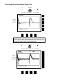
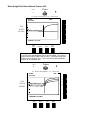
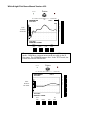
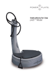
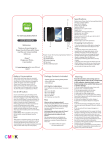
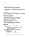
THE WHITE KNIGHT MANUAL
SECONDARY POWER LINE TAP LOCATOR
FIELD USER'S MANUAL
REVISION 1.1
FOR USE WITH SOFTWARE VERSION 4.20
NORTH AMERICAN MODEL
Arnett Industries, L.L.C.
20460 SW Avery Ct.
Tualatin, OR 97062
503-92-4600
IMPORTANT SAFETY INSTRUCTIONS
Please read all of these instructions before operating The White Knight:
Always wear rubber gloves and safety glasses when connecting the White Knight to energized power lines.
Never plug the White Knight into a meter socket that has voltages higher than 120V AC from the energized
terminals to neutral.
Make sure that the White Knight baseplate terminals do not pinch the White Knight neutral lead when inserted
into the meter socket!
Never lengthen or alter the White Knight Neutral lead: this can result in inaccurate test information.
The White Knight is a water-resistant, not watertight instrument, therefore, avoid using the unit in rainy
conditions. Water may penetrate through the front or rear panel openings, possibly damaging the instrument.
Avoid leaving the White Knight display in direct sunlight. Exposure to ultraviolet light can damage the display.
Avoid placing the White Knight on unstable platforms where it might fall and damage the unit.
Do not attempt to service the White Knight. Return the unit to Arnett Industries, L.L.C. for authorized service.
White Knight Field Users Manual Version 4.20
What is TDR?
The White Knight operates on Time Domain Reflectometry (TDR). Lines are checked for a period of time
(Time/Domain). The results are returned (Reflectometry) to the unit and displayed on the display.
The White Knight is calibrated to detect any change in impedance in the lines being tested. The line being tested
by the White Knight does not have to be energized to conduct the test.
The White Knight determines if taps exist based on assumptions characteristic of most taps. These assumptions
may not be true in all cases, which could result in the White Knight displaying inaccurate text mode information.
Arnett Industries, L. L. C. strongly suggests that the utility use other means, such as check meters, to support the
findings of the White Knight before digging up underground services or knocking out walls.
GENERAL OPERATION INSTRUCTIONS
CONDUCTING THE FIELD TEST:
Step 1
At least one day prior to its field use the White Knight's battery voltage should be checked to ensure it will
remain operational throughout the field test. The date and time should be verified for accuracy.
To check the battery voltage, press the POWER/UTILITY button on the face of the White Knight. The red
power light goes on and as the unit goes through some internal diagnostic self-checks, the battery voltage
appears on the screen along with the serial number, and the software version number. If the voltage goes below
8.0 volts, the White Knight needs to be recharged for at least eight hours.
To recharge the White Knight, utilize only the 12V DC Charger that accompanied the unit. Plug the charger into
any 120 V AC wall outlet and the 12V DC jack into the White Knight port marked 12V DC on the face of the
unit. Let the unit charge overnight. (Optional Accessory: Auto power Adapter: allows the White Knight to be
recharged from a 12-volt battery through an automobile cigarette lighter receptacle.)
Setting the time and date on the White Knight:
If the White Knight is not displaying the correct date and time, insert the calibration key (located on the strap of
the unit) into the printer port on the face of the White Knight. Press the POWER/UTILITY button on the face of
the unit and wait for the Main Menu to be displayed. Press the SET TIME button and utilize the UP/DOWN
arrows to set the date and time. Press the SET TIME button again. The White Knight displays the information
just entered. The Main Menu is now displayed and you can either proceed to another function or Turn Off the
unit by pressing and holding the POWER/UTILlTY button while the screen counts down from 4 to Power Off.
Release the POWER/UTILITY button and remove the calibration key from the printer port.
Step 2
Safety First!! Be sure to wear the required safety equipment as determined by your company.
Disconnect the energized service wire(s) from meter or disconnect switch leading to transformer.
When using meter base adapter for three wire services: Connect the green ground clip to the service neutral and
attach the black and red clips to the energized service conductors.
When using the meter base adapter for two wire services: Connect the black clip to the service neutral and the
red clip to the energized service conductor.
For use on single-phase socket type meter bases: Connect the green ground clip to the service neutral and insert
the plug into one of the White Knight ground (neutral) receptacles. Insert the White Knight into the meter socket
the same as installing a meter.
Step 3
Press and release the POWER/UTILITY button on the face of the White Knight. As described in Step 1, the unit
will conduct internal self-checks and will display a message indicating that this self test is taking place and to
Please Wait. It takes about 12 seconds for the test to complete and display the Main Menu. The Main Menu
displays the battery voltage in the upper left corner and the date, time, unit serial number and the software
version in the lower left comer. The right side of the Main Menu screen displays the following White Knight
functions adjacent to their respective buttons: NO SAVED DATA; OVERHEAD; UNDERGROUND; OTHER;
CAL DATES. The Overhead, Underground and Other options are used to acquire data, the Cal Dates shows the
date the White Knight was calibrated (See Calibration section for details on performing this function)
White Knight Field Users Manual Version 4.20
Step 4
In order to begin an investigation, choose the appropriate type of service to be tested, i.e. UNDERGROUND or
OVERHEAD.
BATTERY 8.24 V
NO SAVED DATA
OVERHEAD
UNDERGROUND
OCT 15, 1998
2:33:51 PM
Serial WK0140
SW V4.13
OTHER
CAL DATES
Step 5
The next screen lists three (3) of the most common cable sizes, which have been calibrated into the White
Knight's memory. Select the one that matches the size of the cable to be tested. It is useful to know the cable size
in advance so you can calibrate the White Knight to the other size cable prior to the field test. (See the
Calibration section for details on performing this function.)
OVERHEAD CABLE SELECT
#2-#2-#4
L:0.29in N:0.23in D
1/0-1/0-#2
L:0.37in N:0.29in D
SE4/0-SE4/0-#2/0
L:0.52in N:0.41in D
CANCEL
Step 6
The next selection you must make is whether the ground conditions are DAMP or DRY. To test an underground
service you must make DAMP or DRY selection. Overhead, on the other hand, is always tested as dry. A heavy
rain may cause the topsoil to be damp, however the ground may be dry at the depth of the unauthorized tap. If
you are uncertain, conduct the test utilizing the damp setting and test again utilizing the dry setting.
Step 7
The White Knight now displays the Tap Rejection Screen. Transformers and junction boxes are considered
'legitimate' taps. The White Knight detects all taps -- legal and illegal -- within 500 feet of the meter. 'Legitimate'
taps can be avoided by estimating the distance to the 'legitimate' tap and rejecting those taps. The White Knight
ignores all transformers or legitimate taps beyond your selected distance from the meter installation. You also
have the option of selecting the CANCEL button and conduct the test without any Tap Rejection.
To set the correct distance change the distance by pushing the UP or DOWN buttons to the closest estimated
distance.
Once the OK or CANCEL button is pressed, the White Knight begins the ACQUIRING DATA mode.
White Knight Field Users Manual Version 4.20
The White Knight acquires data in 12 seconds.
OVERHEAD CABLE SELECT
0_DRY #2-#2-#4
0_DAMP #2-#2-#4
CANCEL
TAP REJECTION
ENTER DISTANCE
TO LEGITIMATE
TAP OR
TRANSFORMER
POWERING CABLE
UNDER TEST
UP
DOWN
120 ft
TO TEST
WITHOUT TAP
REJECTION
PRESS CANCEL
OK
CANCEL
If uncertain on the DAMP or DRY condition of the underground service, conduct two tests; utilizing both the
DAMP setting and the DRY setting.
Step 8
The data acquired displays on the screen at the conclusion of the test, which takes approximately 12 seconds.
The information displays in one of three screen modes:
TEXT STEP
PULSE
Note: The top of the screen displays the type of service, condition and cable size. The bottom of the screen
shows date and time of the test.
Each screen displays the same data acquired from the test in different modes. Use of the screen 'mode' depends
on the user's preference on tap analysis. The 'mode' screen will return to the last screen displayed the next time
the White Knight is turned on and data is acquired or a saved investigation is recalled.
Step 9
At this point, the data should be saved for future analysis. Press the SAVE/RECALL button and choose a
location to save the data. The SAVE screen lists the type of service, condition, cable size, date and time.
Utilizing the appropriate arrows, type in an Identification Message by pressing the lower vertical button when
desired character blinks. Once the message is completed, save the data by pressing the SAVE/RECALL button.
(This message information may be bypassed for editing at a later time by pressing the SAVE/RECALL button).
ABCCB
SAVE IN LOCATION 1
RECALL LOCATION 1
CLEAR LOCATION 1
NEXT LOCATION
EDIT MESSAGE 1
White Knight Field Users Manual Version 4.20
Å
JAN 15, 1999
10:03:29 AM
O_DAMP #2-#2-#4
ABCDEFGH
IJKLMINP
QRSTUVWX
YZ123456
7890.,<>
LOAD IN MESSAGE
SAVE/RECALL when done
Step 10
Press and hold the POWER/UTILITY button. The screen will count down from 4 to Power Off the unit. Remove
the White Knight from the meter socket, reinstall the kWh meter and vacate the customer's premises.
RECALLING YOUR DATA
Recalling the results of stored field test data is as easy as acquiring the original data.
Press the POWER/UTILITY button. The White Knight completes it's self-test and displays the Main Menu
screen.
Press the RECALL button located along the right side of the White Knight faceplate. Look at the RECALL
LOCATION for the location to be reviewed. If the location number is not the location to be selected, press the
NEXT LOCATION button until the correct location is displayed. Press the RECALL LOCATION button to
bring up the saved data. (The White Knight can save up to eight investigations. To see the saved investigation
locations, press the SAVE/RECALL button along the bottom of the White Knight faceplate). After selecting the
RECALL LOCATION the White Knight will display the results of the field investigation in the screen mode
that was last displayed when the unit was turned off.
CHANGING THE SCREEN DATA VIEW
To view the results in a different mode or screen, press the DISPLAY button along the bottom of the White
Knight faceplate. Various options are shown. The STEP and PULSE modes will show the results in graph form
and the TEXT mode will display the data in words.
<STEP>
<L1-L2>
200
DISPLAY MODE
PULSE
TEXT
LINE SELECTION
L1-N
L2-N
RANGE IN FEET
100
<50>
25
SEPARATION
<YES>
NO
SENSITIVITY
<NORMAL>
HIGH
White Knight Field Users Manual Version 4.20
The LINE SELECTION will show L1-L2, L1-N, L2-N or ALL. L1 and L2 are the energized legs for a three
wire service and N is the neutral.
The RANGE IN FEET selections allow looking at the investigation data in graphical form from 25 to 500 feet
from the White Knight baseplate. It is best to begin the review of the graphical data in the 100 feet range. If the
White Knight data has determined that a tap is located 150 feet from the meter, the RANGE IN FEET should be
set at 200 feet. If a tap is detected 35 feet from the meter, the RANGE IN FEET should be set at 50 feet. This
option gives the operator different views of the same graph.
If you choose NO for the SEPARATION, the L1-L2, L1-N, L2-N graphs will superimpose one another. By
choosing YES, the L1-L2, L1-N, L2-N graphs will display each line apart from one another making it much
easier to follow the lines charted.
The SENSITIVITY NORMAL/HIGH selection gives the option of increasing the graph fluctuations. The HIGH
setting increase the amplitude of the graph fluctuations. Peaks and valleys in the graph become higher and lower
respectively, making it easier to see changes in impedance. This makes fine graphical analysis easier.
VIEWING THE DATA:
From the DISPLAY mode screen, make the selections that correspond to the user's ease of reviewing the
investigation data and press the DISPLAY button.
In the STEP mode, the dotted horizontal line is the TAP ALERT line. When the graph line dips below the TAP
ALERT line, it is likely that a tap exists. The long rectangular box on the graph confirms the existence of a tap
and its location. Move the cursor, using the left arrow button, to the center of the rectangular box for the location
of the tap. The distance, in feet, will display at the bottom of the screen. At this point you can print the data and
turn the unit off. Be sure to save your investigation data before turning the White Knight off. (OPTIONAL
ACCESSORY: Portable printer can be used to print any of the data from the White Knight.)
Arnett Industries, L.L.C. has determined that the most accurate data is obtained utilizing the STEP mode and the
results of L1-L2.
NOTE: Recalling and viewing the data functions can be done in the field as well as in your office. However this
should not be done while at the meter location.
USER SELECTABLE ENGLISH OR METRIC MODE:
Version 4.13 adds a control for displaying distances in feet or meters and cable diameters in inches or
millimeters. To set the control, insert the calibration key and turn ON the unit. Press SET TIME and in the next
display press NEXT ITEM until ENGLISH or METRIC blinks. Press one of the arrow keys to change to the
desired units, then press SET TIME to save the change. Power OFF the unit and remove the calibration key.
CALIBRATING THE WHITE KNIGHT
The White Knight comes with the most commonly used cable sizes stored in its memory. The White Knight can
also be calibrated to other cable sizes by following these steps:
Step 1
You will need a minimum of three (3) lengths of 50 feet of untapped cable, in the size that you want to calibrate.
At least fifty feet of cable is needed to establish normal impedance.
Step 2
Connect one (1) length of the 50-foot cable to the green neutral wire of the White Knight. Utilizing terminal
blocks that have been removed from a meter socket, connect the other two (2) 50 foot lengths of cable to the two
(2) top terminals. Then plug the White Knight into this terminal block making certain that the top blades on the
backside of the unit are inserted into the terminals that house the cables. (OPT1ONAL ACCESSORY: A
Portable Meter Base Adapter can also be used to calibrate the White Knight to various size cables.)
Step 3
Insert the calibration key that comes attached to the White Knight strap into the printer port on the face of the
unit and press the POWER/UTILITY button.
Press and hold CAL button and then press the OTHER button. Next press and hold CAL button and press the
TEST CABLE button.
The next screen explains that you are about to test a 50foot length of cable. Press the OK button to proceed. The
next screen also requires that you press OK to continue and then finally press YES to begin acquiring data.
White Knight Field Users Manual Version 4.20
Step 4
For this step, the exact length of the cable to be calibrated needs to be known. For example, we will say the
cable length is 56 feet. When the White Knight has completed acquiring the data, a graph displays on the
screen. The solid vertical cursor will be positioned at about the middle of the graph and the distance at the
bottom of the screen will read 49 feet. The cursor line should be moved to where the cable either rises (if the
cable end is open) or drops (where the cable terminates at the transformer). To change the cursor distance to the
correct distance, press and hold the bottom vertical button while pressing the arrow cursor button UP or DOWN
until the distance in feet on the bottom of the screen says 56 feet.
Step 5
Now move the cursor left approximately 5 feet from its current location. To do this, press the left arrow button 5
times. Press the select button. The solid line is now located at the far left of the screen and a dotted line is
displayed.
Step 6
Utilizing the right arrow button, relocate the solid vertical line (now located at the far left of the screen) to at
least 10 feet from the dotted line. As you adjust the distances, the measurement displays at the bottom of the
screen. Your objective is to have the distance between the dotted line and the solid line as flat as possible on the
graph.
Step 7
Press SAVE/RECALL. The White Knight is now calibrated to the size cable you utilized. Press
SAVE/RECALL again to select a location to store your data. You can now utilize the appropriate ARROW
buttons to identify the cable calibrated. Press SAVE/RECALL again, and press YES.
Step 8
Turn off the unit and remove the calibration key from the Printer port.
EXPANDED CAL DATES DISPLAY
When the need to review when the White Knight was last calibrated, press the MORE button until the cable
number to be view is displayed. The calibration is shown on the display. Calibration dates can be printed by
pressing the 'PRINT' button while viewing the CAL DATES display.
H.J. Arnett Industries, L.L.C.
The following examples are the White Knight's display of graphs from field investigations. By
becoming familiar with the basic waveforms, you will be able to determine if taps exist.
Printer
Con trast
H.J. ARNETT INDUSTRIES, L. L.C. - PORTLAND,
OR
28 FR OM METER
Te st c abl e
TH E
W HIT E
KN IGHT
.
.
.
.
.
.
.
.
.
.
.
.
.
.
.
.
.
.
.
.
.
.
.
.
.
.
.
.
.
.
.
.
.
.
.
LOC1
.
.
.
.
.
.
.
.
.
.
.
.
.
.
.
.
.
.
.
.
.
.
.
.
.
.
.
.
.
.
.
.
.
.
.
.
.
.
.
.
.
.
.
.
.
.
.
.
.
C
U
R
S
O
R
S
Selec
White Knight Field Users Manual Version 4.20
Printer
Con trast
H.J. ARNETT INDUSTRIES, L. L.C. - PORTLAND,
OR
28 FROM METER
LIVE
Test cable
TH E
W HIT E
KN IGHT
.
.
.
.
.
.
.
.
.
.
.
.
.
.
.
.
.
.
.
.
.
.
.
.
.
.
.
.
.
.
.
.
.
.
.
.
.
.
.
.
.
.
.
.
.
.
.
.
.
.
.
.
.
.
.
.
.
.
.
.
.
.
.
.
.
.
.
.
.
.
.
.
.
.
.
.
.
.
.
.
.
.
.
.
C
U
R
S
O
R
S
CURSOR = 28 FEET
Power /
Utility
Display
Save /
Reca ll
Print
ABOVE: Pulse mode, 100-foot range Test Cable, Tap graph
superimposed with same line untapped. Tap at 28 feet.
BELOW: Step mode, 100-foot range Test Cable, Tap graph
superimposed with same line untapped. Tap at 28 feet.
Printer
Con trast
H.J. ARNETT INDUSTRIES, L. L.C. - PORTLAND,
OR
28 FROM METER
LIVE
Test cable
TH E
W HIT E
KN IGHT
.
.
.
.
.
.
.
.
.
.
.
.
.
.
.
.
.
.
.
.
.
.
.
.
.
.
.
.
.
.
.
.
.
.
.
.
.
.
.
.
.
.
.
.
.
.
.
.
.
.
.
.
.
.
.
.
.
.
.
.
.
.
.
.
.
.
.
.
.
.
CURSOR = 28 FEET
Power /
Utility
Display
Print
Save /
Reca ll
.
.
.
.
.
.
.
.
.
.
.
.
.
.
C
U
R
S
O
R
S
White Knight Field Users Manual Version 4.20
Printer
Con trast
H.J. ARNETT INDUSTRIES, L. L.C. - PORTLAND,
OR
CLEAR
Test cable
.
.
.
.
.
.
.
TH E
W HIT E
KN IGHT
.
.
.
.
.
.
.
.
.
.
.
.
.
.
LIVE
.
.
.
.
.
.
.
.
.
.
.
.
.
.
.
.
.
.
.
.
.
.
.
.
.
.
.
.
.
.
.
.
.
.
.
.
.
.
.
.
.
.
.
.
.
.
.
.
.
.
.
.
.
.
.
.
.
.
.
.
.
.
.
C
U
R
S
O
R
S
CURSOR = 49 FEET
Power /
Utility
Display
Save /
Reca ll
Print
Both graphs on this page are the same investigation. Pulse
mode, 100 feet range, on untapped line of 50 feet length. Top
shows single line, bottom shows all three lines. These are the
normal impedance graphs on an untapped line.
Printer
Con trast
H.J. ARNETT INDUSTRIES, L. L.C. - PORTLAND,
OR
CLEAR
Test cable
TH E
W HIT E
KN IGHT
.
.
.
.
.
.
.
.
.
.
.
.
.
.
.
.
.
.
.
.
.
LIVE
.
.
.
.
.
.
.
.
.
.
.
.
.
.
.
.
.
.
.
.
.
.
.
.
.
.
.
.
.
.
.
.
.
.
.
.
.
.
.
.
.
.
.
.
.
.
.
.
.
CURSOR = 49 FEET
Power /
Utility
Display
Print
Save /
Reca ll
.
.
.
.
.
.
.
.
.
.
.
.
.
.
C
U
R
S
O
R
S
White Knight Field Users Manual Version 4.20
Printer
Con trast
H.J. ARNETT INDUSTRIES, L. L.C. - PORTLAND,
OR
CLEAR
Test cable
TH E
W HIT E
KN IGHT
.
.
.
.
.
.
.
.
.
.
.
.
.
.
.
.
.
.
.
.
.
LIVE
.
.
.
.
.
.
.
.
.
.
.
.
.
.
.
.
.
.
.
.
.
.
.
.
.
.
.
.
.
.
.
.
.
.
.
.
.
.
.
.
.
.
.
.
.
.
.
.
.
.
.
.
.
.
.
.
.
.
.
.
.
.
.
C
U
R
S
O
R
S
CURSOR = 49 FEET
Power /
Utility
Display
Save /
Reca ll
Print
Both graphs on this page are the same investigation. STEP mode,
100 feet range, on untapped line of 50 feet length. Up swing of
graph shows OPEN cable (end of cable). Top shows single line,
bottom shows all three lines. These are the normal impedance
graphs on an untapped line.
Printer
Con trast
H.J. ARNETT INDUSTRIES, L. L.C. - PORTLAND,
OR
CLEAR
LIVE
Test cable
TH E
W HIT E
KN IGHT
.
.
.
.
.
.
.
.
.
.
.
.
.
.
.
.
.
.
.
.
.
.
.
.
.
.
.
.
.
.
.
.
.
.
.
.
.
.
.
.
.
.
.
.
.
.
.
.
.
.
.
.
.
.
.
.
.
.
.
.
.
.
.
.
.
.
.
.
.
.
CURSORS = 49 FEET
Power /
Utility
Display
Print
Save /
Reca ll
.
.
.
.
.
.
.
.
.
.
.
.
.
.
C
U
R
S
O
R
S
White Knight Field Users Manual Version 4.20
Printer
Con trast
H.J. ARNETT INDUSTRIES, L. L.C. - PORTLAND,
OR
NEAR METER
LOC 2
Test cable
TH E
W HIT E
KN IGHT
.
.
.
.
.
.
.
.
.
.
.
.
.
.
.
.
.
.
.
.
.
.
.
.
.
.
.
.
.
.
.
.
.
.
.
.
.
.
.
.
.
.
.
.
.
.
.
.
.
.
.
.
.
.
.
.
.
.
.
.
.
.
.
.
.
.
.
.
.
.
.
.
.
.
.
.
.
.
.
.
.
.
.
.
C
U
R
S
O
R
S
Test cable
CURSORS = 2 FEET
Power /
Utility
Display
Save /
Reca ll
Print
These two graphs show the same investigation in different
modes. Both show a tap near meter on the test cable in the 50
feet range. The CURSOR is at two feet. In the TEXT mode, the
screen will read NEAR METER.
Printer
Con trast
H.J. ARNETT INDUSTRIES, L. L.C. - PORTLAND,
OR
TH E
W HIT E
KN IGHT
.
.
.
.
.
.
.
NEAR METER
Test cable
.
.
.
.
.
.
.
.
.
.
.
.
.
.
.
.
.
.
.
.
.
.
.
.
.
.
.
.
LOC 2
.
.
.
.
.
.
.
.
.
.
.
.
.
.
.
.
.
.
.
.
.
.
.
.
.
.
.
.
.
.
.
.
.
.
.
Test cable
CURSOR = 2 FEET
Power /
Utility
Display
Print
Save /
Reca ll
.
.
.
.
.
.
.
.
.
.
.
.
.
.
C
U
R
S
O
R
S
White Knight Field Users Manual Version 4.20
Printer
Con trast
H.J. ARNETT INDUSTRIES, L. L.C. - PORTLAND,
OR
LOC1
28 FROM METER
Test cable
TH E
W HIT E
KN IGHT
.
.
.
.
.
.
.
.
.
.
.
.
.
.
.
.
.
.
.
.
.
.
.
.
.
.
.
.
.
.
.
.
.
.
.
.
.
.
.
.
.
.
.
.
.
.
.
.
.
.
.
.
.
.
.
.
.
.
.
.
.
.
.
.
.
.
.
.
.
.
.
.
.
.
.
.
.
.
.
.
.
.
.
.
C
U
R
S
O
R
S
Test cable
CURSOR = 28 FEET
Power /
Utility
Display
Save /
Reca ll
Print
These two graphs show the same investigation in different modes. Both
show a tap at 28 feet on the test cable in the 100 feet range. The
CURSOR is at 28 feet. In the TEXT mode, the screen will read TAP
28 FEET FROM METER.
Printer
Con trast
H.J. ARNETT INDUSTRIES, L. L.C. - PORTLAND,
OR
TH E
W HIT E
KN IGHT
.
.
.
.
.
.
.
28 FROM METER
Test cable
.
.
.
.
.
.
.
.
.
.
.
.
.
.
.
.
.
.
.
.
.
.
.
.
.
.
.
.
LOC1
.
.
.
.
.
.
.
.
.
.
.
.
.
.
.
.
.
.
.
.
.
.
.
.
.
.
.
.
.
.
.
.
.
.
.
Test cable
CURSOR = 28 FEET
Power /
Utility
Display
Print
Save /
Reca ll
.
.
.
.
.
.
.
.
.
.
.
.
.
.
C
U
R
S
O
R
S