1
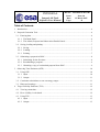
INTEGRAL
Science Operations Centre
Software User Manual
AO-5 Observation Tools Software User Manual
INT/SDG/07-0277/Dc
Issue 1.0
12 March 2007
Prepared by P. Balm and G. Bélanger
Authorised by P. Kretschmar
Doc.No: INT/SDG/07-0277/Dc
INTEGRAL
Integral AO Tools
Software User Manual
Issue:
Date:
Page:
Issue 1.0
12 March 2007
ii
Document Status Sheet
Document Title
AO-5 Observation Tools Software User Manual
Reference No:
INT/SDG/07-0277/Dc
Issue
Revision
Date
Reason for change
1
1
12 March 2007
Issue for AO-5
INTEGRAL
Integral AO Tools
Software User Manual
Doc.No: INT/SDG/07-0277/Dc
Issue:
Date:
Page:
Issue 1.0
12 March 2007
iii
Table of Contents
1
Introduction.................................................................................................................................... 4
2
Proposal Generation Tool .............................................................................................................. 4
2.1
Entering data............................................................................................................................ 4
2.1.1 The Main Panel ................................................................................................................. 4
2.1.2 The Admin, Proposal and Observation Details Panels ..................................................... 5
2.2
Saving, loading and printing.................................................................................................... 7
2.2.1 Saving................................................................................................................................ 7
2.2.2 Loading.............................................................................................................................. 7
2.2.3
2.3
Printing .............................................................................................................................. 7
Submitting a proposal to ISOC................................................................................................ 8
2.3.1 Submitting for the first time .............................................................................................. 8
2.3.2 Resubmitting a proposal.................................................................................................... 9
2.3.3 Obtaining a copy of a submitted proposal from ISOC...................................................... 9
3
Observing Time Estimator (OTE) ............................................................................................... 10
3.1
Using OTE............................................................................................................................. 10
3.1.1 Input ................................................................................................................................ 10
3.1.2 Output.............................................................................................................................. 11
4
3.2
Continuum calculations: a note on energy ranges ................................................................. 11
3.3
Hints and warnings ................................................................................................................ 11
Target Visibility Predictor (TVP) ................................................................................................ 12
4.1
Viewing constraints ............................................................................................................... 12
4.2
How visibility is calculated ................................................................................................... 12
4.3
Using TVP ............................................................................................................................. 13
4.3.1 Input ................................................................................................................................ 13
4.3.2 Output.............................................................................................................................. 13
INTEGRAL
Doc.No: INT/SDG/07-0277/Dc
Integral AO Tools Software
User Manual
Issue:
Date:
Page:
Issue 1.0
112 March 2007
4 of 13
1 Introduction
The purpose of this document is to describe the use of the software tools made available to
observers who wish to submit a proposal for INTEGRAL observations.
The Integral AO Tools provided by the INTEGRAL Science Operations Centre (ISOC) include: the
Proposal Generation Tool (PGT), the Observation Time Estimator (OTE) and the Target Visibility
Predictor (TVP). The latest version of these tools together with the associated documentation are
available from the ISOC web page: http://integral.esac.esa.int.
If you discover a problem with any of the tools, please read the Frequently Asked Questions (FAQ)
at http://integral.esac.esa.int/FAQ. If you do not find the answer to your question, please contact the
INTEGRAL Helpdesk: mailto:[email protected].
2 Proposal Generation Tool
PGT can be downloaded from: http://integral.esac.esa.int/isoc/operations/html/pgtao5. Installation
instructions and answers to FAQ are also provided there.
Once PGT has been successfully installed, it is launched by running an executable script called
“pgt” on UNIX-like platforms, or by double-clicking on the desktop icon on Windows systems.
2.1 Entering data
2.1.1 The Main Panel
When the PGT is launched, the Main Panel is displayed (Figure 1). This panel serves as the parent
to the Admin Details Panel, the Proposal Details Panel and the Observation Details Panel, all of
which can be accessed by clicking the appropriate button found in the top half of the Main Panel.
Figure 1 - The Main Panel of PGT
INTEGRAL
Integral AO Tools Software
User Manual
Doc.No: INT/SDG/07-0277/Dc
Issue:
Date:
Page:
Issue 1.0
112 March 2007
5 of 13
Below these three buttons, there is a Check Proposal button that initiates a series of checks on the
proposal and lists anything that is wrong or incomplete. This check can be performed at any time.
The lower half of the Main Panel is controls proposal submission (or resubmission). Clicking the
Submit Proposal to ISOC button, will send an electronic version of the proposal to the ISOC.
2.1.2 The Admin, Proposal and Observation Details Panels
PGT provides three details panels that encompass all the information about the proposal. These
include: administrative details, proposal details and observation details, and are accessed by
clicking the corresponding button in the Main Panel. All fields, in any panel, that have a light
yellow background are mandatory and cannot be left blank.
2.1.2.1 Admin Details Panel
This panel serves to enter contact information for the principal investigator.
2.1.2.2 Proposal Details Panel
This panel serves to enter the title and abstract of the proposal, its scientific category and to attach
the scientific justification. Selecting to associate the proposal with a Key Programme is done here.
Association of a proposal with a Key Programme
At the bottom of the panel, there is a checkbox labelled Associate with Key Programme. Selecting
this option will associate the proposal with a Key Programme (KP). Such a proposal is referred to as
a KP subscription by ISOC. See document “AO-5 Key Programmes and Associated Observations”
(INT/SDG/07-0270/Dc) for details on the planned Key Programmes.
Scientific Justification
At the bottom of the Proposal Details Panel, the button labelled New Attachment (see Figure 2) is
used to attach the proposal’s scientific justification in PostScript or PDF format.
Figure 2 – Attaching the scientific justification
INTEGRAL
Integral AO Tools Software
User Manual
Doc.No: INT/SDG/07-0277/Dc
Issue:
Date:
Page:
Issue 1.0
112 March 2007
6 of 13
Having selected the attachement, the name of the file will be shown in the Current Attachment
box of the Proposal Details Panel. Saving the proposal also saves the attachment (in compressed
form). Hence, there is no need to re-attach the file every time the proposal is loaded. Clearly, if you
make changes to the scientific justification after the file has been attached to the proposal, you must
override the previous attachment by attaching the new version.
There is no need to ever remove an attachment; only the last attachement is used. Selecting Panel
→ Reset will clear all field and remove the attachment.
2.1.2.3 Observation Details Panel
This panel serves to enter the technical details of each observation included in the proposal.
Each observation is numbered and identified in the Number field in the top left corner of the panel,
in the tool bar. There, one can simultaneously see the number of the currently displayed observation
and the total number of observations. Observations are numbered sequencially according to the
order in which they were added. If one of several observations is removed, all subsequent
observations will be re-numbered accordingly.
Figure 3 - The Observation Details Panel (upper part)
The Observation Details Panel has an additional menu item labelled Observation (see Figure 4)
used to Add, Delete, Duplicate and Check the observation, or to Go To another observation.
Figure 4 - The Observation Menu
INTEGRAL
Doc.No: INT/SDG/07-0277/Dc
Integral AO Tools Software
User Manual
Issue:
Date:
Page:
Issue 1.0
112 March 2007
7 of 13
If the proposal is associated with a KP, only the target source information has to be provided: all
instrument settings are defined in the KP. For this reason, some fields in the Observation Details
Panel are disabled for KP subscriptions.
2.2 Saving, loading and printing
2.2.1 Saving
To save a proposal at any time, select File → Save in the menu of the Main Panel (see Figure 1).
2.2.2 Loading
To load a saved proposal, select File → Open in the menu of the Main Panel.
2.2.3 Printing
To print a proposal or parts of it, first choose the printing options by selecting File → Print →
Options in the menu of the Main Panel. This will open the Print Options dialog box (see Figure 6).
Figure 5 - The Print Options dialogue
Two paper sizes are supported, A4 and US letter. Click on the appropriate button at the top of the
dialogue to choose the paper size. The list of fonts from which you can select will appear below.
After having selected the paper size and font, set them by clicking OK or Cancel to disregard de
selection and close the dialogue.
To print the entire proposal, select File → Print → Proposal in the menu of the Main Panel. A
Print dialogue will appear and allow you to select a destination (printer or file) and start the print
job. The exact appearance of this dialogue will depend on the platform you are using.
The administrative details and the proposal details can be printed individually by selecting Panel →
Print in the menu bar of the corresponding panel.
INTEGRAL
Integral AO Tools Software
User Manual
Doc.No: INT/SDG/07-0277/Dc
Issue:
Date:
Page:
Issue 1.0
112 March 2007
8 of 13
Observation details can be printed by selecting Panel → Print → All Observations to print all the
obervations, or by selecting Panel → Print → Current Observation to print an individual
observation. To print a summary of all the observations in the proposal (one observation per line),
select Panel → Print → Summary.
2.3 Submitting a proposal to ISOC
The PGT allows you to send your proposal electronically to the ISOC. To do this, your computer
must be connected to the Internet.
2.3.1 Submitting for the first time
Clicking the Submit Proposal to ISOC button in the lower part of the Main Panel (see Figure 1)
starts the submission process. PGT will first check your proposal. If it fails any checks, the
submission process will be aborted and you will need to correct the errors shown in the Failed
Checks Panel. If it passes the checks, a panel is displayed showing a summary of the proposal.
Click Submit to send the proposal, Cancel to abort the submission.
One of the checks is the verification of the source coordinates using the Simbad database. In case
the name of your source is not found or if the coordinates are different, a warning is printed in the
Failed Checks Panel; this will not prevent the submission of the proposal. If your PC is not
connected to the Internet, a warning to this effect is printed and the submission to ISOC can clearly
not be completed.
Figure 6 - The Summary Panel
By clicking Submit, PGT will attempt to establish a connection with a computer at ISOC that has
been set up to receive proposals. Once it is established, the proposal will be sent. If the proposal was
sent successfully, the following dialogue will be displayed.
Upon receipt of a proposal, the computer at the ISOC performs further checks and sends a receipt
confirmation email message. If the proposal passes the checks, a Proposal ID will be assigned to it
and included in the message. If it does not, this will be stated in the email.
INTEGRAL
Doc.No: INT/SDG/07-0277/Dc
Integral AO Tools Software
User Manual
Issue:
Date:
Page:
Issue 1.0
112 March 2007
9 of 13
Figure 7 - Successful Submission dialogue
2.3.2 Resubmitting a proposal
If you realise you have made a mistake, or simply want to make changes to a proposal you have
already submitted, you can resubmit a proposal using the Proposal ID.
Make the changes you wish to make to the proposal and enter the Proposal ID in the box provided
at the bottom of the Main Panel (see Figure 1). The Resubmit Proposal to ISOC button will be
enabled and the Submit Proposal to ISOC button will be disabled. When you click the Resubmit
Proposal to ISOC button, PGT will repeat the proposal submission process, described above.
The computer at ISOC will use the Proposal ID entered to find the previous version of the proposal
in the ISOC database. If it is found, the resubmitted proposal will replace the previous one. If it is
not found, the receipt confirmation email message will inform you of that fact (make sure the
Proposal ID is correct).
It is NOT permitted to change the status of the proposal from one that is associated with a KP to
one that is not or vice versa: the Associate to Key Programme checkbox on the Proposal Details
Panel must remain in its original state in the resubmission.
It is NOT permitted to change the KP with which the proposal is associated.
In either of these cases, simply submit the proposal as a new one, without specifying an ID. You
will then be given a new ID that is compatible with your selection.
PGT cannot prevent a proposer from submitting the same proposal multiple times as new proposals.
A new Proposal ID will be generated for each new submission. Therefore, be cautious when
resubmitting a modified version of the same proposal.
2.3.3 Obtaining a copy of a submitted proposal from ISOC
After submitting a proposal, it should be saved (see section 2.2) for future reference, and to allow
for the possibility of resubmitting the proposal at a later date.
You can also request a copy of your proposal by sending an email to the ISOC Helpdesk
(mailto:[email protected]) stating that you would like a copy of your proposal, referring to it
with the corresponding Proposal ID. It will be emailed to you at the address specified in the Admin
Details Panel of PGT. If another email address should be used, specify this in the message.
INTEGRAL
Integral AO Tools Software
User Manual
Doc.No: INT/SDG/07-0277/Dc
Issue:
Date:
Page:
Issue 1.0
112 March 2007
10 of 13
3 Observing Time Estimator (OTE)
The Observing Time Estimator (OTE) is a web-based tool running at the INTEGRAL Science
Operations Centre at ESAC and made available to potential observers. Below is a description of
OTE version 5. Improvements over the previous version includes a considerable increase in speed
and slight changes in presentation. However, the underlying response data is unaltered.
The purpose of the OTE is to give users a reliable guide as to the feasibility of their proposed
observation. For example, given specific source characteristics (spectrum, flux), OTE computes the
signal-to-noise ratio (S/N) achievable in a given observing time, or conversely, the integration time
needed to achieve a desired S/N.
OTE can currently be used only for INTEGRAL’s main instruments: SPI and IBIS. Not for JEM-X
and OMC (interested users should refer to the JEM-X and OMC Observer’s manual for details). All
INTEGRAL proposers should use OTE in determining the duration of their proposed observations.
These values are used by ISOC in the proposal’s technical feasibility assessment used by the TAC.
OTE is accessed via the ISOC web site, http://integral.esac.esa.int, by clicking on ‘Observation
Tools’ under ‘INTEGRAL Announcement of Opportunity (AO)’.
3.1 Using OTE
3.1.1 Input
•
Select an instrument: SPI or IBIS.
•
Select a continuum or line source.
•
- For a continuum calculation the user must set the lower and upper energies. The allowed
range is 15 keV–10 MeV. OTE assumes a power law spectrum and the photon spectral
index must be specified in the GUI. If you wish to perform calculations for a continuum
source, please make sure to read section 3.4.
- For a line source, input the central energy and line width (FWHM). If the line is
unresolved, a line width of 0.1 keV is sufficient.
Specify the S/N or the exposure time.
•
Specify the source flux.
- This is the broad-band flux, in units of photons cm-2s-1, in either the selected energy range
(for the continuum) or integrated over the full width at zero intensity (FWZI) for a line.
Beware! The continuum sensitivity curves in the SPI and IBIS Observer’s manuals are
presented using different units: monochromatic flux density, i.e., photons cm-2s-1keV-1.
- Enter the source position (optional) in either degrees or sexagesimal notation (J2000). OTE
accesses the 2nd ISGRI catalogue and warns the user if there are any nearby bright sources; a
bright source in the partially coded field of view can severely deteriorate image quality.
•
Select the desired dither pattern.
INTEGRAL
Doc.No: INT/SDG/07-0277/Dc
Integral AO Tools Software
User Manual
Issue:
Date:
Page:
Issue 1.0
112 March 2007
11 of 13
- This will take into account the off-axis response of the instruments as INTEGRAL dithers:
a very important effect for SPI but not for IBIS (staring is not recommended). We generally
recommend the 5x5 dither pattern (see the IBIS and SPI observer’s manuals).
•
Click the ‘Query’ button.
3.1.2 Output
OTE returns:
• The original input values
• Any nearby bright source information (coordinates from the 2nd ISGRI catalogue)
• Warnings, if part of the selected energy band for the source calculation is outside the energy
range of the selected instrument
• For continuum sources, the calculated exposure time, or S/N for the individual sub-bands
used in the back-end calculations. These may be useful, for example, for determining the
energy above which the source fades into the background
• Calculated exposure time, or S/N for the entire input energy range (for continuum sources)
or for the FWZI (line sources)
3.2 Continuum calculations: a note on energy ranges
While a broad energy range is allowed in the OTE input, the OTE back-end calculations themselves
do not allow the use of a broad energy band, e.g., 20 keV to 10 MeV. The underlying algorithm in
OTE calculates the average performance across a user defined continuum energy band given the
flux of the source in that band. However, the sensitivity of the instruments can vary enormously
over their energy ranges. In addition, the gamma-ray instruments can have very rapid changes in
sensitivity in a comparatively small range of energies (especially around 511 keV). Also, many
(most) gamma-ray sources exhibit steep spectra so that they are very much fainter at higher
energies. Even for hard sources, including the highest energies will result in very low S/N due to the
relatively high background at MeV energies, compared to the source flux.
For these reasons, in previous AOs, OTE was restricted to energy bands which are narrower than
the entire instrumental bandpass. Of course the prospective observer may be in a situation where the
continuum range of interest is rather wide. To allow this the front-end (GUI) of OTE allow the user
to specify a wider band. OTE splits the input energy range into narrower sub-bands and, assuming a
power law spectrum (with the flux and spectral index as user inputs), calculates the flux within each
sub-band. It then performs individual calculations on these sub-bands, of the S/N, or observation
duration, and finally combines these results into a global figure for the entire input energy band.
3.3 Hints and warnings
(i) Units: Please be careful with units!
•
Input and ouput time are in kiloseconds
INTEGRAL
Integral AO Tools Software
User Manual
•
Doc.No: INT/SDG/07-0277/Dc
Issue:
Date:
Page:
Issue 1.0
112 March 2007
12 of 13
All fluxes, both for lines and continua, should be given in units of photons cm-2s-1
(ii) Prospective IBIS users should also note the following:
•
The continuum range of interest can straddle the energy ranges of ISGRI and PICsIT and be
only partially inside the energy range of one or both. If only one calculation is done for the
entire range of interest, both sub-instruments might report a poorer response than is truly
available. If one does go beyond the energy range of a (sub) instrument, a warning is given.
•
In such a case, we recommend calculating the broad-band flux for the energy range of
interest covered by ISGRI and by PICsIT separately and combining the results later.
(iii) The contributions of Compton photons to the S/N or observing time are not considered.
4 Target Visibility Predictor (TVP)
The Target Visibility Predictor (TVP) is a web-based tool running at the INTEGRAL Science
Operations Centre at ESAC and made available to potential observers.
TVP is used to determine when a source is visible to INTEGRAL. This is especially useful in
determining whether INTEGRAL observations can be coordinated with other observatories, and if
phase-dependent observations of binary systems, for example, can be performed.
TVP is accessed via the ISOC web site, http://integral.esac.esa.int, by clicking on ‘Observations
tools’ under ‘INTEGRAL Announcement of Opportunity (AO)’.
4.1 Viewing constraints
INTEGRAL celestial viewing constraints are defined by power and thermal constraints (Sun), as
well as star-tracker blinding constraints (Sun, Earth, Moon). The constraints used in this tool are
that the spacecraft cannot point within 50o of the Sun, more than 130o away from the Sun, within
15o of the Earth’s limb, or within 10o of the Moon’s limb.
Since the Earth and Lunar orbits can be predicted very accurately, it is also possible to predict when
any part of the celestial sphere is visible to INTEGRAL.
4.2 How visibility is calculated
Sky visibility is calculated by dividing the sky into approximately rectangular cells of 10 x 10
degrees referred to as skybins. The visibility of each corner of a skybin is determined for every
revolution in the mission, whenever INTEGRAL is above the Van Allen belts. If all four corners are
simultaneously visible, that area of sky is deemed visible. The calculation is therefore (slightly)
conservative. The results are stored in a Data Base of Observable Bins (DBOB), which contains the
open and close times for every skybin during the mission, and the resulting available duration. This
“open interval” never crosses revolution boundaries since science operations are not performed in
the Van Allen belts around perigee.
INTEGRAL
Integral AO Tools Software
User Manual
Doc.No: INT/SDG/07-0277/Dc
Issue:
Date:
Page:
Issue 1.0
112 March 2007
13 of 13
4.3 Using TVP
4.3.1 Input
•
RA and Dec (J2000) In either of the formats shown on the web page.
•
Dither pattern
For hexagonal or 5x5 dither patterns, the TVP checks whether all
points in the dither pattern are visible, not just the centre.
•
Start and End date
For the period of interest. Defaults are start and end dates in the
DBOB, which cover the interval to beyond the end of the AO cycle. It is recommended to
cover only the period of interest. Input should be in the format shown on the web page.
•
Minimum Duration In seconds. TVP will only return visibility of bins open for longer
than this value. In the DBOB, bins can be open for as short as one second (if the bin is at the
edge of the Earth or Moon constraint). However, the scheduling system would never attempt
to use such a bin. We suggest 1800 seconds as a reasonable value.
•
Maximum Duration In seconds. The longest possible open duration for a skybin is
approximately 64 hours. This corresponds to the time during which INTEGRAL is
continuously above the Van Allen belts. Thus we suggest that the maximum duration never
be greater than 228000 sec, otherwise TVP would never find any skybins visible.
4.3.2 Output
The output of TVP is a summary of the input parameters, and a time-ordered list of when the source
(skybin) is visible. Each line in the list contains start and end times (UTC), and duration of visibility
(seconds). Gaps of eight hours between successive visibility periods are usually due to Van Allen
belt transit. Shorter gaps are due to Earth or Moon constraints and longer gaps to Sun/anti-Sun
constraints.