1
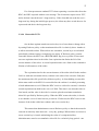
SECURING TEXT CHAT SYSTEM USING KERBEROS AUTHENTICATION
PRABU A/L JAGANADAN
UNIVERSITI TEKNOLOGI MALAYSIA
PSZ 19:16 (Pind. 1/97)
UNIVERSITI TEKNOLOGI MALAYSIA
BORANG PENGESAHAN STATUS TESIS
JUDUL :
.
SECURING TEXT CHAT SYSTEM USING KERBEROS AUTHENTICATION
SESI PENGAJIAN:
2004 /2005
-II
PRABU AIL JAGANADAN
(HURUF BESAR)
Saya
mengaku membenarkan tesis (pSMlSarjana/Doktor Falsafah)* ini disimpan di Perpustakaan Universiti
Teknologi Malaysia dengan syarat-syarat kegunaan seperti berikut:
1.
2.
Tesis adalah hakmilik Universiti Teknologi Malaysia.
Perpustakaan Universiti Teknologi Malaysia dibenarkan membuat salinan untuk tujuan pengajian
sahaja.
3. Perpustakaan dibenarkan membuat salinan tesis ini sebagai bahan pertukaran antara institusi
pengajian tinggi.
4. **Silatandakan( ..J )
D
D
o
SULIT
(Mengandungi maklumat yang berdarjah keselamatan
atau kepentingan Malaysia seperti yang termaktub di
dalam AKTA RAHSIA RASMI 1972)
TERHAD
(Mengandungi maklumat TERHAD yang telah ditentukan
oleh organisasi/badan di mana penyelidikan dijalankan.)
TIDAK TERHAD
Disahkan oleh
f)!JL
(TANDATANGAN PENULIS)
Alamat Tetap:
80 JALAN PESONA 11.
TAMAN PELANGI INDAH
81800 ULU TIRAM
JOHOR
Tarikh:
CATATAN:
29 MAR~H 2005
PM DR. MOHO AlZAINI BIN MAAROF
Nama Penyelia
Tarikh:
29 MARCH 2005
* Potong yang tidak berkenaan.
** Jika tesis ini SULIT atau TERHAD, sila lampirkan surat daripada pihak
berkuasa/organisasi berkenaan dengan menyatakan sekali sebab dan tempoh tesis
ini perlu dikelaskan sebagai SULIT atau TERHAD.
.
Tesis dimaksudkan sebagai tesis bagi Ijazah Doktor Falsafah dan Sarjana secara
penyelidikan, atau disertasi bagi pengajian secara kerja kursus dan penyelidikan,
atau Laporan Projek Sarjana Muda (PSM).
SECURING TEXT CHAT SYSTEM USING KERBEROS AUTHENTICATION
PRABU A/L JAGANADAN
This thesis is delivered as a requirement for a
Degree of Bachelor of Science(Computer Science)
FAKULTI SAINS KOMPUTER DAN SISTEM MAKLUMAT
UNIVERSITI TEKNOLOGI MALAYSIA
MARCH 2005
"I declare that 1have read the thesis and approve that this thesis has fulfilled the scope
and quality criteria for the degree of Bachelor of Science (Computer Science)"
Signature
Name of Supervisor:
Date
PROF. MADYA DR. MOHDAIZAINI BIN MAAROF
Timbalan Dakan (Akademik)
Fakulti Sains Komputer dan Sistem Maklumat
Universiti Teknologi Malaysia
81310 UTM, Skudal, Johor.
I
",,'
11
"I declare that this project entitled is the result of my own work except as cited in
reference. The report has not been accepted for any degree and is not concurrently
submitted in candidature of any degree."
9:!lI:
Signature
:
....
Name of Author. . ... ...PRABU
NL JAGANADAN
...
... ............................................
..
29 MARCH 2005
Date
... ...
...
iii
To those who have trusted my capabilities …
iv
ACKNOWLEDGEMENT
I would like to take this opportunity to thank my supervisor, PM Dr. Mohd
Aizaini bin Maarof for accepting me to be under his supervision. I would also like to
express my gratitude to him for sparing his precious time in giving me constructive
suggestions and advise regarding my project.
I am also very grateful to my friends who gave me moral support for supporting
me in finishing this project. I would also like to thank my parents for giving me both
moral and material support all the way.
I am also greatly indebted to my seniors and friends for spending extra hours
with me in finishing this project and being there for me whenever I needed their help.
Words alone cannot express the thanks I owe to all of them who is involved directly or
indirectly supporting me in the completion of this report. Last but not least, I would want
to thank God for blessing me and being with me through my toughest times.
v
ABSTRACT
Information technology has made it possible for us to communicate through text
messages in a Local Area Network (LAN). However, transmission of text messages
through the network has limitation where it can be easily accessed by third party. This
text messages sent over the networks are prone to security threads such as interruption,
interception, modification and fabrication. The objective of this project is to secure the
transmission of text messages from unwanted parties in a chat system and to overcome
the Public Key Cryptographic disadvantages. Public key encryption probably strikes you
as complex. In fact, it is. It requires many computers processing cycle to do public key
encryption and decryption -about 100 times as many as cycle as symmetric key
encryption required. Besides that, there is problem to exchange the public key among
two parties even public key is not secret. If a person wan to initiate a connection with
another party in the network he need to get the public key of the other party who he wish
to communicate with. So there is a problem to get the public key of the other party to
start the communication. The approach used to overcome these problems is by using
Kerberos Network Authentication to distribute the secret key securely among two
parties. To add more security and secrecy to this system, the text messages are also
encrypted using the AES algorithm. The parallel development methodology was used in
this project. The text messages can only be sent to only one computer at one time
through the network. By exchanging messages this way, this system ensures the
messages sent cannot be accessed by an unauthorized person because he only sees an
encrypted text file being transferred.
vi
ABSTRAK
Teknologi maklumat telah memudahkan komunikasi melalui mesej berbentuk
teks dalam rangkaian kawasan setempat. Walaubagaimanapun, pemindahan mesej
berbentuk teks yang dihantar melalui rangkaian adalah tidak selamat daripada
penyampukan, pemintasan dan pengubahsuaian. Objektif projek ini adalah untuk
memastikan mesej yang dihantar di dalam satu sistem komunikasi adalah selamat
daripada capaian pihak ketiga dan juga untuk mengatasi masalah sistem penyulitan
awam. Masalah sistem kekunci awam yang paling utama diatasi melalui projek ini
adalah masalah untuk berkongsi satu kekunci rahsia antara dua komputer atau pengguna
yang berkomunikasi. Untuk membolehkan seseorang mengimplementasikan sistem
penyulitan awam ini, beliau perlu mengetahui kekunci awam bagi pihak yang ingin
beliau berkomunikasi. Menjadi satu masalah untuk memperolehi kekunci awam ini
walaupun kekunci umum bukan merupakan suatu kekunci yang perlu dirahsiakan.
Pendekatan yang digunakan untuk mengatasi masalah ini adalah dengan menyulitkan
text yang dihantar dengan satu kekunci rahsia yang diagihkan antara pengguna sistem
melalui mekanisma Kerberos. Untuk menambah keselamatan sistem ini, kaedah
penyulitan AES juga digunakan. Metodologi yang digunakan adalah metodologi
pembangunan selari. Projek ini telah dilaksanakan supaya mesej berbentuk teks akan
disulitkan dan untuk menunjukkan yang kaedah menyembunyikan mesej berbentuk teks
adalah sangat berkesan. Mesej berbentuk teks ini hanya boleh dihantar ke satu komputer
pada satu masa melalui rangkaian. Melalui pendekatan ini, dapat memastikan mesej
yang dihantar adalah selamat daripada pencerobohan orang yang tidak diingini kerana
dia hanya akan melihat suatu mesej yang tersulit sedang dihantar.
xi
LIST OF TABLES
TABLE NUM.
TITLE
PAGE
2.1
Fields of a Ticket
24
2.2
Ticket Flags
25
2.3
Applications for Asymmetric-key Cryptosystem
33
xii
LIST OF FIGURES
FIGURE NUM.
TITLE
PAGE
2.1
Mutual authentication (Alice-Bob)
11
2.2
Key Distribution (in theory)
12
2.3
Key Distribution (in practice)
13
2.4
Mutual authentication (Client/server)
14
2.5
AS Exchange
20
2.6
TGS Exchange
21
2.7
CS Exchange
22
2.8
Analogy of a Symmetric-key Cryptosystems
29
2.9
Analogy of an Asymmetric-key Cryptosystems
31
2.10
How Asymmetric-key Encryption Works
32
3.1
Life cycle of the parallel development methodology
41
3.2
The prototyping methodology
42
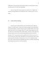
4.1
Overview of How the System Works
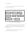
52
4.2
Process of sending messages
53
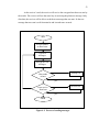
4.3
Process of receiving messages
54
4.4
Use Case for User
55
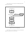
4.5
Use Case Diagram for User
56
4.6
Sequence diagram sending text message
57
4.7
Sequence diagram for encrypted text at receiver’s end
58
4.8
The Main User Interface for Chatting
59
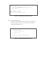
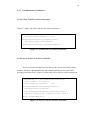
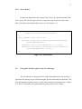
5.1
Command-line arguments by client
62
xiii
5.2
Command-line arguments by Server
62
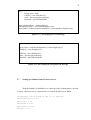
5.3
Client Code for Socket Connection
63
5.4
Server Code for Socket Connection
63
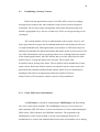
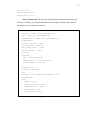
5.5
Client GSSContext Instantiation
65
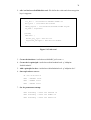
5.6
Client Context Establishment
66
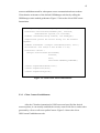
5.7
Server GSSContext Instantiation
67
5.8
Server Context Establishment
68
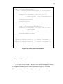
5.9
The Login Configuration File
69
5.10
Client. Policy
70
5.11
Server.policy
71
5.12
Encrypting the Text Message
72
5.13
Decrypting the encrypted text message
72
5.14
krb5.conf
73
5.15
kdc.conf
74
5.16
Encryption output
76
5.17
Decryption output
76
5.18
Message Validation
79
xiv
LIST OF ABBREVATION
KDC
-
Key Distribution Center
TGT
-
Ticket Granting Ticket
AES
-
Advanced Encryption Algorithm
DCT
-
Discrete Domain Transformation
DFD
-
Data Flow Diagram
DLL
-
Dynamic Link Libraries
ERD
-
Entity Relationship Diagram
FFT
-
Fast Fourier Transform
ICMP
-
Internet Message Control Protocol
JDK
-
Java Development Kit
JCE
-
Java Cryptography Extension
LAN
-
Local Area Network
LPC
-
Linear Predictive Coding
LSB
-
Least Significant Bit
MAN
-
Metropolitan Area Network
RAD
-
Rapid Application Development
SDAM
-
System Analysis and Design Method
SDLC
-
System Development Life Cycle
TCP
-
Transmission Control Protocol
UDP
-
User Datagram Protocol
UML
-
Unified Modeling Language
WAN
-
Wide Area Network
xv
LIST OF APPENDIX
APPENDIX
TITLE
PAGES
A
Gantt Chart
87
B
User Manual
90
vii
CONTENTS
CHAPTER
TITLE
PAGE
TITLE
i
DECLARATION
ii
DEDICATION
iii
ACKNOWLEDGEMENT
iv
ABSTRACT
v
ABSTRAK
vi
CONTENTS
vii
LIST OF TABLES
xi
LIST OF FIGURES
xii
LIST OF ABBREVATION
xiv
LIST OF APPENDIX
CHAPTER 1
INTRODUCTION
1
1.1
Introduction
1
1.2
Problem Statement
2
1.3
Project Purpose
3
1.4
Project Objective
4
1.5
Project Scope
4
1.6
Project Justification
5
vii
CHAPTER 2
LITERATURE REVIEW
6
2.1
Introduction
6
2.2
Chat System
7
2.3
Kerberos Authentication Protocol
8
2.3.1 Authenticators
9
2.3.2 Key Distribution
11
2.3.3 Session Tickets
13
2.3.4 Ticket-Granting Tickets
15
2.3.5 Authentication Across Domain
2.4
Boundaries
17
2.3.5.1 Sub-protocols
19
2.3.5.2 AS Exchange
19
2.3.6 TGS Exchange
20
2.3.7
CS Exchange
22
2.3.8
Tickets
23
2.3.8.1 What Is in a Ticket
23
2.3.8.2 KDC Ticket’s Lifetime
26
2.3.8.3 Tickets Expire
26
2.3.8.4
27
Renewable TGTs
Cryptographic System
28
2.4.1 Symmetric-key Cryptosystems
29
2.4.1.1
Implementation of AES
Rijndael
2.5
30
2.4.2 Asymmetric-key Cryptosystems
30
Network Protocols
33
2.5.1
2.5.2
Transmission Control Protocol
(TCP)
34
User Datagram Protocol (UDP)
35
2.6
Java Authentication And Authorization
35
2.7
Java Generic Security Service
36
2.8
Chatting Software That Are Currently
Available
37
viii
2.9
CHAPTER 3
38
METHODOLOGY
39
3.1
Introduction
39
3.2
Parallel Development Methodology
40
3.3
Prototyping Methodology
42
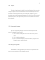
3.4
Comparison Methodologies
43
3.5
Phases Of Parallel Development
43
3.5.1
Planning
44
3.5.2
Analysis
45
3.5.2.1
Programming Language
45
3.5.2.2
Encryption Algorithm
45
3.5.2.3
Network Protocol
46
3.5.3
Design
46
3.5.4
Implementation
47
3.6
Hardware Requirement
47
3.7
Software requirement
48
3.8
Input and Output Specification
48
3.8.1
Input Specification
48
3.8.2
Output specification
49
3.9
CHAPTER 4
Conclusion
Project assumption
49
SYSTEM ARCHITECTURE AND DESIGN
50
4.1
Introduction
50
4.2
System Architecture Design
51
4.3
System Overview
52
4.4
Unified Modeling Language
55
4.4.1
Use case Diagram
55
4.4.2
Sequence Diagram
56
ix
4.5
CHAPTER 5
User Interface Design
58
4.5.1
59
Buttons and Text field Functions
SYSTEM IMPLEMENTATION
60
5.1
Introduction
60
5.2
Java Network Programming
61
5.2.1
Command-Line Arguments
61
5.2.2
Establish Socket Connection
63
5.2.2.1
Client Code For Socket
63
5.2.2.2
Server Code For Socket
63
5.3
Establishing a Security Context
64
5.3.1
Client GSSContext Instantiation
64
5.3.2
Client Context Establishment
65
5.3.3
Server GSSContext Instantiation
66
5.3.4
Server Context Establishment
67
5.4
Login Configuration
68
5.5
Policy Files
69
5.5.1
Client Policy
70
5.5.2
Server Policy
71
5.6
Encryption and Decryption of the Text
Messages
71
5.7
Settings up a Redhat Linux Kerberos Server
72
5.8
Input / Output Data And Result
75
5.8.1
Input/Output Data
75
5.8.1.1 Encryption Input/Output Data
75
5.8.1.2 Decryption Input/Output Data
76
Testing
76
5.8.2.1 Unit Testing
77
5.8.2.2 Integration Testing
78
5.8.2.3 Interface Testing
78
5.8.2
5.9
Summary
79
x
CHAPTER VI
CONCLUSION
80
6.1
Introduction
80
6.2
Advantages
80
6.3
Limitations and Disadvantages
81
6.4
Suggestions for Future Work
81
6.5
Discussion
82
6.6
Conclusion
83
REFERENCE
85
APPENDIX A – B
87
CHAPTER 1
INTRODUCTION
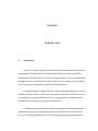
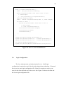
1.1
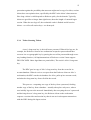
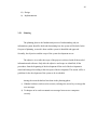
Introduction
In this 21st century, information technology and telecommunications has grown
tremendously. The rapid growth of information technology has made it possible to
communicate efficiently using text messages through networks. These text transactions
through networks are not safe from security threats. There are prone to security threats
such as interruption, interception, modification and fabrication.
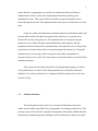
In an ideal world we would all be able to openly send encrypted email or files to
each other. However there are often cases when this is not possible, either because you
are working for a company that does not allow encrypted email or perhaps the local
government does not approve encrypted communication.
Considering these security threats and the importance of information security to
information technology, text transmission in networks should be integrated with the
services provided by information security. The development of text communication
2
system that uses cryptography to secure the text transmission based on Kerberos
Authentication which is on the idea of integrating information technology and
information security. This system is able to transmit encrypted information in text
format through the network. The implementation of this system is divided into two main
parts.
Firstly, the sender will authenticate with the Kerberos key distribution sender and
generate token which will contain encrypted senders and receiver’s symmetric key
which will be used to encrypt the text. The implementation of encryption using the
shared secret key will provide data origin authentication, data integrity, and nonrepudiation for the text that will be transmitted later. Secondly, the receiver will gain the
symmetric-key from the token which is encrypted using his/her master key. During the
transmission, the text message will be encrypted at the senders end and later be
decrypted at the receivers end. The text message is encrypted so that it is concealed from
unauthorized parties.
This system was developed using the JAVA programming language, to make it
cross-platform that is it can be used in many platforms such as Windows and Linux
platforms. To use this system the user’s computer should be connected to a Local Area
Network (LAN).
1.2
Problem Statement
The development of this system is to overcome the limitations of previous
similar systems which using Public Key Cryptographic to exchange symmetric key. The
message sent over the network is exposed to interruption, interception, modification and
fabrication by unauthorized parties (Stallings, 1998). Such threats are hard to be traced,
3
and will cause negative effect on both the sender and receiver. Encryption is the most
effective way to counteract these threats. So, the text will be encrypted before being
transmitted.
The transmission of text over the network makes the parties involved worry
about, the assurance of the source that transmitted the text, and assurance that the text
has not been modified. As an alternative to these worries, the symmetric key will be
used to encrypt the messages.
Kerberos is an Internet Engineering Task Force (IETF) standard that defines a
typical key exchange mechanism. Applications can use the Kerberos service to
authenticate their users and exchange cryptographic keys with them. Kerberos is based
on the idea of tickets. A ticket is just a data structure that wraps a cryptographic key,
along with some other bits of information. A key distribution center (KDC) distributes
Kerberos tickets to authenticated users.
This system can be used to communicate with anybody at regardless of location
and time assuming that both parties wishing to communicate are connected to a LAN or
the Internet.
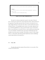
1.3
Project Purpose
The purpose of this project is to develop a system which can be used by
organizations and companies for security purposes and to secure the transmission of text
messages which are transmitted through the network. This purpose of this project also to
develop a system which is easy to use and efficient to secure text messages that are sent
in a chat system and to overcome the public key cryptographic Infrastructure limitation.
4
1.4
Project Objective
Objectives of this project are as follows:
i)
To learn in detail the implementation of Kerberos authentication.
ii)
To implement encryption to secure text transmission using Kerberos
authentication mechanism to exchange encryption key.
iii)
To securely transmit the encrypted text between host to host by creating a
reliable connection using TCP protocol
iv)
To provide data origin authentication, data integrity and confidentiality
for the transmitted text provide by Generic Security Services API (GSSAPI)
v)
To develop a prototype message exchange system using network
programming and cryptography techniques.
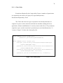
1.5
Project Scope
Scopes of this project are as follows:
i)
The chat system communication can only occur between two hosts at a
time.
ii)
The characters in a message sent will be limited to a maximum of 50
characters.
iii)
The development of this system only emphasizes on providing security
services for the text transmission and to securely exchange the credential
(symmetrical key) between to parties.
iv)
The symmetrical key management will be done using Kerberos
Authentication Mechanism V5 in LINUX platform
5
v)
Every user must be authenticated to the Kerberos server (KDC). The new
user for the Kerberos server is out of scope of this project.
vi)
The development of this system only emphasizes to exchange the
credential using Kerberos V5 authentication mechanism, not
implementing the Kerberos authentication protocol.
vii)
The algorithm used for the encryption technique is the Advanced
Encryption Algorithm (AES).
viii)
The system will be developed using JAVA programming language to
make it cross-platform.
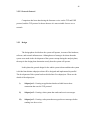
1.6
Justification
This system is done so that chatting system will be more secure than ever. People
can exchange important messages feeling more secured with this system. With this
system, important messages can be transmitted safely and private chatting will have
more privacy. Some users may want to chat with their friends privately and in an
organization, managers may need to exchange important information with their workers
privately. By exchanging messages this way, the messages is guaranteed that an
unauthorized person can’t read it because he only sees an encrypted file being
transferred. So to fulfill their needs, this system was being built.
CHAPTER 2
LITERATURE REVIEW
2.1
Introduction
In this chapter a detailed study is been done on chat system, Kerberos
authentication protocol, encryption system and the techniques to implement it. The
available chat systems and comparisons are explained in this chapter. Methods used
to share the secret key among two hosts which will communicate securely are
explained. An explanation of a few techniques and methods in general are also
explained in this chapter. The suitable methods for Kerberos protocol is selected after
doing research about this detailed study. In this chapter, a research has been done on
the encryption techniques also so that encryption could be implemented. Methods
used to perform the encryption and decryptions are also explained in this chapter.
7
2.2
Chat System
One of the many popular methods of communicating over the network is by
using a text chat system. "Chat" as we usually use the term refers to a room-style
environment where many people can gather as a group and talk to one another. Text
chat system is a text-based communicating system where anyone can connect to a
system where people are discussing a topic, launch a special program that handles
the text messages, and read the messages of the participants immediately or send
immediate messages to the group. Like verbal conversations, once a statement is
made, it soon scrolls off the screens of the participants and is gone forever unless one
of them is recording it. You watch the discussion on your screen, and type in your
own messages whenever you feel like it.
There are many available chat systems that are currently being used. Some of
the available chat systems in a LAN are the Win Messenger and Windows
NetMeeting. Win Messenger is widely used by many users in a LAN environment.
Windows NetMeeting is also widely used for both text and voice communications.
Both of these systems provide the basic needs to communicate with other users using
text messages.
Although there are many chat systems available such as the Win Messenger
and Windows NetMeeting, all of them do not provide extra security features other
than user name and passwords. Even though user name and password need to be
entered in order to use these systems, hackers could retrieve the messages sent
through network by intercepting it. This is one of the problems that these systems
have. The messages sent can also be modified by third party users before it reaches
its destination. This may cause the receiver to receive a different message from the
original message sent.
Because of these problems, extra security features have been implemented in
this project. In order to secure the messages cryptography system are used.
8
2.3
Kerberos Authentication Protocol
The Kerberos protocol relies heavily on an authentication technique involving
shared secrets. The basic concept is quite simple: If a secret is known by only two
people, then either person can verify the identity of the other by confirming that the
other person knows the secret.
For example, let’s suppose that Alice often sends messages to Bob and that
Bob needs to be sure that a message from Alice really has come from Alice before he
acts on its information. They decide to solve their problem by selecting a password,
and they agree not to share this secret with anyone else. If Alice’s messages can
somehow demonstrate that the sender knows the password, Bob will know that the
sender is Alice. The only question left for Alice and Bob to resolve is how Alice will
show that she knows the password. She could simply include it somewhere in her
messages, perhaps in a signature block at the end—Alice, OurSecret. This would be
simple and efficient and might even work if Alice and Bob can be sure that no one
else is reading their mail. Unfortunately, that is not the case. Their messages pass
over a network used by people like Carol, who has a network analyzer and a hobby
of scanning traffic in hope that one day she might spot a password. So it is out of the
question for Alice to prove that she knows the secret simply by saying it. To keep the
password secret, she must show that she knows it without revealing it.
The Kerberos protocol solves this problem with secret key cryptography.
Rather than sharing a password, communication partners share a cryptographic key,
and they use knowledge of this key to verify one another’s identity. For the technique
to work, the shared key must be symmetric—a single key must be capable of both
encryption and decryption. One party proves knowledge of the key by encrypting a
piece of information, the other by decrypting it.
9
2.3.1
Authenticators
A simple protocol that uses secret key authentication begins when someone is
outside a communications door and wants to go in. To gain entry, this person
presents an authenticator in the form of a piece of information encrypted in the
secret key. The information in the authenticator must be different each time the
protocol is executed, otherwise an old authenticator could be reused by anyone who
happens to overhear the communication. On receiving an authenticator, the person
guarding the door decrypts it and knows from what is inside whether decryption was
successful. If it was successful, the doorkeeper knows that the person presenting the
authenticator has the correct key. Only two people have the correct key; the
doorkeeper is one of them, so the person who presented the authenticator must be the
other.
If the person outside the door wants mutual authentication, the same protocol
can be executed in reverse, with a slight difference. The doorkeeper can extract part
of the information from the original authenticator, encrypt it in a new authenticator,
and then give the new authenticator to the person waiting outside the door. The
person outside the door can then decrypt the doorkeeper’s authenticator and compare
the result with the original. If there is a match, the person outside the door will know
that the doorkeeper was able to decrypt the original, so he must have the correct key.
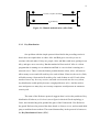
It will help to walk through an example. Suppose Alice and Bob decide that
before transferring any information between their computers, each will use
knowledge of a shared secret key to verify the identity of the party at the other end of
the connection. In situations where Alice is the wary guest and Bob is the suspicious
host, they agree to follow this protocol:
1.
Alice sends Bob a message containing her name in plaintext and an
authenticator encrypted in the secret key she shares with Bob. In this protocol,
the authenticator is a data structure with two fields. One field contains
information about Alice. For simplicity, let’s say this is another instance of her
name. The second field contains the current time on Alice’s workstation.
10
2.
Bob receives the message, sees that it is from someone claiming to be Alice,
and uses the key he shares with Alice to decrypt the authenticator. He extracts
the field that contains the time on Alice’s workstation, and evaluates the time.
Bob’s task will be easier if his clock is reasonably synchronized with Alice’s,
so let’s suppose both Alice and Bob use a network time service to keep their
clocks fairly close. Let’s say the time skew is never more than five minutes.
This way, Bob can compare the time from the authenticator with the current
time on his clock. If the difference is greater than five minutes, he can
automatically reject the authenticator. If the time is within the allowable skew,
it’s probable that the authenticator came from Alice, but Bob still does not have
proof that the authenticator actually came from her. Another person might have
been watching network traffic and might now be replaying an earlier attempt
by Alice to establish a connection with Bob. However, if Bob has recorded the
times of authenticators received from Alice during the past five minutes, he can
defeat attempts to replay earlier messages by rejecting any message with a time
that is the same as or earlier than the time of the last authenticator. If this
authenticator yields a time later than the time of the last authenticator from
Alice, then this message must be from Alice.
3.
Bob uses the key he shares with Alice to encrypt the time taken from Alice’s
message and sends the result back to her. Note that Bob does not send back all
of the information taken from Alice’s authenticator, just the time. If he sent
back everything, Alice would have no way of knowing whether someone
posing as Bob had simply copied the authenticator from her original message
and sent it back to her unchanged. He sends just a piece of the information in
order to demonstrate that he was able to decrypt the authenticator and
manipulate the information inside. He chooses the time because that is the one
piece of information that is sure to be unique in Alice’s message to him. Alice
receives Bob’s reply, decrypts it, and compares the result with the time in her
original authenticator. If the times match, she can be confident that her
authenticator reached someone who knows the secret key needed to decrypt it
and extract the time. She shares that key only with Bob, so it must be Bob who
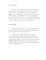
received her message and replied.
11
1
2
Bob
Alice
"I'm Alice", KAB{Alice, timestamp}
4
3
KAB{timestamp}
Figure 2.1: Mutual authentication (Alice-Bob)
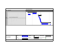
2.3.2
Key Distribution
One problem with the simple protocol described in the preceding section is
that it does not explain how or where Alice and Bob got a secret key to use in
sessions with each other. If they are people, Alice and Bob could meet, perhaps in an
alley, and agree on a secret key. But that method will not work if Alice is a client
program that is running on a workstation and Bob is a service that is running on a
network server. There is also the further problem that the client, Alice, will want to
talk to many servers and will need keys for each of them. Likewise, the service, Bob,
will talk to many clients and will need keys for each of them as well. If each client
needs to have a key for every service, and each service needs one for every client,
key distribution could quickly become a tough problem to solve. And the need to
store and protect so many keys on so many computers would present an enormous
security risk.
The name of the Kerberos protocol suggests how it solves the problem of key
distribution. Kerberos (or Cerberus) was a figure in classical Greek mythology, a
fierce, three-headed dog who guarded the gates of the Underworld. Like Kerberos
the guard, Kerberos the protocol has three heads: a client, a server, and a trusted third
party to mediate between them. The trusted intermediary in the protocol is known as
the Key Distribution Center (KDC).
12
The KDC is a service that runs on a physically secure server. It maintains a
database with account information for all security principals in its realm, the
Kerberos equivalent of a Windows 2000 domain. (We will continue to call them
domains.) Along with other information about each security principal, the KDC
stores a cryptographic key known only to the security principal and the KDC. This
key is used in exchanges between the security principal and the KDC and is known
as a long-term key. In most implementations of the protocol, it is derived from a
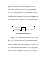
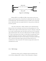
user’s logon password. When a client wants to talk to a server, the client sends a
request to the KDC, and the KDC distributes a unique, short-term session key for the
two parties to use when they authenticate each other. The server’s copy of the session
key is encrypted in the server’s long-term key. The client’s copy of the session key is
encrypted in the client’s long-term key.
KClient {use SCS for Server}
KDC invents
session key
SCS
Server
Client
Client wants Server
KServer {use SCS for Client}
Figure 2.2: Key Distribution (in theory)
In theory, the KDC could fulfill its role as a trusted intermediary by sending
the session key directly to each of the security principals involved, as illustrated
above. But, in practice, that procedure would be extremely difficult to implement.
For one thing, it would mean that the server would have to retain its copy of the
session key in memory while it waited for the client to call. Moreover, the server
would need to remember a key not just for this client but for every client who might
ask for service. Key management would consume considerable resources on the
server and would thus limit its scalability. In addition, given the vagaries of network
traffic, a client’s request for service might reach the server before the KDC’s
message arrived there with the session key. The server would have to suspend its
reply to the client while it waited to hear from the KDC. This would require the
13
server to save state, imposing still another burden on the server’s resources. What
actually happens in the Kerberos protocol is considerably more efficient.
2.3.3
Session Tickets
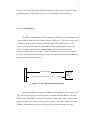
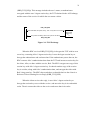
The KDC responds to the client’s request to talk to a server by sending both
copies of the session key to the client, as shown in Figure 3. The client’s copy of the
session key is encrypted with the key that the KDC shares with the client. The
server’s copy of the session key is embedded, along with information about the
client, in a data structure called a session ticket. The entire structure is then
encrypted with the key that the KDC shares with the server. The ticket—with the
server’s copy of the session key safely inside—becomes the client’s responsibility to
manage until it contacts the server.
Client
Client wants Server
KClient {use SCS for Server}, ticket = KServer {use SCS for Client}
KDC invents
session key
SCS
Figure 2.3: Key Distribution (in practice)
Note that the KDC is simply providing a ticket-granting service. It does not
keep track of its messages to make sure they reach the intended address. No harm
will be done if the KDC’s messages fall into the wrong hands. Only someone who
knows the client’s secret key can decrypt the client’s copy of the session key. Only
someone who knows the server’s secret key can read what is inside the ticket.
14
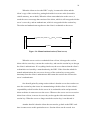
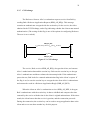
When the client receives the KDC’s reply, it extracts the ticket and the
client’s copy of the session key, putting both aside in a secure cache (located in
volatile memory, not on disk). When the client wants admission to the server, it
sends the server a message that consists of the ticket, which is still encrypted with the
server’s secret key, and an authenticator, which is encrypted with the session key.
The ticket and authenticator together are the client’s credentials to the server.
Client
Server
SCS{Client, time}, ticket = KServer {use SCS for Client}
SCS{time}
Figure 2.4: Mutual authentication (Client/server)
When the server receives credentials from a client, it decrypts the session
ticket with its secret key, extracts the session key, and uses the session key to decrypt
the client’s authenticator. If everything checks out, the server knows that the client’s
credentials were issued by a trusted authority, the KDC. If the client has asked for
mutual authentication, the server uses its copy of the session key to encrypt the
timestamp from the client’s authenticator and returns the result to the client as the
server’s authenticator.
One benefit gained by using session tickets is that the server does not have to
store the session key that it uses in communicating with this client. It is the client’s
responsibility to hold a ticket for the server in its credentials cache and present the
ticket each time it wants access to the server. Whenever the server receives a session
ticket from a client, it can use its secret key to decrypt the ticket and extract the
session key. When the server no longer needs the session key, it can discard it.
Another benefit is that the client does not need to go back to the KDC each
time it wants access to this particular server. Session tickets can be reused. As a
15
precaution against the possibility that someone might steal a copy of a ticket, session
tickets have an expiration time, specified by the KDC in the ticket’s data structure.
How long a ticket is valid depends on Kerberos policy for the domain. Typically,
tickets are good for no longer than eight hours, about the length of a normal logon
session. When the user logs off, the credentials cache is flushed and all session
tickets—as well as all session keys—are destroyed.
2.3.4
Ticket-Granting Tickets
A user’s long-term key is derived from a password. When Alice logs on, for
example, the Kerberos client on her workstation accepts her password and then
converts it to a cryptographic key by passing the text of the password through a oneway hashing function. (All implementations of Kerberos version 5 must support
DES-CBC-MD5. Other algorithms are permissible.) The result is Alice’s long-term
key.
The KDC gets its copy of Alice’s long-term key from her record in its
account database. When it receives a request from the Kerberos client on Alice’s
workstation, the KDC searches its database for Alice, pulls up her account record,
and takes her long-term key from a field in the record.
This process—computing one copy of the key from a password, fetching
another copy of the key from a database—actually takes place only once, when a
user initially logs on to the network. Immediately after accepting the user’s password
and deriving the user’s long-term key, the Kerberos client on the workstation
requests a session ticket and session key that it can use in subsequent transactions
with the KDC during this logon session.
16
The KDC responds to the client’s request by returning a session ticket for
itself. This special session ticket is called a ticket-granting ticket (TGT). Like an
ordinary session ticket, a TGT contains a copy of the session key that the service (in
this case the KDC) will use in communicating with the client. The message that
returns the TGT to the client also includes a copy of the session key that the client
can use in communicating with the KDC. The TGT is encrypted in the KDC’s longterm key. The client’s copy of the session key is encrypted in the user’s long-term
key.
When the client receives the KDC’s reply to its initial request, it uses its
cached copy of the user’s long-term key to decrypt its copy of the session key. It can
then discard the long-term key derived from the user’s password, for it is no longer
needed. In all subsequent exchanges with the KDC, the client uses the session key.
Like any other session key, this key is temporary, valid only until the TGT expires or
the user logs off. For that reason, it is called a logon session key.
From the client’s point of view, a TGT is just another ticket. Before it
attempts to connect to any service, the client first checks its credentials cache for a
session ticket to that service. If it does not have one, it checks the cache again for a
TGT. If it finds a TGT, the client fetches the corresponding logon session key from
the cache, uses this key to prepare an authenticator, and sends both the authenticator
and the TGT to the KDC, along with a request for a session ticket for the service. In
other words, gaining admission to the KDC is no different from gaining admission to
any other service in the domain—it requires a session key, an authenticator, and a
ticket (in this case, a TGT). From the KDC’s point of view, TGTs allow it to shave a
few nanoseconds off the turnaround time for ticket requests. The KDC looks up the
user’s long-term key only once, when it grants an initial TGT. For all other
exchanges with this client, the KDC can decrypt the TGT with its own long-term
key, extract the logon session key, and use that to validate the client’s authenticator.
17
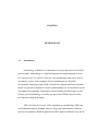
2.3.5
Authentication Across Domain Boundaries
The functions of the KDC are divided into two distinct services: an
authentication service whose job is to issue TGTs, and a ticket-granting service
whose job is to issue session tickets. This division of labor allows the Kerberos
protocol to operate across domain boundaries. A client can get a TGT from the
authentication service of one domain and use it to get session tickets from the ticketgranting service of another domain.
To see how cross-domain authentication works, let’s first consider the
simplest case: a network with only two domains, East and West. If administrators for
these domains are members of the same organization, or if for some other reason
they are willing to treat the other domain’s users as their own, they can enable
authentication across domain boundaries simply by sharing an inter-domain key. (In
Windows 2000 this happens automatically when two domains establish a trust
relationship.) Once this is accomplished, the ticket-granting service of each domain
is registered as a security principal with the other domain’s KDC. As a result, the
ticket-granting service in each domain can treat the ticket-granting service in the
other domain as just another service, something for which properly authenticated
clients can request and receive session tickets.
When a user with an account in East wants access to a server with an account
in West, the Kerberos client on the user’s workstation sends a request for a session
ticket to the ticket-granting service in the user’s account domain, East. The ticketgranting service in East sees that the desired server is not a security principal in its
domain, so it replies by sending the client a referral ticket. This is simply a TGT
encrypted with the inter-domain key that the KDC in East shares with the KDC in
West. The client uses the referral ticket to prepare a second request for a session
ticket, and this time sends the request to the ticket-granting service in the server’s
account domain, West. The ticket-granting service in West uses its copy of the interdomain key to decrypt the referral ticket. If decryption is successful, it sends the
client a session ticket to the desired server in its domain.
18
The referral process is more complicated on networks with more than two
domains. In theory, the KDC in each domain could establish a direct link to the KDC
in every other domain on the network, in each case sharing a different inter-domain
key. In practice, the number and complexity of these relationships could easily
become unmanageable, especially on a large network. The Kerberos protocol solves
the problem by making direct links unnecessary. A client in one domain can get a
ticket to a server in another domain by traveling a referral path through one or more
intermediate domains.
For example, consider a network with three domains, East, West, and PJ. The
KDC in East does not share an inter-domain key with the KDC in West, but both
East and West do share inter-domain keys with PJ. In this case, when a user with an
account in East wants access to a server with an account in West, the referral path
begins at the KDC for the user’s account domain, East, passes through an
intermediate domain, PJ, and ends at the KDC for the server’s account domain, West.
The client must send its request for a session ticket three times, to three different
KDCs.
1. The client asks the KDC for East to give it a ticket to the server in West.
The KDC for East sends the client a referral ticket to the KDC for PJ. This
ticket is encrypted in the inter-domain key East shares with PJ.
2. The client asks the KDC for PJ to give it a ticket to the server in West.
The KDC for PJ sends the client a referral ticket to the KDC for West. This
ticket is encrypted in the inter-domain key PJ shares with West.
3. The client asks the KDC for West to give it a ticket to the server in West.
19
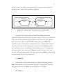
2.3.5.1 Sub-protocols
The Kerberos protocol is comprised of three sub protocols. The sub protocol
in which the KDC gives the client a logon session key and a TGT is known as the
Authentication Service (AS) Exchange. The sub protocol in which the KDC
distributes a service session key and a session ticket for the service is known as the
Ticket-Granting Service (TGS) Exchange. The sub protocol in which the client
presents the session ticket for admission to a service is called the Client/Server (CS)
Exchange. To see how the three sub protocols work together, let’s look at how Alice,
a user at a workstation, gets access to Bob, a service on the network.
2.3.5.2 AS Exchange
Alice begins by logging on to the network. She types her logon name and her
password. The Kerberos client on Alice’s workstation converts her password to an
encryption key and saves the result in its credentials cache.
The client then sends the KDC’s authentication service a Kerberos
Authentication Service Request (KRB_AS_REQ). The first part of this message
identifies the user, Alice, and the name of the service for which she is requesting
credentials, the ticket-granting service. The second part of the message contains preauthentication data that proves Alice knows the password. This is usually a
timestamp encrypted with Alice’s long-term key, although the protocol permits other
forms of pre-authentication data.
20
KRB_AS_REQ
Alice
Alice wants TGS, KAlice{Alice, time}
KAlice{use SAlice for TGS}, TGT = KTGS{use SAlice for Alice}
KDC
AS invents
session key
SAlice
KRB_AS_REP
Figure 2.5: AS Exchange
When the KDC receives KRB_AS_REQ, it looks up the user Alice in its
database, gets her long-term key, decrypts the pre-authentication data, and evaluates
the timestamp inside. If the timestamp passes the test, the KDC can be assured that
the pre-authentication data was encrypted with Alice’s long-term key and thus that
the client is genuine.
After it has verified Alice’s identity, the KDC creates credentials that the
Kerberos client on her workstation can present to the ticket-granting service. First,
the KDC invents a logon session key and encrypts a copy of it with Alice’s long-term
key. Second, it embeds another copy of the logon session key in a TGT, along with
other information about Alice such as her authorization data. The KDC encrypts the
TGT with its own long-term key. Finally, it sends both the encrypted logon session
key and the TGT back to the client in a Kerberos Authentication Service Reply
(KRB_AS_REP).When the client receives the message, it uses the key derived from
Alice’s password to decrypt her logon session key and stores the key in its
credentials cache. Then it extracts the TGT from the message and stores that in its
credentials cache as well.
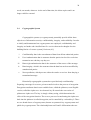
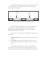
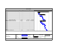
2.3.6 TGS Exchange
The Kerberos client on Alice’s workstation requests credentials for the
service Bob by sending the KDC a Kerberos Ticket-Granting Service Request
21
(KRB_TGS_REQ). This message includes the user’s name, an authenticator
encrypted with the user’s logon session key, the TGT obtained in the AS Exchange,
and the name of the service for which the user wants a ticket.
KRB_TGS_REQ
Alice
Alice wants Bob, SAlice{Alice, time}, TGT = KTGS{use SAlice for Alice}
SAlice{use SAB for Bob}, ticket = KBob{use SAB for Alice}
KDC
TGS invents
session key
SAB
KRB_TGS_REP
Figure 2.6: TGS Exchange
When the KDC receives KRB_TGS_REQ, it decrypts the TGT with its own
secret key, extracting Alice’s logon session key. It uses the logon session key to
decrypt the authenticator and evaluates that. If the authenticator passes the test, the
KDC extracts Alice’s authorization data from the TGT and invents a session key for
the client, Alice, to share with the service, Bob. The KDC encrypts one copy of this
session key with Alice’s logon session key. It embeds another copy of the session
key in a ticket, along with Alice’s authorization data, and encrypts the ticket with
Bob’s long-term key. The KDC then sends these credentials back to the client in a
Kerberos Ticket-Granting Service Reply (KRB_TGS_REP).
When the client receives the reply, it uses Alice’s logon session key to
decrypt the session key to use with the service, and stores the key in its credentials
cache. Then it extracts the ticket to the service and stores that in its cache.
22
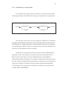
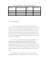
2.3.7 CS Exchange
The Kerberos client on Alice’s workstation requests service from Bob by
sending Bob a Kerberos Application Request (KRB_AP_REQ). This message
contains an authenticator encrypted with the session key for the service, the ticket
obtained in the TGS Exchange, and a flag indicating whether the client wants mutual
authentication. (The setting of this flag is one of the options in configuring Kerberos.
The user is never asked.)
SAB{Alice, time}, ticket = KBob{use SAB for Alice}
Bob (server)
Alice (client)
KRB_AP_REQ
SAB{time}
KRB_AP_REP
Figure 2.7: CS Exchange
The service, Bob, receives KRB_AP_REQ, decrypts the ticket, and extracts
Alice’s authorization data and the session key. Bob uses the session key to decrypt
Alice’s authenticator and then evaluates the timestamp inside. If the authenticator
passes the test, Bob looks for a mutual authentication flag in the client’s request. If
the flag is set, he uses the session key to encrypt the time from Alice’s authenticator
and returns the result in a Kerberos Application Reply (KRB_AP_REP).
When the client on Alice’s workstation receives KRB_AP_REP, it decrypts
Bob’s authenticator with the session key it shares with Bob and compares the time
returned by the service with the time in the client’s original authenticator. If the times
match, the client knows that the service is genuine, and the connection proceeds.
During the connection, the session key can be used to encrypt application data or the
client and server can share another key for this purpose.
23
2.3.8
Tickets
So far we have avoided a detailed description of exactly what is in a ticket,
how expiration times are calculated, and how much of a ticket’s content is known by
the client. All of these details are important to understanding how to configure
Kerberos policy, and so they deserve a closer look.
2.3.8.1 What Is in a Ticket
For our purpose here, it is enough to list the fields in a ticket and to describe
the information they contain. The exact data structures for tickets as well as
messages can be found in RFC 1510.
24
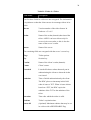
Table2.1: Fields of a Ticket
Field Name
Description
The first three fields in a ticket are not encrypted. The information
is in plaintext so that the client can use it to manage tickets in its
cache.
tkt-vno
Version number of the ticket format. In
Kerberos v.5 it is 5.
Realm
Name of the realm (domain) that issued the
ticket. A KDC can issue tickets only for
servers in its own realm, so this is also the
name of the server’s realm.
Sname
Name of the server.
The remaining fields are encrypted with the server’s secret key.
Flags
Ticket options.
Key
Session key.
Crealm
Name of the client’s realm (domain).
Cname
Client’s name.
Transited
Lists the Kerberos realms that took part in
authenticating the client to whom the ticket
was issued.
Authtime
Time of initial authentication by the client.
The KDC places a timestamp in this field
when it issues a TGT. When it issues tickets
based on a TGT, the KDC copies the
authtime of the TGT to the authtime of the
ticket.
Starttime
Time after which the ticket is valid.
Endtime
Ticket’s expiration time.
renew-till
(Optional) Maximum endtime that may be set
in a ticket with a RENEWABLE flag.
25
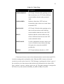
Table 2.2: Ticket Flags
Flag
Description
FORWARDABLE
(TGT only) Tells the ticket-granting service
that it can issue a new TGT with a different
network address based on the presented
TGT.
FORWARDED
Indicates either that a TGT has been
forwarded or that a ticket was issued from a
forwarded TGT.
PROXIABLE
(TGT only) Tells the ticket-granting service
that it can issue tickets with a different
network address than the one in the TGT.
PROXY
Indicates that the network address in the
ticket is different from the one in the TGT
used to obtain the ticket.
RENEWABLE
Used in combination with the endtime and
renew-till fields to cause tickets with long
life spans to be renewed at the KDC
periodically.
INITIAL
(TGT only) Indicates that this is a TGT.
Clients need to know some of the information that is inside tickets and TGTs
in order to manage their credentials cache. When the KDC returns a ticket and
session key as the result of an AS or TGS Exchange, it packages the client’s copy of
the session key in a data structure that includes the information in the ticket fields
flags, authtime, starttime, endtime, and renew-till. The entire structure is encrypted in
the client’s key and returned with KRB_AS_REP or KRB_TGS_REP.
26
2.3.8.2 KDC Ticket’s Lifetime
Tickets have a start time and an expiration time. At any time after the start
time but before the expiration time, a client holding a ticket for a service can present
the ticket and gain access to the service, no matter how many times the client has
used the ticket before. In order to reduce the risk that a ticket or the corresponding
session key may be compromised, administrators can set the maximum lifetime for
tickets. This time is an element of Kerberos policy.
When a client asks the KDC for a ticket to a service, it may request a specific
start time. If this time is missing from the request or is a time in the past, the KDC
sets the ticket’s starttime field to the current time.
Whether or not clients specify a start time, their requests must include a
desired expiration time. The KDC determines the value of a ticket’s endtime field by
adding the maximum ticket life fixed by Kerberos policy to the value of the ticket’s
starttime field. It then compares the result with the requested expiration time.
Whichever time is sooner becomes the ticket’s endtime.
2.3.8.3 Tickets Expire
The KDC does not notify clients when session tickets or TGTs are about to
expire. In fact, it makes no effort to keep track of transactions with clients beyond
short-term records needed to prevent replay attacks.
If a client presents an expired session ticket when requesting a connection to
a server, the server returns an error message. The client must request a new session
ticket from the KDC. Once a connection is authenticated, however, it no longer
matters whether the session ticket remains valid. Session tickets are used only to
authenticate new connections with servers. Ongoing operations are not interrupted if
the session ticket used to authenticate the connection expires during the connection.
27
If a client presents an outdated TGT when requesting a session ticket from the
KDC, the KDC responds with an error message. The client must request a new TGT,
and to do that it needs the user’s long-term key. If the client did not cache the user’s
long-term key during the initial logon process, the client may have to ask the user for
a password and derive the long-term key.
2.3.8.4 Renewable TGTs
One defense against attacks on session keys is to force them to change often
by setting Kerberos policy so that maximum ticket life is relatively short. Another is
to allow renewable tickets. When tickets are renewable, session keys are refreshed
periodically without issuing a completely new ticket. If Kerberos policy permits
renewable tickets, the KDC sets a RENEWABLE flag in every ticket it issues and
sets two expiration times in the ticket. One expiration time limits the life of the
current instance of the ticket. A second expiration time sets a limit on the cumulative
lifetime of all instances of the ticket.
The expiration time for the current instance of the ticket is held in the endtime
field. As with non-renewable tickets, endtime is the value of the starttime field plus
the maximum ticket life specified by Kerberos policy. A client holding a renewable
ticket must send it to the KDC for renewal before the endtime is reached, presenting
a fresh authenticator as well. When the KDC receives a ticket for renewal, it checks a
second expiration time held in the renew-till field. This time is set when the ticket is
first issued, and the value is the ticket’s starttime plus the maximum cumulative
ticket life specified by Kerberos policy. When the KDC renews the ticket, it checks
to see that the renew-till time has not yet arrived. If it has not, the KDC issues a new
instance of the ticket with a later endtime and a new session key.
This means that administrators can set Kerberos policy so that tickets must be
renewed at relatively short intervals—every day, perhaps. When tickets are renewed,
a new session key is issued, minimizing the value of a compromised key.
Administrators can also set cumulative ticket life for a relatively long period—one
28
week, one month, whatever. At the end of that time, the ticket expires and is no
longer valid for renewal.
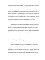
2.4
Cryptographic System
Cryptographic systems (or cryptosystems) potentially provide all the three
objectives of information security: confidentiality, integrity, and availability. In order
to clarify and demonstrate how cryptosystems are employed, confidentiality and
integrity are further sub-classified into five services that can be thought of as the
building blocks of a secure system [Certicom, 00]:
i.
Confidentiality that is the concealment of data from all but authorized parties.
ii.
User Authentication that is assurance that the parties involved in a real-time
transaction are who they say they are.
iii.
Data origin authentication that is the assurance of the source of the message.
iv.
Data integrity, which is the assurance that the data has not been modified by
unauthorized parties.
v.
Non-repudiation, which prevents either the sender or receiver from denying a
transmitted message.
Historically cryptographic systems have provided only confidentiality.
Preparing a message for a secure, private transfer involves the process of encryption.
Encryption transforms data in user readable form, called the plaintext, to an illegible
version, called the cipher text. An electronic key K controls the conversion of
plaintext to cipher text. The key is simply a binary string, which determines the
effect of the encryption function. The reverse process of transforming the cipher text
back into the plaintext is called decryption, and is controlled by a related key L.There
are two broad classes of cryptosystems, known as symmetric-key cryptosystems and
public-key cryptosystems. The relationship between K and L differentiates the two.
29
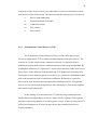
2.4.1
Symmetric-key Cryptosystems
In a symmetric-key cryptosystems, the same key is used for both encryption
and decryption. Figure 2.8 illustrates the analogy of a symmetric-key cryptosystems.
Plaintext
Secret-key K
Cipher text
Sender
Secret-key K
Plaintext
Receiver
Figure 2.8: Analogy of a Symmetric-key Cryptosystems
Since the keys are the same, two users wishing to communicate in confidence
must agree and maintain a common secret key. Each entity must trust each other not
to divulge the key. In applications where a limited number of users exist, symmetrickey cryptography is effective. However, in large networks with users distributed over
a wide area, key distribution becomes a problem.
Symmetric-key cryptosystems have been used to provide confidentiality for
thousands of years. One of the first recorded systems was used by Julius Caesar.
Known as the Caesar Cipher, it involves shifting the letters of the alphabet a
predetermined number of characters. The number of character shifts is the encryption
key, and, of course, shifting back the same number of characters reverses this process
to decrypt. Nowadays, keys that are based on complex mathematical algorithms
control symmetric-key cryptosystems. Examples of symmetric-key cryptosystems
are DES, IDEA and RIJNDAEL.
30
2.4.1.1 Implementation of the RIJNDAEL Algorithm
The RIJNDAEL cryptography has been chosen to encrypt the compressed
audio stream that will be transmitted over the network. The RIJNDAEL algorithm
will be used because of its’ criteria such as:
i.
RIJNDAEL can be implemented very efficiently on a wide range of
processors and in hardware.
ii.
RIJNDAEL uses keys with a length of 128, 192, or 256 bits to encrypt blocks
with a length of 128, 192 or 256 bits (all nine combinations of key length and
block length are possible).
iii.
The block length and key length can be extended very easily to multiples of
32 bits
iv.
It is suitable to encrypt audio streams.
v.
The encryption and decryption time consumed by the RIJNDAEL is fast
enough for real-time application.
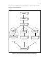
2.4.2
Asymmetric-key Cryptosystems
Asymmetric-key cryptosystems are contemporary technology, introduced as
recently as 1976 by two Stanford researchers, Whitfield Diffie and Martin Hellman.
In an asymmetric-key cryptosystems, the abilities to perform encryption and
decryption are separated. The encryption rule employs a public key E, while the
decryption rule requires a different (but mathematically related) private key D.
Knowledge of the public key allows encryption of plaintext but does not allow
decryption of the cipher text. If a person selects and publishes their public key, then
everyone can use that one public key to encrypt messages for that person. The private
key is kept secret so that only the intended individual can decrypt the cipher text.
31
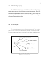
Figure 2.9 shows the analogy of an asymmetric-key cryptosystems. Examples of
asymmetric-key cryptosystems are RSA and Elgamal.
Public key
Plaintext
Asymmetric
cipher
Private key
Ciphertext
Asymmetric
cipher
Plaintext
Figure 2.9: Analogy of an Asymmetric-key Cryptosystems
Asymmetric-key cryptosystems are capable of fulfilling all the main
objectives of information security. For illustrative purposes, each service is discussed
in the context of a hypothetical communication between two users, Alice and Bob.
Bob’s private key will be denoted by Dbob and his public key by Ebob. The
adversary, trying to subvert secure communication, is Eve. Suppose Alice wishes to
send a secret message to Bob. During system set-up, Bob makes Ebob, his public
key, available to all users by publishing it in the public directory. To communicate
message M to Bob, Alice first looks up Ebob in the public directory. Alice then
encrypts M by performing the public-key transformation using Ebob, to transform M
into ciphertext C. This process is denoted by:
C = Ebob (M)
Finally Alice sends C to Bob. Bob retrieves M by transforming C using
Dbob. Alice and Bob are now assured that no one else can decipher C, since only
Bob knows his private key, Dbob. Therefore Bob alone can compute:
M = Dbob (C)
32
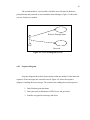
Thus performing asymmetric-key encryption in this way provides the service
of confidentiality. Figure 2.10 illustrates the procedure Alice and Bob undergo
during asymmetric-key encryption.
Bob’s
Public
key
Bob’s
Private
key
Alice
Bob
Plaintext
Encryption
Ciphertext
Decryptio
Plaintext
Figure 2.10: How Asymmetric-key Encryption Works
While the message is confidential, there is no assurance that the message
came from Alice. A method for achieving the extra service of data origin
authentication, data integrity and non-repudiation is by implementing digital
signature using asymmetric-key encryption.
In broad terms, we can classify the use of asymmetric-key cryptosystem into
three categories:
i.
Encryption/decryption: The sender encrypts a message with the recipient’s
public key.
ii.
Key exchange: two sides cooperate to exchange a session key. Several
different approaches are possible, involving the private keys of one or both
parties.
Some asymmetric-key algorithms are suitable for all three applications,
whereas others can be used only for one or two of these applications. Table 2.10
shows the applications supported by the RSA, Diffie-Hellman, and DSS algorithm.
33
Table 2.3 Applications for Asymmetric-key Cryptosystem
Algorithm
Encryption/decryption Digital
Key Exchange
Signature
RSA
Yes
Yes
Yes
Diffie-Hellman
No
No
Yes
DSS
No
Yes
No
2.5
Network protocols
Two entities cannot just send bit streams to each other and expect to be
understood. For this communication to occur, protocols are used. Protocol is a set of
rules that is used in communication process through the network. It’s a set of rules
that has been agreed by many different parties so that the communication between
them can work. For communication to occur, the two entities must agree on one
protocol. The end user can control the quality of data in the Transmission Control
Protocol/Internetworking Protocol (TCP/IP) layer by choosing the better and more
efficient end to end protocol.
The TCP/IP is a set of protocols, or a protocol suite, that defines how all
transmissions are exchanged across the network (LAN, MAN or WAN).
Transmission Control Protocol (TCP) was developed before the OSI model.
Therefore, the layers in the TCP/IP protocol do not match exactly with those in the
OSI model. The TCP/IP protocol is made of five of five layers: physical, data link,
network, transport, and application. The application layer in TCP/IP can be equated
with the combination of session, presentation, and application layers of the OSI
model.
At the transport layer, TCP/IP defines two protocols: TCP and User
Datagram Protocol (UDP). The transport layer is very significant to this system
34
compared to other layers because it is responsible for source-to-destination (end-toend) delivery of the audio stream. The functions that the transport layer provides are:
2.5.1
i)
Service-point addressing
ii)
Segmentation and reassembly
iii)
Connection control
iv)
Flow control
v)
Error control
Transmission Control Protocol (TCP)
The Transmission Control Protocol (TCP) provides full transport layer
services to applications. TCP is reliable stream transport port-to-port protocol. The
term stream, in this context means connection-oriented: a connection must be
established between both ends of a transmission before either may transmit data. By
creating this connection, TCP generates a virtual circuit between sender and receiver
that is active for the duration of the transmission. TCP begins each transmission by
alerting the receiver that data grams are on their way (connection establishment) and
ends each transmission with a connection termination. Reliability is ensured by
provision for error detection and retransmission of damaged frames; all segments
must be received and acknowledged before the transmission is considered complete
and virtual circuit is discarded.
At the sending of each transmission, TCP divides long transmission into
smaller data units and packages each into a frame called a segment. Each segment
includes a sequencing number for reordering after receipt. At the receiving end, TCP
collects each datagram as it comes in and reorders the transmission based on
sequence numbers.
35
In this project, TCP is chosen because it avoids the lost of packets. TCP also
is a very reliable protocol compared to UDP. It also does error detection and
retransmission of damaged frames.
2.5.2
User Datagram Protocol (UDP)
The UDP provides uncertain connectionless transmission of data across an IP
network. Both TCP and UDP split data into packets called data grams. However TCP
includes extra headers in the datagram to enable retransmission of lost packets and
reassembly of packets into the correct order if they arrive out of order. UDP does not
provide this. If a UDP packet is lost, it's lost. It will not be retransmitted. Similarly,
packets appear in the receiving program in the order they were received, not
necessarily in the order they were sent.
UDP can be up to three times faster than TCP; and there are many
applications for which reliable transmission of data is not nearly as important as
speed. For example lost or out of order packets may appear as static in an audio or
video feed, but the overall picture or sound could still be intelligible. Communicating
using UDP or TCP can be treated like communicating using telephone or mail.
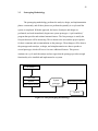
2.6
Java Authentication and Authorization Service (JAAS)
JAAS is a pluggable framework and programming interface specifically
targeted for authentication and access control based on the authenticated identities.
The JAAS framework can be divided into two components: an authentication
component and an authorization component.
36
The JAAS authentication component provides the ability to reliably and
securely determine who is currently executing Java code, regardless of whether the
code is running as an application, an applet, a bean, or a servlet.
The JAAS authorization component supplements the existing Java security
framework by providing the means to restrict the executing Java code from
performing sensitive tasks, depending on its source code and depending on who is
executing the code.
2.7
Java Generic Security Service Application Program Interface
Enterprise applications often have varying security requirements and deploy a
range of underlying technologies to achieve this. In such a scenario how do we
develop a client-server application so that it can easily migrate from one technology
to another? The GSS-API was designed in the Common Authentication Technology
working group of the IETF to solve this problem by providing a uniform application
programming interface for peer to peer authentication and secure communication that
insulates the caller from the details of the underlying technology.
The API, described in a language independent form in RFC 2743 [5],
accommodates the following security services: authentication, message
confidentiality and integrity, sequencing of protected messages, replay detection, and
credential delegation. The underlying security technology or "security mechanism"
being used, has a choice of supporting one or more of these features beyond the
essential one way authentication 1. There are mainly two standard security
mechanisms that the IETF has defined: Kerberos V5 [5] and the Simple Public Key
Mechanism (SPKM) [6].
The API is designed such that an implementation may support multiple
mechanisms simultaneously, giving the application the ability to choose one at
37
runtime. Mechanisms are identified by means of unique object identifier's (OID's)
that are registered.
Another important feature of the API is that it is token based. i.e., Calls to the
API generate opaque octets that the application must transport to its peer. This
enables the API to be transport independent.
The Java API for the Generic Security Service was also defined at the IETF
and is documented in RFC 2853 [7]. Sun is pursuing the standardization of this API
under the Java Community Process (JCP) [7] and plans to deliver a reference
implementation with Merlin. Because the JCP is merely endorsing this externally
defined API, the IETF assigned package namespace "org.ietf.jgss" will be retained in
Merlin. Sun's implementation of Java GSS-API, will initially ship with support for
the Kerberos V5 mechanism only. Kerberos V5 mechanism support is mandatory for
all Java GSS-API implementations in J2SE, although they are free to support
additional mechanisms.
The Java GSS-API framework itself is quite thin, and all security related
functionality is delegated to components obtained from the underlying mechanisms.
The GSSManager class is aware of all mechanism providers installed and is
responsible for invoking them to obtain these components. The GSSManager can be
used to configure new providers and to list all mechanisms already present. The
GSSManager also serves as a factory class for three important interfaces: GSSName,
GSSCredential, and GSSContext.
2.8
Chatting softwares that are currently available
Briefly, softwares that provide text base message exchange system that are
currently in the market are:
38
i)
LAN Messenger 1.1
- Suitable for applications using Windows 95/98/NT.
- Doesn’t provide any security features.
- Suitable for small group of people.
ii)
Win Messenger 2.1
- Suitable for applications using Windows 95/98/NT.
- Doesn’t provide any security features.
iii)
Net Meeting
- Software that provide text base message exchange, system, audio
conference, white board application and application haring facility.
- Doesn’t provide any security features
2.9
Conclusion
All the research that has been done has its own importance. The researches
done on the Kerberos authentication mechanism, allows the suitable method to
securely exchange the credential among two hosts. The Kerberos mechanism has
been chosen to securely exchange the secret key between two hosts and to overcome
the problems with public key crypto system. The AES encryption algorithm was
chosen after a detailed research was done on many algorithms available. The AES
algorithm is a new algorithm and is more secured compared to other algorithms. By
doing this detailed research, it was easier to develop the system.
CHAPTER 3
METHODOLOGY
3.1
Introduction
Methodology is defined as a combination of concept and process to be made a
practical guide. Methodology is a formalized approach to implementing the System
Development Life Cycle (SDLC). There are a few methodologies that can be used in
developing a system. Some examples of these methodologies are Waterfall
Development, Prototyping, Spiral Model, Parallel Development and Object Oriented
Model. In system development it is used for understanding how an information system
can support an organization, designing the system, building and delivering it to user.
Primary goal of methodology is to make sure the system fulfil the objective and is
developed according the planning.
SDLC describes an overview of the component in a methodology. SDLC has
four fundamental phases: planning, analysis, design and implementation. Different
projects may emphasize different approach the SDLC phases in different ways, but all
40
projects have elements of these four phases. Systems development can categorize to two
methodologies that are structure design and Rapid Application Development.
The first category of system development methdologies is structered design.
Structure design methodology appeared in 1980. Structure design methodology are an
approach to developing an information system or software product that is characterized
by a linear sequence of steps that progress from start to finish without revisiting any
previous step. For example waterfall imply that you do each step in sequence. This is the
way most older systems were developed. Examples of structured design methdologies
are Parallel Development and Waterfall Development.In this system, parallel
development methodology is used.
Rapid Application Development (RAD) methodology appeared in 1990 to solve
major problem, which was, assumes in structure design methodology. RAD attempts to
address both weaknesses of the structured development methdologies. This iterative
methodology implies that you do some analysis, then some design and then some
implementation. Based on what you learn, you cycle back through and do more analysis,
design and implementation. This supports human learning a lot better.
3.2
Parallel Development Methodology
Parallel development has been choosen as the methodology to be used in this
system. This methodology attempts to address the problem of long delays between the
analysis phase and the delivery of the system. Instead of doing the design and
implementation in sequence, it performs a general design for the whole system and then
divides the project into a series of distinct subprojects that can be designed and
implemented in parallel. Once all subprojects are complete, there is a final integration of
41
the separate pieces and the system is completed. Figure 3.1 shows the life cycle of the
parallel development methodology.
Planning
Analysis
Design
Design
Implementation
Subproject 1
Design
Design
Implementation
Implementation
Subproject 2
Subproject 3
Implementation
Figure 3.1: Life cycle of the parallel development methodology
42
3.3
Prototyping Methodology
The prototyping methodology performs the analysis, design, and implementation
phases concurrently, and all three phases are performed repeatedly in a cycle until the
system is completed. With this approach, the basics of analysis and design are
performed, and work immediately begins on a system prototype, a “quick-and-dirty”
program that provides and minimal amount features. The first prototype is usually the
first part that user will be interacting. This is shown to the user and the project sponsor
for their comments and recommendation on the prototype. Then changes will be done to
the prototype and reanalyze, redesign, and reimplementation are done to produce a
second prototype, which will have a few more additional features. This process
continues in a cycle until the analyst and user agree that the prototype provides enough
functionality to be installed and implemented as a system.
PLANNING
ANALYSIS
System
DESIGN
IMPLEMENTATION
IMPLEMENTATION
prototype
System
Figure 3.2: The prototyping methodology
43
3.4
Comparison Methodologies
The primary reason this methodology is chosen are :
i)
Parallel development can reduce the schedule time required to complete the
system. Thus there are less chance of changes in the business environment
causing rework.
ii)
Instead of doing the design and implementation in sequence, it performs a
general design for the whole system and then divides the project into a series
of distinct subprojects that can be designed and implemented in parallel.
iii)
The system can be done part by part and therefore the work can be done
systematically.
Problems with prototyping methodologies are :
i)
Its fast-paced system releases challenge attempts to conduct careful,
methodical analysis.
ii)
Often the prototype undergoes such significant changes that many initial
design decisions become poor ones.
iii)
Problems will occur in complex systems development because fundamental
issues and problems are not recognized until well into the development
process.
3.5
Phases Of Parallel Development
The parallel development consist of these phases:
i)
Planning
ii)
Analysis
44
iii) Design
iv) Implementation
3.5.1
Planning
The planning phase is the fundamental process of understanding why an
information system should be built and determining how the system will be built. In the
first part of planning, research is done and the system is identified and approved.
Secondly, the objectives and the scope of the system development are set.
The objective is set after the scope of the project is achieved with all the needed
information and reference. Only after the objective and scope are identified, all the
procedures from the beginning of the development till the end of the development is
stated and arranged according to the time span of the development. This action will be a
guideline for the development of the system to be in schedule.
Among the research that has been done in the planning phase:
i) Whether kerberos can be used to securely exchange the secret key to encrypt the
text messages.
ii) Techniques to be used to transmit text messages between two computers
securely.
45
3.5.2
Analysis
This phase is implemented to identify the needs and limitation of the system that
is being developed. These needs and limitations will be valued and analyzed to ensure
smooth flow in the development of the system. In this phase, emphasis is given in
choosing the most suitable programming language to be used, the most efficient network
authentication protocol , the right network protocol to be used, and the tools needed in
the development.
3.5.2.1 Programming Language
The JAVA programming language will be used in the development of this
system. This language is chosen because:
i) JAVA is robust, meaning that errors in JAVA don’t cause system to
crash.
ii) JAVA is platform independent.
iii) JAVA is a distributed language, which means that it’s programs can be
designed to run on computer networks.
3.5.2.2 Encryption Algorithm
The RIJNDAEL or AES algorithm has been chosen to be implemented in this
system to secure transmission of files through the network.
46
3.5.2.3 Network Protocol
Comparison has been done during the literature review on the TCP and UDP
protocol, and the TCP protocol is chosen because it is most suitable for text over a
network.
3.5.3
Design
The design phase decides how the system will operate, in terms of the hardware,
software, and network infrastructure. Although most of strategic decisions about the
system were made in the development of the system concept during the analysis phase,
the steps in the design phase determine exactly how the system will operate.
In this phase the general design for the whole system is done and then the system
is divided into distinct subprojects that will be designed and implemented in parallel.
The development of this system has been divided into five subprojects. These are the
details of the subprojects:
i)
Subproject 1: Creating an application that has reliable host-to-host
connection that uses the TCP protocol.
ii)
Subproject 2: Creating a chat system that sends and receives messages.
iii)
Subproject 3: Creating a subsystem that encrypts the text messages before
sending it to the receiver.
47
iv)
Subproject 4: Set-up a Kerberos server and client machine to securely
distribute the shared secret key betwen two host.This key will be used to
encrypt the text massenge will be transfered between two host.
v)
Subproject 5: Creating a system that will ritrieve the text messages received
by doing encryption and decryption process at the receiver’s part.
3.5.4
Implementation
The final phase in the parallel development methodology is the implementation
phase, during which the complete subprojects are finally integrated. It is in this phase the
system is actually built. This is the phase that usually gets the most attention, because for
most system it is the longest and most expensive part of the development process.
The first step in implementation is system construction, during which the system
is built and tested to ensure it performs as designed. Testing is one of the most critical
steps in implementation, because the cost of bugs can immense. Once the system has
passed a series of tests, it is installed.
3.6
Hardware Requirements
i) 2 set of personal computer with LAN connection.
ii) 2 Ethernet card
48
3.7
Software Requirements
i) J2SDK 1.4.2_01 as the library for JAVA programming language.
ii) Rational Rose 98 Enterprise Edition to build the use case, sequence
diagrams and class diagrams.
iii) Microsoft Project 2002 to build the Gantt chart.
3.8
Input and Output Specification
To use the system developed in this project several input is required. Those
inputs will be processed to produce output.
3.8.1
Input Specification
For this chat system work it will need several inputs to encrypt and to decrypt.
Valid inputs for encryption are:
i. Text to be encrypted.
ii. Shared Kerberos session key
49
Valid inputs for decryption are:
i. Encrypted text.
ii. Shared Kerberos session key used to encrypt the text.
3.8.2
Output specification
The output produced in this chat system will be the encrypted text or cipher text.
3.9
Project assumption
Through research and analysis performed, if this project is done according to the
work plan, it is assumed that this project will be successful. It is because research is
done in the early stages and with the help of supervisor.
CHAPTER 4
DESIGN
4.1
Introduction
The design phase has of two levels, the first one is constructing the system
design and the second is constructing the user interface design. The system design
consists of the system functional design, system data flow control design and system
protocol design. Meanwhile, the design for user interface involves generating graphical
user interface for the system. These graphical user interfaces function as the middle tier
between the user and the system.
The Unified Modeling Language (UML) method is used in constructing the
object oriented system development; this is done at the system design level. The Use
Case View and Logical View of the UML language will be used to bring up the system
design.
Java Network Programming concept is used to build most part of core program.
It is used to develop and establish connection among hosts in this system. Besides that,
51
sending and receiving messages from one host to another also relies greatly on stream
concept proposed in Java Network Programming.
The Java Swing will be used to construct user interface level. Graphical user
interfaces will be generated on user friendly basis, this is so that the system is easy to
utilize.
4.2
System Architecture Design
First the request for authentication is sent to the krb5kdc daemon. When the
daemon received this request, it looks up the client, the principal, trying to authenticate
in the principal database. It reads the clients secret key from this database and encrypts a
special ticket called a Ticket Granting Ticket (TGT) which it then sends back the client.
The client receives this encrypted TGT which contains a session key. If the client knows
the password (the secret key stored in the principal database) and can successfully
decrypt the TGT, it can present the ticket encrypted with the enclosed session key to a
server, the other user of the system. Through the use of encrypted tickets which can only
be decrypted if the client and server know the secret key, secure authentication takes
place. Once a connection has been established between the server and the client, than the
text messages can be sent and received between them.
52
4.3
System Overview
Figure 4.1 shows the overview of how the system works. This system is only
from one computer to another computer.
(Sender)
(KDC)
Enter Password
(Authenticate to KDC)
(Sender)
Generate Ticket for
Sender and Receiver
share security context
Type text
messages
(Receiver)
Receive encrypted
message
Decrypt the message using
the same secret key
(Receiver)
Encrypt text messages
using the shared secret key
Send
Receive and
display the text
(Receiver)
Figure 4.1: Overview of How the System Works
After establishing a connection, the sender enters his/her password. After that the
text messages to be sent are typed. The amount of messages that can be type is limited.
After typing the message, the sender sends the message by clicking the send button or by
pressing Enter button.
Before transmitting the text messages, the system will encrypt using AES
algorithm .Then, the message will be sent to the receiver.
53
At the receiver’s end, the receiver will receive the encrypted text that was sent by
the sender. The receiver will use the same key to retrieving the plain text message. Only
after that, the receiver will be able to read the text message that was sent. So the text
message that was sent is safe from attacks and is much more secured.
Start
Accept/connect
to other hosts
Type text
messages
Encrypt the text
messages
Sending text
Host sends
to host
yes
Receive text
Host receive
from host
yes
Finish
Figure 4.2: Process of sending messages
54
Figure 4.2 shows an overview of the process of sending messages which is
encrypted using AES algorithm.
Start
Accept/connect
to other hosts
yes
Host receive
from host
Receive text
Read received
text message
Cryptanalysis
Decrypt the
encrypted message
Finish
Figure 4.3: Process of receiving messages
Figure 4.3 shows an overview of the process of receiving a text message and
applying the cryptanalysis process to read the message.
55
4.4
Unified Modeling Language
The Unified Modeling Language, or the UML, is a graphical modeling language
that provides us with syntax for describing the major elements of systems. The use case
model helps us to understand the customer’s requirements, and we can also use the class
diagram to explore the major concepts our customer understands. The sequence diagram
used to show interaction between object.
4.4.1
Use Case Diagram
The first module is show an overview of how the system works. There are three
parts involved in it which are kdc authentication, getting key, communication and the
encryption/decryption part. Figure 4.4 shows the use case diagram for the first module.
KDC Authentication
Getting session key
Encryption
User
Send / Receive
Decryption
Figure 4.4: Use Case for User
56
The second module is a user module, which the user will enter his Kerberos
principal name and password to start communication (chatting). Figure 4.5 shows the
use case for this user module.
Kerberos Principal Name
User
Password
Figure 4.5: Use Case Diagram for User
4.4.2
Sequence Diagram
Sequence diagram shows how objects interact with one another. It also shows the
sequence of how messages are sent and received. Figure 4.6, shows the sequence
diagram of sending the text messages. The scenarios for sending the text messages are:
1. Enter Kerberos principal name.
2. Enter password (Authenticate to KDC Server and get ticket).
3. Send the encrypted text message and ticket.
57
Name
: User
Password
KDC Server
Network
2. Enter name
1. Key in password
Authenticate and getting session key
Encrypt and send massage
Figure 4.6: Sequence diagram sending text message
Figure 4.7, shows the sequence diagram of receiving the text messages. The
scenarios for receiving the text messages are:
1. Receive the encrypted message and ticket contain session key.
2. Get the session key by decrypting the ticket using user master key.
3. Decrypt the message using the session key.
58
: User
Encrypted
message
Decrypt ticket
Plain text
1. Receive text message and ticket
2. Get session key
3. Decrypt encrypted message + ticket
Figure 4.7: Sequence diagram for encrypted text at receiver’s end
4.5
User Interface Design
User interface acts as the upper layer in the system. It is the front-end of the
system, where all the transaction will go through this interface to the back-end of the
system where all the processing is done. The output of the system will be passed through
this interface. It is the medium between the user and the system.
59
Figure 4.8: The Main User Interface for Chatting
4.5.1
Buttons and Text field Functions
1. Send – Send the text message in text box.
2. Exit – To exit from system.
3. Chatting Area – Area for users to chat.
CHAPTER 5
SYSTEM IMPLEMENTATION
5.1
Introduction
This system is developed according to the system design which was defined
in the previous chapter. In the coding phase, the list of classes that are identified will
be coded in Java. The complier being used to develop the system is JDK version
j2sdk1.4.2_01. As a whole, the coding phase consists of writing codes for the clients
to perform Kerberos authentication, network connection and encryption. The
network connection established between these two clients evolves as the base of this
secured communication system. The Kerberos authentication is performed before the
system starts, and the encryption and decryption process is done upon sending and
receiving of the text message.
61
5.2
Java Network Programming
In developing this system knowledge on Java network programming is very
much needed. Knowing the Socket classes and its functions is also very essential to
construct a network based application. Using socket class, a client can establish a
stream-based communications channel with a remote host. To communicate with a
remote host using TCP/IP, the client must first create a Socket to the remote host. To
connect to the host, you must specify the address on the host that you wish to connect
on. There must be a server socket actively listening on the specified port, or the
connection attempt will fail. The methods of class Socket permit identification of the
remote host, and the local and remote port numbers, as well as extraction of streams
for the purposes of bidirectional communication.
In the development of this system, Sockets were used in creating and
establishing network connection between both the clients who wants to commit a
secured text communication. All these messages were transformed into bytes before
being transmitted.
5.2.1
Command-Line Arguments
Client expects three arguments:
i.
A service principal name - The name of the Kerberos principal that represents
Server.
ii.
A host name - The machine on which Server is running.
iii.
A port number - The port number of the port on which Server listens for
connections. Figure 5.1 shows the code for reading the command-line
arguments by client
62
if (args.length < 3) {
System.out.println("Usage: "
+ " <servicePrincipal> <hostName> <port>");
System.exit(-1);
}
String server = args[0];
String hostName = args[1];
int port = Integer.parseInt(args[2]);
Figure 5.1: command-line arguments by client
Server expects just one argument:
i.
A local port number - The port number used by Server for listening for
connections with clients. Figure 5.2 shows the code for reading the
command-line argument by server.
if (args.length != 1) {
System.out.println(
"Usage: <localPort>");
System.exit(-1);
}
int localPort = Integer.parseInt(args[0]);
Figure 5.2: command-line arguments by Server
63
5.2.2
Establish Socket Connection
5.2.2.1 Client Code For Socket Connection
Figure 5.3 shows the client code for the socket connection.
Socket socket = new Socket(hostName, port);
DataInputStream inStream =
new
DataInputStream(socket.getInputStream());
DataOutputStream outStream=new
DataOutputStream(socket.getOutputStream());
Figure 5.3: Client Code for Socket Connection
5.2.2.2 Server Code For Socket Connection
The ServerSocket can then wait for and accept a connection from a client,
and then initialize a DataInputStream and a DataOutputStream for future data
exchanges with the client : Figure 5.4 shows the server code for socket connection.
ServerSocket ss = new ServerSocket(localPort);
Socket socket = ss.accept();
DataInputStream inStream =
new
DataInputStream(socket.getInputStream());
DataOutputStream outStream =
new DataOutputStream(socket.getOutputStream());
System.out.println("Got connection from client " +
socket.getInetAddress());
Figure 5.4: Server Code for Socket Connection
64
5.3
Establishing a Security Context
Before the chat applications can use Java GSS-API to securely exchange
messages between them, they must establish a joint security context using their
credentials. The security context encapsulates shared state information that will
include cryptographic keys. One use of such keys will be to encrypt messages to be
exchanged.
The context initiator (Client) is authenticated to the acceptor (Server), and
may require that the acceptor also be authenticated back to the initiator,for the case
of mutual authentication. Both applications create and use a GSSContext object to
establish and maintain the shared information that makes up the security context. The
Java GSS-API methods exist for preparing tokens to be exchanged between entities
of the chatting applications. After the initiator has received a token from its call to
initSecContext, it sends that token to the acceptor. The acceptor calls
acceptSecContext, passing it the token. The acceptSecContext method may in turn
return a token. Each time initSecContext or acceptSecContext returns a token; the
application that called the method should send the token to its peer and that peer
should pass the token to its appropriate method (acceptSecContext or
initSecContext). This continues until the context is fully established.
5.3.1
Client GSSContext Instantiation
A GSSContext is created by instantiating a GSSManager and then calling
one of its createContext methods. The GSSManager class serves as a factory for
other important GSS API classes. It can create instances of classes implementing the
GSSContext, GSSCredential, and GSSName interfaces. The argument to the
GSSManager createContext method is an Oid representing the Kerberos V5
mechanism to be used for the authentication between the client and the server during
65
context establishment and for subsequent secure communication between them.
Client obtains an instance of the default GSSManager subclass by calling the
GSSManager static method getInstance Figure 5.5 shows the client GSSContext
Instantiation
GSSManager manager = GSSManager.getInstance();
GSSContext createContext(GSSName peer, Oid mech,
GSSCredential myCred, int lifetime);
GSSName createName(String nameStr, Oid nameType);
SampleClient passes the server String for the nameStr
argument.
GSSName serverName = manager.createName(server, null);
Oid krb5Oid = new Oid("1.2.840.113554.1.2.2");
GSSContext context =
manager.createContext(serverName,
krb5Oid,
null,
GSSContext.DEFAULT_LIFETIME);
context.requestMutualAuth(true);
context.requestConf(true);
context.requestInteg(true);
Figure 5.5: Client GSSContext Instantiation
5.3.2
Client Context Establishment
After the Client has instantiated a GSSContext and specified the desired
context options, it can actually establish the security context with Server and a token
generated by a Server call to acceptSecContext. Figure 5.6 shows the client
GSSContext Establishment code.
66
byte[] token = new byte[0];
while (!context.isEstablished()) {
token = context.initSecContext(token, 0, token.length);
if (token != null) {
System.out.println("Will send token of size "
+ token.length + " from initSecContext.");
outStream.writeInt(token.length);
outStream.write(token);
outStream.flush();
}
if (!context.isEstablished()) {
token = new byte[inStream.readInt()];
System.out.println("Will read input token of size "
+ token.length
+ " for processing by initSecContext");
inStream.readFully(token);
}
}
System.out.println("Context Established! ");
System.out.println("Client is " + context.getSrcName());
System.out.println("Server is " + context.getTargName());
if (context.getMutualAuthState())
System.out.println("Mutual authentication took place!");
Figure 5.6: Client Context Establishment
5.3.3
Server GSSContext Instantiation
Like Client, Server obtains an instance of the default GSSManager subclass
by calling the GSSManager static method getInstance. Figure 5.7 shows the
GSSManager factory method for creating a context on the acceptor's side.
67
GSSManager manager = GSSManager.getInstance();
GSSContext createContext(GSSCredential myCred);
GSSContext context = manager.createContext((GSSCredential)null);
Figure 5.7: Server GSSContext Instantiation
5.3.4
Server Context Establishment
After Server has instantiated a GSSContext, it can establish the security
context with Client. To do so, Server has a loop that continues until the context is
established. Each loop iteration does the following:
68
byte[] token = null;
while (!context.isEstablished()) {
token = new byte[inStream.readInt()];
System.out.println("Will read input token of size "
+ token.length
+ " for processing by acceptSecContext");
inStream.readFully(token);
token = context.acceptSecContext(token, 0, token.length);
if (token != null) {
System.out.println("Will send token of size "
+ token.length
+ " from acceptSecContext.");
outStream.writeInt(token.length);
outStream.write(token);
outStream.flush();
}
}
System.out.print("Context Established! ");
System.out.println("Client is " + context.getSrcName());
System.out.println("Server is " + context.getTargName());
if (context.getMutualAuthState())
System.out.println("Mutual authentication took place!");
Figure 5.8: Server Context Establishment
5.4
Login Configuration
The Java Authentication and Authorization Service JAAS login
configuration is required to specify the desired authentication technology. Client and
Server use the same login configuration file, if that file contains two entries, one
entry for the client side and one for the server side. Figure 5.9 shows the client and
the server login configuration file.
69
Client {
com.sun.security.auth.module.Krb5LoginModule required;
};
Server {
com.sun.security.auth.module.Krb5LoginModule required
storeKey=true
principal="prabu/[email protected]";
};
Figure 5.9: The Login Configuration File
The name for each entry matches the respective class names Client and
Server. This name also passed to the Login utility that performs JAAS operations for
the application. That utility expects the name of the entry to be looked up in your
login configuration file to be the same as the name it is passed. Both entries specify
that Sun's Kerberos V5 LoginModule must be used to successfully authenticate the
user. The Krb5LoginModule succeeds only if the attempt to log in to the Kerberos
KDC as a specified entity is successful.The Server entry storeKey=true indicates that
a secret key should be calculated from the password provided during login and it
should be stored in the private credentials of the Subject created as a result of login.
This key is subsequently utilized during mutual authentication when establishing a
security context between Client and Server.
5.5
Policy Files
The policy file used when running Client and Server is server.policy. Their
contents are described below.
70
5.5.1
Client Policy
Permissions Required by the Login utility Classes.A number of permissions
are required by the classes in Login.java (Login and MyAction).
Permissions Required by Client
The Client code does two types of operations for which permissions are
required. It opens a socket connection with the host machine running the Server
application ,initiates establishment of a security context with Server. The permission
required to open a socket connection is permission java.net.SocketPermission "*",
"connect"; Figure 5.10 shows the client policy file.
grant CodeBase "file:./Login.jar" {
permission java.security.AllPermission;
};
grant CodeBase "file:./Client.jar",
Principal javax.security.auth.kerberos.KerberosPrincipal
"bavani/[email protected]" {
permission javax.security.auth.kerberos.ServicePermission
"krbtgt/[email protected]", "initiate";
permission javax.security.auth.kerberos.ServicePermission
"prabu/[email protected]", "initiate";
permission java.net.SocketPermission "*", "connect";};
Figure 5.10: Client. policy
71
5.5.2
Server Policy
Permissions Required by the Login Utility Classes The grant statement in the
server policy file for the Login classes is exactly the same as the one in the client
policy file.Permissions Required by Server are as in Figure 5.11.
grant CodeBase "file:./Login.jar" {
permission java.security.AllPermission;
};
grant CodeBase "file:./Server.jar"
Principal javax.security.auth.kerberos.KerberosPrincipal
"prabu/[email protected]" {
permission java.net.SocketPermission "*", "accept";
permission javax.security.auth.kerberos.ServicePermission
"prabu/[email protected]", "accept";
};
Figure 5.11: Server.policy
5.6
Encryption and Decryption of the Text Messages
The text message is encrypted before send it through network. Encryption is
applied to the message to provide data integrity for the stream that is transmitted. The
encryption and decryption process uses the same symmetrical encryption-key. Figure
5.12 and 5.13 shows the encryption and decryption portion of the coding.
72
try{
String cptxt = null;
AES Ins = new AES(bits/32);
cptxt = Ins.encrypt(mesej,kk,bits);
cptxtbuff = cptxt.doFinal(buff);
byte[] messageBytes = cptxt.getBytes();
MessageProp prop = new MessageProp(0, true);
byte[] token =context.wrap(messageBytes, 0, messageBytes.length, prop);
}
Figure 5.12 : Encrypting the Text Message
try{
byte[] bytes =context.unwrap(token, 0, token.length, prop);
String str = new String(bytes);
AES Ins = new AES(bits/32);
pltxt = Ins.decrypt(str,kk,bits);
pltxtbuff = pltxt.doFinal(buff);
}
Figure 5.13: Decrypting the encrypted text message
5.7
Setting up a Redhat Linux Kerberos Server
With the Redhat 9.0 installation, we ended up with everthing that we needed
to set up a Kerberos server. In particular, we needed the krb5-server RPM:
<root@prabu>:/etc/rc.d/init.d> rpm -a -q | grep krb
krb5-workstation-1.2.4-1
krb5-libs-1.2.4-1
krb5-devel-1.2.4-1
krb5-server-1.2.4-1
krbafs-1.1.1-1
73
pam_krb5-1.55-1
krbafs-devel-1.1.1-1
krbafs-utils-1.1.1-1
1.
edit /etc/krb5.conf: This provides configuration information needed by the
Kerberos v5 library. It includes information describing the default realm, and the
location of its key distribution centers:
[logging]
default = FILE:/var/log/krb5libs.log
kdc = FILE:/var/log/krb5kdc.log
admin_server = FILE:/var/log/kadmind.log
[libdefaults]
ticket_lifetime = 24000
default_realm = PSM.COM
dns_lookup_realm = false
dns_lookup_kdc = false
[realms]
PSM.COM = {
kdc = waree.psm.com:88
admin_server = waree.psm.com:749
default_domain = psm.com
}
[domain_realm]
.psm.com = PSM.COM
[kdc]
profile = /var/kerberos/krb5kdc/kdc.conf
[appdefaults]
pam = {
debug = false
ticket_lifetime = 36000
renew_lifetime = 36000
forwardable = true
krb4_convert = false
}
Figure 5.14 :krb5.conf
74
2. edit /var/kerberos/krb5kdc/kdc.conf: We define the realm and what encryption
keys it supports:
[kdcdefaults]
acl_file = /var/kerberos/krb5kdc/kadm5.acl
dict_file = /usr/share/dict/words
admin_keytab = /var/kerberos/krb5kdc/kadm5.keytab
v4_mode = nopreauth
[realms]
PSM.COM = {
master_key_type = des-cbc-crc
supported_enctypes = des-cbc-crc:normal
}
Figure 5.15 :kdc.conf
3. Create the database: /usr/kerberos/sbin/kdb5_util create -s
4. Create the 1st principal: /usr/kerberos/sbin/kadmin.local -q "addprinc
fredrick/admin"
5. Add a principle for doe: /usr/kerberos/sbin/kadmin.local -q "addprinc doe"
6. Start up kerberos server:
cd /etc/rc.d/init.d
sudo ./krb5kdc start
sudo ./kadmin start
sudo ./krb524 start
7. Set for permanent startup:
sudo chkconfig --level 345 krb5kdc on
sudo chkconfig --level 345 kadmin on
sudo chkconfig --level 345 krb524 on
75
5.8
Input /Output Data and Result
This section explains the input and output data that was used for
implementation of this system. Besides that, testing that was done while
implementation also discussed in detail in this section.
5.8.1
Input/Output Data
The input and output data used in the development of this project divided into
two according to process which is the data for the encryption process and data for
decryption process.All the valid input and output data for these two processes are
described below
5.8.1.1 Encryption Input/Output Data
The valid input for the encryption process is the plain text message
containing the text. The valid output is the cipher text message after the plain text
message goes through the encryption process. The Figure 5.16shows the sample
encypted message.
76
Plain text :Hello : how are you
MD5 Hash value : 30-208-120-80-42-90-52-155-0-94-9-92-145-90-214-98
Ciphertext :
47d2606c4b7ea24d9ae5ae15b26561c9006c222c89a1e3dd5c6571354be77ba6
Figure 5.16 Encryption output
5.8.1.2 Decryption Input/Output Data
The valid input for the decryption process is the cipher text message obtain
form the encryption process. The valid output is the plain text message after the
cipher text message goes through the decryption process.The Figure 5.17 shows the
sample decypted message.
Chiper Text :
47d2606c4b7ea24d9ae5ae15b26561c9006c222c89a1e3dd5c6571354be77ba6
MD5 Hash value : 30-208-120-80-42-90-52-155-0-94-9-92-145-90-214-98
Plain text :Hello : how are you
Figure 5.17 Decryption output
5.8.2
Testing
Generally there two type of testing which are the white box testing and the
black box testing.The white box testing is a detail testing on the internal program
code related to the logical flow of the system.This testing is used to test the system
component and also to test the developed system.There are four component in this
77
testing which are unit testing where every unit is tested individually, integration
testing where modules are integrated and tested to ensure module interacts as
expected, functional testing where module are tested according to its functions .
The black box testing is to test the system as box whereby its content is
visible.If given an input, the system should generate the right output.It is an external
testing which focus on what is expected by the users.It is not focused to development
but it gives importance t othe output so that it fullfill user requirement
As for this system, three types of testing was involved in this testing phase.
They are unit testing, integration testing and interface testing. Unit testing is used to
test classed individually. While integration testing was done to check if classes work
together correctly.The interface which is the black box testing is done to create a user
friendly interface which fullfills the users requirement
5.8.2.1 Unit testing
In this testing phase each and every classes were tested separately. First,
classes were tested for syntax and symantec error. Both the above errors were
identified while compiling the classes. Most common syntax error was missing semicolumn (;) or brace (}) symbols.
At some instances, object creation was not done properly as parameters were
not inputed correctly. Besides that, exception has to be thrown in some places to
avoid program having unwanted errors. All the needed exceptions were fixed in
place to ensure smooth running of the program.
Unit testing was complete when each classes were able to run without error.
After this, the integration testing comes in.
78
5.8.2.2 Integration testing
Integration testing was the most difficult and time consuming process. In this
system, two hosts are involved. In each hosts there are four classes that should
cooperate to produce desided output. Classes integration were mostly done in unit
testing. Host integration was focused more in this phase.
The major problem was setting up the “handshaking” process between hosts
before they can actually communicate with each other for message transfer. Streams
had to be handled carefully to transmit the transfer
Another problem that was faced while doing this testing was unavailability of
network and faulty “handshake” process. Network connection was very much
physical and couldn’t do much about it besides checking the hardwares to be
working properly. Meanwhile, “handshake” troubles among host are very dependent
on the codes that was developed for this system.
5.8.2.3 Interface testing
This testing is done to check all the validation of the interface when a wrong
interaction has been performed.All kind of possible data and interaction has been
tested with the system in this phase.After completion of this testing the system will
be able to inform the user if an invalid data has been entered or an invalid operation
has been choosen as shows in Figure 5.18 .
79
Figure 5.18: Message Validation
5.9
Summary
The testing phase in this project has thoroughly made the system to be at its
best. The codes were changed in order to overcome the errors found in the system.
Various kinds of inputs were used to test the vulnerability of the system. The
received outputs are used as the medium to bridge the gap to a successful system. In
the implementation phase, an error free system is produced. The system is
implemented and tested until there are no bugs found in the system. To achieve this
milestone, various methods and techniques used in order to produce the best outcome
for the system. The system prototype was originally produced to find the maximum
requirements needed to the system. Based on the results, a thoroughly completed
system is built.
CHAPTER 6
CONCLUSION
6.1
Introduction
The system has been successfully developed in the planned period of time.
During this period, loads of new problems and obstacles raised and lots of different
alternatives were considered and carried out to solve the problems. Objectives and
aim of the system was successfully achieved as proposed. The developed application
has fulfilled its entire objective and scope outlined in Chapter I. While doing the
literature review, the potential of Kerberos authentication protocol and integration
between network chat system was learned.
6.2
Advantages
Case studies and researches were made on existing methods that are used in
the current systems available. Results show that, this prototype system has a few
advantages over the systems that are currently available. Case studies also show the
77
prototype system has some minor constrains compared to other systems in the
market. The advantages of this system compared to existing systems are as below;
i.
This system provides data origin authentication for both the
communicating hosts. Data origin authentication is assurance that both
the parties committed in the communication session are who they say
they are.
ii.
The text message transmission through the network is also concealed
from unauthorized parties; this is because the message is encrypted
before it is transmitted. The encryption algorithm being used is
RIJNDAEL which is also known as the Advanced Encryption Standard
(AES). For the time being there is no known brute force attack against
this encryption algorithm.
iii.
This system has user friendly interfaces so that the users can utilize this
application efficiently.
6.3
Limitations and Disadvantages
i.
This system can be only used in Unicast mode, where only two hosts can
communicate at a time.
ii.
6.4
There is no additional function like sending files, audio video conference.
Suggestions for Future Work
A few suggestions have been outlined for future works to make this system
more efficient and to be equipped with more capabilities. The suggestions made in
78
this section were not implemented because of the limited time given to develop this
system and also because it is out of the scope of this project. The suggestions are as
below,
i.
Make communication available to more than two hosts at a time.
ii.
Users’ should be given choice to choose the encryption algorithm.
iii.
File transfer, audio and video capabilities should also be added to ease
the file transfer, audio video request if needed by communicating
hosts.
iv.
Use the Kerberos authentication protocol together with public key
infrastructure to make the system more secured.
6.5
Discussion
The success of this whole system depends on fulfilling the project objectives
which has been stated in chapter one. The details below show how each of the
objectives were achieved,
i.
When you run Server you must log in as the appropriate principal
name. The JAAS authentication (done by the Login utility) asks you
to specify the password for that service principal. If you specify the
correct password, the authentication is successful, a Subject is created
containing a Principal with the server principal name, and that Subject
is associated with a new access control context. The subsequentlyexecuted code is considered to be executed on behalf of the specified
principal. When you run Client, one of the arguments is the service
principal name. This is needed so Client can initiate establishment of
a security context with the server. They must establish a joint security
context using their credentials. The security context encapsulates
shared state information that will include cryptographic keys. One use
79
of such keys will be to encrypt messages to be exchanged. This shows
clearly the first objective that is To learn in detail the implementation
of Kerberos authentication has been achieved
ii.
The text message from the computer input port is encrypted using the
RIJNDAEL encryption algorithm before being transmitted to the
network. The text message received is also decrypted with the same
algorithm upon receiving the transmission from the network. This
fulfills the second objective that is to implement encryption to secure
the audio transmission.
iii.
A network connection between two computers was established using
TCP protocol to transmit the encrypted text in a reliable manner. By
doing this, the third objective that is to securely transmit the text
message in a reliable network connection has been achieved.
iv.
This system is developed by integrating network programming
components provided by JAVA with Kerberos authentication. This
shows clearly the last objective that is to develop a prototype message
exchange system using network programming and cryptography has
been achieved.
6.6
Conclusion
The basic need of developing this prototype system is to show that Kerberos
authentication protocol can securely exchange the cryptography key. Although it
only supports two hosts at a time, it did fulfill all the objectives and it is fully
functional. Both the host was involved during the unit testing and integration testing
as well as white box testing.
80
Besides that, network programming capability in Java object-oriented
programming language has been a great help developing this chat system. Usage of
socket and stream did avoid low-level network setup troubles. And editing tools were
handy all the times as compiling and executing could be done without typing in
commands.
As a whole, this prototype system is expected to expand in future to cater for
many other needs such as communication between many hosts at a time and many
more.
85
REFERENCE
1) Neuman, Clifford and Tso, Theodore (1994). Kerberos: An Authentication
Service for Computer Networks, IEEE Communications, volume 39 pages 33-38
2) J.Kohl and C.Neuman. The Kerberos Network Authentication Service (V5)
Internet Engineering Task Force, September 1993
3) V. Samar and C. Lai. Making Login Services Independent from Authentication
Technologies. In Proceedings of the SunSoft Developer's Conference, March
1996.
4) J. Linn. Generic Security Service Application Program Interface,Version 2.
Internet Engineering Task Force, January 2000
5) J. Linn. The Kerberos Version 5 GSS-API Mechanism. Internet Engineering
Task Force, June 1996 C.Adams.
6) The Simple Public-Key GSS-API Mechanism (SPKM). Internet Engineering
Task Force, October 1996
7) J. Kabat and M.Upadhyay. Generic Security Service API Version 2: Java
Bindings. Internet Engineering Task Force, January 1997.
86
8) Behrouz.F, Coombs.C, and Fegan.S (2000). “Data Communications and
Networking, Second Edition.” McGraw-Hill, United States of America.
9) Couch.J (1999). “Java 2 Networking.” McGraw-Hill, United States of America.
10) Dennis.A, and Wixom.B (2000). “Systems Analysis and Design.” John Wiley
and Sons, United States of America.
11) Stallings.W (1998). “Cryptography and Network Security: Principles and
Practice, Second Edition.” Prentice Hall, New Jersey.
12) Duncan Sellars (1999). "Linux Kerberos Authentication" at
http://www.hut.fi/cc/docs/kerberos/sso.html
13) Nelson.M (2001). “MIT Kerberos at http://web.mit.edu/kerberos
APPENDIX A
GANTT CART
Gantt Chart PSM I
ID
Task Name
8/8
1
2
3
4
8/22
September
8/29
9/5
9/12
9/19
9/26
October
November
10/3 10/10 10/17 10/24 10/31 11/7
PHASE 1: PLANNING
Research on thesis information
To set the objective, scope and purpose of the system
PHASE 2: ANALYSIS
5
Choosing the programming language to be used
6
Choosing Authentication Protocol
7
Deciding on techniques to be used for the implementation of Dig
8
Choosing the encryption algorithm
9
Choosing the right network protocol
10
Choosing the tools to be used
11
8/15
PHASE 3: DESIGN
12
Designing the whole system
13
Thesis report
Project: PrabuGantt
Date: Wed 3/30/05
Task
Milestone
External Tasks
Split
Summary
External Milestone
Progress
Project Summary
Deadline
Page 88
Gantt Chart PSM II
ID
Task Name
Duration
Start
Finish
1
PSM 2: Secured Text Chat System Using Ke
79 days
Fri 12/10/04
Wed 3/30/05
2
USER INTERFACE DEVELOPMENT
11 days
Mon 12/13/04
Mon 12/27/04
3
WHOLE SYSTEM DESIGN
11 days
Mon 12/13/04
Mon 12/27/04
4
PHASE 5 : IMPLEMENTATION
39 days
Tue 12/28/04
Fri 2/18/05
19 days
Tue 12/28/04
Fri 1/21/05
5
CODING
6
HARDWARE TESTING
2 days
Fri 1/21/05
Mon 1/24/05
7
SOFTWARE TESTING
2 days
Tue 1/25/05
Wed 1/26/05
8
INTEGRATING THE SUBSYSTEMS
9
TESTING THE SYSTEM
10
Wed 1/26/05
Thu 2/3/05
Fri 2/4/05
Fri 2/18/05
38 days
Mon 1/3/05
Wed 2/23/05
11
PROCEDURE DOCUMENTATION
10 days
Mon 1/3/05
Fri 1/14/05
12
OPERATIONS DOCUMENTATION
10 days
Fri 1/14/05
Thu 1/27/05
13
PREPARING THE FULL REPORT
12 days
Tue 1/25/05
Wed 2/9/05
PREPARING THE DRAFT
10 days
Thu 2/10/05
Wed 2/23/05
4 days
Fri 2/11/05
Wed 2/16/05
14
DOCUMENTATION PROCESS
7 days
11 days
15
SUPERVISOR EVALUATION
16
PRESENTATION
1 day
Thu 2/17/05
Thu 2/17/05
17
PRESENTATION MEDIUM PREPARATION
5 days
Fri 2/18/05
Thu 2/24/05
18
PRESENTATION WEEK
5 days
Mon 2/28/05
Fri 3/4/05
19
DRAFT CORRECTION
7 days
Fri 3/4/05
Mon 3/14/05
Project: psm2
Date: Wed 3/30/05
November December January
Nov
Dec
Jan
February March
Feb
Mar
Task
Milestone
External Tasks
Split
Summary
External Milestone
Progress
Project Summary
Deadline
Page 89
April
Apr
APPENDIX B
USER MANUAL
91
USER MANUAL
1.1
1.2
1.3
1.4
Hardware requirement
i.
Two set of computers with LAN connection
ii.
Network card
Software requirement
i.
Java(TM) 2 SDK, Standard Edition Version 1.4.2
ii.
Operating system: Red Hat 9
Installation process
i.
Java(TM) 2 SDK, Standard Edition Version 1.4.2
ii.
Set the class path for the batch file for Chat system.
How to run this application?
i.
Open new terminal
ii.
Go to the current directory where the client code is placed.
iii.
Run the application by
java -java.security.krb5.realm=<PSM>
-Djava.security.krb5.kdc=<198.162.3.8>
-Djavax.security.auth.useSubjectCredsOnly=false
-Djava.security.auth.login.config=bcsLogin.conf
Client 7000
92
1.5
How to utilize this application?
The screen shot and details below show how to use this application efficiently:
1.5.1
Main Menu
i.
The user is prompted to enter his /her principal name and the password
ii.
If login successful, the application is started, the screen in Figure 1 will
be shown,
Figure 1: Main Menu.
iii.
To exit from the application the user must press the Exit button.
iv.
To start chatting, the user has to type messages and press the Send button.
93
1.5.2
Exiting from the Application
i.
When the user wants to exit from the system he should press the button
Exit.
1.6
Installing and Configuring Kerberos Clients on Red Hat 9.0
Install the krb5-libs, krb5-workstation and pam_krb5 packages. On Red Hat 9.0,
the krb5-libs and pam_krb5 packages install along with the operating system. The krb5workstation package can be found on CD number 3.
Configure Kerberos for command line login
a. Login on the console of your Red Hat machine as root and execute startx to
bring up the GUI.
b. Choose menu options System Settings…Authentication.
c. Select the Authentication tab and check the Enable Kerberos Support box.
d. Click on the Configure Kerberos… button.
e. Enter data in the Realm, KDCs and Admin Servers boxes.
f. Click OK and you should be set to go.