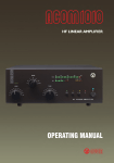
1
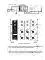
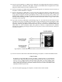
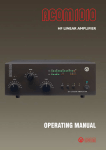
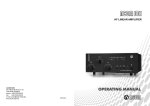
01ÿ34567ÿ839
674
67ÿ147ÿÿ39
1
678
Table of Contents
1. GENERAL INFORMATION ............................................................................... 2
1-1. Introduction and Description....................................................................................... 2
1-2. Owner Assistance ........................................................................................................ 2
1-3. Equipment Supplied and Options ............................................................................... 2
1-4 Features ........................................................................................................................ 3
1-5 Safety Considerations, Explicit Definitions ................................................................... 3
2. INSTALLATION.................................................................................................. 4
2-1. Unpacking and Initial Inspection................................................................................... 4
2-2. Preparing of the system units....................................................................................... 4
2-3. Mounting of the rack option ........................................................................................ 4
2-4. Connections ................................................................................................................ 4
3. OPERATION ....................................................................................................... 7
4. MAINTENANCE ................................................................................................. 7
4-1. Cleaning ..................................................................................................................................... 7
4-2. The ACOM3x2000A Simplified Schematic Diagram.................................................................. 8
4-3. Troubleshooting......................................................................................................................... 8
5. SPECIFICATIONS............................................................................................... 8
6. STORAGE AND SHIPMENT ..................................................................................... 8
1
1. GENERAL INFORMATION
1-1. Introduction and Description
This manual explains the installation, operation and maintenance of the ACOM3x2000A three way, broadband HF
power splitter / combiner.
The ACOM3x2000A is a HF power splitter / combiner which is a passive device designed to sum the outputs of three
HF linear amplifiers into a common load while the amplifiers are driven by a single exciter. For this purpose, the
exciter's (HF transceiver) output power is split in three equal channels, fed to the three amplifier inputs, while the
amplifier outputs are combined and then fed to the common load (antenna). The three splitter output ports as well as
the three combiner input ports are RF-isolated from each other to eliminate the mutual coupling between the three
amplifiers. All ports are designed for 50 Ohm characteristic impedance.
Using three amplifiers permits powering them from a three-phase mains power line. This would distribute the load
among the three power line phases and is preferred to the case with a single-phase power line but loaded three times
greater. An additional benefit with a three-phase power line is considerable reduction of the mains parasitic
modulation of the combined RF signal.
For proper operation, the combiner requires three amplifier outputs having equal amplitudes and phases, i.e. three
coherent signals. This is achieved by the use of three identical amplifiers in the three channels . For best results we
recommend three automatic amplifiers of the type ACOM2000A. Manual tune amplifiers with a precise tuning
indicator like ACOM1200, ACOM1000, ACOM1010 or ACOM1011 can be used too. All these models use a
broadband input network which sets minimum phase differences between the units.
An automatic protection circuit is implemented in the ACOM3x2000A, which monitors the three amplifier outputs
during operation. In case of an imbalance, the protection trips thus cutting the drive to the amplifiers and switching the
transceiver output to an internal 50 Ohm dummy load. The imbalance power, both input and output, is swamped by
powerful resistors until the protection trips. Therefore the transceiver and the three amplifiers are well protected.
After fixing the trouble you can resume operation by pressing the button RESET.
1-2. Owner Assistance
If assistance is needed, you should contact your local dealer first. If you still have an issue, you need to discuss with one
of ACOM's specialists. The contact information is as follows: fax: + 359 2 920 96 56, e-mail [email protected],
or by mail: Blvd. ”Nikola Mushanov”-151, 1330 Sofia, Bulgaria.
1-3. Equipment Supplied and Options
The ACOM3x2000A and accessories are shipped in a single cardboard carton. The package contains:
- ACOM3x2000A splitter / combiner
- 1 pc
- Power supply 12V/0.5A for 100-240V mains voltage
- 1 pc
- 3 m RG58 coaxial cable with PL259 connectors
- 1 pc
- 1.5 m RG58 coaxial cable with PL259 connectors
- 3 pcs
- 1.5 m RG213 coaxial cable with PL259 connectors
- 3 pcs
- 3 m RCA / RCA connectors cable
- 2 pcs (or 1pc paired cable)
- 1.5 m RCA / RCA connectors cable
- 6 pcs (or 3 pcs paired cable)
A metal rack, designed for housing three ACOM2000A amplifiers and the ACOM3x2000A splitter / combiner is
available as separately purchasable option.
1-4. Features
-
Sums three amplifiers outputs;
-
Up to 5000W PEP output power.
2
-
Broadband;
-
Amplifier input ports isolated from each other;
-
Amplifier output ports isolated from each other;
-
Amplifier input ports isolated from output ports;
-
Protection circuit guarantees safe operation of the transceiver and the three amplifiers.
1-5. Safety Considerations, Explicit Definitions
This operating manual contains information, precautions, indications for cautions and warnings which must be followed
by the user to ensure safe operation and to keep the ACOM3x2000A in safe operating condition.
PRECAUTIONS:
The EXPLICIT DEFINITIONS described below apply to this operating manual:
W A R N I N G notes call attention to a procedure which, if not correctly performed, could result in
personal injury, fire hazard or electric shock.
C A U T I O N notes call attention to a procedure which, if not correctly performed, could result in
equipment damage, not only in the amplifier.
N O T E notes call attention to a procedure which, if not correctly performed, could result in
inconvenience.
W A R N I N G HIGH VOLTAGE!
The splitter / combiner works with high RF voltages up to 1000V, which can cause
serious burns! Do not open the device during the operation.
W A R N I N G HIGH VOLTAGE!
Never allow anyone, ESPECIALLY CHILDREN, to push anything into holes in the case this will cause electric shock. NEVER TOUCH AN ANTENNA during transmission - this
may result in an electric shock or burn. NEVER EXPOSE the splitter / combiner to rain,
snow or any liquids. AVOID placing the splitter / combiner in excessively dusty
environments or in direct sunlight. DO NOT OBSTRUCT AIR INTAKE and EXHAUST
(top cover) areas of the splitter / combiner. Keep a minimum distance of 10cm (4
inches) to the intake and 15cm (6 inches) to the exhaust.
WARNING
Do not undertake on your own repairs or changes in the splitter / combiner in order
not to endanger your or other’s health and life and not to damage the device and the
equipment connected with it, not covered by warranty. The manufacturer is not liable
for another’s actions and responsibility shall be assumed by the doer.
CAUTION
To avoid damage (not covered under warranty) read the Installation - Section 2 of this operating
manual carefully. If you have any doubts about the installation, operation or safety of the splitter /
combiner, please consult your dealer.
3
2. INSTALLATION
2-1. Unpacking and Initial Inspection
NOTE
Before you start any action on installing the splitter / combiner, thoroughly read through this
manual. First, carefully inspect the cardboard carton and its content for physical damage. If
damage is noticed, notify your dealer immediately. Delay may infringe carrier's warranty
conditions. Keep all packing for possible future transportation!
2-2. Preparation of the system units
NOTE
The three amplifiers used with the ACOM3x2000A splitter / combiner should all be of same type
and with same settings, which can affect their gain or voltage selector for instance.
The device is designed to be used with three ACOM2000A automatic amplifiers, but it could be used
also with three ACOM1200, ACOM1000, ACOM1010 or ACOM1011 manual tune amplifiers.
NOTE
The transceiver used should produce enough power to drive the three amplifiers, i.e. triple the
drive power required by each amplifier for the needed output. Add some overhead due to the
losses in the system. For instance ACOM2000A requires about 60W drive, therefore the
transceiver should be able to put out 200 W for full output.
2-3. Mounting of the rack option
WARNING
If you use the rack option, be sure to first place an amplifier on the lowest rack level in
the following manner:
Release the two drawer latches on the rear, pull out the drawer, place the amplifier on
it, slide back the drawer and lock the two latches. Afterwards, place the other two
amplifiers in the same way. During an operation, all drawers must be locked and the
wheel brakes engaged.
2-4. Connections
CAUTION
We recommend you use the supplied coaxial cables for the RF connections between the splitter /
combiner and the amplifiers. If you have to use other coaxial cables, please note that the three
coaxial cables going to the amplifier inputs should be the same length, as well as the three coaxial
cables connected to the amplifier outputs. Any difference in lengths would cause a phase
imbalance of the system thus excessive power loss and tripping of the protection circuit.
4
Fig.2-1 Splitter / combiner Connections (only one amplifier is shown. The same connections should be run to the other
two amplifiers)
Fig.2-2 Splitter / combiner Connectors
A) Connect the three supplied 1.5m RG213 coaxial cables with PL-259 plugs from the amplifiers outputs to the
splitter / combiner PA1 OUTPUT, PA2 OUTPUT, and PA3 OUTPUT receptacles.
B) Connect the three supplied 1.5m RG58 coaxial cables with PL-259 plugs from the amplifiers inputs to the
splitter / combiner PA1 INPUT, PA2 INPUT and PA3 INPUT receptacles.
C) Connect the three supplied 1.5 m RCA connector cables from the amplifiers KEY IN sockets to the splitter /
combiner KEY IN 1, KEY IN 2, and KEY IN 3 sockets. If paired RCA cables are supplied use the same color
plugs.
5
D) Connect the three supplied 1.5 m RCA connector cables from the amplifier KEY OUT sockets to the splitter /
combiner KEY OUT 1, KEY OUT 2, KEY OUT 3 sockets. If paired RCA cables are supplied use the other
plugs of the cables already connected to the KEY IN jacks.
E) Connect the supplied 3 m RG58 coaxial cable with a PL-259 plugs from the transceiver antenna connector to
the splitter / combiner RF INPUT receptacle.
F) Connect the supplied 3 m RCA cable, or the the same color plugs of the paired 3 m RCA cable from the
splitter / combiner KEY OUT jack to the transceiver input that disables the transmission while not connected
to the ground. Transceiver producers give different names to this input and they are for instance TXINHIBIT, MUTE, LINEAR, etc. Check your transceiver’s manual. If your transceiver does not have such input,
we recommend connecting this cable in place of transceiver PTT switch as shown on fig. 2-3 and use the
transceiver in PTT mode only.
G) If you have connected the KEY OUT jack according to fig .2-3, then disconnect the PTT switch from the
transceiver and connect it to the KEY IN jack as shown on fig.2-3. Otherwise connect the supplied 3 m RCA
cable from the transceiver socket providing “ground on transmit” to the splitter / combiner KEY IN jack.
Transceiver producers give different names to this output and they are for instance TX-GND, SEND, T/RLINE, AMPL, etc. Some transceivers require that “ground on transmit” is implemented via a software
command, or by changing the setting of a switch on the rear panel, or interior of the transceiver. Check your
transceiver’s manual.
Fig.2-3 Splitter / combiner KEY OUT Connection in series with the transceiver PTT switch
H) Connect the antenna cable with PL-259 PTFE insulated plug to the splitter / combiner RF OUTPUT socket.
CAUTION
Pay attention to the coaxial cable type from the splitter / combiner output. It must handle the
increased power safely, particularly on the higher frequency bands. We recommend you use as a
minimum 7.25 mm (0.285") dielectric diameter PTFE coaxial cable, for instance RG393. Please
note that the popular RG213 of the same size is PE insulated and cannot handle 5000W above
7MHz. Check the same about the antenna selector and tuner as well as the antenna itself
(especially multiband trap antennas).
I)
Insert the 12V power supply plug into the splitter / combiner socket marked 12V DC.
6
3. OPERATION
CAUTION
Before you turn the splitter / combiner on, at least 2 hours should have expired since it was
brought in and unpacked in the room where it will be used. Pay particular attention when you
move it from a very cold into a very warm place - condensation is likely and this could result in
damage to the high voltage circuits. In such a case, wait at least 4 hours. A similar effect can occur
after a rapid warming of the operating room (for instance after switching on a powerful heater).
After following all instructions in S.2, you can plug the supplied 12V wallwart power supply into the mains outlet. The
green LED on the front panel must light, showing that the device is turned ON and READY.
Turn the amplifiers ON and in OPERATE mode.
After having put together the system and before use, you should prepare user tunings on each ACOM2000A amplifier
separately for the bands, segments, and antennas, which will be used. These tunings will be automatically and
simultaneously retrieved from each ACOM2000A memory later when you change the operation frequency or
antennas.
The user tuning should be done in the following way (see also ACOM2000A Operating manual, S. 4-2):
-
The three amplifiers should be turned on the same frequency segment and in OPERATE mode;
-
Press the TUNE button on the first amplifier’s RCU;
-
Apply between 10 and 20 W continuous (CW) drive from the transceiver;
-
The tuning will be completed in few seconds and simultaneously the splitter / combiner protection will trip;
-
Remove the drive power and press RESET button on the splitter / combiner front panel;
-
Repeat the same steps successively on the second and the third amplifier;
The same procedure should be applied on every frequency segment / antenna combination, which will be used.
In case of manual tune amplifiers, each of them should be re-tuned precisely each time you change a band and/or
antenna.
Now you can start operating in the same manner as if you are operating a single amplifier.
Should the protection circuit trip most likely the amplitude or phase difference between the outputs of any two
amplifiers is too high. One of the red LEDs will light, identifying the amplifier, which most likely produced the
imbalance. Stop the transmission, check the status of the amplifier identified, its connections, and then the settings and
tunings of all amplifiers. If everything is in order but the problem persists, reduce the drive power and check the
transceiver for leading RF spikes. Apply constant ALC biasing to the transceiver ALC input in case of spikes. Finally
press the RESET button to resume the operation.
4. MAINTENANCE
4-1. Cleaning
WARNING
Do not use solvents for cleaning - they may be dangerous both for you and for the
splitter / combiner paint.
Do not open the splitter / combiner. Cleaning can be done with a piece of soft cotton cloth lightly moistened with
clean water.
7
4-2. The ACOM3x2000A Simplified Schematic Diagram
4-3. Troubleshooting
In a case of a problem, contact the service department of your dealer (see S.1-2).
5. SPECIFICATIONS
a) Frequency Coverage: 1.8-30 MHz continuous
b) Power Output: 5000W PEP or continuous carrier into a matched load (VSWR below 1.3:1). Reduce the output at
increased VSWR, linearly down to 2500W at VSWR up to 2:1.
c) Input and Output Impedances:
- nominal value: 50 Ohm unbalanced, UHF (SO239) type connectors;
- input circuit: broadband;
- input VSWR with 50 Ohm loads at the three splitter outputs: less than 1.3:1, 1.8-30MHz continuously (no tunings, no
switching);
maximum output mismatch: up to 2:1 at reduced output - see (b) above.
d) Primary Power: 100-240V via a 12V wallwart adapter (supplied).
e) Size & Weight (operating): W210mm x D325mm x H195mm, 6.4 kg.
f) Operating environments:
- temperature range: 0...+50 degs.Celsius;
- humidity: up to 95% @ +35 degs.Celsius.
6. STORAGE AND SHIPMENT
CAUTION
a) Storage environments: the splitter / combiner can be kept packed in dry and ventilated unheated premises without
chemically active substances (acids, alkalis etc.) in the following climatic environment:
-
temperature range: -40 to +70 degs.Celsius;
-
humidity: up to 75% @ +35 degs.Celsius.
b) Shipping Size and Weight:
W390mm x D330mm x H350mm, 9.4 kg
c) Shipping environments: all types of transportation, including aircraft baggage section.
8