1
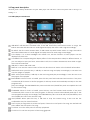
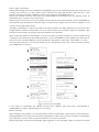
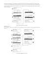
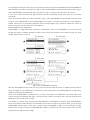
USER MANUAL---------------------------------------------------------------------------------1-26
Table of Contents
1 Product description ……………………………………………………………………………………………..1
2 Safety instructions ……………………………………………………………………………………………….2
3
Connections and control elements ………………………………………………………………………….3
3.1 Rear panel description ………………………………………………………………………………………3
3.2 Front panel description ………………………………………………………………………………………3
3.3 Top panel description ………………………………………………………………………………………...4
3.3.1 MP3 player control area ……………………………………………………………………………………4
3.3.2 MP3 player function description ………………………………………………………………………….5
3.3.3 Mixer function area …...…………………………………………………………………………………….9
3.3.4 Mixer control area…………………………………………………………………………………………..10
4
Configuration …………………………………………………………………………………………………….12
4.1 Connection …………………………………………………………………………………………………….12
4.2 Operation precaution ………………………………………………………………………………………..12
5
1
Technical specifications ……………………………………………………………………………………….13
PRODUCT DESCRIPTION
1 2 channel stereo DJ mixer with built-in MP3 decoder.
2 Multiple input and output: input included 1 Mic input, 1 USB input, 1 SD card input, 2 CD input, 2
line input, 2 PHONO input with RIAA trait; output included 1 master output, 2 REC output and 1
headphone output.
3 Blue backlight LCD DOT matrix display with contrast control.
4 Compatible with 4GB SD card and USB stick, full navigation of MP3 with EZ search encoder.
5 Mic input channel with Level and Tone adjust; 2 stereo input with individual Gain, 3 band EQ
(HIGH, MID, BASS) and Vol adjust.
6 200 000 cycles Crossfader & Headphone Crossfader.
7 Stereo headphone monitoring output with MIX, CUE MIX and CUE LEVEL.
8 Input and output channel with individual LED level indication.
9 External low power adapter, which make the unit more safety and better Signal-to-Noise.
10 High glossy finish which make the unit more beautiful.
11 High quality components and our good workmanship, which make our products more reliable.
1
2 SAFETY INSTRUCTIONS
The lightning flash with arrowhead symbol inside an equilateral triangle is intended to alert User
that the presence of uninsulated "hazardous voltage"within the product’s enclosure, which
may be of sufficient magnitude to induce a risk of electric shock to persons.
The exclamation mark inside an equilateral triangle is intended to alert user that the presence
of important operating and maintenance (servicing) instructions in the literature accompanying
the product.
The apparatus shall not be exposed to dripping or splashing and that no objects filled with liquids,
such as vases, shall be placed on the apparatus.
WARNING: TO REDUCE THE RISK OF FIRE OR ELECTRIC SHOCK, DO NOT EXPOSE THIS APPLIANCE TO
RAIN OR MOISTURE.
1. Caution: To reduce the risk of electric shock, do not remove
cover(or back). No user-serviceable parts inside. Refer servicing to
qualified personnel.
2. Do not install the equipment in a place exposed to direct sunlight.
3. Do not install the equipment in a dusty, damp or poorly ventilated
place.
4. To prevent damage to the equipment, please unplug from the
power outlet if not in use.
5. To unplug the equipment, always handle the power cord using the
plug. Do not pull out the plug by tugging the cord.
6. Place the equipment on a stable surface and avoid placing other
objects on top.
7. Cleaning care: Use a soft, dry cloth for cleaning. For stubborn dirt,
soak the cloth in a weak detergent solution; wring well and wipe to
remove the dirt. Do not use volatile agents such as benzene or paint
thinner, as they may damage the surface finish of the equipment.
8. Please do not block the cooling vents to avoid overheating.
9. No naked flame sources, such as lighted candles, should be placed
on the apparatus.
2
3 CONNECTIONS AND CONTROL ELEMENTS
3.1
Rear panel description
Power input, signal input and output components are placed in the rear panel, please refer to Fig
3.1.0:
Fig 3.1.0 rear panel layout
INPUT CH1: When use the same RCA input jacks for PHONO input and Line input, slide to upper
for PHONO input, and slide adown for Line input.
INPUT CH1PH1/L1: PHONO and LINE are the same input jacks; you can choose each of them as
per your requirement, this selection is controlled by Switch
.
Attention: Due to the big difference of input sensitivity between PHONO and LINE, please slide
the switch to the position you need firstly, and preset the volume of the related components on
the top panel, and then connect the signal.
INPUT CH1 CD1: for connecting the output signal of CD player.
INPUT CH1 GND: for connecting the external signal source, so as to avoid interference and
improve the Signal-to-Noise.
INPUT CH2: the same working principle as INPUT CH1.
INPUT CH2 PH2/L2: the same working principle as INPUT CH1PH1/L1.
INPUT CH2 CD2: the same working principle as INPUT CH1 CD1
INPUT CH2 GND: the same working principle as INPUT CH1 GND.
OUTPUT MASTER OUTPUT: for connecting the external power amplifier or other audio processors.
OUTPUT REC OUTPUT: Here the output signal is not controlled by the Master volume; it is for
external REC devices.
Power input jack: for connecting the AC power adapter to the mixer, you may use AC 12V,
50Hz or 60Hz output adapter as the power of this unit.
Power ON/OFF: to connect or disconnect the power supply.
3.2 Top panel layout
Mic input jack and headphones output jack are placed on the top panel; please refer to the Fig
3.2.0.
Fig 3.2.0 front panel layout
MIC INPUT:6.35mm BALANCED and UNBALANCED input,which is suitable for MIC which
impedance is around 600 ohm。
HEADPHONES:6.35mm stereo output, which is suitable for headphone which is 32~64 ohm。
3
3.3 Top panel description
The front panel is mainly divided into two parts: MP3 player area and mixer control area please refer to the Fig 3.3.0
and Fig 3.3.1.
3.3.1 MP3 player control area
Fig 3.3.0 front panel layout (MP3player area)
USB INPUT: USB device is inserted here, if the USB stored any MP3 format music or songs, the
built-in decoder will decode out audio signal and play the music and songs accordingly.
SD INPUT: the SD card is inserted here, if USB stored any MP3 format music or songs, the built-in
decoder will decode out audio signal and play the music and songs accordingly.
LCD display: it is a blue backlight dot matrix LCD, all the functions of MP3 player can be
displayed via this LCD.
CONTRAST: for compensating the display effect for the temperature variety in different areas, or
you can adjust as per your favor, when slide to left, the contrast decreased, when slide to right,
the contrast increased.
USB/SD: To select USB or SD card.
DISPLAY: can see the current status of the LCD, like the PLAY status or the PLAYLIST information.
PREVIOUS: when press this key, it will skip to the last song and play accordingly. It can also turn
over the pages of playlist.
NEXT: when press this key, it will skip to the next song and play accordingly. It can also turn over
the pages of the playlist.
BACKWARD: when in PLAY or PAUSE, press this key can fast backward and monitor. If we press
continuously till it comes to the first program, it will stop search automatically and skip to the last
program and
play accordingly. This BACKWARD key can work with PLAY/PAUSE key and accomplish the CUE
for the current song.
FORWARD: When in PLAY or PAUSE, press this key can fast forward and monitor. If we press
continuously till it comes to the next program, it will stop search automatically and skip to the
next program and play accordingly. This FORWARD key also can work with PLAY/PAUSE key and
accomplish the CUE for the current song.
PLAY/PAUSE: When press this key, it will start or stop the current song, it also can be the
confirmation key for other functions.
CUE: to play a song which is set the CUE point, if there is no CUE point of a song, the default CUE
point will be the start point of a song.
LOOP-IN: to set the start point of the loop playback.
LOOP-OUT: to set the end point of the loop playback.
4
RELOOP: press this key to start or to stop the looping section which is playing.
MENU/NO: press this key to show the main MENU of this unit, and also can check the current
play status or playlist information as well as the enquiry function of other keys.
PLAYLIST: with PUSH/ENTER, PREVIOUS, NEXT, PLAY/PAUSE and MENU/NO can set up the list,
playback and delete of the Mp3 songs.
PUSH/ENTER: this is a push switch with a rotary encoder, with this rotary function, we can select
the menu up and down, when press this button, we can confirm the selection we made, when
works with other keys, we may accomplish all kinds of desired functions.
3.3.2
MP3 player function area
1 The loading and playback of MP3
After connecting power supply, Fig 3.3.2-1 A will appear in the LCD, if there is no USB and SD card
inserted, the Fig A will be changed to Fig B. If there is no contents or no any MP3 format inside the
USB and SD card, Fig B will be NO MP3 MUSIC!
So if we insert USB or SD card with MP3 format, the Fig B will be change to Fig C, it means the songs of
the USB are being loading, the LCD also displays the amount of the songs.
If we insert the USB or SD card firstly and connect to power after, the LCD will displays the Fig A and
then change to Fig D, the loading sequence of the system will be SD card first and then USB stick.
After loading, all the songs as well as the titles and numbers will be displayed according to the
playlist like the Fig E as show below. There are only 4 songs displayed in each page of the LCD, for
more information, please use PUSH/ENTER, PREVIOUS or NEXT to change the pages, the system can
load 500 MP3 songs maximum, due to the there is no more storage inside the system, the loading
capacity is depending on the volume of the USB stick or SD card.
You can use PUSH/ENTER, PREVIOUS or NEXT to select the songs in the playlist, like the second song in
Fig E, an then press PLAY/PAUSE to play directly.
When playing, the first row shows the current device, total songs and the current song; the second
row shows the current title of a song; the third row shows the playback process via graphics mode.
The fourth row shows the current playback time, and after it will be remain time of palyback.
Fig 3.3.2-1 Loading and direct playback
2 CREATE PLAYLIST
If you want to reorganize the playback list and sequence of the songs, please enter the edit status
and set up the playlist. You can set up 10 playlist, in each playlist, you can put 120 songs, please
5
refer to fig 3.3.2-2 below:
After finish loading, press PLAY/PAUSE or PUSH/ENTER to go into the playback, like Fig A, and also you
can go into pause as you wish. When press PLAYLIST, the Fig B will appear, from the top to the
bottom, there are 3 playlist: CREATE PLAYLIST, PLAY PLAYLIST and ERASE PLAYLIST.
Select the CREATE PLAYLIST, and press the PAUSE/TNTER or PLAY/PAUSE key, the display shows 10
playlist like fig C and all of them are empty.
Select each of them and set up your playlist, like the first list PLAYLIST 01 [EMPTY], press PUSH/ENTER or
PLAY/PAUSE, Fig D will appear, and then Fig E, on the left top of Fig E, there is a clue on playlist 1, you
can put your songs inside the list.
Use NEXT or PREVIOUS to select the songs, then press PLAYLIST, the Fig F will appear, it means the first
song has been added to the playlist, so use the same method to put other songs to the playlist 1, like
the Fig G which means 52 songs have been added to the playlist1.
When songs are added to the playlist, you can store them. just press PLAYLIST for 3 seconds till the Fig
H appear, and select SAVE & CLOSE PLAYLIST 01, press PUSH/ENTER or PLAY/PAUSE, Fig I will appear,
then press YES, and PUSH/ENTER or PLAY/PAUSE, fig J will appear, then Fig K. then playlist 1 is done.
Use the same methods to set up the playlist 2 to 10, during the set up, if you want to cancel, please
press MENU/NO to cancel.
Fig 3.3.2-2 set up the playlist
If you want to exchange the SD/USB, please press USB/SD, and then press PLAY/PAUSE or
PUSH/ENTER to confirm. After loading, it is ok to play.
3 PLAY PLAYLIST
After setting up the playlist, you can play each of them, please refer to the Fig 3.3.2-3 for operation.
During playback of a song, press PLAYLIST, Fig B appears, select the PLAY LIST and press PLAY/PAUSE,
Fig C appears, and you may found the PLAYLIST is not empty anymore.
Select PLAYLIST01, and press PLAY/PAUSE, Fig D appears, on the top right of fig D, it shows the current
6
songs are from playlist 1, meanwhile, it shows the amount of the songs as well as the current songs.
If you want to exit the playlist, press PLAYLIST key, and the STOP PLAYLIST in Fig E, then PUSH/ENTER or
PLAY/PAUSE key, press YES to come back to the original Stochastic playback mode in Fig F, please
refer to the Fig G.
Fig 3.3.2-3 playback of playlist
4 ERASE PLAYLIST
If you want to cancel the playlist you set up before, you may erase it as per the fig 3.3.2-4 show
below:
Fig3.3.2-4 EARSE the PLAYLIST
7
If the playlist existed, but the status is stochastic, please press PLAYLIST-ERASE PLAYLIST-PUSH/ENTER or
PLAY/PAUSE, and select PLAYLIST01 in Fig G, then PUSH/ENTER or PLAY/PAUSE, select YES in Fig H,
then PUSH/ENTER or PLAY/PAUSE, after fig I, there is Fig J, it means one PLAYLIST 01 is erased.
If you are in PLAY PLAYLIST, like Fig B, please exit the PLAYBACK mode and then do your erase
operation.
Press the PLAYLIST, select the STOP PLAYLIST in Fig C, press PUSH/ENTR or PLAY/PAUSE, then press YES
in Fig D, and PUSH/ENTER or PLAY/PAUSE again, then Fig E, it means the playback of the playlist is
exited, and now is in stochastic playback. Press PLAYLIST again, Fig F appears, follow the same as
below can carry out the erase of the playback.
5 PUSH/ENTER quick application
PUSH/ENTER is a high efficiency operation components, with this PUSH/ENTER; we may read and
locate the Menu or playlist quickly and also may check the details for the current songs, for more
details, please refer to 3.3.2-5.
Fig 3.3.2-5 PUSH/ENTER operation
With the PUSH/ENTER rotary knob, we may fast read and locate the menu or playlist, please refer to
Fig A and Fig B, if you would like to continue the next step, please use PUSH/ENTER for confirmation,
otherwise please press MENU/NO.
When uses PUSH/ENTER in a playback of a song, it will select the playlist first and then select the
current song automatically, like Fig C. and if you don’t want to continue the next step, please press
MENU/NO to exit and back to Fig D.
For details of current song, except press BACKWARD or FORWARD for search, press PUSH/ENTER is
much convenient. Take the Fig F for example; if you want to search one point to play, you may press
PUSH/ENTER, please refer to the Fig G. when rotary PUSH/ENTER to right, the icon will go to right,
please refer to Fig H, when press PUSH/ENTER, it will be confirmed to the new position and start the
playback here, please refer to Fig I.
8
6 CUE set up and two basis operation:
CUE set up: use BACKWARD key or FORWARD key together with PLAY/PAUSE to finish the setup,
when one song is in playing mode, press PLAY/PAUSE key to pause, and then press BACKWARD or
FORWARD key to set up the CUE point. After finishing set up, press PLAY/PAUSE key, the song will
continue to play, and the CUE key LED will be illuminated.
During the playback of one song, you can set up several CUE points, but only the last one is valid.
Basic operation 1: if there is no CUE point in the playback of a song, no matter where is song is, press
CUE key, the song will come back to the start point and will be in pause mode, if we hold the CUE
key, it will come back to the start point as well and continue to play. When release the CUE key, it
will come back to the start point of the song and will be in Pause mode, during all this operation, the
red LED of CUE will not illuminated.
Basic operation 2: after setting the CUE point of a current song, press CUE key will make the song
come back to the cue point and in pause mode. If we hold his key, the song will also back to the
cue point and continue to play, when release the CUE key, the song will come back to the cue
point and in pause mode. During all these operation, the red LED of CUE will be illuminated.
CUE is only valid to the same song.
7 Loop function:
Set up the Loop In: press Loop-In during the playback or Pause of one song, the blue LED inside will
be illuminated, the start point of Loop is set up.
Set up the Loop Out: once set up the start point of Loop, then press Loop Out to set up the end point,
the blue LED inside the Loop Out will be illuminated, then the Loop section is finished, the song will
come back to the start point and play automatically.
If you did not cancel the Loop function, once the playback of the loop section is finished, the song
will come back to the start point and continue to play the loop section, if you want to cancel the
Loop, please press the Loop-out key or RELOOP key to cancel the loop, and the blue LED will be go
out. The Loop playback will be valid to the same song only.
3.3.3 Mixer function area
Including Line input CH1, line input CH2, Mic input, master channel and Level indication, please refer
to the fig below:
Fig 3.3.1 front panel layout(Mixer control area)
MIC LEVEL: control the volume of MIC, when slide to the right side, the volume is increased,
when sided to the left side, the volume is decreased or closed.
9
MIC TONE: control the tone of Mic, when slide to the right side, the HIGH is increased and BASS is
attenuated; when slide to the left side, the BASS is increased and the HIGH is attenuated. When
slide to the 0 position, the Tone will not be increased or decreased.
CHANNEL 1 INPUT SELECT: select one signal from CD1 or USB/SD or PHONO1/LINE 1, and then
send to CH1 for processing.
CHANNEL 1 GAIN: control the gain of input channel1, when slide to the left side, the gain is
decreased, when slide to the right side, the gain is increased.
CHANNEL 1 HIGH: for the control of the 10KHz of input channel, when slide to left, the HIGH is
attenuated, the max attenuation is 26dB, when slide to right, the HIGH is increased, the max
increasing is 12dB. When slide to the 0 position, the HIGH will not be increased or attenuated.
CHANNEL 1 MID: for the control of the 1.1KHz of input channel 1, when slide to left, the MID is
attenuated, the max attenuation is 26dB; when slide to right, the MID is increased, the max
increasing is 12dB, when slide to 0 position, the MID will not increase or attenuate.
CHANNEL 1 BASS: for the control of the 75Hz of input channel 1, when slide to left, the BASS is
attenuated, the max attenuation is 26dB; When slide to right, the BASS is increased, the max
increasing is 12dB, when slide to 0 position, the BASS will not increase or attenuate.
CHANNEL 1 VOLUME: for the Volume control of input channel1, when slide the fader adown,
the volume is decreased; then slide the fader upwards, the volume is increased.
CHANNEL 2 INPUT SELECT: Select one signal from CD2 or USB/SD or PHONO2/LINE 2, and then
send to CH2 for processing.
CHANNEL 2 GAIN: same as channel1
CHANNEL 2 HIGH: same as channel1
CHANNEL 2 MID: same as channel1
CHANNEL 2 BASS: same as channel1
CHANNEL 2 VOLUME: same as channel1
CROSSFADER: control the proportion of the signal between input channel1 and input channel 2
MASTER VOLUME: control the Master volume of this mixer, when slide to left, the volume is
decreased; when slide to right, the master volume is increased.
CHANNEL 1 LEVEL DISPLAY: 3 LED are used for indicating the level of input channel 1 timely.
green LED is the indication of the minimum input signal(≤-40dB, the yellow LED is the indication
of rated input signal, the red Led is the indication of 2 times rated input signal.
CHANNEL 2 LEVEL DISPLAY: 3 LED are used for indicating the level of input channel2 timely. The
indication principle is the same as input channel1.
MASTER LEVEL DISPLAY: 3 LED are used for indicating the level of master channel timely. The
green LED is the indication of the minimum output signal (≤-35Db), the yellow LED is the
indication of 0dB output signal (≥0dB), the red LED is the indication of rated output signal
(≥+4dB).
CUE MIX: control the proportion of the signal between input channel1 and input channel 2
PHONES LEVEL: to control the monitoring Volume, when slide to left, the volume is decreased,
when slide to right, the volume is increased.
3.3.4 Mixer control area
1 3 basic applications of crossfader
When slide the fader to the middle position, the signal of input channel 1 and input channel 2 is sent
to the main channel for processing. The output signal is the mixed signal of the two channels.
When slide to left, the corresponding signal of input channel 2 is attenuated, when slide to right, the
corresponding signal of input channel1 is attenuated.
10
When slide to the end of the left side, it keeps only the signal of input channel1 and shut the signal of
input channel2; when slide to the end of right side, it keeps only the input channel two and shut the
signal of input channel1.
2 3 basic applications of monitoring control
When the fader is in the middle position, it can monitor the signal of input channel1 and input
channel2.
When the fader is slid to left, it correspondingly increases the signal of input channel1 and
attenuates the signal of input channel2.wherease it correspondingly increases the signal of input
channel2 and attenuates the signal of input channel1.
When slide the fader to the left end, it monitors the signal of input channel1 and shuts the signal of
input channel2, whereas it monitors the signal of input channel2 and shuts the signal of input
channel1.
The monitoring channel is designed behind the 3 band EQ, and before the Volume control, so the
monitoring channel relatively has 3 band EQ, and will be controlled by the gain control of input
channel.
3 The Level indication sensitivity of input channel and master channel is in terms of stereo input and
output, you may observe the level indication of each channel and make the signal assignment to
the complete system timely, in order to make them work in the best status.
11
4 CONFIGURATIONS
4.1 System connection
We may connect 2 PCS CD player (or 2 PCS PHOHO), 2 Line, 1MIC, 1USB and 1SD and output 1
headphone, 1 stereo power amplifier,1 REC device at the same time, Due to the low output
impedance of the master channel, so it has big loading capability, you may connect many output
devices via proper combination, please refer to the connection below:
Fig 4.0.2 input connection of rear panel
Fig 4.0.1 input and output connection
of front panel
Fig 4.0.3 output connection of real panel
4.2 OPERATION PRECAUTIONS
Please read the points below carefully. For more details, please read the details in chapter 3.
4.2.1
In order to make sure the system connection is proper; please connect according to
chapter 4.
4.2.2
Each time before connecting to power supply, we suggest turning the gain and volume to
minimum position; at least the master volume should be turned to minimum position in
order to avoid the impact to the output device when starting the unit.
4.2.3
Please turn on the power sources in sequence, primary equipments first. When turn off the
system, please operate in opposite sequence, it is important to your system.
12
5 Technical specifications
Rated Inputs
Microphone……………………………………………………… -45dB 1k/2k ohm Unbalanced/Balance
Phono ……………………………………………………………………………………. -50dB 50k ohm Stereo
CD …………………………………………………………………………………………. -6dB 15k ohm Stereo
USB……………………………………………………………………………………..…. -14dB 15k ohm Stereo
Rated Outputs
Master Output ………………………………………………………………………..….. +4dB 50 ohm Stereo
REC Output …………………………………………………………………………………. 0dB 1k ohm Stereo
Phones …………………………………………………………………………….. 300mW 32~64 ohm Stereo
Distortion ……………………………………………………………………………………………………… ≤ 0.1%
S/N Ratio ……………………………………………………………………………………………………… ≥ 75dB
Separability ………………………………………………………………………………………………..… ≥ 50dB
Frequency Response
Microphone ……………………………………………………………………………… 50Hz~18kHz +1/-2dB
Master …………………………………………………………………………………... 20Hz~20kHz +1/-2dB
REC ………………………………………………………………………………………… 20Hz~20kHz +1/-2dB
Phones ………………………………………………………………………………...… 20Hz~18kHz +1/-2dB
Equalizer
High ……………………………………………………………………………. +12dB/-26dB Channel 1 and 2
Mid …………………………………………………………………………….. +12dB/-26dB Channel 1 and 2
Bass ………………………………………………………………………….… +12dB/-26dB Channel 1 and 2
Tone……………………………………………………………………... +12dB/-12dB Microphone Channel
Adapted Power Source ……………………………………………………………………... AC 12V 50/60Hz
Max Power Consumption ………………………………………………………………………………….… 28W
Unit Dimensions ……………………………………………………………...… W210mm×H100mm×D356mm
Weight …………………………………………………………………………….……… 4.1 kg (Include Power)
All features and specifications are subject to change without notice.
Disposal of Old Electrical & Electronic Equipment (Applicable in the European Union and other
European countries with separate collection systems).
This symbol on the product or on its packaging indicates that this product shall not be treated as
household waste. Instead it shall be handed over to the applicable collection point for the recycling
of electrical and electronic equipment. By ensuring this product is disposed of correctly, you will help
prevent potential negative consequences for the environment and human health, which could
otherwise be caused by inappropriate waste handling of this product. The recycling of materials will
help to conserve natural resources. For more detailed information about recycling of this product,
please contact your local Civic Office, your household waste disposal service or the shop where you
purchased the product.
13
Table des matières
1 Description du produit…………………………………………………………………................................14
2
Sécurité …………………………………………………………………………………..................................15
3
Connections et boutons de contrôle ………………………………………………................................16
3.1 Description du panneau arrière…………………………………………………...................................16
3.2 Description du panneau avant…………………………………………………....................................16
3.3 Description du panneau de dessus…………………………………………….....................................17
3.3.1 contrôle des mp3 …………………………………………………........................................................17
3.3.2 Fonction du lecteur MP3 ………………………………………...........................................................18
3.3.3 La partie mixage …...…………………………………..…………….......…..........................................23
3.3.4 Contrôle du mixage…………………………………………………....……..........................................24
4
Configuration ………………………………………………………….………….……………………………..25
4.1 Connection ……………………………..…………………………………………………………………….25
4.2 Précautions d’utilisation……………………………..………………………………………………………25
5 Spécifications techniques ……………………………………...…………………………………………….26
1 DESCRIPTION DU PRODUIT
1 2cannaux stereos DJ Mix avec encodeur MP3 intégré.
2
Plusieurs entrées et sorties:
- les entrées il y a 1 entrée microphone, 1 port USB, 1 slot pour carte SD, 2 entrées CD, 2 entrées Line-in (line
input),2 entrées PHONO (PHONO), entrée RIAA;
- les sorties : output included 1 master output, 2 sorties REC(enregistrement) et 1 sortie écouteurs.
3 Ecran LCD retro-éclairé avec reglage du contraste.
4 Compatible avec des cartes SD 4Go et clé USB, navigation et recherché MP3.
5
Entrée Microphone avec control du volume (Level) et du Tone; 2 entrées stéréos avec un contrôle du gain par entrée,
un équalizer 3 bandes (HIGH, MID,BASS) et contrôle du volume.
6
Crossfader concus pour 200.000 cycles.
7 Monitoring avec MIX, CUE MIX et CUE LEVEL.
8 Indicateur LED pour chaque sortie.
9 Adaptateur externe bas voltage pour reduire les effets de bruit.
10 Finition laqué.
11 High quality components and our good workmanship, which make our products more reliable.
14
2 PRECAUTIONS D’UTILISATION
Le symbole avec la flêche en forme d’éclair signifie qu’un courant assez fort pour
induire un risque d’éléctrocution circule à l’intérieur du boîtier.
Le point d’exclamation à l’intérieur d’un triangle equilateral est là pour rappeler à
l’utilisateur que la machine est fragile, et qu’elle à besoin d’un entretiens régulier
(voir les instructions qui accompagne le produit).
L’appareil ne doit pas êre exposé à de l’humidité ou place prêt d’objets remplis de liquides (vases,
bouteilles d’eau).
WARNING: POUR REDUIRE LES RISQUES D’INCENDIES OU DE CHOCS ELECTRIQUES, N’EXPOSER PAS CE
PRODUIT 0 LA PLUIE OU AUX MOISISSURES.
1. Attention: Pour réduire les risques de choc électriques, ne retirez
pas le couvert. Contyacter notre hotline pour tout problem rencontre.
2. N’installez pas l’unité à un endroit exposé aux rayons du soleil.
3. N’installez pas l’unité dans un endroit poussiéreux, humide ou peu
ventilé.
4. Pour protéger votre équipement débranchez le lorsque vous ne
l’utilisez pas.
5. Pour débrancher l’unité, veuillez toujours tirer sur la prise elle-même
et non sur le câble d’alimentation.
6. Placer l’équipement sur une surface stable et évitez de placer
d’autres objets dessus.
7. Entretient: Utilisez un tissues doux et sec pour le nettoyage.
Pour les taches plus tenaces, utilisez un détergent peu aggressif; et
essuyez en appuyant bien pour enlever la saleté. N’utilisez pas
d’agents volatiles tels que le benzene ou le diluant à peinture, car ils
peuvent endommager la finition du boîtier.
8. Veuillez ne pas bloquer les aerations pour éviter les surchauffes.
9. L’unité ne devra pas être place prêt de flammes nues comme les
bougie par exemples.
15
3 CONNECTIONS AND CONTROL ELEMENTS
3.1 Descriptif du panneau arrière
Power input, signal input and output components are placed in the rear panel, please refer to Fig
3.1.0:
Fig 3.1.0 rear panel layout
ENTREE CH1: Lorsque vous utilisez le meme cable RCA pour l’entrée PHONO input et Line-in,
utilisez le switch pour sélectionner l’entrée PHONO input ou Line-in.
ENTREE CH1PH1/L1: PHONO et LINE-IN sont sur une seule sortie. Vous pouvez opérer un selection
grace au bouton.
Attention: En raison d’une grande difference de sensibilité entre l’entrée PHONO et LINE-IN, veuillez
d’abord sélectionner la position appropriées, et régler le volume des éléments connectés sur le
panneaux principal et ensuite allumer l’unité.
ENTREE CH1 CD1: Pour brancher un lecteur CD.
ENTREE CH1 GND: Pour brancher une source extèrieur, pour éviter les interferences et pour un
meilleur ratio S/N.
ENTREE CH2: Fonctionne sur le même principe que pour l’entrée CH1.
ENTREE CH2 PH2/L2: Fonctionne sur le même principe que pour l’entrée INPUT CH1PH1/L1.
ENTREE CH2 CD2: Fonctionne sur le même principe que pour l’entrée INPUT CH1 CD1
ENTREE CH2 GND: Fonctionne sur le même principe que pour l’entrée INPUT CH1 GND.
SORTIE MASTER: Connectez un amplificateur ou des enceintes.
SORTIE REC: COnnectez un peripherique d’enregistrement.
Alimentation: pour brancher l’adaptateur AC à la table de mixage, vous pouvez utiliser un
adaptateur AC 12V, 50HZ ou 60HZ pour alimenter l’unité.
Power ON/OFF: to connect or disconnect the power supply.
3.2 Panneau avant
Les entrées Micro et Ecouteurs sont placées sur le dessus; veuillez vous référer à la figure 3.2.0.
Fig 3.2.0 Panneau avant
ENTRÉE MICRO: Entrée 6.35mm, convenable pour micro avec une impedance de 600 ohm。
ECOUTEURS: Sortie 6.35mm stereo, convenable pour des ecouteurs de 32~64 ohm。
16
3.3 Le panneau principal
Le panneau du dessus est principalement divisé en deux parties: une partie pour le contrôle des
MP3 et une autre pour le contrôle du Mix; veuillez vous reférer aux figures 3.3.0 and Fig 3.3.1.
3.3.1 Zone de controle MP3
Fig 3.3.0 Panneau principal (zone MP3)
LE PORT USB: les sources audio USB y sont insérées. Si elles contiennent des fichiers MP3, le
décodeur integré détectera un signal audio et lira le son automatiquement.
LE SLOT SD: la carte SD y est insérée. Si elle contient des fichiers MP3, le décodeur integré
détectera un signal audio et lira le son automatiquement.
L’ECRAN LCD: C’est un ecran LCD avec un retro-éclairage bleu, toutes les fonctions du lecteurs
MP3 sont lisibles sur cette écran.
CONTRASTE: permet de regler le contraste de l’affichage LCD.
USB/SD: Pour sélectionner le port SD ou USB.
DISPLAY: affiche les MP3 en cours de lecture ou la liste de lecture sur le LCD,.
PREVIOUS: Sert à passer à la chanson ou à la liste de lecture précédente.
NEXT: Sert à passer à la chanson ou à la liste de lecture suivante.
BACKWARD: En lecture ou en pause, appuyez sur cette touche pour effectuer un retour rapide.
FORWARD: En lecture ou en pause, appuyez sur cette touché pour effectuer une avance
rapide.
PLAY/PAUSE: Ce bouton permet de lancer ou d’arréter la lecture, elle sert aussi de touche de
confirmation pour d’autre fonctions.
CUE: permet de commencer la lecture au point CUE, s’il n’y a pas de point CUE la lecture
commencera au debut du fichier.
LOOP-IN: sert à definir le point de depart d’une boucle (loop).
LOOP-OUT: sert à definir la fin d’une boucle.
RELOOP: Sert à lancer ou à arréter la lecture d’une boucle.
MENU/NO: ce bouton sert à afficher le menu principal de l’unité, et sert aussi à afficher la
chanson ou la liste de lecture en cours.
PLAYLIST: Avec les touches PUSH/ENTER、PREVIOUS、NEXT、PLAY/PAUSE et MENU/NO vous pouvez
definer une liste de lecture, lancer la lecture ou la suppression de fichiers MP3.
PUSH/ENTER: vous pouvez naviguer dans le menu de haut en bas, et en appuyant vous pouvez
confirmer votre sélection, en l’utilisant avec d’autres boutons vous pouvez aussi utiliser d’autres
fonctions.
17
3.3.2
MP3 player function area
1 Le chargement et la lecture des MP3
Après avoir branché le cable d’alimentation, l’ecran montré sur la Figure 3.3.2-1 s’affichera sur le
LCD. Si il n’y a pas de clés USB ou de carte SD insérée l’écran affichera le message montré dans la
figure B. Si il n’y a aucun fichiers MP3 sur la clé USB ou sur la carte SD l’écran de la figure B affichera
NO MP3 MUSIC !
Si vous avez inséré une clé USB ou une carte SD contenant des MP3, l’écran s’affichera comme sur
al figure C, qui indique que les cahsons sont en cour de chargement, l’écran indique aussi le
nombre de chanson.
Si vous connectez un peripherique USB ou une carte SD puis mettez sous tension le NMX4000 l’ecran
affichera la Fig.A puis changera en Fig. D, la sequence de chargement commence par la carte SD
puis USB.
Après le chargements toutes les chansons incluant leurs titres et leurs nombres s’afficheront comme
indiqué sur la figure E. L’écran n’affichera que 4 chansons par page à la fois, pour plus
d’information, veuillez apuyer sur le bouton PUSH/ENTER, PREVIOUS ou NEXT pour changer de pages,
le système peut charger jusqu’à 500, la capacité de chargement des morceaux dépends de al
taille de la clé USB ou de la carte SD.
Utilisez les touches PUSH/ENTER, PREVIOUS ou NEXT pour choisir une chanson dans la playlist, comma
par exemple la deuxième chanson, comme indiqué sur al figure E, appuyez ensuite sur PLAY/PAUSE
pour lancer la lecture. Lors de la lecture, la première lignes montre la source de lecture (clé USB ou
carte SD) le nombres de chansons et la chanson en cours de lecture; la seconde ligne montre le
titre de la chanson; la troisième ligne montre l’avancement de lecture. La quatrieme ligne affiche le
temps ecoule et le temps restant de lecture.
Fig 3.3.2-1 Loading and direct playback
2 CREER UNE LISTE DE LECTURE
Si vous voulez réorganiser votre liste de lecture, entrez en mode edition. Vous pouvez définir jusqu’à
10 listes de lecture, pouvant contenir jusqu’à 120 chansons chacunes, (figure 3.3.2-2 cidessous):
A la fin du chargement, appuyez sur la touche PLAY/PAUSE ou PUSH/ENTER pour lancer la
lecturecomme indiqué sur la figure A, vous pouvez mettre en pause quand vous le désirez. En
appuyant sur le bouton PLAYLIST, l’écran s’affichera comme sur la figure B. De haut en bas, il y a 3
18
options de liste de lecture: CREATE PLAYLIST (créer une liste de lecture), PLAY PLAYLIST(jouer une liste
de lecture) et ERASE PLAYLIST (effacer la liste de lecture).
Select the CREATE PLAYLIST, and press the PAUSE/TNTER or PLAY/PAUSE key, the display shows 10
playlist like fig C and all of them are empty.
Definissez et modifies vos listes de lectures avec ces options. Par exemple la première option
PLAYLIST 01
[EMPTY], appuyez sur PUSH/ENTER ou PLAY/PAUSE, l’écran s’affichera comme sur la figure D, et
enchainera sur l’écran de la figure E, vous pouvez commencer à mettre des chansons dans votre
liste de lecture.
Utilisez les boutons NEXT ou PREVIOUS pour selectionner la chanson, puis appuyez sur le bouton
PLAYLIST, l’écran s’affichera comme sur la figure F, qui montre que la première chanson à été
ajouté à la liste de lecture. Utiliser la meme méthode pour ajouter d’autres chansons dans la
« playlist 1 », comme sur l’exemple de la figure G où l’écran indique que 52 chansons ont été
ajoutées à la playlist1.
Lorsque des chansons ont été ajoutées à la liste de lecture, vous pouvez aussi les stocker. Appuyez
sur PLAYLIST pendant 3 secondes jusqu’à ce que l’écran s’affiche comme sur la figure H, et
sélectionner SAVE & CLOSE PLAYLIST 01, appuyez sur PUSH/ENTER ou PLAY/PAUSE, l’écran s’affichera
comme sur la figure I et appuyez sur YES, et PUSH/ENTER ou PLAY/PAUSE, l’écran affichera
successivement les messages indiqués sur les figures J et K. La liste de lecture est termibé..
Utilisez la meme méthode pour définir les autres listes de lectures, lors dde la créationde la liste de
lecture, vous pouvez annuler à tout moment en appuyant sur MENU/NO.
Fig 3.3.2-2 set up the playlist
19
Si vous voulez passez de la clé USB à la carte SD appuyez sur SD/USB, appuyez ensuite sur
PLAY/PAUSE ou PUSH/ENTER tpour confirmer. Vous pouvez lancer la lecture après le chargement.
3 JOUER LA LISTE DE LECTURE
Après avoir définis les listes de lectures vous pouvez lire chacunes d’entre elles, (voir la figure 3.3.2-3
f).
Pendant la lecture, appuyez sur PLAYLIST, l’écran s’affichera comme sur la figure B, sélectionnez
PLAY LIST et appuyez sur PLAY/PAUSE, l’écran s’affiche comme sur la figure C, et vous pouvez voir
que la PLAYLIST n’est plus vide.
Sélectionnez PLAYLIST01, et appuyez sur PLAY/PAUSE, l’écran s’affichera comme sur la figure D, en
haut à droite de l’écran, il montre que les chansons viennent de la « playlist 1», mais aussi le nombre
de chansons et la chanson en cours.
Si vous voulez sortir de la liste de lecture, appuyez sur PLAYLIST, et sélectionnez à l’écran STOP
PLAYLIST (Fig E), et appuyez sur PUSH/ENTER ou PLAY/PAUSE, appuyez sur YES pour revenir au mode
originale (Fig F), veuillez vous referrer à la figure G.
Fig 3.3.2-3 playback of playlist
4 EFFACER UNE LISTE DE LECTURE
Si vous voulez effacer la liste de lecture que vous avez faites, vous pouvez le faire comme montré sur
la figure 3.3.2-4 montré si dessous:
Si la liste de lecture existe déjà, mais que son statut est normal, appuyez alors sur PLAYLIST - ERASE
PLAYLIST - PUSH/ENTER ou PLAY/PAUSE, est sélectionnez PLAYLIST01 (Fig G), puis PUSH/ENTER ou
PLAY/PAUSE, sélectionnez YES (Fig H), push PUSH/ENTER ou PLAY/PAUSE, après la figure I, l’écran
s’affiche comme sur la figure J, cela veux dire que la liste de lecture PLAYLIST 01 est effacé.
Si vous êtes dans PLAY PLAYLIST, (Fig B), veuillez sortir du mode PLAYBACK est effectueez les
operations de suppressions.
Appuyez sur PLAYLIST, sélectionnez STOP PLAYLIST (Fig C), appuyez sur PUSH/ENTER ou PLAY/PAUSE,
puis appuyez sur YES (Fig D), et appuyez encore sur PUSH/ENTER ou PLAY/PAUSE, (Fig E), cela signify
que la lecture n’est plus en mode Playlist. Appuyez a nouveau sur PLAYLIST, la Fig F apparait, suivez
alors le meme processus que ci dessus.
20
Fig3.3.2-4 EARSE the PLAYLIST
5 Les applications du bouton PUSH/ENTER
PUSH/ENTER est un élément très efficace. Avecle bouton PUSH/ENTER, vous pouvez lire et localizer le
Menu
Ou la liste de lecture rapidement. Vous pouvez aussi voir les details des chansons en cour de lecture,
pour plus de details, veuillez vous referrer à la figure 3.3.2-5.
En ttournant le bouton PUSH/ENTER, vous pouvez naviguer à l’intérieur du menu ou de la liste de
lecture (Fig A et Fig B), si vous souhaitez opérer un selection appuyez sur le bouton PUSH/ENTER pour
confirmer sinon appuyez sur la touche MENU/NO.
En utilisant le bouton PUSH/ENTER pendant la lecture d’un morceau, il sélectionnera la playlist en
premierpuis la chanson en cour de lecture (Fig C). Si vous souhaitez annuler l’opération , veuillez
appuyez sur la touche MENU/NO pour sortir (Fig D).
Plutôt que d’utilisez les touches BACKWARD ou FORWARD pour voir les details d’une chanson, utilisez
la touche PUSH/ENTER qui est plus pratique. Prenez la figure F par exemple : si vous chercher un
point de pdépart précis à l’intérieur d’un chanson, vous pouvez appuyez sur PUSH/ENTER, (Fig G).
Lorsque le bouton PUSH/ENTER est tourné vers la droite, le curseur ce déplacera vers la droite (Fig H),
en appuyant sur PUSH/ENTER, vous confirmerez la nouvelle position de début de lecture de la
chanson (le début de la boucle), (Fig I).
21
Fig 3.3.2-5 PUSH/ENTER operation
6
La fonction CUE et deux operations de base
La function CUE : utilisez les touches BACKWARD ou FORWARD avec la touche PLAY/PAUSE pour finir
le réglage, lorsque ‘une chanson est en cour de lecture, appuyez sur PLAY/PAUSE pour mettre en
pause, et appuyez sur BACKWARD ou FORWARD définir le premier point de repère (CUE). A la fin du
réglage, appuyez sur PLAY/PAUSE, la lecture de la chanson se poursuivra mais le voyent LED du
bouton CUE sera allumé.
Pendant la lecture d’une chanson , vous pouvez définir plusieurs ponts CUE mais, ce sera le dernier
points choisi qui sera prit en compte.
Opération de base 1: Si il n’y a pas de point CUE à l’intérieur d’une chanson, en appuyant sur le
bouton CUE, peut importe ou en est la lecture de la chanson, elle reviendra à son point de départ
et se mettra en pause,. Si vous restez appuyez sur le bouton CUE, la chanson reviendra à son point
de départ en l’unité relancera la lecture. En relâchant le bouton CUE, vous reviendrez au début de
la chanson qui se mettra en pause. Pendant toute cette opération, le voyant LED rouge du CUE ne
sera pas allumé.
Opération de base 2: Après avoir défini le point CUE d’une chanson, en appuyant sur CUE la
chanson reviendra à ce point de repère et ce mettra en pause. En restant appuyé dessus, la
chanson reviendra à ce point CUE et reprendra sa lecture. En le relâchant, la chanson reviendra à
ce point CUE et ce mettra en pause. Pendant toute cette opération, le voyant LED rouge du CUE
sera allumé.
CUE is only valid to the same song.
22
7 Fonction loop
Définir le the Loop In: appuyez sur Loop-In lorsque la chanson est en lecture ou en pause, le voyant
bleu LEDs’allumer, le point de départ de la boucle (Loop) est défini.
Set up the Loop Out: once set up the start point of Loop, then press Loop Out to set up the end point,
the blue LED inside the Loop Out will be illuminated, then the Loop section is finished, the song will
come back to the start point and play automatically.
If you did not cancel the Loop function, once the playback of the loop section is finished, the song
will come back to the start point and continue to play the loop section, if you want to cancel the
Loop, please press the Loop-out key or RELOOP key to cancel the loop, and the blue LED will be go
out. The Loop playback will be valid to the same song only.
3.3.3 Les fonctions de la Table de mixage
Including Line input CH1, line input CH2, Mic input, master channel and Level indication, please refer
to the fig below:
Fig 3.3.1 panneau principal(zone Mix)
MIC LEVEL: Contrôle du volume du micro (MIC), le volume augmente en tournant le bouton à
droite et décroit ou se coupe complètement lorsqu’on le tourne à gauche.
MIC TONE: Contrôle des aigues du micro (MIC), en tournant le bouton à droite, les aigues (HIGH)
augmente pendant que les basses (BASS) s’atténuent; en tournant le bouton vers la gauche
les basses (BASS) augmentent et les aigues s’atténuent. En laissant le bouton sur 0, Les basses et
les aigues seront équilibrées.
CHANNEL 1 INPUT SELECT: sélectionne un signale depuis le CD1 ou le port USB/SD ou
PHONO1/LINE 1, et l’envoie vers CH1.
CHANNEL 1 GAIN: contrôle du gain du CHANNEL 1, le gain augmente lorsque l’on tourney le
bouton à gauche, il s’atténue lorsqu’on le tourney vers la droite.
CHANNEL 1 HIGH: controle de la bande 10KHZ, en tournant vers la gauche le niveau est
atténué, l’atténuation max est de 26dB, en tournant vers la droite le niveau augmente,
l’augmentation max est de 12dB. En position 0 aucun changement n’est effectué.
CHANNEL 1 MID : controle de la bande 1.1kHZ, en tournant vers la gauche le niveau est atténué,
l’atténuation max est de 26dB, en tournant vers la droite le niveau augmente, l’augmentation
max est de 12dB. En position 0 aucun changement n’est effectué.
CHANNEL 1 BASS : controle de la bande 75kHZ, en tournant vers la gauche le niveau est
atténué, l’atténuation max est de 26dB, en tournant vers la droite le niveau augmente,
23
l’augmentation max est de 12dB. En position 0 aucun changement n’est effectué.
CHANNEL 1 VOLUME: Controle du volume de la piste channel1, En faisant glisser le fader vers le
bas le volume baisse, en le faisant glisser vers le haut, il augmente.
CHANNEL 2 INPUT SELECT: Sélectionne un signal depuis le port CD2, USB/SD ou PHONO2/LINE 2,
et l’envoie vers CH2.
CHANNEL 2 GAIN: comme pour « CHANNEL 1 »
CHANNEL 2 HIGH: comme pour « CHANNEL 1 »
CHANNEL 2 MID: comme pour « CHANNEL 1 »
CHANNEL 2 BASS:comme pour « CHANNEL 1 »
CHANNEL 2 VOLUME: comme pour « CHANNEL 1 »
CROSSFADER: contrôle la proportion de son qui sort des deux pistes.
MASTER VOLUME: control le volume générale de la table de mixage, en le faisant glisser vers la
gauche , le volume générale baisse et lorsqu’on le glisse vers la droite, le volume générale
augmente.
CHANNEL 1 LEVEL DISPLAY: 3 types de voyants LED sont utilise pour indiquer le volume sonore de
la piste 1(channel 1). Les voyants verts indiquent que le niveau minimum du signal (≤-40dB).
CHANNEL 2 LEVEL DISPLAY: 3 types de voyants LED sont utilise pour indiquer le volume sonore de
la piste 2(channel 2). Le principe est le même que pour la piste 1 (channel1).
MASTER LEVEL DISPLAY: 3 types de voyants LED sont utilise pour indiquer le volume sonore
générale. Les voyants verts indiquent que le signal est au minimum (≤-35dB).
CUE MIX: contrôle la proportion de son qui sort des deux pistes.
PHONES LEVEL: Controle du volume des écouteurs, En tournant le bouton vers le bas le volume
baisse, en le faisant glisser vers le haut, il augmente.
3.3.4 Mixer control area
1 3 applications de base pour le crossfader
En faisant glisser le bouton vers le milieu le son qui sortira du « channel 1 » et du « channel 2 » sont
transmis vers la piste principale. Le son qui en ressort est le mélange des sons capté par ces deux
pistes (cannaux).
En le faisant glisser ver la gauche, le son de la piste (du canal) 2 est atténué.
En le faisant glisser ver la gauche, le son de la piste (du canal) 1 est atténué.
En le faisant glisser ver la gauche jusqu’au bout, on n’entends que le son de la piste (du canal) 1 et
le son de la piste (du canal)2 est à 0.
En le faisant glisser ver la gauche jusqu’au bout, on n’entends que le son de la piste (du canal) 2 et
le son de la piste (du canal)1 est à 0.
2
3 applications de base pour le « monitoring »
Lorsque le fader est au milieu, il peut controler les sons des pistes 1 et 2.
Lorsque le fader est glissé vers la gauche il augmente et baisse respectivement les canaux 1 et 2.
Lorsque le fader est glissé vers la droite il augmente et baisse respectivement les canaux 2 et 1..
En faisant glisser le fader tout à fait à gauche, l’unité permet le contrôle de la piste 1 (channel1) et
coupe le signal de la piste 2 (channel2), le monitoring se fait donc sur le channel2 and et coupe le
channel1.
24
4 CONFIGURATIONS
4.1 Connection
Vous pouvez branchez 2 lecteur CD (2 CD) (ou 2 PHONO), 2 Line, 1MIC, 1USB et 1SD; ainsi qu’une
paire d’écouteurs, 1 ampli stereo,1 peripherique d’enregistrement en meme temps, du a la faible
impedance en sortie, il a une grande capacité de chargement, vous pouvez donc connecter
beaucoup de matériels sur les entrées en faisant les combinaisons appropriées, veuillez vous référer
au dessins suivant:
Fig 4.0.2 Entrées et sorties du panneau avant
Fig 4.0.1 Les sorties du panneau arrière
Fig 4.0.3 Les entrées du panneau arrière
4.2 OPERATION PRECAUTIONS
Veuillez lire attentivement ce qui suit. Pour plus de détails, veuillez vous référer au chapitre 3.
4.2.1
Pour être sur que l’unité est branché correctement, veuillez vous référer au chapitre 4
4.2.2
Avant de brancher la prise de l’alimentation, nous vous recommandons de mettre les
boutons VOLUME et GAIN à 0 pour éviter d’endommager l’appareil que vous auriez put
brancher à une des sorties de l’unité.
4.2.3 Mettez sous tension les peripheriques dans cet ordre : peripheriques en premier puis NMX4000.
Pour eteindre inversez cette sequence.
25
5 Spécifications techniques
Les Entrées
Microphone………………………………………………………… -45dB 1k/2k ohm Unbalanced/Balance
Phono ……………………………………………………………………………………… -50dB 50k ohm Stereo
CD ……………………………………………………………………………………………. -6dB 15k ohm Stereo
USB………………………………………………………………………………………….. -14dB 15k ohm Stereo
Les Sorties
Master Output ………………………………………………………………………….….. +4dB 50 ohm Stereo
REC Output ………………………………………………………………………………..…. 0dB 1k ohm Stereo
Phones ………………………………………………………………………………. 300mW 32~64 ohm Stereo
Distortion …………………………………………………………………………………………………..…… ≤ 0.1%
Ratio S/N ……………………………………………………………………………………………..………… ≥ 75dB
Séparabilité ……………………………………................................................................................…… ≥ 50dB
Fréquence de réponse
Microphone …………………………………………………………………………..…… 50Hz~18kHz +1/-2dB
Master ……………………………………………………………………………….……. 20Hz~20kHz +1/-2dB
REC ………………………………………………………………………………………..… 20Hz~20kHz +1/-2dB
Phones ………………………………………………………………………………….… 20Hz~18kHz +1/-2dB
Equalizer
High ……………………………………………………………………………… +12dB/-26dB Channel 1 and 2
Mid ………………………………………………………………………………. +12dB/-26dB Channel 1 and 2
Bass ……………………………………………………………………………… +12dB/-26dB Channel 1 and 2
Tone………………………………………………………………….……. +12dB/-12dB Microphone Channel
Alimenatation ………………………...........................................................................……. AC 12V 50/60Hz
Consommation ………………………....................................................................................................… 28W
Dimensions ………………………………………………………………..……… W210mm×H100mm×D356mm
Poids …………………………………..……………………………………………… 4.1 kg (alimenation incluse)
Comment éliminer ce produit(déchets d’équipements électriques et électroniques)
(Applicable dans les pays de l’Union Européenne et aux autres pays européens disposant des systèmes de collecte sélective) Ce
symbole sur le produit indique qu’il ne doit pas être éliminé en fin de vie avec les autres déchets ménagers. L’élimination incontrôlée
des déchets pouvant porter préjudice à l’environnement ou à la santé humaine, veuillez séparer les autres types de déchets et le
recycler de façon responsable. Vous favoriserez ainsi la réutilisation durable des ressources matérielles.
Les particuliers sont invités à contacter le distributeur leur ayant vendu le produit ou à se renseigner auprès de leur mairie pour savoir
où et comment ils peuvent se débarasser de ce produit afin qu’il soit recyclé en respectant l’environnement.
Les entreprises sont invitées à contacter leurs fournisseurs et à consulter les conditions de leur contrat de vente. Ce produit ne doit pas
être éliminé avec les autres déchets commerciaux.
26
27
2315
DJ-TECH
刘兆艳
DJ-09-0071
UM-120
090402