1
Minitrend QX & Multitrend SX Recorders
See, Store and Send Data Securely
For the best in data acquisition, data security
and peace of mind ..
choose
43-TV-25-30 Iss.2 GLO June 06 UK
ii
Table of Contents
Section 1: Preface .............................................................................. 1
Preface
........................................................................................................... 1
Thank you for choosing a Honeywell X Series recorder ..........................................
Supplementary documentation .................................................................................
Notes .........................................................................................................................
Trademarks ...............................................................................................................
Safety
1
1
1
1
............................................................................................................. 2
Symbols..................................................................................................................... 2
Static Electricity........................................................................................................ 3
Protocols used in this manual
........................................................................ 3
Safety and Symbol Identification .............................................................................. 3
Warnings and Safety Precautions
.................................................................. 3
Do’s and Don’ts......................................................................................................... 3
Hazardous Voltage.................................................................................................... 4
Section 2: Installation .........................................................................................5
Environment and Location ............................................................................ 5
Mechanical Installation .................................................................................. 6
Installation Instructions............................................................................................ 9
Electrical Installation
................................................................................... 12
Installation Category ..............................................................................................
Analogue Input Card ..............................................................................................
Analogue Output Card............................................................................................
Pulse Input Card.....................................................................................................
Transmitter Power Supply Card .............................................................................
Alarm Relay Cards & Digital Input/Output Cards.................................................
Communications Connections ................................................................................
USB Devices ...........................................................................................................
12
15
17
18
19
20
23
24
Section 3: Overview ..........................................................................................25
Functions and Features
................................................................................ 25
Recorder Functionality ........................................................................................... 27
Features .................................................................................................................. 28
Options - Hardware ................................................................................................ 30
Section 4: Recorder Setup ................................................................................35
Power up
...................................................................................................... 35
1. Menu Access .......................................................................................................
2. Log On/Off..........................................................................................................
3. Local Settings .....................................................................................................
4. Time and Date Settings .......................................................................................
5. Firmware Options...............................................................................................
Menu Path...............................................................................................................
Help ........................................................................................................................
Main Menu..............................................................................................................
43-TV-25-30 Iss.2 GLO June 06 UK
35
36
36
37
37
37
37
38
iii
Configure Menu.......................................................................................................
Setup Menu..............................................................................................................
Layout......................................................................................................................
Passwords................................................................................................................
Settings ....................................................................................................................
Alarms Menu ...........................................................................................................
Screen Menu ............................................................................................................
Batch Setup/Batch Control......................................................................................
Recording Menu ......................................................................................................
Messages Menu .......................................................................................................
Process Menu ..........................................................................................................
Status Menu .............................................................................................................
Finish
39
40
78
80
83
85
86
87
90
92
95
96
..........................................................................................................104
Section 5: Password Security ....................................................................... 105
Log On/Off ............................................................................................................
Users and Groups..................................................................................................
Administrator ........................................................................................................
Password Policy ....................................................................................................
User Interface requirements..................................................................................
Audit Trail .............................................................................................................
Level Permissions..................................................................................................
Default Password Access ......................................................................................
105
105
105
107
108
108
109
111
Section 6: Screen Configuration ................................................................... 119
Process Screen Overview ......................................................................................
Menu Bar...............................................................................................................
Screen Menu Bar ...................................................................................................
Screen Activity.......................................................................................................
Screen Designer Screens .......................................................................................
119
120
121
124
128
Section 7: Firmware Options ......................................................................... 129
Firmware Credit System
.............................................................................129
Firmware Options ................................................................................................. 130
Applying your Firmware credits ........................................................................... 130
Remote Viewer....................................................................................................... 131
Section 8: Communication ............................................................................ 133
Comms Configuration
................................................................................133
Standard Communication Interfaces..................................................................... 133
Protocols
.....................................................................................................134
USB Barcode Reader............................................................................................. 135
Comms and Trend Manager Pro Suite
.......................................................135
Software Installation .............................................................................................
System Setup..........................................................................................................
Data logging and transfer .....................................................................................
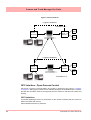
PC Ethernet connections.......................................................................................
Getting connected - IP Address.............................................................................
Local Area Network setup .....................................................................................
Links to Remote Networks .....................................................................................
OPC Interface - Open Process Control.................................................................
OPC Clients ..........................................................................................................
Web Browser..........................................................................................................
iv
135
135
136
136
137
138
139
140
142
142
43-TV-25-30 Iss.2 GLO June 06 UK
Communications Server
............................................................................. 143
Comms Server Overview ...................................................................................... 143
Comms Server Status Screen ................................................................................ 146
Comms Server Setup ............................................................................................. 149
Comms Server Database
............................................................................ 152
System Setup ......................................................................................................... 153
Section 9: PC Software Suite .........................................................................155
The TrendManager Pro Software Suite ................................................................ 155
Section 10: Spares List ...................................................................................157
Minitrend QX Recorder ........................................................................................ 157
Multitrend SX Recorder ........................................................................................ 161
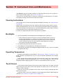
Section 11: Instrument Care and Maintenance .............................................167
Cleaning Instructions ................................................................................. 167
Backlights .................................................................................................. 167
Operating Temperature .............................................................................. 167
Touch Screen ............................................................................................. 167
Calibration ................................................................................................. 168
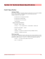
Section 12: Technical Data & Specifications ................................................169
Field IO Specification ................................................................................ 169
Analogue Input .......................................................................................... 170
Alarm/Digital Input Specification ............................................................. 170
Alarm/Relay Output Card Options ....................................................................... 170
Digital Input Cards............................................................................................... 171
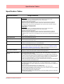
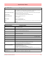
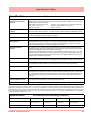
Specification Tables
................................................................................... 173
Specification
Design Attributes .......................................................
Specification
Analogue Inputs ..........................................................
Specification
Logging ..................................................................
Specification
Physical Parameters...................................................
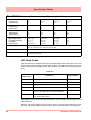
Input Range Performance Accuracy Table...........................................................
Input Actuation
(Linear) .................................................................................................................
Specification
Options................................................................
Specification
Environmental and Operating Conditions..........................
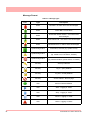
LED Flash Codes..................................................................................................
173
175
176
176
177
177
178
179
180
Appendix A: Quality and Safety .....................................................................181
CE Mark ..................................................................................................... 181
Safety ......................................................................................................... 181
Appendix B: Maths Expressions ....................................................................183
Full Maths & Script Processing
................................................................. 183
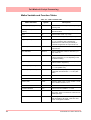
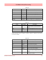
Maths Variable and Function Tables ....................................................................
Full Maths.............................................................................................................
Script Function Application Examples .................................................................
Maths Error Messages..........................................................................................
43-TV-25-30 Iss.2 GLO June 06 UK
184
190
191
195
v
Appendix C: Thermocouple Connections .................................................... 197
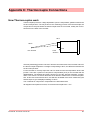
How Thermocouples work .........................................................................197
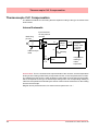
Thermocouple CJC Compensation .............................................................198
Internal Automatic ................................................................................................
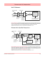
Ext 0°C Reference .................................................................................................
External with a Specified Temperature .................................................................
External Input Reference.......................................................................................
198
199
199
200
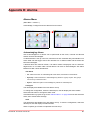
Appendix D: Alarms ....................................................................................... 201
Alarms Menu ......................................................................................................... 201
Appendix E: Ethernet ..................................................................................... 203
Ethernet ................................................................................................................. 203
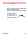
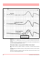
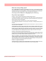
Appendix F: Fuzzy Logging ........................................................................... 205
Appendix G: F sub zero Sterilisation ............................................................ 209
The significance of F0 ........................................................................................... 209
Appendix H: Calibration ................................................................................. 211
AI Calibration and CJC Calibration ...........................................................211
Sensor Compensation .................................................................................211
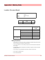
Appendix I: Battery Data ................................................................................ 213
Location: Processor Board
.........................................................................213
Safety Guidelines................................................................................................... 213
Appendix J: Function Codes and Memory Maps ........................................ 215
Modbus Memory Map Supplement:
...........................................................215
Totalisers ...............................................................................................................
Input Text message ................................................................................................
Analogue Input Value ............................................................................................
Communications Input ..........................................................................................
Pen Values .............................................................................................................
Modbus Function Codes
215
215
216
216
216
.............................................................................216
Index ................................................................................................................ 217
vi
43-TV-25-30 Iss.2 GLO June 06 UK
Section 1: Preface
Preface
Thank you for choosing a Honeywell X Series recorder
Thank you for purchasing the newest in our range of electronic data recording for Honeywell X Series Advanced Graphic Recorders.
The Minitrend QX and Multitrend SX paperless chart recorders are the latest development of the solid-state replacement for traditional paper recorders.
Many options, features and functions are available to meet a wide range of applications and
requirements including: Power, Water Treatment, Thermal Processing, Food and Beverage,
Pharmaceutical/Biotech and Manufacturing industries.
This manual explains the product functionality operation, configuration and communication
as well as Safety Precautions, Installation & Wiring, Recorder Setup, Troubleshooting and
Spares List. It is recommended that the user reads the manual before installing and operating the recorder.
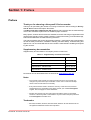
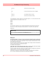
Supplementary documentation
Supplementary documentation to accompany these recorders are:
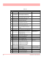
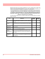
Table 1.1 : Supplementary recorder documentation
Manual
Part number
TrendManager Pro V5 & X Series Software Suite
43-TV-25-11
Screen Designer X Series Recorders
43-TV-25-31
Specification - Minitrend QX
43-TV-03-10
Specification - Multitrend SX
43-TV-03-11
Documents can be downloaded from the web site at www.XSeries-info.net .
Notes
• The contents of this manual are correct at the time of issue. The contents may
change at any time without prior notification. This is due to continuous developments to the recorder and it’s functionality.
• Every effort has been made to ensure the accuracy of this document, however
should there be any anomalies found, please contact your nearest Honeywell
supplier. See back page for contact addresses.
• All rights are reserved. No part of this manual should be copied or reproduced,
stored on a retrieval system or transmitted in any form without the prior permission
from Honeywell International Inc.
Trademarks
• Microsoft, MS-DOS, Windows, Windows 2000, Windows XP and Windows CE are
all registered trademarks of Microsoft Corporation.
43-TV-25-30 Iss.2 GLO June 06 UK
1
Safety
• Compact Flash® and CF (logo) are trademarks of the Compact Flash Association
(CFA).
• For the purpose of this manual the ™ and ® symbols will not follow their own trademark names or registered trademark names in every instance.
• Company names and Product names mentioned in this manual are trademarks or
registered trademarks of their individual owners.
Safety
The X Series range of instruments is compliant with the requirements of BS EN 610101:2001 “Safety Requirements for Electrical Equipment for Measurement, Control and Laboratory Use” and UL 61010C-1 and CSA 22.2-1010.1, as options. If the equipment is used in
a manner not specified, the protection provided by the equipment may be impaired.
The X Series range of instruments is compliant to the requirements for Class 1, Div.2 Hazardous (Classified) Locations.
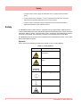
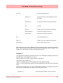
Symbols
One or more of the following symbols may appear on the recorder labelling.
Table 1.2 : Safety Symbols
Symbol
Meaning
Caution - refer to manual for
instructions
Caution - risk of electric
shock
Direct Current
Protective conductor terminal
Earth (ground) terminal
Static Electricity
2
43-TV-25-30 Iss.2 GLO June 06 UK
Protocols used in this manual
Table 1.2 : Safety Symbols
Symbol
Meaning
Directive 2002/96/EC
WEEE: Waste Electrical and
Electronic Equipment
Static Electricity
All circuit boards and electronic modules associated with this recorder contain components
which are susceptible to damage caused by electrostatic discharge. Should it be necessary
to handle such components, appropriate precautions in accordance with ANSI/ESD S20.20
Electrostatic Discharge Control Program Standard, should be observed.
Protocols used in this manual
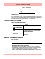
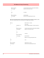
Safety and Symbol Identification
Table 1.3 :
Symbol
Description
WARNING
The WARNING symbol indicates a potentially
hazardous situation, which, if not avoided, could
result in death or serious injury.
CAUTION
This CAUTION symbol may indicates a potentially hazardous situation, which, if not avoided, may
result in property damage.
NOTICE
A NOTICE symbol indicates important information that must be remembered and aids in job
performance.
Warnings and Safety Precautions
Do’s and Don’ts
1. Before any connections are made to the recorder, ensure the protective earth terminal
is connected to a protective conductor before applying power or any other connections.
WARNING
IMPROPER INTERRUPTION OF CONNECTIONS
Any interruption of the protective conductor outside the recorder, or disconnection of
the protective earth terminal is likely to make the recorder dangerous under some fault
conditions. Intentional interruption of the protective conductor is dangerous.
Failure to comply with these instructions could result in death or serious injury.
43-TV-25-30 Iss.2 GLO June 06 UK
3
Warnings and Safety Precautions
In order to comply with the requirements of safety standard EN 61010-1:2001, the
recorder should have one of the following as a disconnecting device, located within
easy reach of the operator, and be clearly labelled as the disconnecting safety device:
• A switch or circuit breaker which complies with the requirements of IEC 60947-1 and
IEC 60947-3.
• A separable coupler which can be disconnected without the use of a tool.
• A separable plug, without a locking device, to mate with a socket outlet in
the building.
2. Whenever it is likely that protection has been impaired, the recorder should be made
inoperative and secured against operation. The manufacturer's service centre should
be contacted.
3. Repair is not to be attempted by a customer. Any adjustment or maintenance expected
of an operator as part of the normal operation of the product is referred to as Operational Maintenance. Any maintenance not expected of the operatoris referred to as
Corrective Maintenance and is to be carried out only by authorized service personnel
or returned to an authorized repair centre.
4. Where conductive pollution such as condensation or conductive dust is present, adequate air conditioning, filtering and/or sealing must be installed.
5. This recorder contains one battery on the Processor board which must be treated and
disposed of with care. Batteries must not be short circuited. Batteries should be disposed of in accordance with local regulations, they must not be disposed of with normal
refuse.
6. Improper signal and supply wiring - WARNING
WARNING
IMPROPER SIGNAL AND SUPPLY WIRING
Signal and supply wiring should be kept separate. Where this is impractical, shielded cables should
be used for the signal wiring. Where signal wiring is carrying, or could carry under fault conditions,
hazardous voltage (defined as >30 V rms and 42.4 V peak, or >60 Vd.c.), double insulation must
be used for all signal wiring.
Failure to comply with these instructions could result in death or serious injury.
7. If the equipment is used in a manner not specified by the manufacturer, the protection
provided by the equipment may be inadequate.
8. The protective earth terminal must remain connected (even if the recorder is isolated
from the mains supply) if any of the measuring, communications, or relay terminals are
connected to hazardous voltages.
Hazardous Voltage
Hazardous Voltages are defined by EN61010-1 as follows:
WARNING
HAZARDOUS VOLTAGE LEVELS
Voltage levels above 30V rms and 42.4V peak or 60V dc are deemed to be
"Hazardous Live".
Failure to comply with these instructions could result in death or serious injury.
4
43-TV-25-30 Iss.2 GLO June 06 UK
Section 2: Installation
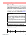
Damage checks
Any damage caused to the recorder or the contents should be reported immediately to your
shipper.
Unpacking
Remove the contents, check the packaging and remove all documentation and accessories
supplied. Retain the box and any packaging for future transportation.
Contents
Check that the contents and accessories are correct against the order or Model Selection
Guide using the model number on the recorder. Contact your authorised Honeywell distributor or Honeywell immediately should there be any query.
The contents are based on Unit Model Number ordered and will vary from unit to unit. The
following list is provided as a general guide and not specific to any single unit.
• Recorder - specification as ordered (check against the Model Selection Guide)
• Mounting fixings - Mounting clamps and panel gasket
• Connector kit - mating half connectors to recorder spec. Including a CJC connector for
Thermocouple operation.
• Quick Start Guide - to get you started
• First time Password system instructions - for ESS recorders only
• CD - Viewer software + documentation
• Plastic stylus x 2 (for use with the touch screen)
• Manual (optional) - Hardcopy English, French or German
• Any other items ordered as an option (Table VI in the Model Selection Guide)
Re-packing
NOTICE
Should the original packing be destroyed or lost, new packaging can be ordered or as a
last alternative, then ONLY pack the recorder in polystyrene granules if the recorder is
FIRST sealed in a strong plastic bag. Failure to do this will invalidate your warranty.
Environment and Location
• The recorder is designed to be mounted into a panel. See “Installation Instruc-
tions” on page 9.
• Mount in a suitable location where the ideal viewing angle will not exceed 65° from
the left or right, 65° looking down and 40° looking up at the recorder display.
• The location should be free from vibration.
• The environment should be of non-condensing humidity.
• The ambient temperature should be between 0°C and 50°C.
• The relative humidity should be between 10% to 90%.
43-TV-25-30 Iss.2 GLO June 06 UK
5
Mechanical Installation
Mechanical Installation
Mounting and Viewing Angles
Both the Minitrend QX and Multitrend SX recorders have an unlimited mounting angle. For
the best view of the display the viewing angle should not exceed 65° from the left or right, 65° look-
ing down and 40° looking up at the recorder display.
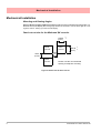
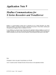
Panel cut-out size for the Minitrend QX recorder
138.00
(5.43”)
Panel
Cut-out
+1
-0
Panel
Cut-out
138.00
(5.43”)
+1
-0
>7.00
(0.28”)
>6.00
(0.237”)
Panel
Cut-out
Please note the recommended
spacing for adjacent mounting
Figure 2.1 Minitrend QX Panel cut-out
6
43-TV-25-30 Iss.2 GLO June 06 UK
Mechanical Installation
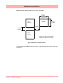
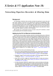
Panel cut-out size for the Multitrend SX recorder
281.00
(11.06”)
Panel
Cut-out
Panel
Cut-out
281.00
(11.06”)
>20.00
(0.787”)
>20.00
(0.787”)
Panel
Cut-out
Please note the recommended
spacing for adjacent mounting
Figure 2.2 Multitrend SX Panel cut-out
The Minitrend QX and Multitrend SX recorders are DIN Standard sizes and should be panel mounted.
43-TV-25-30 Iss.2 GLO June 06 UK
7
Mechanical Installation
Minitrend QX
Dimension details
4 Mounting clamp positions. For standard units fit only two
brackets on opposite sides of the unit, either top and bottom
or left and right slots. NEMA 4X rated recorders require all four
mounting brackets to be fitted.
Figure 2.3 Minitrend QX Recorder dimensions
8
43-TV-25-30 Iss.2 GLO June 06 UK
Mechanical Installation
Multitrend SX
Dimension details
4 Mounting clamp positions. For standard units fit only
two brackets on opposite sides of the unit, either top
and bottom or left and right slots. NEMA 4X rated recorders require all four mounting brackets to be fitted.
Figure 2.4 Multitrend SX recorder dimensions
Installation Instructions
• Minimum panel thickness = 2mm (0.078”), max = 20mm (0.78”)
• Both recorders must be inserted from the front of the panel,
• Two mounting clamps are supplied and can be fixed either on the top and bottom
sides or on the left and right sides of the case.
43-TV-25-30 Iss.2 GLO June 06 UK
9
Mechanical Installation
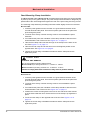
Panel Mounting Clamp Installation
The Minitrend QX and the Multitrend SX recorders slide into the panel cut-out and are held
in place by two (or four) panel clamps. The panel clamps should be fitted on diagonally opposite sides of the unit and tightened against the rear of the panel using two fixing screws.
The mounting clamp assembly and fitting instructions differ slightly for the two recorders.
Minitrend QX
1. Insert the panel gasket onto the recorder so it goes between the back of the
recorder bezel and the panel. From the front panel, place unit in the panel and
push through the panel.
2. To loosen each clamp, unscrew the long screw to accommodate the panel
thickness.
3. From behind the panel, the orientation of the clamp should be with the screw
head towards the rear of the unit. See Figure 2.1 on page 11
4. Take the first clamp and locate the two lugs on the clamp into the slots on the
unit. See Figure 2.1 on page 11
5. Take the second clamp and do the same but in the diagonal position to the
opposite side. See Figure 2.3 on page 8
6. Tighten the screw using a flat blade screwdriver and the clamp will secure
against the panel.
CAUTION
CONTROL UNIT DAMAGE
Do not over tighten mounting clamp screws.
Minitrend QX torque setting should be 0.5 - 0.75Nm/4.4 - 6.6lbf-in
Multitrend SX torque setting should be 0.5 - 0.70Nm/4.4 - 6.2lbf-in
Failure to comply with these instructions may result in product damage
Multitrend SX
1. Insert the panel gasket onto the recorder so it goes between the back of the
recorder bezel and the panel. From the front panel, place unit in the panel and
push through the panel.
2. To loosen each clamp, unscrew the long screw to accommodate the panel
thickness.
3. From behind the panel, the orientation of the clamp should be with the screw
head towards the rear of the unit. See Figure 2.2 on page 11
4. Position the circular mounting boss in the hole on one side of the case with the
lip of the boss inside the case. Ensure the front of the clamp is up against the
panel.
5. Fix the second clamp on the opposite side of the unit. See Figure 2.4 on
page 14
6. Tighten the screw using a flat blade screwdriver and the clamp will secure
against the panel.
10
43-TV-25-30 Iss.2 GLO June 06 UK
Mechanical Installation
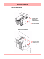
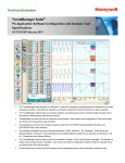
Mounting Clamp Diagram
Figure 2.1 QX Mounting clamp
2 mounting clamp
positions, one required on either side
of the unit
Mounting clamp slots
Figure 2.2 SX Mounting clamp
4 mounting clamp
positions (2 shown).
2 clamps are required on opposite
sides of the unit
43-TV-25-30 Iss.2 GLO June 06 UK
11
Electrical Installation
Electrical Installation
Installation Category
• Installation category - Installation category II, Pollution degree 2
• Follow National and local electrical codes for installation in a Class 1, Div.2 area.
For voltage, frequency and power refer to the appropriate Specification sheet: See “Section 12: Technical Data & Specifications” on page 169.
Fuses
There is a fuse situated on the DC input version power supply, type 2A time-delay, this can
be replaced by the user. Replacement of fuses should be carried out by qualified service
personnel.
If the fuse should blow again there is probably a problem elsewhere within the unit and the
recorder should be returned for inspection to your authorised Honeywell distributor or Honeywell Service department.
Cables
To fully comply with the requirements of the CE Mark, all cables connected to the rear of
the unit should use screened cable terminated at both ends. A low impedance earth cable
(<50 mΩ) must be connected to the earthing stud on the rear of the recorder, to ensure
that the recorder is always earthed.
Before performing any installation please read the section on “Safety” on page 2.and
“Warnings and Safety Precautions” on page 3.
All connections to the unit are made via the rear panel, the layout of which is shown in Figure 2.3 on page 13
Signal Wiring
WARNING
ENSURE SAFETY EARTH CONNECTION
Always ensure the unit is connected to safety earth when connecting to an AC or DC
supply.
Failure to comply with these instructions could result in death or serious injury.
The Honeywell recorder is intended for panel-mount use, and only the front face is intended to be exposed to the operator. Disconnection from the supply MUST be made possible
by means of a switch, circuit breaker or other means of supply isolation. The disconnection
device must be included in the panel installation, clearly marked, in close proximity to the
Honeywell equipment, and within easy reach of the operator. The protective earth terminal must remain connected (even if the recorder is isolated from the mains supply) if any
of the analogue or relay terminals are connected to hazardous voltage.
12
43-TV-25-30 Iss.2 GLO June 06 UK
Electrical Installation
WARNING
HAZARDOUS VOLTAGES
When using the recorder as portable equipment the optional rear cover must be fitted
when hazardous voltages are connected.
Failure to comply with these instructions could result in death or serious injury.
AC Power
AC supply is connected via the standard configuration IEC chassis plug on the rear panel,
100 - 250 Vac, 50-60 Hz (40 VA Minitrend QX , 60VA Multitrend SX ).
Absolute limits 90V-132Vac and 180V-264Vac
24V DC Power / 24V AC Power
Supply range is 24V DC +/- 10% (absolute limits are 20V to 50V DC). Also accepts 20 to
30V AC. Power to the D.C.variant is connected via a rectangular 3-way connector as identified in Figure 2.3 on page 13 for the Minitrend QX and Figure 2.4 on page 14 for the
Multitrend SX .
Wire seal provision
Earth screw
(ground)
AC supply
100 - 250 VAC
24V DC/AC Input
SPNC Relay
Analogue Input /
Analogue Output /
or Pulse Input
Slot A
Slot B
24V TX
Power
Supply
Output
CJC Sensor
Alarm Relay or
Digital I/O
Slot G
Ethernet
RS485
USB Host
Figure 2.3 QX Connector diagram
43-TV-25-30 Iss.2 GLO June 06 UK
13
Electrical Installation
Card and Slot positions
Table 2.1 : Card priority positions
Cards
Minitrend QX
Multitrend SX
Analogue Input card
A, B
A, B, C, D, E, F
Analogue Output card
B
E, F
Pulse Input card
A, B
A, B, C, D, E, F
Alarm Relay or Digital I/O card
G
G, H, I
AC supply
100 - 250 VAC
Earth screw
(ground)
Analogue Input/
Analogue Output/
or Pulse Input
Slot A
24V DC/AC Input
Slot B
Slot C
SPNC
Relay
Slot D
Slot E
Slot F
24V TX
Power Supply
Output
Alarm Relay
or
Digital I/O
LED
Slot G
CJC Sensor
position in the
middle of the
Analogue Input
connector.
Slots A - F
Slot H
Slot I
Ethernet
RS485
USB Host
Figure 2.4 SX Rear panel
14
43-TV-25-30 Iss.2 GLO June 06 UK
Electrical Installation
Analogue Input Card
Each Analogue Input card has up to 8 input channels. Connections are made via 2 x 12way screw terminal plugs that fit into a PCB header on the rear of the unit. The 2-way CJC
sensor should remain fitted in the central 2-way header.
The Minitrend QX can have two analogue input cards fitted giving up to 16 input channels
(2 x 8 channel cards). The slot positions are A & B, these are identified on the rear panel on
the back of the unit. Either slot can be used, it is recommended that slot A is used if only one
card is fitted.
The Multitrend SX can have up to 6 analogue input cards fitted, up to 48 input channels.
The slot positions A, B, C, D, E or F; these are identified on the rear panel. PC boards are
fitted in order, slot ”A” starts from the top.
For more information of setting up calibration for an Analogue card, see “Calibration” on
page 71.
WARNING
HAZARDOUS VOLTAGES
Insulation from channel to channel: Normally a channel can be safely connected to a
hazardous voltage up to 300V AC common mode* with respect to earth. However,
where a channel is connected to a safety low voltage circuit, an immediately adjacent
channel must be adequately insulated from hazardous voltages between 150V AC
and 300V AC max. This insulation should comprise of at least 1.5mm air gap, or a barrier rated greater than 1400V AC. This is to ensure that protection of the safety low
voltage circuit is fully maintained.
*Common Mode voltage is a voltage applied between the whole channel and earth,
not between pins on a channel. 300V AC is permitted at Measurement Category CAT
ll (Overvoltage Category ll)
Failure to comply with these instructions could result in death or serious injury.
NOTICE
For 12 and 24-way connectors; torque setting 0.4 Nm/3.5lbf-in. Do not over tighten.
Recommended wire size for termination connector is 22-12 AWG (22-14 SWG)
Analogue Input Channel Numbers
Analogue Input cards are either 4, 6 or 8 channels with a full length connector taking up 8
channels even if only 4 or 6 are operational.
Table 2.2 :
Analogue Input card
Card
Position
Slot A
Slot B
Slot C
Channel
number
1 to 8
9 to 16
17 to 24
43-TV-25-30 Iss.2 GLO June 06 UK
Slot D
25 to 32
Slot E
Slot F
33 to 40
41 to 48
15
Electrical Installation
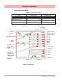
Analogue Input Connection Details
Current Input
For Current (mA) Input fit a 10Ω resistor across the + and - pins of the 12-way mating half
analogue connector. Figure 2.6 on page 16 shows a 10Ω (±0.1%) resistor fitted to channel 5 for a current (mA) input.
Thermocouples
Ensure polarity of thermocouple is correct.
Resistance Thermometers
If using 2 or 3 wire R/T the + and - terminals must be linked together. See Figure 2.6 on
page 16.
Analogue Input Signal Wiring
Figure 2.5 Analogue Input connector
CJC
CH1
CH2
CH3
CH4
CH5
CH6
CH7
CH8
Figure 2.6 Input signal wiring
Volts/mV
Active Burnout
Thermocouples
Passive Burnout
Thermocouples
Current
10R
-ve
+ve
Ohms
-ve
+ve
4-wire R/T
-ve
+ve
3-wire R/T
-ve
+ve
2-wire R/T
+ve optional
connection
R/T
16
R/T
R/T
43-TV-25-30 Iss.2 GLO June 06 UK
Electrical Installation
CAUTION
CONTROL UNIT DAMAGE
Do not apply a hazardous live voltage between + and - pins within a channel. (eg. 60V
maximum on voltage ranges, 1.2V maximum on millivolts ranges). Do not apply a voltage above 1.2V to the * pin.
Failure to comply with these instructions may result in product damage
CJC Connectors
The CJC connector resides between channel 4 and channel 5 on the Analogue Input card.
For information on connecting the CJC sensor, see Figure 2.5 on page 16.
Analogue Output Card
The Analogue Output card connections are made via 1 x 12-way screw terminal plug that
fits into a PCB header on the rear of the unit.
The Analogue Output card position for the Minitrend QX is shown in Figure 2.3 on
page 13, and Figure 2.4 on page 14 for the Multitrend SX .
WARNING
HAZARDOUS VOLTAGES
Insulation from channel to channel: Normally a channel can be safely connected to a
hazardous voltage up to 300V AC common mode* with respect to earth. However,
where a channel is connected to a safety low voltage circuit, an immediately adjacent
channel must be adequately insulated from hazardous voltages between 150V AC and
300V AC max. This insulation should comprise of at least 1.5mm air gap, or a barrier
rated greater than 1400V AC. This is to ensure that protection of the safety low voltage
circuit is fully maintained.
*Common Mode voltage is a voltage applied between the whole channel and earth, not
between pins on a channel. 300V AC is permitted at Measurement Category CAT ll
(Overvoltage Category ll)
Failure to comply with these instructions could result in death or serious injury.
Analogue Output Channel Numbers
The Analogue Output cards are either 2 or 4 channels using a connector that only takes up
half the length of the connector slot. Looking from the rear of the unit the Analogue Out connector is on the left of the Analogue slot with a blanking plate on the right.
43-TV-25-30 Iss.2 GLO June 06 UK
17
Electrical Installation
Table 2.3 :
Analogue Output card
Card
Position
Slot B
Slot E
Slot F
Channel
number
9 to 12
33 to 36
41 to 44
Output 3
Output 4
Analogue Output Connection Details
Output 1
1
2
3
Output 2
4
5
6
7
8
9 10 11 12
Loop + Loop Loop +
Loop NC
NC
Loop +
Loop NC
Loop +
Loop NC
NC = Not connected
Pulse Input Card
The Pulse Input card connections are made via 1 x 12-way screw terminal plugs that fits
into a PCB header on the rear of the unit.
The Pulse Input card position for the Minitrend QX is shown in Figure 2.3 on page 13,
and Figure 2.4 on page 14 for the Multitrend SX .
WARNING
HAZARDOUS VOLTAGES
Insulation from channel to channel: Normally a channel can be safely connected to a
hazardous voltage up to 300V AC common mode* with respect to earth. However,
where a channel is connected to a safety low voltage circuit, an immediately adjacent
channel must be adequately insulated from hazardous voltages between 150V AC
and 300V AC max. This insulation should comprise of at least 1.5mm air gap, or a barrier rated greater than 1400V AC. This is to ensure that protection of the safety low
voltage circuit is fully maintained.
*Common Mode” voltage is a voltage applied between the whole channel and earth,
not between pins on a channel. 300V AC is permitted at Measurement Category CAT
ll (Overvoltage Category ll)
Failure to comply with these instructions could result in death or serious injury.
18
43-TV-25-30 Iss.2 GLO June 06 UK
Electrical Installation
Pulse Input Channel Numbers
The Pulse Input card has channels using a connector that only takes up half the length of
the connector slot. Looking from the rear of the unit the Pulse Input connector is on the right
of the slot with a blanking plate on the left.
Table 2.4 :
Pulse Input card
Card
Position
Slot A
Slot B
Slot C
Slot D
Slot E
Slot F
Channel
number
1 to 4
9 to 12
17 to 20
25 to 28
33 to 36
41 to 44
Pulse Input Connection Details
Do not connect anything to terminals marked NC (Not Connected). For Frequency and Voltage levels see “Specification Tables” on page 173.
Channel 1
Channel 2
-
-
+
NC
+
NC
Channel 3
-
+
NC
Channel 4
-
+
NC
Transmitter Power Supply Card
The Minitrend QX Transmitter power supply option is
24V DC 200 mA and is fitted to the power supply card
within the unit. Connection is made via a 2-way connector
at the rear of the unit, the mating half is supplied with this
option. For connector position see Figure 2.3 on
page 13. The 24V transmitter power supply is not isolated from the recorder, and is not referenced to ground
24V
0V
Minitrend 24V DC TXP
The Multitrend SX Transmitter power supply option is 24V DC 1 A and is fitted below the
power supply card within the unit. Connection is made via two 10-way connectors, see Figure 2.4 on page 14, mating halves supplied with this option. The Multitrend SX transmitter
power supply is isolated from the recorder.
A red LED light will illuminate when there is voltage on the connectors this is situated between the two connectors at the back of the unit. Figure 2.4 on page 14.
Recommended wire size for termination connector 22-12 AWG (22-14 SWG).
43-TV-25-30 Iss.2 GLO June 06 UK
19
Electrical Installation
24V
LED
0V
Figure 2.7 Transmitter Power Supply card for the SX recorder
Alarm Relay Cards & Digital Input/Output Cards
The Alarm Relay Cards and the Digital Input/Output Cards are both options available for
the Minitrend QX and the Multitrend SX recorders.
All Alarm Relay card inputs provide 240V AC isolation channel to channel and channel to
recorder. Digital Input/Outputs will provide isolation to 100V AC test voltage (not for mains
connection).
All digital inputs have volt free contacts, and are sampled at 10Hz max.
The Minitrend QX has only one slot available for digital inputs and relay outputs for either
a 4 or 8 channel Alarm Relay card or an 8 or 16 channel Digital I/O card fitted in slot G, the
position is identified on the rear panel.
The Multitrend SX can have up to three Alarm Relay cards fitted in any combination of
Alarm Relay card or Digital I/O cards. The first Alarm Relay card or Digital I/O card is fitted
in slot G, any additional cards will locate in positions H and I.
WARNING
HAZARDOUS VOLTAGES
Digital Input/Output card channels must not be connected to any hazardous live voltages (no higher than 30V AC rms or 60V DC).
Alarm Relay Card channels
Alarm Relay Card channels can be connected to hazardous voltages up to 300V AC,
at Measurement Category CAT II (Overvoltage Category II)
Failure to comply with these instructions could result in death or serious injury.
20
43-TV-25-30 Iss.2 GLO June 06 UK
Electrical Installation
NOTICE
For 12 and 16-way connectors; torque setting 0.4 Nm/3.5lb-in. Do not over tighten.
Recommended wire size for termination connector is 22-12 AWG (22-14 SWG)
4 and 8 Alarm Relay Cards
The 24-way connector for the Alarm Relay Card , connects to 3 A, 240 VAC SPCO relays.
The pin-outs for 4 and 8 relay Alarm Relay cards are numbered from left to right and they
read as follows for each channel; NC (normally closed), C (common), NO (normally open).
Devices driven by the relays are connected via two 12-way screw terminal plugs.
The last two channels, 7&8, 23&24 or 39 & 40, can be used as digital inputs, connect across
Common (C) and Normally Open (NO).
CAUTION
IMPROPER MAINS SWITCHING
For 8 channel Alarm Relay cards.
Switching mains on the normally-open contact on channels 7 and 8 is not recommended,
as surges and spikes on the mains supply could cause damage to the input circuitry.
The normally-closed contact is unaffected, and can be used like all the other channels.
A Form C dry contact relay is used for this type of card. The inputs are designed to accept
“Dry contact, no volt inputs”. The relays should be used for non-inductive loads only/
Where a device requires a voltage to operate it, such as a 12 Volt buzzer, connect it to the
normally open (NO) contacts (unless the fail-safe setting is activated).
The maximum voltage which may be used with the alarm relays is 240V
Alarm Relay Channel Numbers
The Alarm Relay cards are either 4 or 8 channels with a full length connector taking up 8
channels even though the cards only operate on 4 channels or 8 channels. The 8 channels
Alarm Relay card has 2 digital inputs available on the last 2 channels. There are no Digital
Inputs available on the 4 channels Alarm Relay card.
Table 2.5 :
Alarm Relay card 4 channel
Alarm Relay card 8 channel
Card
position
Channel
number
Digital
Inputs
Card
position
Channel
number
Digital
Inputs
Slot G
1 to 4
N/A
Slot G
1 to 8
7&8
Slot H
17 to 20
N/A
Slot H
17 to 24
23 & 24
Slot I
33 to 36
N/A
Slot I
33 to 40
39 & 40
43-TV-25-30 Iss.2 GLO June 06 UK
21
Electrical Installation
Figure 2.8 Alarm Relay Card connector details
CH 1
CH 2
CH 3
CH 4
CH 5
CH 6
CH 7
CH 8
NC C NO NC C NO NC C NO NC C NO NC C NO NC C NO NC C NO NC C NO
Relay contacts position
Channels 7 and 8 can
be set as Digital Inputs.
(Use C and NO)
NC = Normally Closed
C = Common
NO = Normally Open
8 and 16 Digital Input/Output Card
The Digital Input/Output Card has 1A 24V DC rated relays that are connected via two 16way connectors, the left connector for the first 8 channels and right connector for the second
8 channels. The pin-outs for 8 and 16 I/O cards are labelled from left to right, 1 to 16 on the
left side and 17 to 32 on the right. Each channel can be set up as an input or an output. For
output the relay is normally open type.
A Form A dry contacts relay is used for this type of card. The inputs are designed to accept
“Dry contact, no volt inputs”.
NOTICE
For Digital Inputs, short together the 2 pins of the channels with a switch or a relay.
.
Figure 2.9 Digital Input/Output card connector details
CH1 CH2 CH3 CH4 CH5 CH6 CH7 CH8
1 2 3 4 5 6 7 8 9 10 11 12 13 14 15 16
NO C NO C NO C NO C NO C NO C NO C NO C
CH9 CH10 CH11 CH12 CH13 CH14 CH15 CH16
17 18 19 20 21 22 23 24 25 26 27 28 29 30 31 32
NO C NO C NO C NO C NO C NO C NO C NO C
NO = Normally Open
C = Common
22
43-TV-25-30 Iss.2 GLO June 06 UK
Electrical Installation
Digital Input Card Channel Numbers
The Digital input cards are either 8 or 16 channels with a full length connector taking up 16
channels even if only 8 channels are in operation. Both the digital input cards can be used
as a relay card if required.
Table 2.6 :
Digital Input card 8 channel
Card
position
Channel
number
Digital Input card 16
channel
Card
position
Channel
number
Slot G
1 to 8
Slot G
1 to 16
Slot H
17 to 24
Slot H
17 to 32
Slot I
33 to 40
Slot I
33 to 48
Communications Connections
RS485
The RS485 port uses a 3-way connection. After connection, select the RS485 port from the Comms menu and
select the required protocol from the Protocol menu eg.
Modbus. Diagram shows a view looking from the rear of
the unit. See “Comms Menu” on page 61.
1
2
3
+A -B GND
Ethernet
The Ethernet port uses a standard RJ45 Ethernet connection. After connection, select the
Ethernet port from the Comms menu and select the required protocol from the Protocol
menu eg.Modbus.
2
RD+
TDTD+
RD-
8 7 6 5 4 3 2 1
1
4
3
6
5
8
7
A
B
RJ45 Pin 1 is to the right
from the rear of the unit
24V DC Instrument Power Input
3-way connector. Diagram shows a view looking from the rear
of the unit.
43-TV-25-30 Iss.2 GLO June 06 UK
1
2
3
+
- GND
23
Electrical Installation
SPNC Relay
(Single Pole Normally Closed). 2-way connector. This is a fail safe
relay which means if the power goes off the relay closes and can be
set to trigger an alarm. So should the power fail the relay is in a “fail
safe” condition. Diagram shows a view looking from the rear of the
unit. Either pins can be Common or Normally closed.
1
2
NOTE: Once the recorder is powered up, if there are no active alarms associated with the
“Fixed Relay”, the contacts will open. When the alarm is on they will close
USB Devices
For a list of the latest compatible USB devices, go to: www.XSeries-info.net
Print Support
Print Support is a firmware option that can be activated using the credit system, refer to the
Options item in “Credits” on page 70.
Not all printers will be compatible with the print support feature on the recorder. The guidelines are they must be a USB printer that shows as a standard PCL (printer control language). The system will not support multi function devices or printers that require specific
drivers. Avoid photo printers and printers that allow stand alone operation with cameras or
media specific printers such as pictbridge.
There isn’t a constant factor to which printers work and those that wont. We recommend that
you follow the guidelines outlined here and plug it in and see.
Examples of printers that are compatible with the system are:
• HP Deskjet 995C
• HP Photosmart 7760
• HP Laserjet 1022n
• HP Laserjet 1300
• HP Deskjet 970Cxi
• HP Deskjet 450cbi
To set up your printer configuration go to “Printer Menu” on page 75.
Keyboards
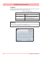
All keyboards are native USB keyboards. Local keyboard layouts are not supported; all keyboards are recognised as US layout (QWERTY).
Cordless keyboards and mice are not supported :
• Dell Model # SK-8115 Keyboard
• IBM ACC42 with USB hubs
• Dell Model # C-BG17-Dual Cordless
Keyboard and Mouse Combination
• IBM SK-8815 with USB hubs
• Logitech Model # LX300 Cordless
Keyboard and Mouse Combination
• IBM SK-8806 with USB hubs
Barcode Reader
Most USB barcode readers emulate keyboards and cause no recognition problems. Exemples of tested barcode readers are::
24
• Peninsula Phoenix 2
• Wasp - WWR 2905 Pen Scanner
• Quick Scan QS2500
• Barcode Traders LC4400 Series
43-TV-25-30 Iss.2 GLO June 06 UK
Section 3: Overview
Functions and Features
.
Up to 16 Analogue Inputs
for the Minitrend QX and
up to 48 for the Multirend
SX
•
•
•
•
•
•
QX - Up to 192 “soft alarms”
- 6 per pen
SX - Up to 576 “soft alarms”
- 6 per pen
Data Storage media:
• Compact Flash - up to 2Gb
• USB ports for keyboard,
mouse and storage
mA (external shunt)
ohms
Volts
mV
Thermocouple
RTD
QX - Up to 32 Totalisers
(1 per pen)
SX - Up to 96 Totalisers
(1 per pen)
QX - Up to 4 Analogue Outputs
SX - Up to 8 Analogue Outputs
Fast Scanning Mode
(QX = 8 Inputs, SX = 16 inputs)
QX - Up to 8 Pulse Inputs
SX - Up to 24 Pulse Inputs
24V Power Supply
QX - Up to 8 Relay Alarm Outputs
SX - Up to 24 Relay Alarm Outputs
24V Transmitter Power
Supply
QX - Up to 16 Digital Inputs /
24V Outputs
SX - Up to 48 Digital Inputs /
24V Outputs
Common Relay Output
Communications:
• TCP/IP, RS485 Modbus (slave)
• 10/100 Ethernet, Web and FTP
• USB ports for keyboard and mouse
Key:
Standard
Option
• OPC Server
Crystal Clear Display
• Minitrend QX has a 5.5” Digital Colour LCD (TFT), QVGA Resolution (320 x 240 pixels)
• Multitrend SX has a 12.1” Digital Colour LCD (TFT), SVGA Resolution (800 x 600 pixels)
• Clear and intuitive operation, Industrial rugged Touch Screen
with rapid navigation
• Custom build screens in the recorder or using Screen Designer
43-TV-25-33 GLO Iss.2 June 06 UK
25
Functions and Features
Comprehensive Connectivity
• 10/100 Ethernet (DHCP), Web and OPC Server
• TCP/IP and RS485 Modbus Protocol
• USB ports for keyboard, mouse and printer
Data Storage
• On-board non-volatile memory - up to 2GB
• Removable Compact Flash and USB storage (See “Storage Media Format” on
page 90. for formatting information of Compact Flash cards and USB keys).
• No moving parts - all solid state data storage
Security Stringent - Total Data integrity
• Password Protection - 21CFR Part 11
• ESS - Extended Security System
Plus..
• Health Watch for preventative maintenance
• Remote Access - Advanced Software Data Analysis at your PC
• Independent Chart and Logging speeds
• Global Language Support
• Rapid review and replay of data at recorder
• Approvals - CE, CSA, UL, FM
• NEMA 4X / IP66 option
• Up to 50Hz (20 msec) Logging
• Up to 16 Analogue Inputs for the Minitrend QX.
• Up to 48 Analogue Inputs for the Multitrend SX
• Remote Viewer via the recorder web page
• Events
• Batch
• Print Support
26
43-TV-25-30 Iss.2 GLO June 06 UK
Functions and Features
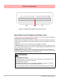
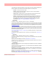
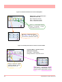
Recorder Functionality
• Minitrend QX and Multitrend SX recorders provide flexible electronic data acquisition and recording in a high functionality instrument. Minitrend QX is a DIN standard
144mm format recorder with a 5.5” QVGA display and the Multitrend SX is a large 12.1”
diagonal display format recorder.
• The Minitrend QX has up to 16 Analogue inputs and the Multitrend SX has up to 48
Analogue inputs. Both with at least 70Mb of available on-board memory plus additional
removable storage media.
• Both recorders use digital colour TFT LCD screens to provide easy to read displays with
wide viewing angles for the best all around data viewing.
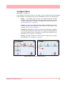
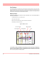
• The touch screen operator interface provides fast, easy access to the recorder menus making set up and data analysis quick and efficient. Navigation through the menus and text
entry are direct and intuitive.
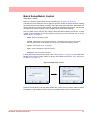
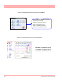
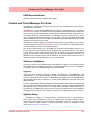
Example of a recorder menu path from the Main Menu to change the Pen Scale configuration with clear rapid navigation
43-TV-25-30 Iss.2 GLO June 06 UK
27
Functions and Features
Features
Display
• 5.5” Colour Active TFT for the Minitrend QX and 12.1” Colour Active TFT for the
Multitrend SX - with more than 256,000 colours makes it easy to interpret process data
and take action with the intuitive bar charts, digital values, trends or customised displays. A
screen saver function can be set from 1 to 720 minutes to extend the life of the backlight.
• Touch Screen - the heavy duty durable touch screen provides easy data entry and rapid
navigation though the menus.
• Help Files - A complete contextual help system can be accessed and visualised on the
screen of the recorder.
Communications
• Ethernet Connectivity - the Ethernet (DHCP standard) connection, with support for various protocols, provides comprehensive connectivity to local area networks (LANs). The
standard Ethernet interface makes networking of the recorder to a LAN or the world wide
web fast and convenient. Dynamic Host Configuration Protocol (DHCP) automatically
acquires the settings (IP address) for network communications from a DHCP server.
• RS485 Modbus - the RS485 connection allows process data to be transferred to other
devices, or to record data received in MODBUS RTU protocol (slave mode only).
• Simple Network Time Protocol (SNTP) - The recorder can be synchronised over the ethernet network via a SNTP client or synchronise other recorders via a Server.
• Web Server - with the recorder connected to a LAN, all process variables, alarm and messages can be viewed from an internet browser with automatic refresh.
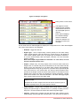
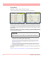
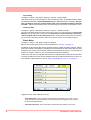
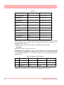
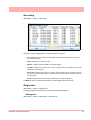
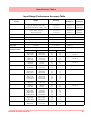
Data Storage
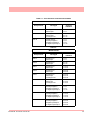
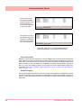
Internal Data Storage - At least 70MB expandible internal non-volatile flash memory is
available for data storage and chart history (replay of data on the display).
Internal memory / Logging rate = 1 sec
Type
Pens
70MB
180MB
400MB
890MB
1850MB
QX
8
24days
61d
137d
301d
622d
QX, SX
16
12d
30.5d
68.5d
150d
311d
QX, SX
32
6d
15d
34d
75d
155d
SX
48
4
10d
22d
50d
103d
SX
96
2
5d
11d
25d
51d
Data Export - Removable compact flash and USB flash storage device provides multiple data storage
alternatives. Data is stored in a secure binary encrypted format, with the recorder’s configurations, providing added security of the data files.
Removable Compact flash and
USB flash storage devices
28
43-TV-25-30 Iss.2 GLO June 06 UK
Functions and Features
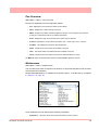
External USB Devices
• The recorder has two USB host ports, one front and one at the rear, for attaching external
USB devices such as a keyboard, mouse or a USB data storage key. The keyboard and
mouse can be used to navigate the recorder’s screen along with text entry.
Remote Viewer
• This is a firmware option that extends the user interface of the recorder onto the desktop
PC. Providing remote viewing of the unit launched from a web browser software. Full
remote control is available as an option. This function is password protected to prevent
unauthorized access. Compatible with Microsoft™ Internet explorer 6 and higher.
Security
• Total Data Integrity - data is stored in secure encrypted files making it easy to retrieve the
data dependent on process information. Data is automatically recognised without having to
remember file names.
• Password Protection - Up to 4 levels of password protection with up to 50 different users
are available. Multiple levels of password protection and an audit trail of actions enhance
the security of the data.
• Extended Security System (option) - ESS provides features including entry of unique
User ID’s and associated passwords, time-out of password entry, password expiration, and
traceability of user actions. ESS is compatible with the requirements of 21CFR part 11.
Events
Events is a firmware option that can be activated using the credit system. Events are certain
conditions or operations which can be set up and logged according to the time and date of
the occurrence. Subsequently events can be reviewed in a list or represented on a graph.
An Event is made up from a Cause and an Effect. For example, set up a cause such as Pen
1 going into an alarm state and the effect of this could be to start a totaliser or acknowledge
the alarm.
Batch
The Batch function allows the user to segment portions of data for further analysis. Batch
enhances the management of data collected in a non-continuous process, known as batch
processing, used in thermal treatment, sterilisation, food processing and chemical reactions.
Batches are controlled with command lines entered into the recorder, these include Start,
Stop, Pause, Resume and Abort batch. Batch Markers are placed on to the recorder’s chart
and entered into the messages system for every batch command applied.
Other Standard features ..
• CE Mark - Conformity with 73/23/EEC, Low Voltage and 89/336/EEC EMC Directive.
• Soft Alarms - 6 "software" alarms per pen are easily set up to display and record selected
out-of-limit conditions. These can be tied to the relay or digital outputs to activate the user’s
external equipment.
• Common Relay Output - A separate relay output at the rear of the unit can be set up as an
alarm output.
• Communications - the recorder supports Modbus TCP/IP (slave mode), web and e-mail
over Ethernet (DHCP standard) communications port and Modbus RTU (slave mode) via an
RS485 port. USB ports allow the use of an ASCII barcode reader.
43-TV-25-30 Iss.2 GLO June 06 UK
29
Functions and Features
• Independent Display Chart Speeds and Logging rates - logging rates can be programmed completely separate from the chart display speed, allowing the data to be displayed and stored at the rates that best suit the application.
• Language Support - standard language prompts for English UK & US, French, German,
Italian, Portuguese (Braz), Polish, Slovakian and Turkish.
• Logarithmic Scales - all displayed scales can be set as linear or logarithmic. max 99
decades
• Enclosure rating - standard NEMA 3 / IP55 type front face protection. NEMA 4X / IP66
available as an option.
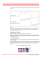
• Fuzzy Logging - this standard feature provides a unique method to increase the storage
capacity of the recorder. The data is monitored to determine changes in process data; if no
changes are observed data is logged periodically. If data is changing rapidly, it is recorded
normally at the programmed rate. By not logging data that is static, data compression of up
to 100:1 or more can be achieved saving valuable memory.
• Security tag - “wire seal provision” provides added security to seal the front door and rear
when using optional rear cover to prevent undetected entry to these areas of the recorder.
• USB Ports - Front and rear USB host ports for data and setup transfers or remote screen
through these ports. Attach external devices (keyboard or mouse).
• Replay with Zoom - Select replay mode and zoom-in on a specific area on the screen. The
data can easily be replayed at the recorder with the ability to “zoom”. The touch screen
makes it fast to review and analyse historical data.
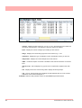
Options - Hardware
• Alarm & Digital IO Cards - 4 or 8 outputs relay contacts SPCO 240V, 8 I/O or 16 I/O SPNO 24VDC. Programmable alarm set points can be configured to activate up to 16 outputs for the Minitrend QX and 48 outputs for the Multitrend SX.
• Analogue Output - 2 or 4 outputs available per card for the Minitrend QX with 2, 4, 6 or
8 outputs available for the Multitrend SX recorder. Output type: 0-20mA or 4-20mA.
• Nema 4X / IP66 - Nema 4X / IP66 protection available as an option.
• Portable Recorders - Portable cases available as an accessory item.
• Digital Input - a number of digital input options are available. The digital inputs allow users
to initiate, from a remote location through a dry contact closure, selected recorder functions.
• Pulse Frequency - four frequency inputs per board, are available to measure pulse signals
up to 25 kHz (max. 2 cards).
• Approvals - CSA, UL and FM CL1 Div 2 approvals.
• 24VAC/DC or 48VDC Power Supply - 20 to 55VDC / 20 to 30VAC.
• 24VDC Transmitter Power Supply - Minitrend QX can supply up to 200mA to external
transmitters, up to 4 loops (not DC version), Multitrend SX up to 1A (not DC version).
• Print Support - Enables the printer option to print from various screens using a basic USB
standard PCL (Printer Control Language) printer.
30
43-TV-25-30 Iss.2 GLO June 06 UK
Functions and Features
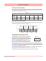
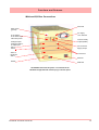
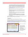
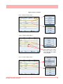
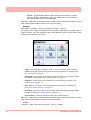
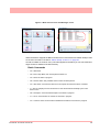
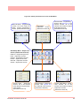
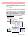
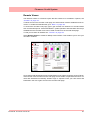
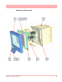
Multitrend SX Standard Screens
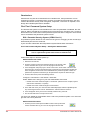
The Multitrend SX recorder has up to 30 screens displaying multiple combinations of charts, bars
and DPMs can be configured, 4 examples below.
16 Digital Panel Meters
showing Max/Min values and
Totals for each pen
DPM and Scales
43-TV-25-30 Iss.2 GLO June 06 UK
Horizontal Chart, 8 Vertical Bars & 8 DPMS
16 Horizontal Bars
showing Max/Min values and
Totals for each pen
31
Functions and Features
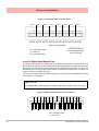
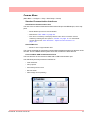
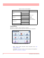
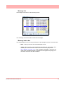
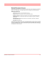
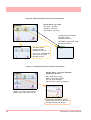
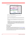
Minitrend QX Standard Screens
The Minitrend QX recorder has up to 20 screens displaying multiple combinations of charts, bars
and DPMs can be configured, 6 examples below.
32
Horizontal Chart and DPMs
Horizontal Chart, 4 Vertical Bars
and 4 DPMs
8 Digital Panel Meters
8 Horizontal Bars
DPMs and Scales
Vertical Chart, 8 Horizontal Bars
and 8 DPMs
43-TV-25-30 Iss.2 GLO June 06 UK
Functions and Features
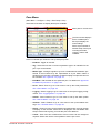
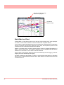
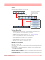
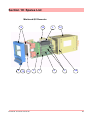
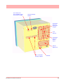
Minitrend QX Rear Connections
Wire seal
Earth screw
(ground)
AC supply
100 - 250VAC
20 to 50VDC/
20 to 30VAC Input
Instrument power
Common Relay
Output (SPNC)
Analogue Input /
Analogue Output /
or Pulse Input
Slot A
Slot B
24V TX Power
Supply Output
Alarm or
Digital I/O
Slot G
CJC Sensor
Ethernet
RS485
USB Host
100-250VAC Rear Panel AC power is connected via the
standard configuration IEC chassis plug on the rear panel
43-TV-25-30 Iss.2 GLO June 06 UK
33
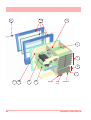
Functions and Features
Multitrend SX Rear Connections
AC supply
100 - 250VAC
Wire seal
Analogue Input /
Pulse Input
Slot A
Slot B
Slot C
Slot D
Earth screw
(ground)
20 to 50VDC /
20 to 30VAC
Input Instrument
power
Analogue Input /
Pulse Input
Analogue Output
Slot E
Slot F
Common Relay
Output (SPNC)
Alarm or
Digital I/O
Slot G
Slot H
Slot I
24V TX Power
Supply Output
CJC Sensor
Slots A to F
Ethernet
USB Host
RS485
100-250VAC Rear Panel AC power is connected via the standard
configuration IEC chassis plug on the rear panel
34
43-TV-25-30 Iss.2 GLO June 06 UK
Section 4: Recorder Setup
Configuration of the recorder is performed in the Menu screens and the data is displayed in
the Process screens. This section takes you through the Menu system and how to set up
your recorder. See “Section 6: Screen Configuration” on page 119 for information on
setting up screens to display the data.
User Interface Control
All user actions can be performed via the touch screen using the stylus. All on-screen selection and navigation areas are large enough so the unit can be operated without falsely selecting an adjacent option using the stylus provided.
The stylus is to be used to operate the touch screen. It has a rounded end to avoid damage
to the screen. Only a light touch is required to activate the screen. Two styluses are provided
and there is a special slot at the top of the recorder to slide the stylus in from the right.
Other User Interface Control
All user actions can be performed using a mouse or keyboard attached to the front or back
USB host port.
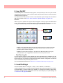
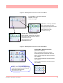
Power up
1. Menu Access
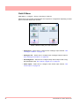
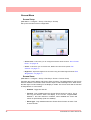
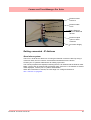
When the recorder is powered up the display will show a splash screen followed by an initialisation screen displaying the default language flag.
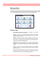
The first screen to appear on the recorder is a default process screen with the menu bar at
the top. Select the Menu button to access the menu system to configure the recorder. The
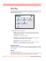
Menu button takes you to the Main Menu.
From the Main Menu you may be required to Log In, if the Password function is active, see
“2. Log On/Off” on page 36.
The next configuration required is to set the recorder to the correct local settings, see “3.
Local Settings” on page 36.
Figure 4.1 Default process screen
Access to
Main Menu
43-TV-25-30 Iss.2 GLO June 06 UK
35
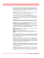
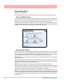
2. Log On/Off
If Password (ESS - Extended Security System, 21CFR) security is active on your recorder
a password is required to enter the menu system and process screens. Limited access is
available without logging on.
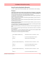
For ESS recorders only, locate the First Time Password System Setup sheet included in
with your recorder or see “First Time’ Password System Setup” on page 106.
All Users
When Log On is required the Log On button will appear in the top right of the Main Menu
screen. The Log On button can be set to switch to auto Log Off at a specified period of time.
To Log On select the Log On button at the top right of the Main Menu screen.
Log On Button
Log Off Button
• Log On - User is presented with a user name and password entry box. First time user login
is “Admin”. No password is required. Access for the first time user is removed once the
password system has been configured.
• Log Off - Once the user has logged on, the option in the Main Menu will turn to Log Off,
once selected the user is logged off and returned to the current process screen.
First Time Log On
The first time the system is used a default user name and password is available, the user
name is “Admin” and will have no password, this is known as the “first time” user. Access to
the first time user is removed once the password system has been configured. The first time
user is reinstated if the password system is reset.
For more detailed information see “Section 5: Password Security” on page 105.
3. Local Settings
Go from the Main Menu to Configure > Setup > Edit > General > Localisation
All text is displayed in the currently selected language. Help system language can be selected independently, currently English only available. To configure local settings, languages,
time zones, daylight saving, temperature units and mains frequency for input filtering, see
“Localisation” on page 69 section.
36
43-TV-25-30 Iss.2 GLO June 06 UK
Default Time Zone
Go from the Main Menu to Configure > Setup > Edit > General > Localisation > Time Zone
The recorder is set to the default Time Zone for Eastern Time (US, Canada), (GMT -5.00).
When the configuration is complete select the Finish button to Commit.
4. Time and Date Settings
Go from the Main Menu to Configure > Settings > Set Time
Set the Recorder Time and Date settings, see “Set Time” on page 83.
When the configuration is complete select the Finish button to Commit.
5. Firmware Options
Go from the Main Menu to Configure > Setup > Edit > General > Factory > Credits
Check your recorder has been set up with the correct amount of credits, displayed as a
number against the Credits item in the menu. Then select the Options item in the Credits
menu and enable the firmware options you require by changing the cross to a tick/check
symbol.
When the configuration is complete select the Finish button to Commit, Discard or Commit
Later. Select the Back button to return to the previous menu.
Menu Path
As each button is selected in the menu system a menu path will appear at the top of the
screen to enable the user to know where they are in the system. The user can select these
buttons to return to previous menus and enables the user to jump back more than one menu
at a time.
Menu path.
Select to go back
to previous menus
A grey arrows indicates
a further sub menu
Help
Help is available on all menu screens and is context sensitive from each screen. The Help
icon will reside either in the top right or bottom right on all menu screens. All the Help files
have a Home button that will take you to the Help System main index. Navigating in the help
does not stop the logging.
43-TV-25-30 Iss.2 GLO June 06 UK
37
Main Menu
Select a button
to take you to
the next menu
• Configure - Configure the recorder through the Setup, Layout and Passwords menus. See “Configure Menu” on page 39
• Alarms - Displays the current alarm status. Alarm configuration and their
associated condition. See “Alarms Menu” on page 85
• Screen - The Screen Menu an Edit button to configure Pen/Channel mapping, Replay previous data, Screen List to change the screen currently
being displayed and Clean Screen facility. See “Screen Menu” on
page 86
• Batch - The Batch function manages sections of data. Batch markers are
configured by the user and are used to identify and analyse batches of
data. See “Batch Setup/Batch Control” on page 87
• Recording - Display the current recording status of the unit and allows
recording control. See “Recording Menu” on page 90
• Messages - Displays all or specified message types. See “Messages
Menu” on page 92
• Process - Controls for any process in use eg. Max/Mins or Totals can be
controlled from this screen See “Process Menu” on page 95
• Status - Displays status information screens that are available to the user,
these will provide information for reporting and diagnostic purposes. See
“Status Menu” on page 96
• Finish - When an operation is complete use the Finish button to Commit,
Discard or Commit Later. See “Finish” on page 104
• Help - The Help icon appears as a question mark on all menu screens. The
Help files are context sensitive and will supply information for each menu
screen where the icon appears. See “Help” on page 37
38
43-TV-25-30 Iss.2 GLO June 06 UK
Configure Menu
(Main Menu > Configure >)
The Configure screen gives access to the Setup, Layout, Password menus and Settings
(Time and Date). The majority of the recorder configuration is done in the Setup menus.
• Setup - In the Setup menu the user can configure how the recorder
acquires, stores and actions data. The Edit Setup gives access to submenus for Field IO, Pens, Comms, Recording and for General recorder set
up. See “Edit Setup” on page 41
• Layout - The user can configure how the data is presented on the screen.
From the Layouts screen choose to Edit, Saved or Load layouts in the
recorder. See “Layout” on page 78
• Passwords - Manages the security and access to full password configuration that allows restricted access within the recorder, providing password
protection at different levels. Administrate, Load and Save passwords from
this menu. See “Passwords” on page 80
• Settings - Recorder settings such as Set Time to configure the recorder's
time and date. See “Settings” on page 83.
Select a button to take you to the next menu
43-TV-25-30 Iss.2 GLO June 06 UK
39
Setup Menu
(Main Menu > Configure > Setup)
In the Setup menu the user can configure how the recorder acquires, stores and actions data. The Setup screen gives access to the Edit menu where the majority of the recorder configuration is done, also Save and Load setups from this screen.
Edit Setup
(Main Menu > Configure > Setup > Edit Setup)
The Edit Setup gives access to sub-menus for Field IO, Pens, Comms, Recording and for
General recorder set up. See “Edit Setup” on page 41.
Save Setup
(Main Menu > Configure > Setup > Save)
The Save button will produce a list of destinations to save the set up to.
The Compact Flash and the front USB device port are found under the front flap on the recorder. There is another USB port at the rear of the recorder. The first USB device fitted will
be USB1, therefore the second USB device fitted is USB2.
Load Setup
(Main Menu > Configure > Setup > Layout)
Setups can be loaded from Compact Flash or USB key. The Load button will produce a list
of source files to load setups from.
The Compact Flash and the front USB device port are found under the front flap on the recorder. There is another USB port at the rear of the recorder. The first USB device fitted will
be USB1, therefore the second USB device fitted is USB2.
Back Button
Takes you back to the previous menu
40
43-TV-25-30 Iss.2 GLO June 06 UK
Edit Setup
(Main Menu > Configure > Setup > Edit Setup)
Edit Setup will access the main configuration of the recorder through further sub-menus for:
Field IO, Pens, Comms, Events, General and Screen recorder set up.
The Edit button may display a warning message if the Commit Later option has been selected This means changes to the configuration have been made but the changes have not
been committed to the recorder. See “Commit Later” on page 104.
Select a button to take you to the next menu
• Field IO - This button displays a sub menu containing Analogue In, Analogue Out, Alarm/Digital IO and Pulse Inputs card menus. See “Field IO
Menu” on page 42
• Pens - This button displays all the configuration areas for setting up Pens
including Scales, Maths, Alarms, Logging and Totalisers. See “Pens
Menu” on page 51
• Comms - This button displays a sub menu containing Protocols, Web,
SNTP and TCP/IP menus. See “Comms Menu” on page 61
• Events - Events is a firmware option that can be activated using the credit
system. Events are certain conditions or operations which can be set up
and logged according to the time and date of the occurrence. Subsequently
events can be reviewed in a list or represented on a graph. See “Events
Menu” on page 66.
• General - This button displays a sub menu containing general recorder
information including Ident, Localisation, Factory, Batch, Printer set up and
Groups (Pens) menus. See “General Menu” on page 68
• Screen - This button displays a sub menu containing Screen Saver, Chart
speed and screen Brightness set up. See “Screen Setup” on page 76
43-TV-25-30 Iss.2 GLO June 06 UK
41
Field IO Menu
(Main Menu > Configure > Setup > Edit Setup> Field IO)
Select which type of Field Inputs/Outputs are required for configuration depending on what
type of cards are fitted in the recorder.
Select a button to take you to the next menu
• Analogue In - Select this to configure each Analogue Input channel. See
“Analogue In Menu” on page 44
• Analogue Out - Select this to configure each Analogue Output channel.
See “Analogue Out Menu” on page 46
• Alarm/Digital IO - Select this to configure Relay Alarm Output card or Digital Input/Output card. See “Alarm / Digital IO” on page 47
• Pulse Inputs - Select this to configure each Pulse Input channel. See
“Pulse Input” on page 49
42
43-TV-25-30 Iss.2 GLO June 06 UK
Table 4.1 : Card Positions and Channel Numbers
Minitrend QX
Slot position
Card type
Channel
numbers
Slot A
8 Analogue In
Pulse Inputs
1 to 8
1 to 4
Slot B
8 Analogue In
Pulse Inputs
4 Analogue Out
9 to 16
9 to 12
9 to 12
Slot G
4 Relay Output
8 Relay/2 Digital In
8 Digital Input/Output
16 Digital Input/Output
1 to 4
1 to 8
1 to 8
1 to 16
Table 4.2 :
Multitrend SX
Slot position
43-TV-25-30 Iss.2 GLO June 06 UK
Card type
Channel
numbers
Slot A
8 Analogue In
Pulse Input
1 to 8
1 to 4
Slot B
8 Analogue In
Pulse Input
9 to 16
9 to 12
Slot C
8 Analogue In
Pulse Input
17 to 24
17 to 20
Slot D
8 Analogue In
Pulse Input
25 to 32
25 to 28
Slot E
8 Analogue In
Pulse Input
4 Analogue Out
33 to 40
33 to 36
33 to 36
Slot F
8 Analogue In
Pulse Input
4 Analogue Out
41 to 48
41 to 44
41 to 44
Slot G
4 Relay Output
8 Relay/2 Digital In
8 Digital Input/Output
16 Digital Input/Output
1 to 4
1 to 8
1 to 8
1 to 16
Slot H
4 Relay Output
8 Relay/2 Digital In
8 Digital Input/Output
16 Digital Input/Output
17 to 20
17 to 24
17 to 24
17 to 32
Slot I
4 Relay Output
8 Relay/2 Digital In
8 Digital Input/Output
16 Digital Input/Output
33 to 36
33 to 40
33 to 40
33 to 48
43
Analogue In Menu
(Main Menu > Configure > Setup > Edit Setup> Field IO > Analogue In)
Press the Analogue In button to display all the analogue inputs available.
Click on individual Analogue In number to set up each channel profile. Each channel has a
list of menu items to be configured.
Refer to connection details and “Analogue Input Channel Numbers” on page 15.
.
Menu path to current menu
The Analogue In screen
displays all the available
Analogue Input channels.
Each channel displays its’
individual settings.
Select a numbered channel
to edit the configuration of
each input
• Enabled - Toggle On and Off.
• Type - Select this for a list of available Signal Inputs.
• Sample Rate - Select this for a list of available Analogue Input sample
speeds. A Fast Scanning range of 50Hz (20ms) is available as a firmware
option. See “Firmware Credit System” on page 129.
• Range (Ohms, Volts and Amps only) - Toggle between Preset and User
Defined. The Preset option will make available a list of Range Types or
select User Defined to specify High and Lower Limits.
• Range Type (Ohms, Volts and Amps only) - Only available when Range is
set to Preset. Select for a list of available ranges. The factory default range
is +/-12V. See “User Defined Maximum Input Ranges” on page 170
• Voltage Units (Volts only) - Select Volts or Millivolts.
• High Limit - Available when Range is User Defined. Select and enter the
high limit value.
• Lower Limit - Available when Range is User Defined. Select and enter the
lower limit value.
• RT Type - Only available when Type is set to RT (Resistance Thermometer). Select this for a list of available RT types.
44
43-TV-25-30 Iss.2 GLO June 06 UK
• Burnout Type - Only available when Type is set to TC (Thermocouple).
Toggle between Active and Passive. Active means it will send out a current
to the TC. Set to Passive means it takes a reading without sending out a
current. The T/C is wired differently for Active an Passive Burnout (see
Figure 2.6, “Input signal wiring,” on page 16).
• Show Burnout - Only available when Type is set to TC. Toggle between
Upscale and Downscale Burnout.
• TC Type - Only available when Type is set to TC. Select this for a list of
available TC types.
• CJ Comp - Only available when Type is set to TC. Select this for a list of
available CJ Compensation.
• • Int Automatic - Uses the cold junction sensor in the recorder as a variable reference temperature
• • Ext 0 Deg C - Assumes the cold junction is held at 0°C to provide a 0mV reference, external to the recorder
• • Ext with Spec Temp - Uses a reference junction held at a constant temperature. Specify the temperature that the cold junction sensor is to be set at.
• • Ext Input - Use a thermocouple or resistance thermometer from another channel to measure the cold junction sensor
• External Input - Only available when CJ Compensation is set to Ext Input.
Select the input required as an external input.
• Use Pen Scale - Toggle On and Off, this is enabled by default. Analogue #
defaults to the corresponding Pen #, eg. A1 will default to Pen 1. If you
change A1 to display another pen scale eg.Pen 3, you must go into Pen 3
and change the maths to A1. This will ensure that Pen Scale 3 will display
A1 input. With this enabled the Engineering zero and span is the same as
the pen scale. Disable this and the Engineering zero and span will not
reflect the pen scale.
• Eng. Span - (Ohms, Volts and Amps only). Only available when not using
“Use Pen Scale” option. This is the highest value of the engineering range
and corresponds to the top of the input range. Select and enter a value
using the on-screen keyboard.
• Eng. Zero - (Ohms, Volts and Amps only). Only available when not using
“Use Pen Scale” option. This is the bottom of the engineering scale and
represents the bottom of the input scale. Select and enter a value using the
on-screen keyboard.
• Units - (Ohms, Volts and Amps only). This is the Units of Measurement for
each input. Select and enter a value. Max 13 characters. For Thermocouple
and Resistance Thermometer units, see “Localisation” on page 69.
• Label - Select and enter a identification label for the input. Select and enter
a label. Max 15 characters.
43-TV-25-30 Iss.2 GLO June 06 UK
45
• SQRT Extract - (Ohms, Volts and Amps only). Toggle On and Off. The
square root extraction in the analogue input is used to linearise a non-linear
input.
• Sensor Comp - Sensor Compensation may be required to improve accuracy on a sub range. This is an adjustment to the value of the signal input
on each channel, based on the Engineering units settings. See “Sensor
Compensation” on page 211
• Demo Setup - Only available if there is no Analogue Input card fitted.
Examples of various inputs are available without having an actual signal
input coming into the recorder.
• • Demo Type - Select this for a list of available Demo Type inputs.
• • Cycle Time - Enter the Cycle Time, in seconds, of the Demo Input. Select and
use the on-screen keyboard.
• • Add Noise - This is to Add Noise to the Demo Input as a percentage value.
Select and use the on-screen keyboard.
When the configuration is complete select the Finish button to Commit, Discard or Commit
Later. Select the Back button to return to the previous menu.
Analogue Out Menu
(Main Menu > Configure > Setup > Edit Setup> Field IO > Analogue Out)
Only available when an Analogue Out card is fitted as an option, 2 or 4 outputs are available
per card.
Refer to connection details and “Analogue Output Channel Numbers” on page 17
Menu path to current menu
The Analogue Out screen
displays all the available
Analogue Output channels.
Each channel displays its
individual settings.
Select a numbered channel
to edit the configuration of
each output
Press the Analogue Out button to display all the analogue outputs available. Click on individual Analogue Out number to set up each channel profile.
• Enabled - Toggle On and Off.
46
43-TV-25-30 Iss.2 GLO June 06 UK
• Allow Overrange - Toggle On and Off. Disabled as default, this will allow
the output signal to go overrange to 21mA, if disabled the maximum is
20mA.
• Transmit Pen - Eg. Select a pen to output 4-20 mA loop. This will take the
scale value from the pen it is transmitting and convert to 4-20mA output signal. eg if the scale is 0-50% this signal will fit the scale so 4mA = 0% and
20mA = 50%. For 0-20mA output signal with the same 0-50% scale, this
would read 0mA = 0% and 20mA = 50%.
• Output - Select either 4-20mA or 0-20mA.
• Label - Select and enter an identification label. Select and use the onscreen keyboard. Up to 16 characters.
When the configuration is complete select the Finish button to Commit, Discard or Commit
Later. Select the Back button to return to the previous menu.
Alarm / Digital IO
(Main Menu > Configure > Setup > Edit Setup> Field IO > Alarm/Digital IO)
The Alarm/Digital IO button will display all the digital inputs/outputs available. Click on each
individual Alarm IO or Digital IO number to set up each channel profile.
Cards available are:
2 types of Alarm Relay cards
• 4 Alarm Relay Output
• 8 Alarm Relay Output with 2 Digital Inputs
2 types of Digital IO cards
• 8 Digital Inputs or Outputs
• 16 Digital Inputs or Outputs
Alarm Relay Card
4 Alarm relay output card or 8 Alarm relay Output with 2 Digital Inputs (6 fixed outputs and
2 configurable Digital Input or output) cards.
Digital IO Card
There are 8 or 16 Digital channels per card that can be setup as inputs or outputs. The Digital I/O card also has 4 channels that can be set as pulse inputs (channels 1 to 4). The operating frequency for pulse inputs on the Digital I/O card is 1kHz max.
To view and log a channel selected as a Pulse input, set up an extra pen with a Maths function of LPULn in Edit Maths in the Pens menu. For more information see “Appendix B:
Maths Expressions” on page 183.
For connection details see For connection details See “Alarm Relay Channel Numbers”
on page 21
43-TV-25-30 Iss.2 GLO June 06 UK
47
Figure 4.2 Example of Digital IO
Menu path to current menu
The Digital IO screen
displays all the available
channels that can be set
up to be digital inputs or
outputs.
Each channel displays
its individual settings.
Select a numbered
channel to edit the configuration of each input
or output.
For all cards select an Alarm/Digital # to display the configuration menu. Each Alarm/Digital
has a list of menu items to be configured.
• Enabled - Toggle On and Off
• Digital Type - Set to Output Relay contact (Power) for the Alarm Relay
cards. Toggle between Input and Output or Pulse Input for the Digital IO
card. On the 4 Relay Alarm card, only output type is available. Channels 1
to 6 on the 8 Alarm Relay card are outputs, channels 7 & 8 can be either
inputs or outputs.
Note: Pulse Input only available on channels 1 to 4 for slot G, 17 to 20
for slot H and 33 to 36 for slot I.
• Output - (Output only). The relay outputs can be set to be either Latched or
Single Pulse. A Latched relay will be maintained in its active state until the
trigger source has returned to a non-alarm state (unless acknowledged).
For Single Pulse the relay will go active for a period of time, specified by the
user, then return to a non active state. The time out period remains independent of the length of time the active state remains. If the output is set to
Single Pulse, when the alarm is activated the signal will display a single
pulse for the duration set. See Pulse Duration. The alarm will trigger again
when it goes back into an active alarm state.
NOTICE
Outputs that are set to Single Pulse should not be used as a part of
a maths expression as it can cause spurious values.
• Pulse Duration - (Output only). Available when Single Pulse is selected.
Specify the pulse length in seconds from 0.1 (100ms) to 6480 (108 minutes) in 0.1 second increments. Select and enter the pulse length.
• Failsafe - (Output only). Toggles On and Off. Each relay channel can be
independently selected with the fail safe option. This will invert the state of
48
43-TV-25-30 Iss.2 GLO June 06 UK
the relay output. With Failsafe Off, normally open (NO) relays have open
contacts when the power is off, and open contacts when there is no active
alarm. The contacts will close when an associated alarm goes active. With
Failsafe On, normally open relays have closed contacts when the recorder
is powered on and there are no open active alarms, and the contacts open
with an alarm active or when the power is removed. See “Failsafe Relay
Positions” on page 172.
• Label - Select and enter an identification label. Up to 16 characters.
• Active Label - (Input and Output only). This is the label that is shown when
an alarm becomes active. Select and enter a label. Not available for Pulse
Input. Up to 12 characters.
• Inactive Label - (Input and Output only). This is the label that is shown
when an alarm becomes inactive. Select and enter a label. Not available for
Pulse Input. Up to 12 characters.
• Report - This will acknowledge the Alarm/Digital IO to a selected destination. Select User message to add the Digital IO occurance to the messages
list only. Select Mark On Chart to display the occurance on a chart and to
the messages list.
When the configuration is complete select the Finish button to Commit, Discard or Commit
Later. Select the Back button to return to the previous menu.
Pulse Input
(Main Menu > Configure > Setup > Edit Setup> Field IO > Pulse Input)
Only available when a Pulse Input card is fitted as an option. The Pulse Input card operates
up to a frequency of 25kHz max. See “Pulse Input Channel Numbers” on page 19.
If a Pulse input card is fitted in slot A the first 4 pens will display the maths function of HPULn
in Edit Maths in the Pens menu as default to display the pulse reading. For more information
see “Appendix B: Maths Expressions” on page 183.
Menu path to current menu
The Pulse Input screen
displays all the available
pulse input channels that
can be set up.
Each channel displays its
individual settings.
Select a numbered channel
to edit the configuration of
each Pulse input.
Press the Pulse Input button to display the available pulse inputs.
43-TV-25-30 Iss.2 GLO June 06 UK
49
Click on individual Pulse Input number to set up each channel profile.
• Enabled - Toggle On and Off.
• Hertz - Fixed as Frequency Measure (in Hertz).
• Update Rate - Fixed at 1Hz
• Label - Select and enter an identification label for the pulse input. Select
and enter a label. Up to 16 characters.
When the configuration is complete select the Finish button to Commit, Discard or Commit
Later. Select the Back button to return to the previous menu.
50
43-TV-25-30 Iss.2 GLO June 06 UK
Pens Menu
(Main Menu > Configure > Setup > Edit Setup> Pens)
Select the Pens button to display all the pens available.
Menu path to current menu
The Pens screen displays
all the available pens.
Each pen displays its
scale settings.
Select a pen number to
edit the setup of each pen
including the Scale,
Logging, Alarms and
Totaliser
Click on individual pen number to set up each pen profile.
• Enabled - Toggle On and Off.
• Tag - Select and use the on-screen keyboard to type in an identifier for the
pen. Up to 48 characters.
• Maths Type - Analogue signals may have a mathematical calculation performed on them before they are represented as a pen. Basic maths is
standard in all recorders. Full Maths or Math Scripting are options that must
be activated. See “Options” on page 97
• Edit Math - Edit the Math for this particular pen. For details see “Appendix
B: Maths Expressions” on page 183.
• Scale - Select Scale to go to a sub menu to set up the scale parameters.
See “Scale Menu” on page 52
• Logging - Select Logging to go to a sub menu to set up the logging configuration. See “Logging Menu” on page 53
• Alarms - Select Alarms to go to a sub menu to set up the alarm profile.
See “Alarms Menu” on page 55
• Totaliser - Select Totaliser to go to a sub menu to set up the totaliser settings. See “Totaliser Menu” on page 57
• Group - Groups of pens can be specified and tagged with a group number
to display on the recorder. Select this to display the list of available Pen
Groups. Select which group you want this pen to be added to.
• Colour - Each Pen has a Default Pen Colour but this can be changed if
required. Select and use the colour palette to set the pen colour.
43-TV-25-30 Iss.2 GLO June 06 UK
51
• Trace Width - Select and set the Trace Width for this pen when it is displayed on a chart. The default trace width is 1 with a maximum of 7.
When the configuration is complete select the Finish button to Commit, Discard or Commit
Later. Select the Back button to return to the previous menu.
Scale Menu
(Main Menu > Configure > Setup > Edit Setup> Pens > Scale)
Individually configure each scale per pen in the scale menu.
Menu path to current menu
Select the Scale button to take you to the Scale menu
Click on Scale to set up each scale profile per pen.
• Units - Scale measurement Units. Select this and enter the units. Up to 16
characters.
• Span - This is the highest value of the scale. Select to enter the Span
value.
• Zero - This is the bottom of the scale. Select to enter the Zero value.
• Scale Type - Toggle between Linear or Logarithmic (Log).
• Divs Select - Only available with Linear Scale Type. Toggle between Auto
or User Defined.
• Major Divs - Only available when Divs Select is set to User Defined. Select
and enter the major division position.
• Minor Divs - Only available when Divs Select is set to User Defined. Select
and enter the minor division position.
• Start Decade - Only available when the Scale Type is set to Log. Select
and enter the start value of the first decade.
52
43-TV-25-30 Iss.2 GLO June 06 UK
• No. Decades - Only available when the Scale Type is set to Log. Select
and enter the number of decades required. Max 99 decades.
• Numb Format - Displays the Notation of the number format, Scientific or
Normal.
• • Notation - Toggle between Scientific or
Normal number format. The scientific
fomat displays the value to the power of 10
shown here. Notice the value has been
rounded up..
Normal
Scientific
• • Auto - Toggle Between Automatic number
formatting and User Defined.
• • After Decimal - Only available when User Defined is selected. Select and
enter the number of decimal places. (up to 15 decimal places)
When this pen setup is complete go back to the Pen # menu and complete the pen setup
for all other pens.
Logging Menu
(Main Menu > Configure > Setup > Edit Setup> Pens > Logging)
Menu path to current menu
Pen Logging can be set to log as Continuous or Fuzzy
Click on Logging to set up each logging profile per pen.
• Enabled - Toggles On and Off to activate or de-activate logging for this
pen.
• Type - Toggles between Continuous or Fuzzy logging.
Continuous logs every value based on the Method chosen (Sample, Average or Max/Min).
Fuzzy Logging has been developed as a secure data storage technique
43-TV-25-30 Iss.2 GLO June 06 UK
53
which has a self teaching data storage algorithm so the recorder stores
data at a variable rate to match the process being monitored. Fuzzy Logging has intelligent resources to enable the most effective and efficient way
of using the scan rate, storage capacity and recording time. See “Appendix F: Fuzzy Logging” on page 205
• Rate Units - Set the Units for the logging rate to be displayed. Select and
choose the logging rate units from the drop down menu.
• Rate - This is the speed at which data is required to be logged.
If the Millisecond option is selected as the Rate Units for the logging, then
a drop down menu of options will appear. When all other Rate Units are
selected a keypad will appear for user entry. Fastest rate is 20mS and slowest is 60 hours.
• Alarm Rate Units - Set the Units for the Alarm logging rate to be displayed.
Select and choose the alarm logging rate units from the drop down menu.
• Alarm Rate - This is the new logging rate used when this pen goes into an
active alarm state. To enable this feature to change the logging rate in an
alarm state, see Change Log in the Alarms menu.
If the Millisecond option is selected as the Alarm Rate Units for the logging, then a drop down menu of options will appear. When all other Alarm
Rate Units are selected a keypad will appear for user entry.
• Method - Only available if the logging Type is set to Continuous. Select
from a list of Methods.
Sample: logs the last sampled reading.
Average: logs the average of all the samples taken since the last log.
Max/Min: logs the highest and the lowest of the sampled readings since the
last log.
• Align - Only available if the logging Type is set to Continuous. Select and
enter a value from the list to align the logging at specified intervals. This
will hold the start of logging until the aligned time selected occurs based on
the recorders real time clock.
• Auto Fit - Only available if the logging Type is set to Fuzzy. Toggles On and
Off. AutoFit ensures that the last sampled data point is logged before the
signal goes out of the tolerance set in Band 1 or Band 2. When displayed
on a graph, the input signal will automatically fit to this last logged point.
This gives a better fit for stepped input changes.
• Band 1 % - Only available if the logging Type is set to Fuzzy. This is where
the tolerance is set for the input signal. Specify, as a percentage of the
scale range, the tolerance band allowed above and below the input signal.
Select and enter a value.
• Fuzzy Band 2 - Only available if the logging Type is set to Fuzzy. Toggles
On and Off. This is to enable a second tolerance to be set, configure it to be
On to activate. Only used in conjunction with Autofit On, to specify the Band
2 %.
54
43-TV-25-30 Iss.2 GLO June 06 UK
• Band 2 % - Only available if the logging Type is set to Fuzzy. This is where
a tighter tolerance can be specified which must be set within the limits of
Band 1. Specify, as a percentage of the scale range, the tolerance band
allowed above and below the input signal. Select and enter a value.
When the setup is complete go back to the Pen # menu and complete the pen setup.
Alarms Menu
(Main Menu > Configure > Setup > Edit Setup> Pens > Alarms)
This is for setting up alarms on this pen only. Select the first available alarm eg. Alarm 1 and
configure each alarm.
Menu path to current menu
The Pen Alarms screen displays up 6
alarm set points per pen.
Each alarm displays its individual
alarm setting.
Select an alarm number to edit the
setup of each alarm
When an alarm has been configured an Alarm Marker or Pen Pointer will appear for each
alarm depending on the type of process screen. See “Alarm Markers” on page 125
• Enabled - Select Enable to see a list of ways to enable or disable the
alarm. Disable, Enabled Always or Dig Enabled.
• Enabled by Digital - Only available when Enabled is set to Dig Enabled.
Select and choose which digital signal(s) will enable this alarm (on this pen
only).
• Type - Select this to display a list of different types of Alarms. High, Low,
Deviation. Set a High alarm to activate when the signal goes above the
Alarm Level, or set a Low alarm to activate when the signal goes below the
Alarm Level. Deviation is the how far this pen can deviate from the Ref Pen
before triggering an alarm. See Deviation Level.
• Level - Select and enter a figure at which the alarm is to be triggered.
• Deviation Level - Only available when Alarm Type is set to Deviation.
Select and use the numeric keypad to enter the amount of deviation (in
engineering units) to a designated pen (Ref Pen) before an alarm is triggered.
43-TV-25-30 Iss.2 GLO June 06 UK
55
• Ref Pen - Only available when the alarm Type is set to Deviation. Select
and enter the pen that this alarm is referenced to. This works like an actual
pen that dynamically tracks a designated pen.
• Tag - Enter a tag or name to identify this alarm. Up to 17 characters.
• Allow Change - If activated this will allow quick configuration changes to
this alarm level from the Alarms > Configure button on the Main Menu.
This does not change the original setup.
• Relays Out - Select and choose which Relay Output(s) is triggered by this
alarm (on this pen only). The Fixed button will use the common relay output
on the power board (24V relay).
• Latched - A latched alarm will maintain in its active state until the trigger
source has returned to a non-alarm state and the alarm has been acknowledged. A latched alarm will continue to flash, if an alarm marker or pen
pointer is displayed, until it is acknowledged and in a non-alarm state. Normal alarms can also be acknowledged. See “Acknowledging Alarms” on
page 201 A Reflash option is available to keep the alarm flashing whilst in
an alarm state even after it has been acknowledged. See Reflash.
• Change Log - Toggles On and Off. Select this to change the Log speed
when an alarm occurs. The Log rate changes when alarm is active and
stays at the alarm rate for as long as the alarm is active then returns to the
normal logging rate. Set up the new alarm logging rate in Alarm Rate in
“Logging Menu” on page 53.
• Mark Chart - Toggles On and Off. Selecting On will place a Mark on the
Chart with automated messages when the alarm becomes active. From the
position of the Mark on Chart the chart background colour will change to
show it is in an alarm state.
• Hysteresis - (not available for Deviation). Toggles On and Off. When this is
activated, you can set a tolerance level for an alarm. It allows a specifed
percentage value of the span of the scale to be added to the alarm level.
• Hyst Level % - (not available for Deviation alarm). Enter as a percentage
of the span of the scale. This is how much tolerance the signal can have
past the set alarm activation point until the alarm is de-activated. The example in Figure 4.3 shows the alarm activating at 40% which is the set low
alarm level. The alarm is not de-activated until the signal is at 50%, which is
10% past the set alarm level. So the Hyst Level % would be set to 10%.
Reverse the process for a high alarm.
• Damping - Toggles On and Off. Damping is a time delay that works going
into alarm only. When switched On, the alarm level must be breached for a
specific period of time before an alarm is triggered.
• Damping Time - Set the amount of Damping time in seconds
• Reflash - Toggles On and Off. Activate this to re-enable an active alarm
that has been acknowledged. Set the Reflash Time.
56
43-TV-25-30 Iss.2 GLO June 06 UK
• Reflash Time - Only enabled when Reflash is active. Set the time period
after the alarm has been acknowledged for the alarm to reflash if it is still in
an alarm state.
When the setup is complete go back to the Pen # menu and complete the pen setup.
Figure 4.3 Hysteresis Level
100%
Alarm de-activated
at this point
10% Hysteresis level
50%
40%
0%
Low Alarm Level
Alarm activated
at this point
Totaliser Menu
(Main Menu > Configure > Setup > Edit Setup> Pens > Totaliser)
The Totals option must be active to use this option. See Table 7.1, “Firmware Options,”
on page 129.
The Totaliser function is normally associated with flow monitoring applications. The input to
the recorder would be a measure of flow rate (eg. In litres per second) and the total amount
that has flowed over a specified time period. Multiple totalisations are possible with the use
of extra pens (firmware Credit option). Totalisation values are 10 digits plus exponent.
Select Totaliser from the Pen screen to display the totalising setup menu.
Totaliser menus showing Normal and Sterilisation types
Menu path to current menu
43-TV-25-30 Iss.2 GLO June 06 UK
57
Click on Totaliser to set up the totalising profile per pen.
• Enabled - Toggles On and Off to activate or de-activate totalising for this
pen.
• Type - Select this for a list of Types of totalising. Normal or Sterilisation.
Normal totaliser function is usually associated with flow monitoring applications.
Sterilisation* is where items are subjected to heat over a period of time.
Each pen can be totalised according to the Fo or Po sterilisation* function
at 250 °F (121.11°C). The Standard Reference Temperature and Thermal
Resistance (Z Value) are adjustable. All temperature limits are adjustable.
Start temp, Reference temp and Z factor are all user defined, allowing support for many different types of sterilisation applications. See “Sterilisation” on page 59
• Tag - Select and enter an identifier for the pen. Up to 17 characters.
• Add to Msgs - Toggles On and Off. Select this to add a totaliser to the
messages screen. Eg. Total1: Total 1 Reset
• Units - Normal Totaliser only. This is the Units of Measurement for the totaliser. Select and enter the units. Up to 12 characters.
• Time Factor - Normal Totaliser only. The normal totaliser units are divided
by the time factor.
• Unit Factor - Normal Totaliser only. This is the totalising factor for the conversion from pen input units to a totaliser value. The normal totaliser units
are multiplied by the unit factor.
• No Backflow - Normal Totaliser only. If the flow reading should go into a
negative value, eg. The flow meter has been switched off, and “No Backflow” is inactive, the totaliser will subtract from the total value. When “No
Backflow” is active any negative values are ignored and the total value is
held while the flow meter is off until the backflow level is exceeded.
• Backflow Level - Only active when No Backflow is set. Set the level at
which totalising will stop if the signal flow goes below this limit and if the No
Backflow option is active.
• Restrict Range - Normal Totaliser only. Toggles On and Off. When active
the totaliser restarts at Min range once it reaches Max range.
• Min. Range - Normal Totaliser only. Only available when Restrict Range is
active. Select and enter the minimum limit for the totals to range to.
• Max. Range - Normal Totaliser only. Only available when Restrict Range is
active. Select and enter the maximum limit for the totals to range from.
• Use Remainder - Normal Totaliser only. Only available when Restrict
Range is active. Toggles On and Off.
If the total exceeds the maximum range set, the total will reset to the mini-
58
43-TV-25-30 Iss.2 GLO June 06 UK
mum range set. When Use Remainder is active, it will carry over any
amount in excess of the maximum range set.
• Temp Input Units - For Sterilisation, select the temperature input units.
• Start Temp - For Sterilisation, select the Start Temperature.
• Ref. Temp - For Sterilisation, select the Reference Temperature.
• Z Factor Temp - For Sterilisation, select the Z factor temperature
• Include Cooling - For Sterilisation, Include Cooling if required
• Completion Value - For Sterilisation, if cooling is not required, enter a
Completion Value. The totaliser will stop at this value.
• Numb Format - Displays the Notation of the number format, Scientific or
Normal.
• • Notation - Toggle between Scientific or Normal number format.
• • Auto - Toggle Between Automatic number formatting and User Defined.
• After Decimal - Only available when User Defined is selected. Select and enter the
number of decimal places. (up to 15 decimal places)
When the setup is complete go back to the Pen # menu and complete the pen setup.
Sterilisation
*Specification for Sterilisation. The definition Fo/Po is the sterilisation/pasteurisation time in
minutes required to destroy a stated number of organisms with a known z at temperature T.
For example, "F18/250" represents the time in minutes required to destroy a stated number
of organisms at a temperature of 250F (121.11C) with a z = 18 degrees F. F values are used
to compare the sterilizing values of different processes, however, F values cannot be compared unless the z values are the same. When temperature is not specified (for example, F
= 8.6) it is understood that the temperature is 250F (121.11C); the subscript O (as in the
term Fo = 7.4) is used to indicate that the z = 18 degrees F and the temperature is 250F
(121.11C)
Displaying Totals
Totals can be displayed by setting up a separate pen to display the totalised value. Totals
are best displayed in a DPM screen. If you use a separate pen to display a total be aware
that if the total is stopped the pause symbol will not appear as it does for a totaliser pen.
First, select a pen you are going to use to display the total of another pen. Extra pens are
available as a Firmware option see “Credits” on page 70). For this example this will be Pen
4.
In the pens menu for the totalising pen (Pen 4), select Edit Maths and enter “T” followed by
the pen number you wish to totalise eg.T3. Pen 4 is now set to totalise the value of Pen 3.
It may be necessary to set a larger scale for the totalising pen (pen 4) as the totalising value
may become larger than the pen scale of the pen being totalised (pen 3).
When the configuration is complete select the Finish button to Commit, Discard or Commit
Later. Select the Back button to return to the previous menu.
43-TV-25-30 Iss.2 GLO June 06 UK
59
Go to the recorder’s process screen and select a screen showing DPMs. The totalising pen
(pen 4) will display the totalising value of pen 3.
60
43-TV-25-30 Iss.2 GLO June 06 UK
Comms Menu
(Main Menu > Configure > Setup > Edit Setup> Comms)
Standard Communication Interfaces
Rear Ethernet Communication Port
The rear of the recorder is fitted with an Ethernet10/100 port and RS485 port, which supports:
• RS485 Modbus protocol and TCP/IP Modbus
• Web Browser. See “Web” on page 63
• OPC Server connectivity to third party software. OPC Server connection must be
enabled by selecting the OPC option in “Credits” on page 70. For more details
on OPC Servers see “OPC Interface - Open Process Control” on
page 140
Rear RS485 Port
• RS485: 2 wire to support Modbus RTU.
This can be supported as a separate communications module that plugs into the back of the
recorder. This is a Master-Slave system where the recorders are slave devices
Front and Rear USB Communication Ports
The front and rear of the recorder is fitted with a USB communication port.
The USB Host ports will provide an interface for:
• Data downloads.
• Setup uploads.
• External keyboard & mouse
• Barcode reader
• Mass storage device (USB key)
43-TV-25-30 Iss.2 GLO June 06 UK
61
• Modbus - Modbus can be used with RS485 or Ethernet ports. See “Modbus” on page 62
• Web - Enables web access to view the recorder web page. See “Web” on
page 63
• SNTP - Simple Network Time Protocols. See “SNTP” on page 63
• TCP/IP - Transmission Control Protocol / Internet Protocol. See “TCP/IP”
on page 64
Modbus
(Main Menu > Configure > Setup > Edit Setup> Comms > Modbus)
Modbus can be used with RS485 or Ethernet ports. The Modbus protocol defines a message structure that controllers will recognise and use, regardless of the type of network over
which they can communicate.
• Enabled - Toggle On and Off
• Port - Select this for a list of available Protocols, either Ethernet or RS485.
For port configuration see “Ports” on page 65
• Protocol - Select this for a list of available ports. Modbus or Modbus X*.
Modbus and Modbus X can both use Ethernet or RS485 Ports. Protocols
define the format in which the data is transferred from the recorder to a PC
or transfer between other devices and peripherals.
• Slave ID - This is a unique Modbus ID/Address used by the recorder to
identify Modbus messages. Applications that talk to the recorder with Modbus will need to know this number to return messages to the device. If you
are using the Communication Server of Trend Server Pro the same
number must match.
• Baud Rate - (Only available when the RS485 port in selected). Select this
for a list of available Baud Rates. This is the speed, in bps (bits per second), at which data is transferred.
• Byte Options - (Only available when the RS485 port is selected). Select
this button for a list of available Byte Options. The Byte Options consist of 3
digits comprising of Parity (set to None N, Even E or Odd O), 8 Data Bits
and Stop Bits, signifying the end of the character string, 1 or 2,
• Line Turn Around - Only available when the RS485 port in selected). This
is for a 2-wire line type. Data has to be fully transmitted before the line can
be turned-around and data can be received, or vice versa.
• Reply Delay - Enter a delay time, in milli seconds, before the recorder
sends a reply. Recommended delay should be set to 12mS (min.) if using
the Comms Server.
*Modbus X - Modbus X protocol differs from standard Modbus by the 4 floating point order
that is reversed for application compatibility.
When the configuration is complete select the Finish button to Commit, Discard or Commit
Later. Select the Back button to return to the previous menu.
62
43-TV-25-30 Iss.2 GLO June 06 UK
Web
(Main Menu > Configure > Setup > Edit Setup > Comms > Web)
The Web browse function is enabled/disabled from the recorder. Select this to enable and
allow the recorder to be browsed on a web page. Internet access is required. The Web button is password protected if passwords are enabled. For web browsing information see
“Web Browser” on page 142 and “Internet Security Settings” on page 142.
“Level Permissions” on page 109 for information on permission levels to the Web Browser and access within the web page for Full Remote Control.
SNTP
(Main Menu > Configure > Setup > Edit Setup > Comms > SNTP)
Simple Network Time Protocols is a protocol for synchronising the clock on the recorder with
a Network Server.
• Server Enable - Toggle On and Off. Activate this to make this recorder the
server. Other recorders, set up as clients, can synchronise their time to this
server recorder.
• Client Enable - Toggle On and Off. Activate this to set this recorder to synchronise time with the server. See Figure 4.4 on page 64.
• Server Name - Only available when Client Enable is active. This is the
name of the Network Server that can be used for time synchronisation.
Enter the server name to be used for time synchronisation (this could be a
Time Server on the internet or on your network). If a recorder is acting as
the Server, the Client recorders must have the recorder’s name as the
Server Name (up to 32 characters). See “Ident” on page 69 for the
recorder’s name.
• Period - Only available when Client Enable is active. Select and enter the
time period in seconds required between checking and updating the time
using the on-screen keyboard. This will default to 120 seconds.
• Threshold - Only available when Client Enable is active. This is a specified
amount of time (in seconds) that the recorder clock must be within to
ensure synchronisation with the network server. Eg. if set to 3600 the
recorder time must be within 1 hour of the network server to ensure time
sync will take place.
43-TV-25-30 Iss.2 GLO June 06 UK
63
Figure 4.4 Client/Server network
Client/Server Network
Figure 4.4 on page 64 shows a Network Server at the top, a recorder acting as both a
server and a client in the middle and a string of client recorders at the bottom. A recorder
can be set up to be a server and a client. Setting it as both means this recorder will synchronise time with the network server. But will also allow other recorders to time sync with it. This
saves many recorders trying to time sync with the network server.
When the configuration is complete select the Finish button to Commit, Discard or Commit
Later. Select the Back button to return to the previous menu.
TCP/IP
(Main Menu > Configure > Setup > Edit Setup > Comms > TCP/IP)
Transmission Control Protocol/Internet Protocol.
A protocol for communication between computers, recorders and other devices.
• Static IP - Toggle On and Off. This is an IP address which is the same
every time.
• IP Address - (Available when Static IP is On). This is an identification
address for communications between two peripherals. The IP Address
identifies a specific recorder or device. Select and enter a valid IP address.
• Sub Net Mask - (Available when Static IP is On). Acts as a filter when identifying an IP address
• Gateway - (Available when Static IP is On). A configuration parameter
transmitted to each network device
• DNS/WINS/MDNS - Set to Automatic, click on this to activate and de-activate options. DNS = Domain Name System, WINS = Windows Internet
Name Service, MDNS = Managed Data Network Services. See “DNS/
WINS/MDNS” on page 65
64
43-TV-25-30 Iss.2 GLO June 06 UK
• Ports - The Port numbers are associated with the IT system in use. Port
numbers are set to a default but can be changed by the user to allow data
traffic to use a specified port. See “Ports” on page 65
When the configuration is complete select the Finish button to Commit, Discard or Commit
Later. Select the Back button to return to the previous menu.
DNS/WINS/MDNS
(Main Menu > Configure > Setup > Edit Setup > Comms > TCP/IP > DNS/WINS/MDNS)
Set to Automatic, click on this to activate and de-activate options. DNS = Domain Name System, WINS = Windows Internet Name Service, MDNS = Managed Data Network Services.
• Auto DNS - This is a sub menu for DNS/WINS/MDNS. Toggles On and Off.
• Pri. DNS Address - This is a sub menu for DNS/WINS/MDNS. Only available when Auto DNS is deactivated.
• Sec. DNS Address - This is a sub menu for DNS/WINS/MDNS. Only available when Auto DNS is deactivated.
• Auto WINS - This is a sub menu for DNS/WINS/MDNS. Toggles On and
Off.
• Pri. WINS Address - This is a sub menu for DNS/WINS/MDNS. Only available when Auto WINS is deactivated.
• Sec. WINS Address - This is a sub menu for DNS/WINS/MDNS. Only
available when Auto WINS is deactivated.
• Auto MDNS - This is a sub menu for DNS/WINS/MDNS. Toggles On and
Off.
When the setup is complete go back to the TCP/IP menu and complete the Comms setup.
Ports
(Main Menu > Configure > Setup > Edit Setup > Comms > TCP/IP > Ports)
The port numbers are associated with the IT system in use. Port numbers are set to a default
but can be changed by the user to allow data traffic to use a specified port.
• HTTP - HyperText Transport Protocol is the communications protocol that
enables Web browsing. Select and enter the desired port number if
required.
• FTP Data – File Transfer Protocol port for transferring data. Select and
enter the desired port number if required.
• FTP Control – File Transfer Protocol. Select and enter the desired port
number if required.
• Modbus - communications protocol used for automation applications.
Select and enter the desired port number if required.
When the setup is complete go back to the TCP/IP menu and complete the Comms setup.
43-TV-25-30 Iss.2 GLO June 06 UK
65
Events Menu
(Main Menu > Configure > Setup > Edit Setup > Events)
Events is a firmware option that can be activated using the credit system.
Events are certain conditions or operations which can be set up and logged according to the
time and date of the occurrence. Subsequently events can be reviewed in a list or represented on a graph. An event is made up from a Cause and an Effect. Set up a cause such as
Pen 1 going into an alarm state and the effect of this could be to start a totaliser or acknowledge the alarm.
Select the first available event eg. Event 1. In the Event 1 menu tick to enable and change
the Event tag if required. Each Event has two Causes and two Effects available, these can
be used in different combinations:
NOTICE
Remember that either Cause 1 OR Cause 2 will trigger Effect 1 AND Effect 2.
Cause 1 and Effect 1 are not linked, just as Cause 2 and Effect 2 are not linked
• An event can have two causes that triggers just one effect eg. A pen going into alarm and a
Totaliser starts, this could have the effect of starting Logging.
• An event can have one cause that has two effects, eg. A pen could go into alarm and the
effects could be that the alarm is acknowledged and a Totaliser is started. See “Event 1
example:” on page 67 .
• An event can have two causes that have two effects, eg. A pen goes into alarm and a Totalisers is started, the effects could be the alarm is acknowledged and a mark on chart is displayed to show the start of the totaliser
When selecting Totalisers and Alarms etc. ensure they are enabled and configured in the
Pens menu.
Table 4.3, “Events - Cause and Effect,” on page 68 for a full list of Causes and Effects.
66
43-TV-25-30 Iss.2 GLO June 06 UK
Figure 4.5 Event 1 example:
Event 1 example: Adding Cause 1
Event 1 example: Adding Effect 1
Select which Pen number
and which alarm on that
pen, will have the alarm
acknowledged.
Event 1 example: Adding Effect 2
43-TV-25-30 Iss.2 GLO June 06 UK
67
Table 4.3 : Events - Cause and Effect
Cause
Effect
Into Alarm
Alarm
Out of Alarm
Acknowledge Alarm
Mark on Chart
Start
Totalisers
Digital Inputs
Logging
Stop
Totaliser
Reset
Digital Outputs
On
Alarm Acknowledge
Off
State Change
T/C Burn Out
Analogue Input #
General Menu
(Main Menu > Configure > Setup > Edit Setup > General)
From this screen select the buttons required for General recorder configuration.
Select a button to take you to the next menu
• Ident - Unique recorder information; Name, Description and ID. See
“Ident” on page 69
• Localisation - Set up the recorder for native language use and global settings. See “Localisation” on page 69
68
43-TV-25-30 Iss.2 GLO June 06 UK
• Factory - This menu contains Credits (for activating recorder options),
Firmware Upgrade, Calibration, Demo Traces, Reset Setup and Production. See “Factory” on page 70
• Batch - The Batch menu is for entering the Batch requirements for starting
a new batch, including using a Barcode reader. “Batch Menu” on
page 74.
• Printer - The Printer menu allows configuration for setting up a printer. See
“Printer Menu” on page 75.
• Groups - Groups of Pens can be specified and named with a Group name
or number. See “Groups” on page 75.
When the configuration is complete select the Finish button to Commit, Discard or Commit
Later. Select the Back button to return to the previous menu.
Ident
(Main Menu > Configure > Setup > Edit Setup> General > Ident)
Unique recorder information.
• Name - Enter the recorder’s name. Maximum characters 32
• Description - Enter a description for the recorder using the on-screen keyboard. Maximum characters 64
• ID - This is a unique 4 digit identifier specific to this recorder.
When the configuration is complete select the Finish button to Commit, Discard or Commit
Later. Select the Back button to return to the previous menu.
Localisation
(Main Menu > Configure > Setup > Edit Setup > General > Localisation)
Set up the recorder for native language use and global settings including:
• Language - Select native language menu prompts from list.
• Help Language - Select native language for Help Files, currently English
only available.
• Time Zone - Select the corresponding time zone from the drop down list.
• Daylight Saving - Toggle On or Off to activate daylight saving, if applicable. When the time zone is selected and daylight saving is active the
recorder will change the daylight saving hour automatically. The date this
occures depends on the time zone selected. Some time zones do not have
daylight saving. Data being recorded will be affected, either with a 1 hour
gap of data or a 1 hour overlap of data.
• Temp.Units - Select the Temperature Units that the recorder is set to for
temperature measurement. Pen scale units may need to be changed
accordingly. See Pen Scale.
43-TV-25-30 Iss.2 GLO June 06 UK
69
• Line Hz – Toggle between 50Hz or 60Hz. Mains power frequency. Used to
optimise analogue input filtering. Note: The default value is set based on
the model number but can be changed here.
When the configuration is complete select the Finish button to Commit, Discard or Commit
Later. Select the Back button to return to the previous menu.
Factory
(Main Menu > Configure > Setup > Edit Setup> General > Factory)
The Factory menu contains information on the Firmware Credit System, Upgrading the recorder Firmware, CJC and Analogue Input Card Calibration, Demo Traces, Reset Setup
function and a Production only menu.
• Credits - The Credit menu contains the Serial no. of the recorder, how many credits are
available, displays the Options Code and lists what Firmware Options are currently active.
See “Credits” on page 70
• FW Upgrade - The Firmware Upgrade button allows new versions of the recorder firmware
to be loaded into the recorder. See “FW Upgrade” on page 71
• Calibration - Analogue In and CJC Calibration can be performed per slot (card). See
“Calibration” on page 71
• Demo Traces - A set of demo traces are available for demonstration or simulation purposes. See “Demo Traces” on page 73
• Reset Setup - Select this to clear the current setup. A Warning message will appear before
activating the reset. See “Reset Setup” on page 74.
• Delete All Data - This button will delete all data from the internal memory.
When the configuration is complete select the Finish button to Commit, Discard or Commit
Later. Select the Back button to return to the previous menu.
Credits
(Configure > Setup > Edit Setup> General > Factory > Credits)
70
43-TV-25-30 Iss.2 GLO June 06 UK
The Credit menu contains the Serial No. of the recorder, how may credits are available, displays the Options Code and lists what Firmware Options are currently active.
• Serial No. - read only and cannot be edited.
• Credits - read only and cannot be edited. It displays the number of Credits available to
activate additional firmware functionality.
• Options Code - The Options code is a unique coded number for this recorder that contains
information that enables certain functionality including the total credit value.
• Options - This displays how many credits are currently in use. Select this to produce a list
of Firmware options available and their credit values. Toggle each option On or Off to enable the feature within the recorder. If there are not enough credits available. More credits
are available from your supplier. For a complete lists of all the firmware options and their
functionality see Table 7.1, “Firmware Options,” on page 129
FW Upgrade
(Configure > Setup > Edit Setup> General > Factory > FW Upgrade
The Firmware Upgrade button allows new versions of the recorder firmware to be loaded
into the recorder via a USB key or a Compact Flash card. The file type required to upgrade
the Firmware has the file extension .xsu. Firmware can be upgraded from the web site at
www.XSeries-info.net .
Insert the Compact Flash or USB key with the latest revision of Firmware (.xsu file format)
and press the FW Upgrade button. The recorder will scan and check the files on the external
device with the current version running in the recorder. Any later version files on the external
device are copied into the recorder.
See “Storage Media Format” on page 90 for formatting information of Compact Flash
cards and USB keys.
To check the firmware upgrade has been successful, see the Status Menu, “General” on
page 97.
Calibration
(Configure > Setup > Edit Setup> General > Factory > Calibration)
Cards will be calibrated in the factory. All ranges are factory calibrated and set to the default
range of +/-12V.
Date & Type of last calibration is stored in “Maintenance” on page 99.
Analogue In and CJC Calibration can be performed per slot (card). Select the AI or CJC calibration button to go to the next menu.
AI Calibration
In this menu there is a button for each Analogue Input card fitted in the recorder. Calibration
is done per channel.
Cards may be reset to original ‘factory’ cal, i.e. a card holds two sets of calibration constants
(factory & user) for all ranges.
Factory Cal - The recorder is calibrated in the factory. These are pre-stored calibration values that cannot be changed by the user. If the recorder is re-calibrated to a User Cal the
factory values can be restored at any time.
User Cal - User calibration can be applied at any time. To meet the accuracy values specified (see “Input Range Performance Accuracy Table” on page 177.), calibration
source should be accurate to 0.01% full scale or better.
43-TV-25-30 Iss.2 GLO June 06 UK
71
On initial power up the Factory Cal and the User Cal are the same.
The AI Calibration menu displays a button for each Analogue Input card fitted.
• Select the desired slot button and select the Range required to be calibrated from the drop
down list eg.+/-50V.
• Each card has channels numbered 1 to 8. Underneath each channel is the type of calibration.
• Select the button below the corresponding channel number and select the type of calibration
from the list, in this case Recalibrate. The Recalibrate icon will appear under that channel.
Table 4.4 : Analogue In Calibration
Calibration Type
Factory
User
Recalibrate
Recalibrate All
Factory All
• The Calibration Positive Range box appears with instructions to connect the top limit of the
input range. Once this is done press the Calibrate button. Next, the Calibration Negative
Range box appears instructing the user to apply the bottom range limit. When this is done
press the Calibrate button.
• When the calibration is complete the icon changes to the User cal icon under the channel to
show that the channel is using the user cal.
72
43-TV-25-30 Iss.2 GLO June 06 UK
CJC Calibration
For Thermocouple Input calibration only.
There is a single CJC sensor for each AI card, but the temperature across the connector will
not be constant. The CJC calibration allows the user to compensate for temperature gradient.
In this menu there is a button for each slot for Cold Junction Calibration. Calibration is performed per slot/card.
• Select the desired slot button. If a CJC connector is not fitted a message box will appear.
• The CJC temperature reading is displayed in the CJ Temp column.
• If the known temperature is different to the recorders reading an Offset can be entered to
make an adjustment to future values. The Cold Junction temperature should be measured
at the point where the thermocouple is connected in the terminal block. Ensure the measured temperature is accurate to within 0.1°C.
• Enter the difference between the CJ Temp on the recorder and the measured reading as
the Offset Value. The offset is added to all future readings and displayed in the Calibrated
CJ Temp column.
• The Measured Temp column will display the actual temperature using the Calibrated CJC
Temp, on channels with T/C fitted. For more details of how a thermocouple works, refer to
“Appendix C: Thermocouple Connections” on page 197.
• Select the tick box to go back and the Finish button to Commit, Discard or Commit Later.
Demo Traces
(Configure > Setup > Edit Setup> General > Factory > Demo Traces)
A set of demo traces available for demonstration or simulation purposes.
Options for each demo trace are:
• No Simulation - Demo traces are deactivated and no simulation traces are availa-
ble.
• Simulate if board not fitted - Simulation is activated when an Analogue In card is
not fitted in one of the top two slot positions.
43-TV-25-30 Iss.2 GLO June 06 UK
73
Reset Setup
(Configure > Setup > Edit Setup> General > Factory > Reset Setup)
This will remove the current setup from the recorder and return to the default setup. When
you select this button the “Reset Setup Warning” box will appear with a message: “Are you
sure you want to clear your current setup? This is an irreversible and will re-start the
recorder”. Select OK to reset the setup or Cancel to ignore and return to the Factory menu.
Delete All Data
(Configure > Setup > Edit Setup> General > Factory > Delete All Data)
This button will delete all data from the internal memory. When you select this button the “Delete Data
Warning ” box will appear with a message: “This will delete ALL log and chart data, taking 80 seconds to complete and will restart during the process”. 80 seconds is an approximate time depending on the size of the internal memory. Select OK to proceed. This is an irreversible procedure.
Batch Menu
(Configure > Setup > Edit Setup> General > Batch))
Batch is a firmware option which can be activated from “Credits” on page 70.
The Batch function allows the user to segment portions of data for further analysis. Setting
up a batch requires information to identify and control batches of data. Batch data can also
be paused, for viewing, and resumed. A batch can be aborted at any time, if so this will not
register as a batch, a batch is only complete when it has been stopped.
In this menu the user can stipulate which items are required when setting up a new batch.
A marker will appear for each item activated on this menu and will be placed on a chart. For
more details on batch Markers, refer to “Batch Setup/Batch Control” on page 87.
Toggle the batch menu options On or Off.
• User ID Required - Tick to make this a requirement when starting a new batch. If Passwords are active on the recorder then the User ID page will be skipped for user entry and
will be automatically entered.
• Description Required - Tick to make this a requirement when starting a new batch
74
43-TV-25-30 Iss.2 GLO June 06 UK
• Comment Required - Tick to make this a requirement when starting a new batch
• Lot Required - Tick to make this a requirement when starting a new batch
• Allow Direct Access - Allows use of a Barcode reader to make entries for all the items
listed in this menu.
Barcodes for Batch
Batch markers can be created using independent barcode software. The barcodes can
then be read using a barcode wand or reader. Any type of Batch marker can be encoded
into a barcode using the same control characters used to build up a batch marker.
This example shows a barcode encoded to start a batch:
//S = Start Batch
216 = Batch Name
//I = User ID is Fred
//C = Comment text is Test
A barcode with up to 25 characters (including spaces) can be read into the recorder using
a USB ASCII barcode reader.
Printer Menu
(Configure > Setup > Edit Setup> General > Printer)
The Printer function is a firmware option that is selectable from the Factory menu > “Credits” on page 70. The screens that currently can be printed are all the items under the Status
button. For more information on these screens see the “Status Menu” on page 96.
The Printer menu allows configuration for setting up a printer. The printer option displays a
Print button from various screens using a basic USB standard PLC printer. For details on
suitable printer types see “Print Support” on page 24.
• Allow Printing - Tick to enable On and Off
Groups
(Configure > Setup > Edit Setup> General > Groups)
In the pens menu individual pens can be added into a group. These groups of pens can then
be displayed on the recorder. The same pen can only be associated in one group. This
menu is used for re-naming the groups.
43-TV-25-30 Iss.2 GLO June 06 UK
75
Screen Menu
Screen Setup
(Main Menu > Configure > Setup > Edit Setup> Screen)
Set up the recorder’s screen configuration.
• Screen Saver - In this menu you can configure the Screen Saver functions. See “Screen
Saver” on page 76
• Charts - In this menu you can set the Fast, Medium and Slow chart speeds. See
“Charts” on page 77
• Brightness - Adjust the brightness of the screen using the instant brightness slider. See
“Brightness” on page 77
Screen Saver
(Main Menu > Configure > Setup > Edit Setup> Screen > Screen Saver)
Configure the screen display and Screen Saver functions. The default state for the Screen
Saver is disabled. The Screen Saver function helps to reduce backlight wear. When active,
the back light is off and nothing on the display is visible. The screen saver will not function
in Setup Menus or in test mode.
• Enabled - Toggle On and Off.
• Timeout - Only available when the Screen Saver function is active. This is
how long the Screen Saver will display on the screen. Programmable
between 1 and 720 minutes in software, when disabled the screen will
remain on permanently (enter 0 to disable).
• Saver Type - Only available when the Screen Saver function is active. This
is set to Normal.
76
43-TV-25-30 Iss.2 GLO June 06 UK
• Dim Saver - Only available when the Screen Saver function is active. Dim
Saver will help to increase the life of the backlight and lower the screen
brightness for night time use. Use Saver Brightness or Off Always.
• Saver Level - Only available when the Dim Saver function is set to Use
Saver Brightness. Select this to use the instant dimming slider which lowers
the screen brightness. Default screen brightness is 80%. Adjustable
between 10% and 100% of full brightness.
This works on a square law rule that means if you reduce the saver level by
25% you will double the backlight life. If you reduce the saver level by 50%
you will quadruple the backlight life. Normal backlight MTBF at 100%
brightness is 55,000 hours for the QX and 43,000 hours for the SX
recorder.
When the configuration is complete select the Finish button to Commit, Discard or Commit
Later. Select the Back button to return to the previous menu.
Exit Screen Saver
If the screen saver is active, any of the following will deactivate the screen saver,
• User touches screen.
• Any USB device is plugged in or unplugged.
• On alarm - An alarm is triggered, the unit will not return to screen saver till the alarm state is
inactive and another screen saver time-out period has expired.
Charts
(Main Menu > Configure > Setup > Edit Setup> Screen > Charts)
A Chart speed is the time it takes the data to travel from one side of the screen to the other.
The recorder has up to 10 different chart speeds. There are 3 categories that can be set;
Slow, Medium and Fast (default). Set up each category to display the desired chart speed.
Limits are in place so that each speed cannot overlap. Eg. a Medium speed cannot be set
faster than the Fast speed.
When complete go to Finish > Commit to implement the new set up.
• Fast Speed – 600mm/h to 6000mm/h
• Medium Speed - 20mm/h to 120mm/h
• Slow Speed – 1mm/h to 10mm/h
Once the charts speeds have been set up in this menu go to a process screen displaying
data on a chart and touch the screen. This will activate the Settings menu in the top right of
the screen, select this to display the 3 categories set. See “Chart Speeds” on page 124.
Brightness
(Main Menu > Configure > Setup > Edit Setup> Screen > Brightness)
Set the recorders screen brightness using the instant brightness slider.
Default screen brightness is 80%. Adjustable between 10% and 100% of full brightness.
Set the brightness level, tick to agree, then go to Finish, Commit to permanently apply the
change.
43-TV-25-30 Iss.2 GLO June 06 UK
77
Layout
(Main Menu > Configure > Layout >)
The user can configure how the data is presented on the screen. From the Layouts screen
choose to Edit, Save or Load layouts in the recorder.
Edit Layout
(Main Menu > Configure > Layout > Edit)
This section allows the user to configure and customise the standard screens on the recorder. The Edit button will produce a list of available screens in the recorder. In each screen you
can enable, check and change the screen properties. See “Edit, Screen Properties” on
page 121.
The Edit button may display a warning message if the Commit Later option has been selected. This means changes to the configuration have been made but the changes have not
been committed to the recorder. See “Commit Later” on page 104.
Select a standard or a new screen to view the following menu list:
• Name - Select to Change the name of the Standard Screen. 22 characters
max, including spaces.
• Enabled - Toggle On and Off to activate this Standard Screen
• Template Type - Select from a list of pre-defined templates.
• • DPMs - Select which pen is displayed. Activate to display Max/Min readings
and/or activate to display Total values
• • DPMs and Scales - Select which pen is displayed. Activate to display Max/Min
readings and/or activate to display Total values
• • Charts and DPMs - Select which pen is displayed.
• • Charts and Bars - Select which pen is displayed. Select and activate which
scale is required to be displayed.
• • Charts, DPMs and Scales - Select which pen is displayed. Select and activate
which scale is required to be displayed.
78
43-TV-25-30 Iss.2 GLO June 06 UK
• Showing (Pens) - Depending on the Template Type selected, choose
Pens, Scales, Max/Min values or Totals, depending on what is set up to be
displayed. Multiple Scales can be displayed by selecting more than one
scale
• Orientation - (Not DPMs). Set the orientation to Vertical or Horizontal for
Scales and Charts.
• Cycle Scales - (active with chart and scale combination). If ticked, the
recorder will cycle through each pen in the form of a scale or bar chart
depending on which is selected for the Scale Indicator .
• Scale Indicator - (active with chart and scale combination). Select which
indicator, either bar or pen pointers, will indicate on the scale.
• Background - Background colour can be set if no template is used. Select
and choose from the Colour palette.
When the configuration is complete select the Finish button to Commit, Discard or Commit
Later. Select the Back button to return to the previous menu.
Add Screen
To add a new screen just select Add Screen and configure as required.
Delete Screen
To Delete a screen just select Delete Screen to produce a list of current screens. Select the
screen to delete and it will be removed immediately.
Save Layout
(Main Menu > Configure > Layout > Save)
The Save button will produce a list of destinations to save the layout to.
All the screens on the recorder, standard or customised will be saved.
The Compact Flash and the front USB device port are found under the front flap on the recorder. There is another USB port at the rear of the recorder. The first USB device fitted will
be USB1, therefore the second USB device fitted is USB2.
Load Layout
(Main Menu > Configure > Layout > Load)
Layouts can be loaded from Compact Flash or USB key. The Load button will produce a list
of source files to load them from.
All screens loaded on from another recorder, via Compact Flash or USB, or Screen Designer will overwrite the existing screens on the recorder.
The Compact Flash and the front USB device port are found under the front flap on the recorder. There is another USB port at the rear of the recorder. The first USB device fitted will
be USB1, therefore the second USB device fitted is USB2.
See “Storage Media Format” on page 90 for formatting information of Compact Flash
cards and USB keys.
43-TV-25-30 Iss.2 GLO June 06 UK
79
Passwords
(Main Menu > Configure > Passwords >)
The Password system manages the security within the recorder menu system. It allows restricted access within the recorder, providing password protection at different levels.
If your recorder has ESS (Extended Security System) enabled the password system cannot
be disabled.
An Administrator should be nominated to have control of the password system
First Time Login
The first time the system is used a default user name and password is available, the user
name is “Admin” and will have no password, this is known as the “first time” user. Access to
the first time user is removed once the password system has been configured. The first time
user is reinstated if the password system is reset.
For recorders with Extended Security System (ESS), see “First Time’ Password System
Setup” on page 106.
Administrator
This is the top level access to all menus. Only the Administrator has access to the password
setup. The Administrator is responsible for adding users and assigning their levels of access
throughout the recorder menu system. More than one Administrator can be set up.
User Administration
(Main Menu > Configure > Passwords > User Admin)
The Administrator will set up the recorder’s password policies, permission levels of access
in the menu system and will add, delete and unlock users and assign their permissions level.
80
43-TV-25-30 Iss.2 GLO June 06 UK
The recorder will display a default setup that can be customised to suit. This is set out in
“Level Permissions” on page 109.
Policy
(Main Menu > Configure > Passwords > User Admin > Policy)
At the top of the Policy menu are four levels to be assigned, these are the permission levels
that will allow access to specific areas of the recorder menu system. The names of these
levels can be edited here.
•
Pwds Enable = Tick to enable the password menu
• Level 0 Name = Administrator. Highest permission level
• Level 1 Name = Engineer. Second highest permission level
• Level 2 Name = Supervisor. Third highest permission level
• Level 3 Name = Technician. Fourth highest permission level
• Level 4 Name = Operator. Fifth highest permission level
• Unrestrict - allows the Administrator to de-restrict access to certain areas so menus will be
available even without logging in.
• Menu Timeout Enable - Tick to activate the timeout facility to be enabled on the menus.
(This is always enabled for ESS).
• Menu Timeout - Set a specific time period of inactivity in a password protected area
before logging out. (20 to 3600 seconds)
• Web Timeout Enable - Tick to activate the timeout facility to be enabled on the web page.
(This is always enabled for ESS).
• Web Timeout - Set a specific time period of inactivity in the web page before logging out.
Enter the time in seconds. (20 to 3600 seconds)
• Old Passwords - Select how many previously used passwords are locked from use as a
new password. (Max.12 previous passwords, 0 for disabled) Cannot be disabled for ESS
recorders.
• Username Max - Set the maximum amount of characters that can be used for the User
name login. (1 to 20 characters, 4 to 20 for ESS recorders)
• Password Max - Set the maximum amount of characters that can be used for the Password login. (1 to 20 characters, 6 to 20 for ESS recorders)
• Username Min - Set the minimum amount of characters that can be used for the User
name login. (1 to 20 character and 0 will disable, 4 to 20 characters and no disable for ESS
recorders)
• Password Min - Set the minimum amount of characters that can be used for the Password
login. (1 to 20 characters and 0 will disable, 6 to 20 characters and no disable for ESS
recorders)
• Min Alpha - Set the minimum amount of alpha characters to be used in the Password. (0 to
20 characters)
• Min Symbol - Set the minimum amount of symbol characters to be used in the Password.
(0 to 20 characters)
43-TV-25-30 Iss.2 GLO June 06 UK
81
• Min Numeric - Set the minimum amount of numeric characters to be used in the Password.
(0 to 20 characters)
• Pass Retries - Set how many times the incorrect password can be entered before the user
account is locked out. (1 to 10 retries and 0 will disable, 1 to 6 retries and no disable for
ESS recorders)
• Pass Expiry - Set how many days before the current passwords will expire. (1 to 365 days
and 0 will disable. For ESS recorders 1 to 180 days and no disable)
• Expiry Warning - Set how many days before the passwords expiry date that a warning
notice will appear. (1 to 20 days and 0 will disable, no disable for ESS recorders)
When the configuration is complete select the Finish button to Commit. Select the Back button to return to the previous menu.
Levels
(Main Menu > Configure > Passwords > User Admin > Levels)
The Level permissions are the 4 user levels that have been set up and named in the Policy
menu eg. Engineer, Supervisor, Technician and Operator.
Select each user level eg. Engineer, and setup the permission areas for that particular level
of user. Each Permission Area will give the user access to selected menus in the recorder.
The level permissions has a set of default settings that are defined in “Level Permissions”
on page 109. Permission areas can be customised for each level if required, see “Users”
on page 82.
Add User
(Main Menu > Configure > Passwords > User Admin > Add User)
The Administrator enters each new user name, then selects the new user and assigns their
Level of permissions. The Administrator can set up a new user but cannot assign a password. A dummy password is set and the new user is prompted to change the password
when they first Log on.
The same user name cannot be used. User names must not contain numeric characters.
The Administrator can add more than one user at a time. They will not be added until the
configuration has been Committed. When the configuration is complete select the Finish
button to Commit.
When a new user is added a default password (“password”) is set. When a new user first
logs on they are prompted to change the password. The new user is responsible for remembering their own password. The Administrator will not be able to access this information. But
the Administrator is able to reset the password for any user.
Users
(Main Menu > Configure > Passwords > User Admin > Users)
This will list all the current users that have been entered into the password system and their
access details. Select a user to produce the following:
• User Name - Displays the user name.
• Level - Select a permission level from the drop down list
• Custom - Activate this to allow customisation of the permissions access for this user only.
The custom settings will reflect the original Level set when the user was first added.
82
43-TV-25-30 Iss.2 GLO June 06 UK
• Edit - Allows customisation of the permission areas. The Administrator can re-assign the
permission areas for individual users at any level.
• Login Days - Select the days on which this user can Login.
Delete User
(Main Menu > Configure > Passwords > User Admin > Delete User)
This will list all the current users that have been entered into the password system. The Administrator can delete users from a drop down list.
Note: Administrator cannot be deleted.
When the configuration is complete select the Finish button to Commit or Discard. Select
the Back button to return to the previous menu.
Unlock User
(Main Menu > Configure > Passwords > User Admin > Unlock User)
This will list the current users that have been entered into the password system. The Administrator can unlock a user that has been timed-out (eg. password expiry) by selecting a user
from a drop down list. Select the user and choose Re-enable Current or Reset to Default.
Reset Passwords
(Main Menu > Configure > Passwords > User Admin > Reset Password)
This will produce a text box warning that if you reset the passwords all the current settings
will be lost and the password system will return to the factory default setting. Select whether
to Continue or Stop the reset procedure.
Change Passwords
(Main Menu > Configure > Passwords > Change Passwords)
The Change Password function can be accessed by all users. Select Change Password and
enter your user name and old password, you will then be prompted to enter your new password and again to confirm.
Settings
(Main Menu > Configure > Settings >)
Set Time
(Main Menu > Configure > Settings > Set Time)
Set up the Time and Date for the recorder’s real-time clock. Check that the correct Time
Zone is set before setting the clock. See “Localisation” on page 69
Date
Select each button to set the day, month and year. This will automatically update and be
displayed on the Menu bar at the top of the process screen.
Time (HH:MM:SS)
Select each button to set the hours, minutes and seconds. The hours selection provides a
list and the minutes and seconds require a numeric entry. This will automatically update and
be displayed on the Menu bar at the top of the process screen. The recorder uses a 24 hour
clock.
43-TV-25-30 Iss.2 GLO June 06 UK
83
Tick to confirm the setup changes and return to the Settings menu. Select the cross to ignore
any changes and return to the Settings menu.
From the Settings menu select the Finish button to commit the changes or select the Back
button to return to the previous menu.
84
43-TV-25-30 Iss.2 GLO June 06 UK
Alarms Menu
(Main Menu > Alarms >)
Acknowledge and Configure Alarms by categories.
Acknowledge Alarm
(Main Menu > Alarms > Acknowledge Alarm)
User acknowledgment of alarms can be performed at this menu, Latched and Normal
alarms can be acknowledged.
When a Latched alarm is set up in the Pen, Alarms menu and a latched relay is configured,
it will maintain its active state until the alarm has been acknowledged.
A latched alarm will continue to flash, if an alarm marker is displayed, until it is acknowledged and it is out of alarm state. Normal alarms can also be acknowledged. See “Alarm
Markers” on page 125 for flash colour identification.
Ack Alarm
All - Select this button to acknowledge all active alarms, latched and normal alarms.
By Group - Select this button to acknowledge any alarms in a group of pens. Pen
groups can be set up in the Pens menu
By Pen - Select this option to acknowledge any alarms for individual pens.
Configure
(Main Menu > Alarms > Configure)
This is a shortcut to change alarm levels, this will display all available Pens with alarms set
up. To change the configuration, select the desired pen, this will display the alarm details.
Select the Edit button to change the alarm level. If the Edit button is greyed-out go to the
Pens > Alarms menu and select the alarm, then activate Allow Change.
View
(Main Menu > Alarms > View)
This will display all available Pens with alarms set up. To view the configuration, select the
desired pen, this will display the alarm details.
When complete go to Finish.
43-TV-25-30 Iss.2 GLO June 06 UK
85
Screen Menu
(Main Menu > Screen >)
The Screen Menu contains an Edit button to configure Pen/Channel Mapping, Replay previous data, Screen List to change the screen currently being displayed and a Clean Screen
facility.
Edit
(Main Menu > Screen > Edit)
The Edit button takes you to your current process screen and displays the Edit toolbar at the
top of the screen. In Edit mode you can select items on the screen and assign channel information to them. See “Channel Mapping” on page 122.
Replay
(Main Menu > Screen > Replay)
The Replay button takes you to the process screen in replay mode. The Replay screen consists of a chart and DPMs. The chart is vertical or horizontal depending on the orientation of
the screen you are currently in. The replay screen has DPMs that display max/min readings
for each pen. For full details see “Replay” on page 123.
Screen List
(Main Menu > Screen > Screen List)
The Screen button produces a list of all available screens. Select to make this the current
screen active on the recorder.
To add a new screen, go to Add Screen in: Main Menu > Configure > Layout > “Edit Layout” on page 78
Clean Screen
The Clean Screen function disables the touch screen for 30 seconds so that the screen can
be cleaned. A dialog box will appear informing you “You have 30 seconds to clean the
screen. Press escape if you wish to close this dialog early”. The escape key option would
only be available if a USB keyboard was plugged in. The box will also display a time bar to
show the 30 seconds of time lapsing. See “Cleaning Instructions” on page 167.
86
43-TV-25-30 Iss.2 GLO June 06 UK
Batch Setup/Batch Control
(Main Menu > Batch)
Batch is a firmware option which can be activated from “Credits” on page 70.
The Batch function allows the user to segment portions of data for further analysis. Setting
up a batch requires information to identify where the batch starts and stops. Batch data can
also be paused, for viewing, and resumed. A batch can be aborted at any time, if so this will
not register as a batch, a batch is only complete when it has been stopped.
Only one batch can be run at a time, stop the first batch before starting a new one. To start
a batch enter information in all the required screens that have previously set up in the
“Batch Menu” on page 74.
• Name - Name to Identify the batch
• User ID - Identification of user starting the batch. If Passwords are active on the recorder
then the User ID page will be skipped for user entry and will be automatically entered.
• Lot.No - Add a batch Lot No., if required
• Desc - Enter a description of what the batch is
• Comment - Add any further comments
If Allow Direct Access has been setup in the “Batch Menu” on page 74 then a Barcode
Reader can be used to make entries for all the items listed in this menu. See “Barcodes
for Batch” on page 75.
Figure 4.6 Batch Setup screens
Press the Finish button if all the Batch details are correct and you wish to start the batch
immediately. Use the Back button to return to the Batch setup and not start the batch.
43-TV-25-30 Iss.2 GLO June 06 UK
87
This icon changes to show
a batch is in progress
Start Batch
Mark on Chart
Batch Mark on Chart
A Batch Mark on Chart will be placed on all process screens that have a chart displayed.
The mark on chart will show where the batch is started with //S (Batch Name).
The next time you press the Batch button the screen will have changed to give you the Batch
Controls. The batch control buttons enable the user to Stop, Pause (Resume), Abort or add
a Comment to the current batch that has been started.
A Batch is complete when it has been stopped. When a batch is stopped //E appears as a
mark on chart on the screen. If the batch is aborted it is not a complete batch and will be
marked on the chart with an //A to show it has been aborted.
If the recorder is not logging, starting a batch will automatically start the logging. However
stopping the batch will not stop the logging.
If a batch is Paused //P will appear as a mark on chart and the Pause button on the Batch
Control menu is replaced with a Resume button. When Resume is selected the screen will
be marked with //R.
88
43-TV-25-30 Iss.2 GLO June 06 UK
Figure 4.7 Batch Control screen and Messages screen
When the batch is stopped the Batch Control screen reverts back to the Batch Setup screen
so the user can start a new batch. “Batch Setup screens” on page 87.
As well as a Mark on Chart for every command applied to the batch you can check the Messages screen for details of the batch activity.
Batch Commands
• //S = Start Batch
• //E = End or Stop Batch, this will complete the batch run
• //P = Pause the batch in progress
• //R = Resume batch. Only available when a batch has been paused
• //A = Abort batch. If the batch is aborted it is incomplete and the batch will be cancelled
• //I = User ID. Displays the user entered ID or User ID entered automatically by the Password function.
• //D = Description. User entered description of the batch in progress
• //L = Lot No. User entered Lot number for the batch in progress
• //C = Comment. Extra comment field of additional information for the batch in progress
43-TV-25-30 Iss.2 GLO June 06 UK
89
Recording Menu
(Main Menu > Recording)
This will display the current recording status of the recorder and allow recording control.
Recording Methodology
The X Series recorder uses a new and powerful method for recording. Data is acquired, at
pen specific rates, processed and stored in the large on-board Flash memory. This memory
operates in a cycle mode such that the oldest data is overwritten by the newest.
When data is exported from the X Series recorder this does not delete that data from the
recorder but retains it for further or future downloads. With this method the user can export
multiple copies of the same encoded data, giving extreme security.
Storage Media Format
New Compact Flash cards and USB storage keys are pre-formatted for use in the recorder
and PC. If you have a used compact flash or USB key we recommend you erase it. Formatting of Compact Flash cards and USB keys can be done through your PC. The formatting
types accepted by the recorder are FAT, FAT16 (2GB limit), TFAT and FAT32.
Recording: The top line displays the current pen recording status and the current number
of pens recording
The Recording screen will allow the user to manually Start and Stop recording. Select either
the start or stop buttons to activate the function for All pens, a Group of pens (if a group is
defined) or By Pen to identify an individual pen(s).
Export: “Export: required in XXh:XX minutes” is the Memory Usage Information
This is the amount of days, hours and minutes left until the internal memory buffer starts to
be overwritten. Exporting does not remove the data from the recorder but when the internal
memory buffer is full the latest data will start to over-write the oldest data.
Data can be exported to a Compact Flash card or a USB key. There are two USB ports, one
under the front flap and one at the rear of the recorder. The Compact Flash slot is under the
front flap. The export screen shows two USB buttons, USB1 is the first device to be plugged
in and USB2 is the second device to be plugged in. If a power failure occurs USB order recognition is lost.
90
43-TV-25-30 Iss.2 GLO June 06 UK
Export Now
(Main Menu > Recording > Export Now)
Export Now will transfer data to the external media such as Compact Flash or USB key.
Select the Export Now button to go to a sub-menu of available external storage devices.
Buttons become active when a device is fitted. Once fitted the size of the device memory
and the amount of available space is displayed.
Select the desired device to export to and this will display two options New and All. The All
function will export all the data in the recorder’s memory to the external device port. The New
function will just export any new data since the last export was made to this port.
If an Export Now is requested within 5 seconds of a Scheduled export being activated, the
manual export will not occur.
Scheduled Export
(Main Menu > Recording > Scheduled)
Set up Scheduled exports to transfer data at timed intervals, from internal memory to externally attached devices, Compact Flash or USB storage key.
Select the Scheduled button to go to a sub-menu of available external storage devices.
Buttons become active when a device is fitted. Once fitted the size of the device memory
and the amount of available space is displayed.
Select the external device to copy the data to and choose a time period from the list. This
will copy data at the time period stated until the device is full or is deactivated.
If a manual Export Now is in progress during the time when a Scheduled export is to occur,
the scheduled export will hold off until the manual export is finished.
Device Selection
If the Device Selection buttons are greyed-out you will need to insert a Compact Flash or
USB key into the port. After a few seconds the button becomes active.
USB1 is the first USB fitted and USB2 is the second one fitted, front or rear of the recorder.
Export “busy” light
When data is about to be exported to a device the transfer busy light starts flashing. The
flashing LED is a warning that the recorder is about to export to media. DO NOT remove the
media whilst the LED is flashing. After a few seconds the flashing LED goes to “Full On”
LED. Whilst the LED is fully on data is being written to the media. DO NOT remove the media
whilst the LED is on. When the transfer is complete, the LED goes off and the media may
now be removed.
43-TV-25-30 Iss.2 GLO June 06 UK
91
Messages Menu
(Main Menu > Messages)
The messages screen will display a selection of message areas. Specific types of messages
have been put into categories or all messages can be viewed. The number of new messages to view are displayed on each button as a number in brackets after the label.
Message Types
• All - Select this to view a list of All types of messages. The messages
screen will hold the latest 200 messages.
• Alarms - This is a list of active alarms that have occurred. The screen will
display the Type of alarm, the Time and Date that the activity occurred and
Message details of the activity.
• System - This will list a history of system messages. The screen will display the Type of messages and warnings and errors that have been generated by the unit. The screen will also display the Time and Date that the
activity occurred and the Message details.
• Diagnostics - Examine a complete list of the recorder’s functionality and
processes since it was last powered up. The screen will display Type of
message, Time and Date that the activity occurred and the Message
details.
• Security - Audit trail of entries made to secure areas such as Password
setup, including, Log on, Log off, what area has been accessed, time/date
and the user name.
• Users - These are messages that have been entered by the user by entering a Mark on Chart. The screen will display the Type of message, Time
and Date that the activity occurred and the Message details.
92
43-TV-25-30 Iss.2 GLO June 06 UK
Message List
All messages will conform to the following format
The messages screen will hold the latest 200 messages.
Message button bar
The message button bar runs along the bottom of all messages screens. The button are:
• Back - Takes you back to the main Messages screen.
• Jump - Select an item in the message list and press the Jump button. This
will take you to the exact time of the occurrence on the replay screen.
See “Replay” on page 123. If the message requested is older that the
oldest chart time/data available a message box will appear and jump you to
the oldest chart time and date available.
43-TV-25-30 Iss.2 GLO June 06 UK
93
Message Format
Table 4.5 : Message Types
Icon
94
Type
Description
Alarm
Red Bell = in Alarm and not acknowledged
Alarm
Green Bell = out of alarm
Alarm
Green Bell / Black outline = out of alarm and
acknowledged
Alarm
Green/Yellow bell = out Alarm not acknowledged
Alarm
Red/Green bell = in Alarm and acknowledged
System/Diagnostics
Information, General (eg. System check)
System/Diagnostics
Warning!
(eg. media error, FTP failure, Timouts)
System/Diagnostics
Error
(eg. Password failure, power failure, no media)
Security
Security audit trail
Security
Log In - open paddlock
Security
Log Out - closed paddlock
Security
Access Failure - No entry sign
User
Mark on Chart and Batch
User
Start - Logging or Totals
User
Stop - Logging or Totals
User
Pause - Logging or Totals
User
Reset - Logging or Totals
43-TV-25-30 Iss.2 GLO June 06 UK
Process Menu
(Main Menu > Process)
If Max/Min or Totals are set up in the recorder they can be controlled from this screen.
Controls for any process in use:
• Max/Min - Reset Max/Min, Maximum or Minimum values by categories;
• Totals - Start, Stop, Reset or View Totals by categories
Note on Groups
Groups of pens need to be set up to use this feature, see “Pens Menu” on page 51
Max/Min
(Main Menu > Process > Max/Min)
Reset all Maximum and Minimum values by categories or just reset max or min values. The
categories are:
All - Select this to reset all values.
By Groups - If Groups of pens have been set up this can be used to reset the max/min values for particular groups of pens. To set up Groups see “Pens Menu” on page 51
By Pen - Select this to reset max/min values for individual pens.
View - Use the View button to just display the max/min values for each Pen.
Totals
(Main Menu > Process > Totals)
Select a button to Start, Stop or Reset Totals. These can be controlled by the following categories:
All - Select this to start, stop or reset all Totals.
By Group - If Groups of pens have been set up this can be used to start, stop or reset particular groups of pens. To set up Groups see “Pens Menu” on page 51
By Pen - Select this to start, stop or reset individual pens.
View - Use the View button to just display the Totals values for each Pen that is totalising.
When the configuration is complete select the Finish button to Commit, Discard or Commit
Later. Select the Back button to return to the previous menu.
43-TV-25-30 Iss.2 GLO June 06 UK
95
Status Menu
(Main Menu > Status)
Use the Status menus to easily check on the current configuration of the recorder. A number
of status information screens are available to the user, these will provide information for reporting and diagnostic purposes.
The following Status screens are available
• System - information about the recorder setup such as Device information,
software and firmware versions, the recorder IP address, firmware Options
and Hardware in the recorder
• Pen Overview - Pen configuration details
• Maintenance - Recorder Health watch for preventative maintenance (This
is a Firmware activated option that requires credits)
• Recording - Status of all Pens currently recording
• Diagnostics - Complete diagnostics for Field IO, Comms and Media.
Comms is a Firmware activated option that requires credits
Printing Screens
All the Status screens have a Print button, to execute this, the printer must first be configured
in the “Printer Menu” on page 75. For details on suitable printer types see “Print Support” on page 24.
System
(Main Menu > Status > System)
The System status menu is divided into three more sub sections: General, Options and IO
Cards. Each one will display the current status of the recorder for each category.
96
43-TV-25-30 Iss.2 GLO June 06 UK
General
(Main Menu > Status > System > General)
Displays the version status for the different types of firmware, hardware and current recorder
information.
Table 4.6 : System Version Status
Options
Version
ID
0001
Name
QX
Serial No.
******
Processor
***MHz
Firmware
**
Firmware Data
16:33:33 May 11 2006
Bridge Firmware
**
Platform
5.**
Boot Loader
1.**
Mac address
00-d0-6e-**-**-**
IP Address
160.221.***.***
Front USB
Host Mode
Go Back to return to the previous screen or select Print to print the screen.
Options
(Main Menu > Status > System > Options)
Displays a list of firmware options available and which ones are enabled.
For more information see See “Section 7: Firmware Options” on page 129
Table 4.7 :
Options
Credits
Full Math
4
or
Scripting (+ Full Maths)
6
or
Events
6
or
Fast Scan
5
or
Totals
4
or
43-TV-25-30 Iss.2 GLO June 06 UK
Enabled
97
Table 4.7 :
Options
Credits
Enabled
Custom Screens
4
or
Maintenance
2
or
Print Support
2
or
Batch
3
or
Groups
2
or
Remote Viewer
3
or
OPC Server
8
or
Extra Pens
2 per 4 pens
*Password CFR
NA
Total Credits
no. used/no. available
Total Pens
or
*Password CFR - (ESS - Extended Security System). This will only appear in the list if this
feature is enabled in the recorder. It cannot be enabled by the firmware credit system - contact Honeywell for details.
Go Back to return to the previous screen or select Print to print the screen.
IO Cards
(Main Menu > Status > System > IO Cards)
This will display the Slot position of each card in the recorder. The Card Type is identified
as Analogue I/P, Alarm/Digital I/O, Analogue O/P or Pulse Input. The number of Channels
on each card eg. Digital I/O 1-16. The Firmware Version of the card is displayed and the
Board Revision.
Table 4.8 : Example of IO Card Status
Slot
Card Type
Channels
FW Version
Board Revision
A
Analogue I/P
1-8
A*-00*
0
B
Pulse
9-12
A*-00*
1
G
Digital I/O
1-16
A*-00*
0
Go Back to return to the previous screen or select Print to print the screen.
98
43-TV-25-30 Iss.2 GLO June 06 UK
Pen Overview
(Main Menu > Status > Pen Overview)
Each pen is displayed with full configuration details.
• Pen - Displays the pen number and ticked if it is enabled
• Value - Displays the current reading for this pen
• Maths - Displays any Maths calculation applied to this pen or the Analogue Input channel
for this pen. Summarised to M for any Maths expressions.
• Scale - Displays the High and Low limits of the scale range for this pen
• In Alarm - Displays the current status of the alarm, tick = active and a cross = inactive.
• Pen Rate - This displays the fastest of all dependencies
• Alarm - Displays how many alarms are enabled on this pen
• Total - This will be ticked if a totaliser has been enabled on this pen
• Group - Displays the group number if this pen has been allocated to a group.
Go Back to return to the previous screen or select Print to print the screen.
Maintenance
(Main Menu > Status > Maintenance)
The recorder keeps track of important “life actions” for improved diagnostics and preventative maintenance notification.
Health Watch/Maintenance is available as a firmware option. To enable this go to Options
in “Options” on page 97.
Once enabled this screen will keep the following information:
• Powered on - How many times the recorder has had the power turned on
43-TV-25-30 Iss.2 GLO June 06 UK
99
• Last Power up - The last time the recorder had been turned on
• Inetrnal Mem Id - This number is made up from the size of the memory card and what type
of format it is. Eg 128T16 = 128MB size formatted to TFAT16
• Time On since power up - The amount of time since the recorder was last turned on
• Total On time - How much time the recorder has had the power turned on
• Total Off time - How much time the recorder has had the power turned off
• Longest Off time - How long was the longest time period the recorder was powered off
• Lithium cell life - Approximately how much battery time is left
• Backlight Life - Approximately how many hours of Back light time left
• Compact flash - How many times the Compact flash card has been inserted
• Lowest temperature - Displays the lowest ambient recorder temperature detected so far
• Highest temperature - Displays the highest ambient recorder temperature detected so far
• AI last factory cal * - When the last factory calibration was made to this Analogue Input
card. Eg. in card slot A
• AI last user cal *:* - When the last user calibration was made to this Analogue Input card.
Eg in slot position A, input 1. All channels will be listed per channel.
• Relay * cycle(s) - Displays the amount of relay cycles per relay listed.
• Fixed - reports common relay output cycles
• Last Setup Modified - displays the last Day, Month and Time the setup was last modified.
Go Back to return to the previous screen or select Print to print the screen.
100
43-TV-25-30 Iss.2 GLO June 06 UK
Recording
(Main Menu > Status > Recording)
Shows the current logging status of all pens within the system:
• Pen - Displays the Pen number and will display a tick when recording and a cross when
recording has stopped.
• Value - Displays the current pen value
• Method - Displays Sample, Max/Min or Average logging
• Log Rate - Displays the Log rate set, in Hertz. A tick denotes if it is enabled and a star will
indicate the current log rate
• Alarm Rate - Displays the alarm rate, in Hertz, if this has been set up to change when the
pen goes into an active alarm state. A tick denotes if it is enabled and a star will indicate the
current log rate
• Group - Displays the name of the group that this pen has been assigned to.
Go Back to return to the previous screen or select Print to print the screen.
Diagnostics
(Main Menu > Status > Diagnostics)
Complete diagnostics is shown for each of the following categories:
Analogue In
(Main Menu > Status > Diagnostics > Analogue In)
43-TV-25-30 Iss.2 GLO June 06 UK
101
• Channel - Displays the Slot position eg. A, B, or C, D, E, F, the Analogue Input number and
the system channel position. This will show a tick if this channel is enabled.
• Input - Displays the current Analogue Input reading for this channel.
• Range - Displays the current Range Type set for this channel, eg. +/-12V
• Calibration - Displays the type of calibration for this channel either Factory or User Cal
• Sample Rate - Displays the current Sample rate for this channel.
• SQRT - If ticked the square root extract is enabled on this channel to linearise a non-linear
input.
• Sensor Comp - This will display if any type of sensor compensation applied to this channel.
• Pen - Displays which Pen scale is being used to display this analogue input.
• CJC - Only for Thermocouple inputs. Displays the final adjusted value of a Cold Junction
Calibration on this channel in degrees C.
Go Back to return to the previous screen or select Print to print the screen.
102
43-TV-25-30 Iss.2 GLO June 06 UK
Analogue Out
(Main Menu > Status > Diagnostics > Analogue Out))
• Channel - Displays the Slot position, eg. B, E or F, the Analogue Output number and the
system channel position. This will show a tick if this channel is enabled.
• TX Pen - Displays which pen is transmitting the signal
• Range - Displays the Output range set. A tick here will indicate this is overrange.
• Output - Displays the current Analogue Output reading for this channel.
Go Back to return to the previous screen or select Print to print the screen.
Alarm/Digital IO
(Main Menu > Status > Diagnostics > Digital IO)
• Channel - Displays the Slot position, eg. G, H or I, the Digital IO number and the system
channel position. This will show a tick if this channel is enabled. Fixed refers to the common
relay output on the power board (24V relay)
• Input/Output/Pulse - Displays what activity is on this channel, Input, Output or Pulse Input.
• Alarm - Displays the Pen number and the Alarm number that activates the digital output
when the alarm is active. The Alarm has to be set to Relay out.
• Status - Displays the current state of the digital input on this channel or pulsed if Pulse Out
is selected. The relay is displayed as open or closed.
• Duration - Displays the Output Pulse duration set.
Go Back to return to the previous screen or select Print to print the screen.
Pulse Inputs
(Main Menu > Status > Diagnostics > Pulse Inputs)
• Channel - Displays the Slot position, eg. A, B, C, D, E or F, the Pulse Input number and the
system channel position. This will show a tick if this channel is enabled.• Frequency/Count - Displays the input mode, fixed as Frequency (in Hertz)
• Input - Displays the current Pulse Input reading for this channel (in Hertz)
Go Back to return to the previous screen or select Print to print the screen.
Comms
(Main Menu > Status > Diagnostics > Comms)
This screen contains a description of the type of comms currently being used and its status.
• Description - Displays current Comms information. eg. Ethernet or IP address
• Status - Displays the status of the Ethernet eg. Active 100Mb Full Duplex and the status of
the IP address eg. Dynamic:160.220.***.***
Go Back to return to the previous screen or select Print to print the screen.
43-TV-25-30 Iss.2 GLO June 06 UK
103
Finish
Media
(Main Menu > Status > Diagnostics > Media)
• Drive - If media is inserted this will display a lists the drives available.
• Size - If media is inserted this will display the size of the media will be displayed
• Free - If media is inserted this will display how much free space is available. Eg. USB2 size
is 256MB of which 190MB is free.
• Status - Displays the current status of the media eg. Being re-cycled, Schedule:Inactive
• Setup files - Displays the type of files that can be loaded into the recorder eg: .set, .lay, .tpl
Go Back to return to the previous screen or select Print to print the screen.
Finish
When the Finish button is pressed at the end of a new set up or a change to a setup the
following options are available.
Commit
This will save the new setup or changes to an existing setup, over-writing the existing one,
and implement them into the recorder
Field validation is performed when a change has been made, if a problem is identified, an
error message is shown and the field in question clearly marked.
Discard
This will ignore the new setup, or the changes that have been made to the existing setup,
and not implement them into the recorder
Commit Later
This gives the user the option for a configuration to be partially completed but to be committed at a later date. This will retain the new set up or the changes to the existing setup until
they are required. A partially completed setup will not be maintained over a power failure.
If Commit Later has been executed, a warning message will display for Edit Setup, Edit Layout and User Admin (Passwords) screens. This is to alert the user that the changes have
been made to the configuration and not committed in the recorder. The user can Discard the
changes or continue to do changes and then Commit them.
104
43-TV-25-30 Iss.2 GLO June 06 UK
Section 5: Password Security
Log On/Off
If ESS (Extended Security System) Password security is active on your recorder a password
is required to enter the menu system and process screens. Limited access is available without logging on, see Table 5.1 on page 109.
When Log On is required the Log On button will appear in the top right of the Main Menu
screen. The Log On button can be set to switch to auto Log Off at a specified period of time.
To Log On select the Log On button at the top right of the Main Menu screen.
Log On - User is presented with a user name and password box.
First time user login is “Admin”. No password is required. Access for
the first time user is removed once the password system has been
configured.
Log Off - Once the user has logged on, the option in the Main Menu
will turn to Log Off, once selected the user is logged off and returned
to the current process screen.
User Log in/Log Out Method
Users can log in and out of the system or web page easily using the touch screen or an attached keyboard.
Users and Groups
Number of Users
The system will support up to 50 users.
Multiple Log On’s
Users are allowed to log on to the system more then once, allowing the same user to log on
from different areas, e.g. via the user interface and via web browser at the same time.
User Name
Each user must have a user name, this is a maximum of 20 characters in length and cannot
be duplicated. Numeric characters and symbols can be used in the user name, but no spaces.
User Group
Each user can be allocated to a group, these are defined as follows
Administrator
Administrator has access to everything, and it is possible to have more than one user at the
administrator level. The Administrator will have unlimited access to the system and provide
the ability to setup other users.
With the exception of Administrator who has access to everything, the other 4 groups permissions can be configured, users can then be allocated to a level and they will inherit those
permissions.
43-TV-25-30 Iss.2 GLO June 06 UK
105
Permissions
Permissions may also be customised for an individual user, their permissions can be
changed to become a customised user. However for global access restrictions, the user
must be allocated a security level of Engineer, Supervisor, Technician or Operator, even
though the individual permissions will differ.
First Time’ Password System Setup
The first time the system is used a default user name and password is available, the user
name is “Admin” and will have no password, this is known as the “first time” user. Access to
the first time user is removed once the password system has been configured. The first time
user is reinstated if the password system is reset.
ESS - Extended Security System (CFR21 Part 11)
The password system allows for user names to be typed in. All logging in and out activity is
automatically stored in the audit trail.
If your recorder is fitted with the ESS pasword system follow these instructions
First Time Password System Setup – Add System Administrator
Your recorder is configured with ESS – Extended Security System.
This is a password system that cannot be switched off
Follow these steps on first time power up.
Administrator User name
1. Switch the recorder On
2. From the process screen press the Menu button in the top left of the
screen and select the Log In icon in the top right as shown here.
3. A box will appear and prompt you to enter a User name, enter Admin. This is the first
time user login. Access to the first time login is removed once the password system has
been configured. The first time user is reinstated if the password system is reset. No
password is required for first time login. No password is required for first time login.
4. From the Main menu press the following buttons:
Configure > Passwords > User Admin > Add User
Select “Blank User” and type in your new administrator user name
• Default User name minimum length is 4 characters. (Allows the use of alpha, symbol
and numeric characters, no spaces)
• Default User name maximum length is 20 characters
5. In the Add User menu your new user name will be displayed, select this (default Operator) and change the User Level to “Administrator”. Select Finish and Commit.
6. A box will appear when you have successfully added a user, press OK
7. The recorder will return to the process screen.
You have now added an Administrator User Level to the password system. You must now
give the new user a password
Administrator Password
1. From the process screen press the Menu button in the top left of the
screen and select the Log In icon in the top right as shown here.
106
43-TV-25-30 Iss.2 GLO June 06 UK
2. A box will appear and you will be prompted for your Administrator user name, which
you have just created in items 1 to 7 listed above.
3. The Password dialog box will appear. The recorder enters a default password when a
user is added so select “Yes” to change it.
• Default Password minimum length is 6 characters (requires a minimum of 5 alpha characters. Allows the use of symbols and numeric characters, no spaces)
• Default Password maximum length is 20 characters
4. Enter your new password, then repeat to confirm.
5. The password dialog will appear confirming the change has been successful.
6. You have now completed creating an Administrator.
You can now enter the password system to check and reset the default Policies, eg. Password Expiry Time. (Main Menu > Configure > Passwords > User Admin > Policy)
Refer to the Password section in the User manual for more information.
User Name Description
User names are case dependent however duplicate user names will not be allowed even if
case does not match. The user name and password cannot be the same.
Minimum Access Level
A feature to allow the minimum level access is available. For example: when a batch starts
the recorder will block access to all users of access level Technician and under, so technicians and operators would not be able to log on after a batch start. When a batch ends then
the minimum access level can be reverted to including operator.
Calendar Function
Day of week restriction is required for all levels apart from Administrator, this will consist of
any combinations of 7 days. An everyday selection is available.
Password Policy
See “Policy” on page 81.
Duplicate Passwords
Duplicate passwords are allowed for different users, otherwise this would alert a user that
the same password is available on another user login. The User name and password cannot
be the same.
Retry Lockout
A password retry lockout option is available, if the user enters the incorrect password for a
preset number of times in a row, the account must be de-activated and only an Administrator
can re-activate the account. The account can be reactivated in 2 ways
Retry & Preserve Password
Reset retries (unlock) and preserve password, allowing user to have another try
Retry & Reset Password
Reset retries (unlock) and reset password which must be changed on first login.
43-TV-25-30 Iss.2 GLO June 06 UK
107
User Interface requirements
No Activity Timeout
A “no activity” timeout programmable from 20 to 3600 seconds, which will automatically log
out a user after a defined period of inactivity at the menu system or web page.
Level Names
The level names, such as Operator, Technician, Supervisor, Engineer are for internal reference and are displayed as defaults, it is possible for the user to change the group names to
suit their personnel structure. This is stored in the policy set up for the Password configuration.
Audit Trail
A full audit trail is available and is stored as a message log.
Trail Rules
The audit trail cannot be turned off and will always be generated for the password system.
Audit Trail Entries
Audit trail is generated for the following actions
• User log On/Off and source (Recorder, Web)
• Failed password attempts
• Areas where access was attempted but denied
• Password expiry
• Inactivity timeouts/auto logouts
• Temporary User entry
108
43-TV-25-30 Iss.2 GLO June 06 UK
Level Permissions
Table 5.1 : Default Level Permissions
Default user levels of access to areas within the recorder menu system
Permission Area
Perm Area 1
Messages
Perm Area 2
Screen
Perm Area 3
Status
Perm Area 4
View Totals
Perm Area 5
View Alarms
Perm Area 6
View Max/
Min
Perm Area 8
Acknowledge Alarms
Perm Area 9
Configure
Alarms
Perm Area 10
Batch
Control
Perm Area 11
Recording
Perm Area 12
Change
Password
Perm Area 13
Main Configue Menu
Perm Area 15
Configure
Totals
Perm Area 16
Configure
Max/Min
Perm Area 17
Load/Save
Setups
Perm Area 18
Main Setup
Menu
Perm Area 19
Edit Setup
Perm Area 20
General
Setup Menu
Perm Area 21
Printer Setup
Perm Area 22
Batch Setup
43-TV-25-30 Iss.2 GLO June 06 UK
Admin
Engineer
Supervisor
Technician
Operator
No Login
required
109
Table 5.1 : Default Level Permissions
Default user levels of access to areas within the recorder menu system
Permission Area
Perm Area 23
Configure
Settings
Perm Area 24
Configure
Layout
Perm Area 25
Screen
Setup
Perm Area 26
Pens
Perm Area 27
Events
Perm Area 28
General
(All)
Perm Area 29
Comms
Perm Area 30
Comms Modbus
Perm Area 31
Comms Web
Perm Area 32
Comms SNTP
Perm Area 33
Comms Ethernet
Perm Area 35
Field IO
Perm Area 36
Passwords
Perm Area 37
View Status
via Web
Page
Perm Area 39
Full Control
via Web
Page
110
Admin
Engineer
Supervisor
Technician
Operator
No Login
required
43-TV-25-30 Iss.2 GLO June 06 UK
Default Password Access
Default password access is set up within the recorder and can be changed by the Administrator or the Administrator can assign another user to change the access permissions.
Default permissions
• Administrator Access is for the Administrator level only
• Engineer Access is for Engineers and above (Administrator level)
• Supervisor Access is for Supervisors and above (incl. Engineer and Administrator levels)
• Technician Access is for Technicians and above (incl. Supervisor, Engineer and Administrator levels)
• Operator Access is for Operators and above (incl. Technicians, Supervisors, Engineers
and Administrator levels)
• No Login gives access to all.
Access levels can change for each menu, for example Operator or above access is required
to get to the Configure menu. Once in the Configure menu the operator level can only access the Passwords button, Setup is Technician or above access and Layout and Settings
are Supervisor or above access.
43-TV-25-30 Iss.2 GLO June 06 UK
111
Figure 5.1 Default password access from the Main menu.
Configure Menu - Operator
Access. See Figure 5.2 for
Configure menu access.
(Permission Area 13)
Alarms Menu - No Login
required. See Figure 5.6
for Alarms menu access
Messages Menu - No
Login required. All of the
Messages buttons require
No Login access (Permission Area 1)
Batch Control - Operator Access.
All of the Batch Control menu
buttons require Operator access
(Permission Area 10)
Process Menu - No Login
required. See Figure 5.8
for Process menu access
112
Screen Menu - No Login
required. See Figure 5.7
for Screen menu access.
(Permission Area 2)
Status Menu - No Login
required. All of the Messages buttons require No
Login access.
(Permission Area 3)
Recording Menu - No Login
required. This is a view only
screen. All of the buttons on
the Recording menu require Operator access.
(Permission Area 11)
43-TV-25-30 Iss.2 GLO June 06 UK
Figure 5.2 Default password access from the Configure menu
Layout menu - Supervisor access.
All of the Layout menu buttons
require Supervisor access.
(Permission Area 24)
Setup menu - Technician access.
See Figure 5.3 for Setup menu
access. (Permission Area 18)
Configure menu - Operator access
(Permission Area 13)
Setup = Technician access
Layout = Supervisor access
Passwords = Operator access
Settings = Supervisor access
Settings menu - Supervisor access
(Permission Area 23)
43-TV-25-30 Iss.2 GLO June 06 UK
Password menu - Operator access.
See Figure 5.4 for Password menu
access. (Permission Area 36)
113
Figure 5.3 Default Password access from the Setup Menu
Setup menu - Technician access
(Permission Area 18)
Edit = Supervisor access
Save = Technician access
Load = Technician access
Save and Load setup buttons
require Technician access.
(Permission Area 17)
Edit menu - Supervisor access
See Figure 5.5 for Edit Setup
menu access. (Permission Area 19)
Figure 5.4 Default password access from the Password Menu
Password Menu - Operator access
(Permission Area 36)
User Admin - Administrator
Change Password - Operator access
Change Password button
requires Operator access.
(Permission Area 12)
114
User Admin - Administrator access
All of the User Administration menu
buttons require Administrator access
43-TV-25-30 Iss.2 GLO June 06 UK
Figure 5.5 Default password access from the Edit Menu
Field I/O Menu - Engineering
Access. All of the Field I/O
button require Engineering
access. (Permission Area 35)
Pens Menu Supervisor Access.
(Permission Area 26)
Comms Menu - Engineering
Access. See Figure 5.10 for
Comms access. All of the
Comms menu buttons require
Engineering access.
(Permission Area 29)
Edit Setup Menu - Supervisor
access (Permission Area 19)
Field I/O - Engineering access
Pens - Supervisor access
Comms - Engineering access
Events - Supervisor access
General - Supervisor access
Screen - Supervisor access
Events menu - Supervisor
Access. All of the Events
menu buttons require Supervisor access.
(Permission Area 27)
43-TV-25-30 Iss.2 GLO June 06 UK
General menu - Supervisor
Access. See Figure 5.9
for General menu access.
(Permission Area 20)
Screen Setup Menu - Supervisor Access. All of the
Screen menu buttons require
Supervisor access.
(Permission Area 25)
115
Figure 5.6 Default password access from the Alarms Menu
Alarms menu - No Login
Ack Alarm - Operator
Configure - Operator
View Alarms - No Login
Configure Alarms requires
Operator access
Permission Area 9)
View Alarms requires No Login
(Permission Area 5)
Ack Alarm menu Operator access.
(Permission Area 8)
All of the Acknowledge
Alarm buttons require
Operator access
Figure 5.7 Default password access from the Screen Menu
Screen menu - No Login required
(Permission Area 2)
Edit - Supervisor access
Replay - No Login required
List - No Login required
Clean Screen - No Login required
Replay, List and Clean Screen
buttons require No Login access
Screen Edit - Supervisor access
All of the Edit functions in the status
bar require Supervisor access
116
43-TV-25-30 Iss.2 GLO June 06 UK
Figure 5.8 Default password access from the Process Menu
Process Menu - No Login required
Max/Min - No Login
Totals - No Login
Totals Menu - No Login required
Start, Stop and Reset Totals
buttons require Technician access
(Permission Area 15)
View requires No Login
(Permission Area 4)
Max/Min Menu - No Login required
Reset Max/Min, Reset Max and Reset
Min buttons require Technician access
(Permission Area 16)
View requires No Login
(Permission Area 6)
Figure 5.9 Default password access from the General Menu
General Menu - Supervisor access
(Permission Area 20)
Ident, Localisation and Factory require
Engineering access. (Permission Area 28)
Batch requires Supervisor access (Permission Area 22)
Printer requires Supervisor access (Permission Area 21)
Groups require Supervisor access (Permission Area 26)
Factory menu requires Engineering
access. All of the factory menu buttons
require Engineering access.
(Permission Area 28)
43-TV-25-30 Iss.2 GLO June 06 UK
117
Figure 5.10 Default password access from the Comms Menu
Comms Menu - Engineering access
(Permission Area 29)
Modbus - Permission Area 30
Web - Permission Area 31
SNTP - Permission Area 32
Ethernet - Permission Area 33
Figure 5.11 Default password access from the Web page
Web page - Engineering access
View Status - Permission Area 37
Full Control - Permission Area 39
118
43-TV-25-30 Iss.2 GLO June 06 UK
Section 6: Screen Configuration
Process Screen Overview
Figure 6.1 Minitrend QX Process Screen
Standard Screen example - Chart and DPM
Message Count menu allows quick access to
Batch, User Mark on Chart, and Messages Detail
Recording menu allows:
• stop/start recording
• scheduled downloads
• immediate download
of recorded data
View Alarms
Acknowledge
all Alarms
Alarm Status/
Configure.
Individual Alarm
Acknowledge
Modify
screen
layouts
Replay
chart
history
List of
available
screens
Cycles through
available screens
Recorder ID No. & Name
(alternates to display the
Screen Name)
Enter recorder
Setup menu
Time and Date
Chart Area
Yellow area shows
when Pen 1 was in
alarm state
Realtime Pen Pointers
Alarm Marker marks
the chart to show when
Pen 1 was out of its
alarm state
Pen Digital Read-out
Touch the screen to activate a short cut to
Settings such as change the chart speed
43-TV-25-30 Iss.2 GLO June 06 UK
119
Menu Bar
At the top of each process screen is the Menu bar.
Recorder ID and Name
alternates with the
Screen Name.
Date and Time
Menu
This gives direct access to the Menu System to set up the recorder. See “Section 4: Recorder Setup” on page 35.
Alarm bell (1)
The second button shows the Alarm status. When the alarm bell is green this means there
are no active alarms. If the bell is red then an alarm is active and the number of active alarms
will display below.
Press this button to produce the Alarm menu bar. Here there is an Acknowledge button to
confirm any alarms that require acknowledgment, these may be normal or latched alarms.
See “Alarms Menu” on page 55. There is a View button that displays all pens currently
with alarms set up. The Detail button will take you straight to the Alarms menu, see “Alarms
Menu” on page 85
Time Left (18h)
This button shows how much time is left before data will fill the internal memory and an export of the memory to an external device is required, before data is overwritten. Select this
button to go to the Recording screen to export the data now or set up a timed export using
the Scheduled option. See “Recording Menu” on page 90.
If the Time Left button shows two green arrows this means that the memory
buffer is full and the oldest data has started to be overwritten.
Messages (78)
This button produces another button bar for quick access. The number displayed is the
number of new messages that have been registered since the menu was last checked.
Select this to produce another button bar with access to:
• Batch - Shortcut to enter details to start a new batch or to control a batch that has already
been started. See “Batch Setup/Batch Control” on page 87.
• Mark on Chart - There is a Mark button to enter a Mark on Chart.
• Message Detail - Press this button for quick access to the Messages screen, where each
message is put into a category or All Messages can be viewed. See “Messages Menu”
on page 92.
120
43-TV-25-30 Iss.2 GLO June 06 UK
Screen
The Screen button produces the Screen menu bar.
Previous and Next buttons
scroll back and forth
through the screen list
Figure 6.2 Screen Menu bar
Screen Menu Bar
• Edit - Quick access to channel mapping. Map channels to pens, switch between Expert
and non-expert mode to select widgets or objects. See Edit below.
• Replay - Gives quick access to the Replay Screen. See “Replay” on page 86.
• List - List of all available screens, select to change the current screen.
• Prev - Displays the previous enabled screen in current selection
• Next - Displays the next enabled screen in current selection
• Exit - Exit this menu, return to the current process screen
Edit, Screen Properties
(Main Menu > Screen > Edit)
The Edit button takes you to your current process screen and displays the Edit toolbar at the
top of the screen.
In Edit mode you can select items on the screen and assign channel information to them.
Expert/Non Expert button
The screen is made up of widgets and objects, the Expert button switches between being
able to select widgets and objects.
A widget is a container for one or many objects. Objects display data in graphical forms such
as Bar, Scale, DPM, Text.
43-TV-25-30 Iss.2 GLO June 06 UK
121
To select a widget the Expert button must be disabled and will show a red cross. A widget
has green grab handles that appear when it is selected. To select an object the Expert button must be active, with no red cross showing. When a widget or object is selected it can be
moved and resized.
Channel Mapping
Map button
The Map button, in the Screen Menu bar, enables the user to associated channels to pens
so the pen being displayed on the object or widget will display the actual signal on that channel.
Channel Mapping Widgets
Channel configuration can be done per widget or per object. Configure the widget if all the
objects on the widget are to be mapped to the same channel. Select the widget and go to
the “Map” in the Screen menu toolbar. Widgets have green grab handles around the edge.
Pen and or channel information will appear for each object within the widget. Each object in
the widget can be assigned to the same or different Pen.
For example a DPM menu will display the pen currently being used and a set of channel
information associated to the text, digital and alarm marker objects within the DPM widget.
Select any of the objects in the channel menu to produce the setup screen.
Figure 6.3
Channel mapping Setup
screen for a selected
widget or object
122
43-TV-25-30 Iss.2 GLO June 06 UK
Channel Mapping Setup screen
In the Channel Mapping Setup screen select where the data is from:
• Data from: Pen; set what the object is going to be showing: Current Value, Minimum value,
Maximum value, Average pen reading or Total pen reading.
• Data from: Alarm for Pen; set the alarm number
• Data from: Input Channel; set the channel number and what the object is going to be
showing: Analogue, Digital, Hi Pulse or Low Pulse
Select the pen number required. On a widget you can select the Parent to assign all the objects to the same pen. Select objects individually to assign different pens to each object within the widget.
• Number: of the Pen, Alarm for Pen or Input Channel
“Showing” is what is displayed on the screen. The selections will change depending on what
is selected in Data From.
• Showing: For Pen - Current Value, Minimum, Maximum, Average or Total value.
• Showing: For Alarm for Pen - List of available Alarms
• Showing: For Input Channel - Analogue, Digital, Hi Pulse or Low Pulse
Channel Mapping Objects
To select an object activate the Expert button on the Screen menu bar. Objects have blue
grab handles around the edge.
Select “Map” from the Screen bar to display the Setup information as described in “Channel
Mapping Setup screen” on page 123.
If the object is an Alarm Marker the data will always be from “Alarm for Pen”. Select the Pen
number and which alarm number will be showing.
Pen Pointers just need to be mapped to a Pen.
Parent Pens
This does not apply to charts as charts normally have more than one pen displayed. The
parent channel is the initial channel to be configured on a widget. All objects added to a widget (except charts and pen pointers) automatically default to using the parent channel. The
parent itself allows the user to quickly make all of their objects update to use the pen number
indicated by the parent.
Replay
The Replay button takes you to the process screen in replay mode. The Replay screen consists of a chart and DPMs. For standard screens the replay chart is vertical or horizontal depending on the orientation of the screen you are currently in. The replay screen has DPMs
that display max/min readings for each pen, these values are taken from where the cursor
is positioned on the screen.
Note: You can do replay on Bar, Charts and Digital Panel Meter screens and this will jump
into a trend replay screen with the DPM's showing the Min-Max values.
When using Custom Screens you can only replay 8 Pens on the QX and 12 on the SX recorder even though you can have more pens than this on the custom Screen.
43-TV-25-30 Iss.2 GLO June 06 UK
123
The Replay toolbar will appear at the bottom of the screen.
• Mode - This function will be svailable soon.
• Rev – This is for reverse and is used to scroll back through previous data
• Fwd – This is to scroll forwards on the chart
• In – Zoom In on the chart being displayed. Place the chart cursor at the point you wish to
zoom in to. Zooming In will magnify the chart to show greater detail around the cursor position.
• Out – Zoom Out on the chart being displayed. Place the cursor at the point you wish to
zoom out from. Zooming Out will decrease the chart to show a larger time span around the
cursor position.
• Cursor/Chart – In Cursor mode the cursor bar can be moved along the chart showing the
max/min pen readings as they change and is displayed on the DPMs. This can be done by
touching the line cursor on the screen and dragging it to either side. In Chart mode the chart
can be moved along behind the cursor bar. The DPMs will update reflecting the max and
min readings at the position of the cursor bar. This can be done by touching the chart on the
screen and dragging it to either side.
Screen Activity
Chart Speeds
This is the speed at which the chart travels across the screen. There are three categories;
Slow, Medium and Fast (default) chart speeds that can be set up in “Charts” on page 77.
To change the chart speed gently tap the touch screen on a chart to activate the Settings
button in the top right of the screen. Press the Settings button to produce a drop down list
of the 3 chart speed categories. Select the desired speed and this will immediately change
the chart speed on all screens that have charts.
124
43-TV-25-30 Iss.2 GLO June 06 UK
Touch the screen to
produce the Settings
button.
Select Settings to
produce the chart
speeds menu
Alarm Markers
Alarm markers appear when an alarm is setup in the Pen Alarms menu. Hi
and Low alarm markers appear as a triangle on a DPM or Bar, pointing up
for a Hi alarm and down for a Low alarm. See “Alarms Menu” on
page 55.
Deviation Alarm Markers
These are diamond shape markers. Deviation is how far this pen can deviate from the Ref Pen before triggering an alarm.
See “Alarms Menu” on page 55. to set up the alarm Type, Deviation Level and the Ref
Pen.
Alarm Marker Flash Colours
For Hi, Low and Deviation alarms.
Table 6.1 :
Alarm Markers Flash Colour
43-TV-25-30 Iss.2 GLO June 06 UK
Pink flash
In alarm not acknowledged, latched or normal alarm
Yellow flash
In alarm acknowledged, latched or normal alarm
Cyan (blue) flash
Out of alarm not acknowledged, latched only
Grey
Out of Alarm
125
Pen Pointers
Pen Pointers appear on a scale next to a chart when no bars are present. They move to display the real-time value. Each pen pointer is numbered according to its associated pen and
will flash yellow when that pen goes into an alarm state. Pen pointers will change direction
and point up or down when a pen signal goes off scale.
Mark on Chart
There are two different types of Mark on Chart, automated or user. An automated Mark on
Chart can be set up for:
• An Alarm going in and out of an alarm state,
• Start, Stop or Reset Totals
• Batch control such as Start, Stop, Pause, Resume and Abort batch.
• Generated by an effect of an Event
Figure 6.4 Mark on Chart
Batch stopped
Pen out of alarm
Pen into alarm
Totals started
User
A user Mark on Chart is activated by first selecting a process screen that is displaying a
chart. Go to the Messages List button on the Main Menu bar and select Mark. A text box will
appear, enter the message you wish to be displayed as a mark on chart on the screen using
the on-screen keyboard or a USB keyboard.
126
43-TV-25-30 Iss.2 GLO June 06 UK
Screen Markers
Table 6.2, “Screen Markers,” on page 127 shows different types of markers that may
appear on the screen during normal data activity and where they would appear.
The markers change depending on if the signal goes High or Low, outside the Pen Scale,
or outside the Input Range.
Note: a chart should not be used alone without one of the other markers to indicate overrange and under-range conditions.
Table 6.2 : Screen Markers
Pointer
DPM
Bar
(horizontal
chart)
Chart
Upscale Burnout
Outside Range High
Trace at Max
Input Range Top
1234.567
Trace at Max
Pen Scale Top
Bar
Trace
Displays as normal
1234.567
Valid
Data
Pen Scale Bottom
1234.567
Trace at Min
Input Range Bottom
Outside Range Low
Trace at Min
Down scale Burnout
Invalid Reading
43-TV-25-30 Iss.2 GLO June 06 UK
**** ****
Trace at Min
127
Screen Designer Screens
Screen Designer screens, known as Layouts (file type .lay) can be created in the Screen
Designer software on your PC and then loaded onto the recorder. This can be done via
Compact Flash or USB transfer. Templates created in Screen designer can also be loaded
into the recorder, added to a recorder screen or screens and displayed.
Loading a Template into a Recorder
One or more Templates can be loaded into a recorder, added to a recorder screen or
screens and displayed. To save a template in Screen Designer onto removable media refer
to the Screen Designer manual.
Fit the removable media into the recorder and go to Main Menu > Configure > Layout and
select Load. The Device selection menu will appear to select the correct media. Enter a new
file name if required and press the Load button.
Go to Main Menu > Configure > Layout > Edit and select Add Screen. Go to the Template
Type option and your template will be listed here. Select your template and it will be added
to a screen, re-name the screen as required.
To display the new Layout go to the Screen button in the Main menu bar at the top of any
process screen and select the next button to scroll through the screens.
Loading a Layout into a Recorder
One or more Layouts can be loaded into a Recorder and displayed. To save a Layout in
Screen Designer onto removable media refer to the Screen Designer manual.
Fit the removable media into the recorder and go to Main Menu > Configure > Layout and
select Load. The Device selection menu will appear to select the correct media. Enter a new
file name if required and press the Load button.
Go to Main Menu > Configure > Layout > Edit and the new layout will be loaded into the list
of Screens.
To display the new Layout go to the Screen button in the Main menu bar at the top of any
process screen and select the next button to scroll through the screens.
128
43-TV-25-30 Iss.2 GLO June 06 UK
Section 7: Firmware Options
Firmware Credit System
The credits system is a flexible way of changing the recorder features without having to upgrade the firmware. Simply purchase a number of credits to cover your current and possibly
future requirements and the recorder is delivered with the credits loaded. The credit value
in each recorder is displayed in the Factory menu. Select the Options button and by activating and de-activating the options in the credit list, the recorder will change its functionality.
.
Table 7.1 : Firmware Options
Firmware option
Credit
value
Description
Full Maths*
4
Full Maths - this can handle math expressions that can consist of expressions up to 100-characters in length. (Note 1)
Full Maths with
Scripting*
6
A powerful multi-line scripting ability available to solve complex state based applications. Eg.
building an application for: “If .. X happens, then Y will happen, else .. Z will occur. (Note 1)
Events
6
Events is a firmware option that can be activated using the credit system. Events are certain conditions or operations which can be set up and logged according to the time and date of the occurrence. Events can be used to trigger other effects. Subsequently events can be reviewed in a list
or represented on a graph.
Fast Scanning mode
5
For fast processes, the scan rate and recording of the data can be set for up to 50 times per second (20ms) for up to 8 inputs for the QX and 16 inputs for the SX.
Totalisers/
Sterilisation
calculation
4
Each pen can be associated with a totaliser. Using extra pens, the totalised values can be displayed and recorded; multiple totals can be calculated out of the same variable (weekly, monthly,
etc.). The totaliser function can handle Fo and Po sterilisation calculation. (Note 1)
Custom Screens
4
Import custom built screens that have been created in Screen Designer. (Note 2)
Health Watch/
Maintenance
2
The recorder keeps track of important “life actions” for improved diagnostics and preventative
maintenance notification. Including Power cycles, Last powered up, Total On time, Total Off time,
Longest off time, Battery life left, Backlight life left at 100% brightness, Compact Flash insertions,
Hi/Lo CJC value (Hi & Lo temps), Analogue In last factory/user cal, Relay operations.
Print Support
2
Enables the printer option to print from various screens using a basic USB standard PLC printer.
Currently only available on the Status screens
Batch
3
The Batch function allows the user to segment portions of data for further analysis. Batch controls
include Start, Stop, Pause, for viewing, Resume and Abort.
Groups
2
Groups of Pens can be specified and named with a Group name or number.
Remote Viewer/
Remote Control Tool
3
Extends the user interface of the recorder onto the desktop PC. Providing full remote control of
the recorder launched from a web browser.
OPC Server
8
OPC (OLE for Process Control) - Software application for realtime interfacing between servers
and clients. OPC is a software standard that defines common interfaces for data exchange
between devices such as recorders, controllers, PLC’s and Windows™ based applications
Extra Pens (4)
2
4 extra pens to store and display totalised values, results of calculations, etc. Maximum is up to
16 extra pens for the QX recorder and 48 extra pens for the SX recorder.
Notes
* Basic maths is standard in all recorders. Basic Maths math comprises of: Add, Subtract, Multiply and Divide
(1) Additional pens (“Extra Pens”) can be used to display and store the results of calculations, totalisers, variables imported via communications,
or to store values.
(2) Custom Screens must be built using X Series Screen Designer (.lay). Screens from V5 Screen Designer cannot be imported (.lyt).
43-TV-25-30 Iss.2 GLO June 06 UK
129
Firmware Credit System
Credits can be applied as desired to the Firmware functions until the total number of credits
purchased has been used up. See “Applying your Firmware credits” on page 130.
Additional credits can be purchased later if new features are to be activated and not enough
credits are available to support these additional functions
Firmware Options
Free Form Maths and Free Form Math with Scripting
See “Appendix B: Maths Expressions” on page 183.
Applying your Firmware credits
To activate the Firmware options follow this file path.
Main Menu > Configue > Setup > Edit > General > Factory > Credits
The Credit menu contains the Serial No. of the recorder, how may credits are available, displays the Options Code and lists what firmware Options are currently active.
• Serial No. - read only and cannot be edited.
• Credits - read only and cannot be edited. It displays the number of Credits available to
activate additional firmware functionality including the total credit value.
• Options Code - the Options code is a unique coded number for this recorder that contains
information that enables certain functionality including credit value.
• Options - Select the Options button
• This displays how may credits are currently in use.
• Select Options to produce a list of Firmware options available with their credit values.
The number or credits required is shown in brackets.
• Toggle each option On or Off to enable the feature within the recorder.
• More credits are available from your supplier.
130
43-TV-25-30 Iss.2 GLO June 06 UK
Firmware Credit System
Remote Viewer
The Remote Viewer is a firmware option that first needs to be activated in Options, see
“Credits” on page 70.
To allow access to the recorder’s web page, the web browser must be enabled from the recorder. To enable the Web Browser go to “Web” on page 63.
To access the recorder’s web page, type in the recorder’s IP address in to a web browser
such as Internet Explorer. If Microsoft WINS™ system (Windows Internet Name Service) is
available then the recorder name can be used to search for the recorder web page.
To find your recorder IP address see “TCP/IP” on page 64
Select Remote Viewer to enable a desktop user interface. This will allow you to view your
recorder in realtime.
On recorders with password security enabled further login will be required to access Full Remote Control of the recorder from the web page and to enable a keyboard and mouse. For
users with Password functionality enabled Login is required. Enter your User name and
Password in the box to gain access to the recorder web page.
43-TV-25-30 Iss.2 GLO June 06 UK
131
Firmware Credit System
132
43-TV-25-30 Iss.2 GLO June 06 UK
Section 8: Communication
Comms Configuration
There are three main elements to set up for the communication link to work.
• Device configuration for comms. See “Standard Communication Inter-
faces” on page 133.
• Software configuration for comms. See “Comms and Trend Manager Pro
Suite” on page 135.
• Comms Server software set up. See “Communications Server” on
page 143.
Ensure the same communications information is entered into the hardware and the software
in order for the communications link to work.e.g. Device name and ID., IP address of the
devices.
Install TrendServer from the TrendManager Pro Suite folder and the comms server
and database servers install automatically.
The Minitrend QX and the Multitrend SX devices have flexible and comprehensive communication facilities that are essential for the varied and demanding applications required
for data acquisition. These devices are fitted with a number of standard communication interfaces plus an OPC interface available as a firmware option.
TrendServer software is required to set up and run communications to and from the devices to the PC software.
To set up Comms in the device go to “Comms Menu” on page 61.
For Comms connections see “Communications Connections” on page 23
Standard Communication Interfaces
Rear Ethernet Communication port.
The rear of the device is fitted with an Ethernet10/100 port, which supports:
• Modbus TCP/IP. See “Modbus” on page 134.
• OPC Server connectivity to third party software. OPC Server connection can be
enabled by selecting the OPC option in “Credits” on page 70. For more details
on OPC Servers see “OPC Interface - Open Process Control” on
page 140
• Web browser. See “Web Browser” on page 142.
Rear RS485 port
• RS 485: 2 wire (half duplex) to support Modbus RTU. See “RS485” on
page 23.
Front and Rear USB Communication Ports
At the front and rear of the device are fitted two standard USB communication ports.
43-TV-25-30 Iss.2 GLO June 06 UK
133
Protocols
The USB Host ports will provide an interface for:
• Data downloads.
• Setup uploads.
• External keyboard & mouse
• Barcode reader
• Mass storage device (USB key) or Hard drives (250 GB)
Protocols
Protocols are an agreed-upon format for transmitting data between two devices. The protocol determines the following:
• the type of error checking to be used
• data compression method, if any
• how the sending device will indicate that it has finished sending a message
• how the receiving device will indicate that it has received a message
The following Protocols available are:
Modbus
Modbus primarily sends data, no setup information is transferred via Ethernet or RS485
ports. The device ID and Serial number is held in the setup and this information is required
to locate the correct device in TrendServer .
A Modbus Profile Tool runs in the background and a selection of profiles are displayed in
the dialog box (not required for V4 or V5 devices).
Modbus only requires the correct Slave Address to connect, see “Modbus” on page 62. If
the device is on the Recorder ID and Serial Number will be transferred, if the device is not
on an extra device will appear in the database containing the Realtime data.
Only data can be sent via Modbus. No recorder setups or events are sent for realtime and
logged data.
However, a Modbus interface, such as Modscan 32, can be set up as Modbus master and
used to transmit Totals, Digital Input, Digital Output, a Comms Variable (CV) or Messages
to the recorder.
Modbus X
Modbus X protocol differs from standard Modbus by the reversed byte order of the floating
point number.
The Comms Server provides an integrated facility for testing a device to help decide which
modbus protocol variant to use. See “Edit a Device” on page 151.
Modbus Mapping and Function Codes
See “Appendix J: Function Codes and Memory Maps” on page 215.
134
43-TV-25-30 Iss.2 GLO June 06 UK
Comms and Trend Manager Pro Suite
USB Barcode Reader
USB ports allow the use of a USB barcode reader.
Comms and Trend Manager Pro Suite
TrendServer software is required to set up and run communications to and from the devices and the PC software
TrendServer is part of the TrendManager Pro Suite complete with its own Communications Server function. TrendServer is a fully network aware package which allows data
viewing, archiving and communication over Ethernet and RS485. Ethernet can provide communications limited only by PC resources, and RS485 can provide comms for up to 31 devices. Included as standard is the ability to e-mail, graph, print and export data. Device data
can be entered into any PC on the LAN (Local Area Networks) and automatically viewed and
graphed at any other PC on the LAN.
TrendServer offers the ability to download and import data communicating using FTP (File
Transfer Protocol) via the Ethernet Interface . To use it you must have a device and a Comms card with Ethernet and the FTP option installed.
One of the unique features of the TrendServer software is the Realtime facility in conjunction with the Communications Server. Realtime data can be retrieved from the device
to a PC via an Ethernet and/or RS485 connection. This data can be viewed, graphed and
logged into the system. Data from the device can be logged to a database and held on a
database server. Remote servers can be added to the comms server to allow access to
remote devices on remote databases not on a local network.
Software Installation
The Comms server is only available with the TrendServer software. The comms server will
auto install with the TrendServer software. For installation instructions for the TrendServer software, refer to the TrendManager Pro Suite manual.
Upgrades
There are three software packages available: TrendViewer, TrendManager and
TrendServer . If your software upgrade is for the same package the software will automatically over-write the previous version. Local database information will not be affected and all
devices data and setups are retained. Any other remote database servers will have to be
added manually.
If you have purchased a different package to what is already installed, the new software will
detect this and only make available the same package. To install a different package, first
un-install the previous version. There is no need to save databases or data, these will not
be lost when un-installing the previous version. Devices and data held on a local database
are retained for use with the new package as long as it is installed into the same directory.
System Setup
TrendServer software is a comprehensive, versatile and easy to use communications system using established Protocols to transfer data. Individual company requirements will demand different types of protocols dependant on the size and criteria of the
communications system network. To help decide which protocol is suitable for each
setup, see “Protocols” on page 134
43-TV-25-30 Iss.2 GLO June 06 UK
135
Comms and Trend Manager Pro Suite
Data logging and transfer
Using the TrendServer software, the device’s details are added on to a database in
TrendServer . Once the device has been configured and enabled, data can be retrieved.
Data is logged to the internal memory. This data can be exported to TrendServer via:
• Compact Flash/USB (removable media) = transfer setup and data
• Modbus (RS485/Ethernet) = transfer data only
• FTP (Ethernet) = transfer Setup and data
Exporting does not remove the data from the device but when the internal memory buffer is
full the latest data will start to over-write the oldest data.
Data can be imported from devices and logged to a Database , known as ‘Stored and Historic data’. Databases are managed by a Database Server . The data can be retrieved,
graphed, exported to spread sheets, e-mailed or transferred from devices to other databases located on Remote Database Servers . Using the Comms Server actual current
data can be sent from a device straight to the server using Ethernet or RS485 links. This
actual current data can then be logged to a database and viewed on a graph in real time,
this is known as ‘Realtime ’ data. Different types of data, realtime, logged and historic data
can be displayed next to each other on a split graph screen. The comms server is used to
configure logging and manage databases and reflect each devices status. See “Communications Server” on page 143.
PC Ethernet connections
Device and PC Ethernet connections
Connect an Ethernet cable from
the Ethernet port on the back of
the device to the Ethernet hub.
Connect another Ethernet cable
from the Ethernet port on the PC
to the Ethernet hub.
Hubs or Switches
Hubs and Switches come in all different shapes and sizes. Both are used as a common
connection point for devices in a network. They are commonly used to connect segments
of a LAN. A hub contains multiple ports and when a packet (Of data) arrives at one port,
it is copied to the other ports so that all segments of the LAN can see all packets. Switches
work in a similar way but send the data directly from one port to another. On a busy network this can be quicker and can have less data collision incidents.
136
43-TV-25-30 Iss.2 GLO June 06 UK
Comms and Trend Manager Pro Suite
Ethernet cable
to device
Ethernet cable
to PC
Spare Ethernet
ports for additional
devices
Ethernet Uplink
option to other
networks
DC Power Supply
Getting connected - IP Address
Stand alone system
This is for a local device direct to a PC using an Ethernet crossover cable. By using a
crossover cable, the PC is able to receive data transmitted from the device.
Contact your IT systems administrator for setting up this link.
The TCP/IP properties are displayed showing the PC’s IP address and the Subnet mask.
Make a note of the IP Address and the Subnet mask. If there is no IP address or Subnet
mask displayed, contact your IT systems administrator.
When this information is entered, the next stage is to configure the device.
See “TCP/IP” on page 64.
43-TV-25-30 Iss.2 GLO June 06 UK
137
Comms and Trend Manager Pro Suite
Figure 8.1 Ethernet hub/switch
Switch/hub
Uplink (optional) to
other networks
Mains
Mains
Local Area Network setup
This is a group of computers and/or associated devices e.g Honeywell devices, that share
a common communications line and typically share the resources of a single processor or
server within a local geographical area (e.g. within an office).
138
43-TV-25-30 Iss.2 GLO June 06 UK
Comms and Trend Manager Pro Suite
Figure 8.2
Realtime data
from the device
to the Comms
Server.
Comms
Server
Software
Realtime data from
the Comms Server to
the TrendServer
Database
Server
Software
Disk data, shown
in dotted, is
imported from the
device to the
Database server
TrendServer
Links to Remote Networks
Communications is not just limited to local networks. Devices and databases on remote networks can be accessed using the TrendServer software via remote comms servers and
remote database servers. Remote servers means it is not directly connected to your PC.
Figure 8.3 shows an example of two local systems having access to each others remote
servers.
TrendServer 1 can access Comms Server 2 and Database Server 2 and all the devices
within the databases on those servers. Similarly TrendServer 2 can access the devices
and databases held on Database 1, and Comms Server 1.
43-TV-25-30 Iss.2 GLO June 06 UK
139
Comms and Trend Manager Pro Suite
Figure 8.3 Remote Network
Logged to Database
TrendServer 1
Comms
Server 1
Software
Database
Server 1
Software
Database
Database
Logged to Database
Comms
Server 2
Software
Database
Server 2
Software
Database
DataDatabase
base
TrendServer 2
OPC Interface - Open Process Control
OPC Server connection must be enabled in the recorder by selecting the OPC option in “Credits”
on page 70. Many types of OPC Server software packages are available and are compatible with the recorders. OPC server supports OPC DA version 3 and OPC AE (Alarm and
Events).
OPC limitations
Technically speaking there are no restrictions on the number of clients that can connect to
OPC DA or OPC A&E servers.
Some software limits are in place like:
140
43-TV-25-30 Iss.2 GLO June 06 UK
Comms and Trend Manager Pro Suite
OPC DA Server
Maximum number of groups that can be added per client is 3.
Maximum number of unique items that a OPC DA server supports is 100. I.e.(Number of
pens + Number of totalisers + Number of communication variable) spread across 3 groups
per client.
Recommended number of clients that can connect a OPC DA server is 3.
OPC A&E Server
Number of active alarm that is maintained at a given time is 576. Includes pens having active
alarms and pens which have normal but unacknowledge alarms if latch enabled.
Recommended maximum number of event subscriptions is 3
An OPC client can be used instead of the TrendServersoftware. It is a user software application for realtime interface between servers and clients. Information from our comms
server, which is OPC compliant, uses an industry standard method of uniform data interchange. The OPC client can then export realtime communications to other applications,
eg. Microsoft™ Excel.
How OPC works
When data acquisition devices conform to the OPC standard, you can use them with any
OPC-enabled software application. And vice versa. You can therefore easily combine different devices from different manufacturers in one system. OPC gives you the freedom to add
new hardware from third-party vendors to existing set-ups, or to replace a device, without
worrying about compatibility with your chosen software. Select the hardware and software
you want for a particular application.
The measurement and control hardware, such as a recorder, provides front-line data acquisition. As soon as the hardware device has collected the data it makes it available to software applications running under Windows. It presents the data according to the OPC
standard, and is thus known as an OPC server. Each OPC server offers data in the same
way. If the software application can understand the OPC format it can therefore access data
from any OPC server device, making individual drivers for each piece of equipment obsolete.
OPC-enabled software include spread sheets, databases, virtual instruments and SCADA
(supervisory control and data acquisition) interfaces. These applications are known as OPC
client software.
Each OPC server can simultaneously provide data for any number of OPC clients. Likewise
multiple clients can at the same moment access any server: a robust method of communication. With OPC, measurement and control systems can share information and co-operate
with other installations across factories, offices, laboratories, etc. The same data is therefore
readily available to engineering, maintenance, management...in fact to anyone that requires
up-to-the-minute data on which to base their decisions.
OPC allows "plug-and-play". All OPC devices will connect together and immediately work
with the OPC client software. This has the potential to massively reduce installation and system configuration time. It also means that you can add devices without shutting down existing systems.
OPC offers the following:
• Combine different devices from different manufacturers in one system
• Reduce installation time
43-TV-25-30 Iss.2 GLO June 06 UK
141
Comms and Trend Manager Pro Suite
• Add devices without stopping existing software and systems
• Quickly replace a device from one vendor with one from another
• Share information around networks
• Device drivers rendered obsolete
• Factory, laboratory and office applications can all access the same data
• Reliable data as any number of OPC software applications can simultaneously read
a device
• Single, industry-standard, data interface
OPC Clients
An OPC client can be used instead of the TrendServer software. It is a user software application for realtime interface between servers and clients. Information from our comms
server, which is OPC compliant, uses an industry standard method of uniform data interchange. The OPC client can then export realtime communications to other applications, eg.
Microsoft™ Excel.
Web Browser
The Web Browse function can be enabled/disabled from the recorder. The web button can
be password protected if passwords are enabled. See “Web” on page 63.
To access the web page, type the device’s IP address in to a web browser such as Internet
Explorer. If Microsoft™ WINS system (Windows Internet Name Service) is available then the
device name can be used to search for the device web page.
A Login Screen will appear for users with Password functionality enabled. Enter the password protected User name and Password supplied to log in here. For Users without Password security just choose a language option to access the web page.
For Remote Viewer access see “Remote Viewer” on page 131.
To find your device IP address, see IP Address on “TCP/IP” on page 64 or go to the System, General screen in the “Status Menu” on page 96.
Internet Security Settings
Types of web browser for use with the Remote Viewer include Internet Explorer 5 and
above.
Figure 8.4, “Internet Security,” on page 143 shows an example from Internet Explorer
6 on a Windows™ XP machine. The settings shown are for Internet access. If the device is
to be accessed in an intranet scenario then the same has to be done for Local intranet option.
Firewall settings
If this device is sitting on an enterprise network with a firewall in place then the firewall
should be configured to allow all requests on port 80 and port 976 (for remote control activeX).
Access to the firewall settings will differ depending on what firewall is installed.
142
43-TV-25-30 Iss.2 GLO June 06 UK
Communications Server
Figure 8.4 Internet Security
Communications Server
Comms Server Overview
The Comms Server and the Database server will automatically become active when the
TrendServer software is running. Refer to the TrendManager Pro Suite Software Manual,
Installation instructions. The Comms server will enable the user to:
• Monitor the status of communications with a device on any serial port, up to 8 ports and an
Ethernet connection.
• Set up local and remote databases
• Set up local and remote servers
• Modbus protocols supported on Ethernet and Serial ports
• Enable and disable ports
• Add, edit and remove devices
• Log to database or client connections, local or OPC client.
The comms server will appear as an icon in the system task bar in the bottom right of the
PC screen.
43-TV-25-30 Iss.2 GLO June 06 UK
143
Communications Server
The Communications Server appears as an icon in the Windows™ system
bar at the bottom right of the screen. Double click or right click to open, loads
automatically with TrendServer . The comms server manages the communications status of devices on a serial port (RS485) or through an Ethernet
connection. Only Modbus protocol is available for X Series devices, see
“Modbus” on page 134.
Devices are held on databases and the databases are held on servers. By accessing other
comms servers remotely it is possible to receive data from other devices held on databases
on other servers - known as remote servers, Figure 8.3 on page 140.
The comms server uses IP Addresses to locate devices on local and remote servers. All
Logging configuration for comms logging and logging to a database is set up from the Comms Server.
The Comms Status shows all the activity of devices, Communications ports, Databases and
Database Servers. The window to the left displays the areas controlled by the comms server, the database servers and the communications ports. The display area(s) to the right will
display details of any item selected in the left window. Depending on what has been selected
the right window will split in two to give logging information. Items listed in the left window
that have a + sign against them contain other items, click on the + sign to reveal the list of
items contained within. The + sign will change to a - sign when all the items are displayed.
To close the list, click on the - sign.
Administration
The Administration button appears in the top left of the comms server, it contains:
• Shutdown Server - From here the comms server can be shut down this will disconnect
the comms server, it will also shutdown the database servers at the same time.
• Preferences - The General Settings tab has an option to minimise the Server when it is
opened. The Diagnostics option that will produce an additional tab to the bottom window,
this will display properties and values of a selected device. Send Recorder Events is an
option that will send any event data when an export data function is performed. The Clear
Setup Cache button will remove all setup files. Network Settings is for PC’s with more
than one network card fitted to access devices on other networks. The network cards are
displayed here for selection. If the ‘Use NIC Default IP Address Selection’ is ticked then the
first network card that was added to the list will always be selected.
144
43-TV-25-30 Iss.2 GLO June 06 UK
Communications Server
• Preferences - The Timing Setups tab displays the current timings for the current communications setup. These entries should be configured correctly and not require any
changes by the user.
• Contents - Enables the Help files.
• About Communications Server - Gives the version of the software.
Add a new Device to a communications port.
Use this icon button as one way of adding a device to Communications port. Other
ways of adding a device are to right click on the desired port in the left window ie.
Ethernet, and select the Add Device option. Or select a comms port in the left window, right
click in a clear space in the top window and select Add Device.
Configure Database Logging
Use this icon button to configure a device for logging channels to a database. Other ways to configure logging are to right click on a comms port or a device in the
left window, or a device in the top window displaying the device for that port.
Connect to a new Database Server
Use this icon button to connect to a database server, either a Local, or Remote
Server that has been added to the database servers list. Connection can be made
by selecting ‘Database Servers’ in the left window and then right clicking in a clear space
in the top window displaying the database servers list.
43-TV-25-30 Iss.2 GLO June 06 UK
145
Communications Server
Comms Server Status Screen
.
Figure 8.5 Server, Databases and Devices list
Database Servers
The Database Server will list databases and display the devices within each database as
they are added. Click on any of the database servers or the database within and details of
that item is displayed in the main window. The main window will split to give additional information for databases showing comms port and device details.
Devices are added to the comms server through the Communications port, the device can
then be configured for logging. The devices appear in the database and these databases
are held within database servers. Figure 8.5 on page 146, shows the comms status
screen, in the left window from the top is displayed Database Server, Local and remote database and devices held on the Local database.
Connected databases are displayed with a green icon. If the database is in red it is not connected, check the IP Address and Device ID are correct and a protocol has been selected
on the device. Un-tick and then tick the active box on the comms server to restart the database connection.
This section looks at the Comms Server’s main elements displayed in the Status Screen:
Database Servers, Local and Remote Servers, Databases, Communication Ports, Database logging and Client connections
146
43-TV-25-30 Iss.2 GLO June 06 UK
Communications Server
Remote database servers can be added to the list to enable access to devices held in other
databases on a remote database server in another location. To connect to a remote database server the IP address must be known of the PC where the databases server is held
Items with a ‘+’ sign signifies there are items listed within. Click on the ‘+’ sign to activate/
expand.
• Listed under the Database Servers are a list of Servers.
• Listed under each Server are the Databases.
• Listed under each Database are the devices
.
This is the Database Server icon.
This is the Database icon
The bottom window has three actions, Client connections , Database logging and Diagnostics . When a device is selected from the top window details of the device’s activity is
displayed here. Device logging to a database will display details in the Database logging tab.
Realtime data will display in the Client connections tab. The Diagnostics tab can be activated by going to Administration, Preferences and ticking the Show Diagnostics box, this will
display properties and vales of a selected device.
Communication Ports
The Communication Ports is a list of ports available, COM1 to COM8 and Ethernet . As devices are added they are displayed under the port name. Click on Communication Ports to
display a list of all the ports in the main window, tick the required port to enable. Click on a
port and the main window splits into two windows, top and bottom.
The top window displays details of the devices using that port including device ID No. , device Name , Mode and Status show if the device is connected, how many Channels the
device has enabled, an Active button to activate the device and the device’s IP Address .
As devices get added to each port they will display in the list for that particular port.
43-TV-25-30 Iss.2 GLO June 06 UK
147
Communications Server
Client connections
tab displays realtime
comms running on the
server software, for
the recorder selected
in the top window.
The Database logging
tab displays the pens
logging to a database
for the recorder selected in the top window.
A third tab, Diagnostics, can be enabled using the
Administration button, and selecting Preferences.
Client Connections
Realtime comms data from the device will only display on the comms server communications status screen when realtime data is active on either the server software or by using an
OPC client. Once data is active on a client connection, this window will display details of the
device selected in the top window: its Destination or where the information is going to,
Source or origin of the data (channel or event), Rate and Type of data sampling being communicated. See “OPC Interface - Open Process Control” on page 140. and “OPC Clients” on page 142 .
Database Logging
This tab will display information on what is currently being logged to a database for the device that is selected in the top window: its Destination or where the information is going to,
Source or origin of the data (channel or event), Rate and Type of data sampling being communicated.
148
43-TV-25-30 Iss.2 GLO June 06 UK
Communications Server
Comms Server Setup
The comms server software can be run independently to the main application software by
creating a shortcut to the Startup folder. If over-writing a previous version of X Series comms
server, only the local server will retain the database information and load all the devices and
settings from the databases. Any other remote database servers will have to be added manually.
Comms Server - new user
Using the comms server from scratch requires:
1. Add a new device to a Communications port. Devices will appear under the Communications Port, when selected, in the left window and will appear in the initial database on
the local comms server. See “Add a Device” on page 150.
2. Click on ‘Communication Ports’ in the left window to display a list of the ports in the
main window. Tick the port that the device has been added to. See “Communication
Ports” on page 147.
3. For a realtime connection, check device connection status by clicking on the device
under its comms port in the left window to display the device status in the top main window. Green LED’s will show a realtime connection is made. If grey LED’s are showing
and the device displays ‘Unconnected’ and if Red LED’s display then there is a problem
with connection.
4. The data from this device can now be logged to a database by using the Configure logging screen and setting up channels for logging with the log rate and type and setting
up a destination database. See “Logging Configuration” on page 151.
5. When the realtime data is being run, eg. graphed to the application server software, or
an OPC client, this will enable the bottom window that will display details of the data.
Add a Database
To add a database to a server, right click on the server eg. Local Server, select Add Database and complete the dialog box details for the name and description of the device.
Add a Database Server
1. Use the database icon with a + sign in the top left of the comms server window.
2. Right click on Database Servers in the top left window
Connect to a Database Server
1. Select ‘Database Servers’ in the left window and then right click on the server to be
connected in the servers list in the main window.
2. Connect to database server dialog box will appear, enter an IP address and a description to identify the database server.
Delete a Database Server
1. Right click on the database server to be removed and select the delete option.
2. A dialog box will appear with the IP address of the database server to be deleted. If this
is correct, click on OK.
All database servers can be removed except for the Local Server.
43-TV-25-30 Iss.2 GLO June 06 UK
149
Communications Server
Add a Device
There are three ways to add a device, they all deliver the same dialog box:
1. Use the device icon in the top left of the comms server window.
2. Right click on a selected Comms port in the left window, COM1 to COM8 or Ethernet
and select Add Device from the resulting menu.
3. Select a Comms port and right click in a blank space in the top window and select Add
Device from the resulting menu.
All these methods will produce the Add Device Details box. Areas of the box become greyed
out as the selections are made.
Protocol - For active Modbus devices, the recorder name and protocol variant can be
changed (modbus vs Modbus X). For an inactive Modbus device the device profile can also
be changed.
Profile Name - The system creates Modbus profiles from an imported setup or logged data
and creates a profile including information for pen, scale, units etc. If the Profile Name window is empty it means that no setup or data has been imported into Comms server. The profile Name is made up from the Recorder name, Type and ID number. Once the setup or data
has been imported it will display in this window, no need to restart Comms Server.
Communications Port - Choose between Ethernet or RS485 for COM ports 1 to 8. This
may already be entered depending on how you have chosen to add the device.
IP Address - Go to Main Menu > Status > System > General. In this list is the recorder IP
Address
Slave ID - This is a unique Modbus ID/Address used by the recorder to identify Modbus
messages. Applications that talk to the recorder with Modbus will need to know this number
to return messages to the device. Comms Server must the same number must match.
Recorder Name - This is the name displayed in the top right any process screen on the recorder or found in Main Menu > Configure > Setup > Edit Setup > General > Ident > Name.
150
43-TV-25-30 Iss.2 GLO June 06 UK
Communications Server
Status - This will automatically enable the designated port and the device will become active. This can be activated later from the main Comms Server screen.
The Test button gives information regarding which Modbus protocol variant that is being
used. The test box shows both Modbus and Modbus X readings being received to help determine which protocol is correct for this device.
Edit a Device
Select the Comms port containing the device for editing and right click on the device either
in the left or top window. The Edit Device Details dialog box will appear showing the configuration for comms with that device. Any fields not greyed-out can be changed. For Ethernet
devices the IP address can be changed. Any device can be made active or inactive from
here. For active Modbus devices, the recorder name and protocol variant can be changed
(modbus vs Modbus X). For an inactive Modbus device the device profile can also be
changed.
The Test button gives information regarding which Modbus protocol variant that is being
used. The test box shows both Modbus and Modbus X readings being received to help determine which protocol is correct for this device.
Click on the OK button and the changes are saved.
Delete a Device
Select the Comms port containing the device to be deleted and right click on the device either in the left or top window. Select Delete Device from the resulting menu. The Delete Device Details dialog box will appear showing the details of that particular device. Check this
is the correct device for deletion, then click on the OK button and the device is removed,
otherwise the operation can be cancelled.
Logging Configuration
This screen configures channels for logging from a device to a database. It can be accessed
in several ways.
1. Use the Configure Database Logging icon at the top left of the screen and select Configure Logging from the resulting menu.
2. Right click on ‘Communication Ports’ in the left window and select Configure Logging
from the resulting menu.
3. Right click on the comms port and select Configure Logging from the resulting menu.
4. Right click on the device and select Configure Logging from the resulting menu.
Any of these will display the Logging Configuration box. If this screen is selected from either
a comms port or a device then the comms port information will already be inserted. If the
screen is selected from the icon or Communications Port heading then the comms port will
need to be assigned. Select the device ID number (if necessary), from the drop down menu.
The next section is Database Configuration, a list of connected database servers and a list
of databases that are currently being logged to. In this section is a window showing the
channels available to be logged. As channels are selected from this window, three additional
buttons become active: ‘Add Channel selection’, select each channel for logging, ‘Add all
Channels’ for logging and Clear Channel selection.
43-TV-25-30 Iss.2 GLO June 06 UK
151
Comms Server Database
Add Channels for Logging
As each channel is selected, or all channels depending on the button selected, the Logging
Channel Configuration box appears so the Log Rate and Type of logging can be set for each
channel individually or all channels.
When the channels have been selected they will appear in the bottom window, click on Apply to enable the channels to log. Once the channels are in the ‘Channels logging to selected
database’ window they can be selected and the Edit and Delete button become active. The
Edit button allows the logging rate or type of logging to be changed.
There is also a Database Events Logging box that can be ticked that allows any events to
be logged to the database.
Summary of Logging Changes - If any changes are made using the Edit button, the Summary of Changes button becomes active, this will show the last changes made to any of the
channels for this configuration only.
The Delete button will take the channel out of this window and put it into the window showing
available channels for logging, logging will stop for this channel.
Comms Server Database
This is the database icon which will appear in the bottom right of the screen
to show that the TrendServer software is running with the Database server
active. Loads automatically with TrendServer .
152
43-TV-25-30 Iss.2 GLO June 06 UK
Comms Server Database
System Setup
The system can be set up two ways.
1. For customers who are setting up in preparation for the arrival of their devices. Using
the TrendServer and Comms Server software, create a database for the device(s)
and configure each device for logging using the comms server. When the devices are
in place and connected check the IP address (for Ethernet devices only) and the device
ID is correct.
2. For larger networks - Set up the hardware first noting each devices ID and IP address.
Use the comms server software to set up the devices on a database and configure logging for each device. The devices will need to be set up on the TrendServer software before the connections can be tested and become active.
43-TV-25-30 Iss.2 GLO June 06 UK
153
Comms Server Database
154
43-TV-25-30 Iss.2 GLO June 06 UK
Section 9: PC Software Suite
The TrendManager Pro Software Suite
The TrendManager Pro Software Suite complements the capabilities of the “X Series” recorders
by providing the benefits of viewing, configuration, network communications, database management,
data analysis and report generation using a personal computer. It ties the process together, providing
for real-time or FTP communications with the recorders through a Local Area Network (LAN).
TrendViewer
This is the standard software provided with the recorder that displays and prints data imported from
the storage media used by the recorder.
TrendManager Pro
This is an advanced data analysis/archiving software package, providing full configuration of the recorders. TrendManager Pro is a stand-alone package that delivers to the user total recorder configuration, allowing the user to archive, graph, print and export data. TMP also allows files to be
exported using comma separated variables (CSV) format, that can be imported into most computer
software.
TrendServer Pro
This is a fully network aware software package for real-time viewing and archiving of data with communications to the recorder. It supports all the capabilities of TrendManager Pro plus real-time data
acquisition, FTP (file transfer protocol) and web browser access. TrendServer Pro provides secure
multi-level, multi-user access to the recorder data by various departments with security. Standard features of TrendServer Pro include data archive tools E-mail set up and alarming, graphing, print import and export data facilities.
TrendManager Pro with OPC Server - provides the same functions as the TrendServer Pro but
includes the added function of an integrated OPC Server to allow easy interfacing to third party HMI
software packages that support an OPC Client. This provides a real-time interface between servers
and clients.
Database Management Tool
Database Management Tool - this software application works with TrendManager Pro and
TrendServer Pro to provide safe administration of data with tools to archive, sort, move, copy and
delete the data stored in local and remote databases.
The Database Management Tool software is supplied with TrendServer Pro
X Series Screen Designer
X Series Screen Designer - is a separate software package that enables the user to design unique
display layouts for transfer to the recorder’s screen. Screen layouts can be created using any combination of indicators such as Trending Charts, Digital Panel Meters (DPM) and Bar graphs. Flexibility
allows each type of indicator to have elements of its appearance changed to create an individual presentation. The X Series Screen Designer software package is compatible with Minitrend QX and
Multitrend SX recorders. Layouts can be transferred on to single or multiple recorders of the same
type, which contributes to continuity and standardization of process data. For use with X Series recorders only.
Firmware can be upgraded from the web site at www.XSeries-info.net .
43-TV-25-30 Iss.2 GLO June 06 UK
155
Minimum System requirements for TrendViewer,
TrendManager Pro and X Series Screen Designer:·
Minimum System requirements for TrendServer Pro:
1GHz Pentium processor or higher
1GHz Pentium processor or higher
CD-ROM drive
CD-ROM drive
Monitor screen resolution 800 x 600 recommended minimum, high
colour
Monitor screen resolution 1024 x 768 recommended minimum,
high colour
Windows™ 2000, XP, NT ver. 4.0 Service pack 6 onwards
Windows™ 2000, XP, NT ver. 4.0 Service pack 6 onwards
512 Mbyte of RAM
512 Mbyte of RAM
16 bit colour graphics, 24 bit recommended (Screen Designer only)
TCP IP installed
50 Mbyte free hard disk space
2 Gbyte Hard-drive free disk space
A mouse
A mouse
Flash card reader or USB port
Flash card reader or USB port
156
43-TV-25-30 Iss.2 GLO June 06 UK
Section 10: Spares List
Minitrend QX Recorder
45
16
9
10
19
43-TV-25-30 Iss.2 GLO June 06 UK
3
1
5
24
4
2
49
157
19 54
52
27
Ethernet
USB host
7
24X TX Power
Supply
20 to 50VDC/20
to 30VAC Input
Instrument
power
23
RS485
Common
Relay
Output
Analogue Input
or Pulse Input
CJC Sensor
Analogue Input,
Analogue Output
RS485
158
Alarm/Digital IO
43-TV-25-30 Iss.2 GLO June 06 UK
Table 10.1 :
Minitrend QX - Spares
1
51453012-502
QX Processor Board Assy
2
51453006-501
51453006-502
51453006-503
QX Analogue Input 4CH Assy
QX Analogue Input 6CH Assy
QX Analogue Input 8CH Assy
2
51453027-501
51453027-502
QX Analogue Output 2CH Assy
QX Analogue Output 4CH Assy
2
50001017-502
QX Pulse Input 4CH Assy
3
51453009-501
QX Mother Board Assy
4
51453018-501
51453018-502
QX Digital I/O 8CH Assy
QX Digital I/O 16CH Assy
4
51453021-501
51453021-502
QX Relay Alarm 4CH Assy
QX Relay Alarm 8CH Assy
5
51453015-501
51453015-502
51453015-503
QX Power Supply AC Mains
QX Power Supply AC/TX
QX Power Supply 20V/55VDC/2030VAC
7
50013945-501
QX Bezel/Touch Screen and Std Nema
3/IP55 Door Assy
QX Bezel/Touch Screen and Nema 4X/
IP66 Door Assy
50013945-502
9
50003508-501
QX Nema 4X/IP66 Door
10
50009118-501
QX Std Nema 3/IP55 Door
16
50006685-502
QX Bezel/Touch Screen/Display Assembly NEMA 4X/IP66
19
51453076-501
QX 5.5” Display
23
50001782-501
QX / SX Speaker
25
50016276-501
QX Vutronik Adaptor Assy
24
51453071-501
QX Case and Back Plate Assy
27
51453077-501
QX Inverter and Cable Assy
28
50006787-501
QX / SX Battery (Kit of 5)
43-TV-25-30 Iss.2 GLO June 06 UK
Includes Bezel, Touch
Screen and Door Assy
Includes Bezel Touch
Screen Assy, Door,
Display, Speaker, Inverter, cables and
Mounting Bracket
Not shown
159
Table 10.1 :
Minitrend QX - Spares
160
29
50001011-502
50001011-503
50001011-504
50001011-505
50001011-506
Compact Flash card 64Mb
Compact Flash card 128Mb
Compact Flash card 256Mb
Compact Flash card 512Mb
Compact Flash card 1GB
Not shown
43
51453071-502
QX Case, Handle and Terminal Cover
Not shown
44
50005224-501
QX Rear Terminal Cover
Not shown
45
50017150-501
QX Left & Right Hand Chassis kit
48
30755050-502
QX Mounting Hardware kit (2 Mounting
Brackets)
49
51453083-501
QX Panel Gasket
52
51453038-501
Stylus Kit Black (pack of 5)
53
50013947-501
Connector kit (2 of each connector
type)
Not shown
54
50017179-501
QX 5.5” Backlight kit of 2
Not shown
50017290-501
Touch Screen Protector (kit of 5)
Not shown
50017181-501
QX/SX Blanking Plate for I/O Slots (2)
Not shown
51452129-501
10 Ohm Resistors Pack of 8
Not shown
50001251-501
QX Portable Case
Not shown
Not shown
43-TV-25-30 Iss.2 GLO June 06 UK
Multitrend SX Recorder
30
28
36
31 35 55
14 15
43-TV-25-30 Iss.2 GLO June 06 UK
32
46
50
161
52
11
23
3
2
4
1
33 39
162
5
6
RS485
USB
host
Ethernet
43-TV-25-30 Iss.2 GLO June 06 UK
20 to 50V DC /
20 to 30VAC Input
Instrument supply
Common Relay
Output
Analogue
Input or
Analogue
Output
CJC
Sensor
Analogue
Input or
Pulse
Input
Alarm /
Digital IO
24V TX Power
Supply Output
43-TV-25-30 Iss.2 GLO June 06 UK
RS 485
163
Table 10.2 :
Multitrend SX - Spares
1
51453012-501
SX Processor Board Assy
2
51453006-501
51453006-502
51453006-503
SX Analogue Input 4CH Assy
SX Analogue Input 6CH Assy
SX Analogue Input 8CH Assy
2
51453027-501
51453027-502
SX Analogue Output 2CH Assy
SX Analogue Output 4CH Assy
2
50001017-502
SX Pulse Input 4CH Assy
3
51453024-501
SX Mother Board Assy
4
51453018-501
51453018-502
SX Digital I/O 8CH Assy
SX Digital I/O 16CH Assy
4
51453021-501
51453021-502
SX Relay Alarm 4CH Assy
SX Relay Alarm 8CH Assy
5
50001182-501
50001182-502
SX Power Supply AC Mains
SX Power Supply 20-50VDC/2030VAC
6
51453030-501
SX Transmitter Power Supply board
11
50013946-501
SX Bezel/Touch Screen Std and
Nema 3/IP55 Door
SX Bezel/Touch Screen and Nema
4X/IP66 Door Assy
50013946-502
164
Includes Bezel, Touch
Screen and Door
14
50009119-501
SX Std Nema 3/IP55 Door
15
50003590-501
SX Nema 4X/IP66 Door
23
50001782-501
QX / SX Speaker Assy
27
50006787-501
QX / SX Battery (kit of 5)
Not shown
28
50001011-502
50001011-503
50001011-504
50001011-505
50001011-506
Compact Flash card 64Mb
Compact Flash card 128Mb
Compact Flash card 256Mb
Compact Flash card 512Mb
Compact Flash card 1GB
Not shown
30
50006809-502
SX Display/Bezel/Touch Screen Assy
NEMA 4X/IP66
Includes Bezel, Touch
Screen and Display
31
50004352-501
SX 12.1” Display
36
51453098-501
SX Case and Back Plate
39
50004348-501
SX Inverter and Cable kit
43-TV-25-30 Iss.2 GLO June 06 UK
Table 10.2 :
Multitrend SX - Spares
41
51453098-501
SX Case and Back Plate
Not shown
42
50005458-501
SX Rear Terminal Cover kit
Not shown
46
51453095-501
SX Chassis kit
50
50000871-501
SX Panel Gasket
51
50004292-501
SX Panel Clamp Assy (Qty 2)
52
51453038-501
Stylus Kit Black (pack of 5)
53
50013947-501
Connector kit (2 of each connector
type)
Not shown
55
50017180-501
SX 12.1” Backlight
Not shown
50017290-502
SX Screen Protector (Kit of 5)
Not shown
51452129-501
10 Ohm Resistors Pack of 8
Not shown
50017181-501
QX/SX Blanking Plate for I/O Slots (2)
Not shown
50001249-501
SX Portable Case
Not shown
43-TV-25-30 Iss.2 GLO June 06 UK
Not shown
165
166
43-TV-25-30 Iss.2 GLO June 06 UK
Section 11: Instrument Care and Maintenance
The X Series range of recorders contains no parts serviceable by the user, except for a
fuse on the DC power supply, see “Fuses” on page 12.
In the event of a recorder failure contact your nearest Service Department (or an authorised agent) to arrange for the return of the unit for repair.
Cleaning Instructions
The recorder’s touch screen can be temporarily disabled for cleaning, see “Clean Screen”
on page 86.
Cleaning the unit should be done with a soft lint cloth and warm soapy water or screen
cleaner recommended for use on a PC. Solvents and prolonged exposure to detergents
can cause damage to the front panel. It is recommended that any cloth used for cleaning
is damp but NOT wet, to avoid water collecting in the unit.
For Nema 4X /IP66 rated units refer to the Nema 4X standards.
Backlights
1.
At room temperature and full brightness the backlight MTTF is 55,000 hrs.
1. MTTF is defined as the time at which 50% of a batch of backlights remain in excess of
half their original brightness i.e. a display has a greater than 50% chance of being half
its original brightness after 55,000 hrs for the QX and 43,000 hrs for the SX when used
at 100%. Maximum luminosity 400 cd/m2. Reducing the brightness can signifi-
cantly improve the life of the backlight.
2.
At extended temperatures these times are reduced.
3.
The backlight is a consumable item, and will NOT last forever.
4.
A maintenance schedule of exchanging backlights should be every 5 years to maintain
the optimal disk clarity.
Operating Temperature
Operating temperatures are described in “Specification Tables” on page 173. Prolonged operation at temperatures over 50 °C will accelerate degradation of the display
backlight.
If the unit has been moved from a cold environment into a warm one, ensure that the
unit has reached a minimum temperature of 12 °C or is left to stand for 1 hour at room
temperature before applying power, to ensure no condensation remains in the unit.
Touch Screen
Care should be taken with the touch screen when handling the unit. Sharp and hard
objects may pierce the touch screen and damage the display. Only use the stylus provided for screen selection.
Clean the screen using a suitable touch screen cleaner. Abrasive materials will damage the touch screen.
Protective Screen covers are available to provide additional protection against abrasive
materials. See “Section 10: Spares List” on page 157.
43-TV-25-30 Iss.2 GLO June 06 UK
167
Calibration
Calibration
It is recommended that Recorder calibration is checked at least every year, or in accordance with your industry regulations, to ensure maximum accuracy. See “Calibration” on
page 71.
168
43-TV-25-30 Iss.2 GLO June 06 UK
Section 12: Technical Data & Specifications
Field IO Specification
Analogue Output
Each recorder is capable of supporting analogue output function. The AO card is available
as a 2 or 4 channel option, and will plug into any of the analogue input slots.
Analogue Outputs are used to support:
• Re-transmission of Analogue Input values
• Re-transmission of Math Results
• Re-transmission of Process values
• Control Outputs
Analogue Output Specifications
• Resolution - 0.002% or better
• Accuracy - +/- 0.1% 0-500ohm load, +/- 0.25% 500ohm - 1Kohm load
• Maximum load resistance - 1Kohm
• Isolation - 300V AC
• Outputting - 0 to 20mA or 4 to 20mA (over range capability to 21mA)
• Update rate - 250mSec per channel
Pulse Input Card
The Pulse Card is available as an option, and will fit in slots normally allocated to AI cards.
The frequency output from the card is fed to the Maths block (as per other inputs) and is
represented by HPULn (where ‘n’ is from 1 to 4, when the card is fitted in the top slot)
• Frequency - 1 Hz to 25kHz, this will update once per second
• Inputs - 4 x isolated inputs.
43-TV-25-30 Iss.2 GLO June 06 UK
169
Analogue Input
Analogue Input
User Defined Maximum Input Ranges
For values entered for the Range Type in the “Analogue In Menu” on page 44.
Table 12.1 : Analogue In Ranges
Preset Ranges
Maximum
Voltages
Preset Ranges
Maximum
Voltages
50V
52V
1000mV
1.1V
25V
26V
500mV
600mV
12V
13V
250mV
300mV
6V
6.5V
100mV
150mV
3V
3.25V
50mV
75mV
1.5V
1.6V
25mV
36mV
0.6V
0.8V
10mV
18mV
0.3V
0.4V
5mV
9mV
Alarm/Digital Input Specification
Minitrend QX recorder has one ‘slot’ for digital inputs and alarm relay outputs on one card.
All alarm card channels provide 240V AC isolation channel to channel and channel to recorder. Digital I/O channels will provide isolation to 100V AC test voltage (not for mains connection).
The Multitrend SX recorder has three available expansion slots for Digital Input/Alarm Relay output cards.
Inputs are automatically debounced to remove switching oscillations. All Digital Inputs are
volt free contacts, and are sampled at 10Hz max.
Alarm/Relay Output Card Options
There are two card options, split into two types:
4 Channel Alarm Card
120/240 VAC 3 Amps rated (resistive load). The relay contacts are form C (NO, NC) and
includes suppression.
8 Channel Alarm Card
120/240V AC 3 Amps rated (resistive load). Two channels on the 8 Alarm card, can be used
as digital inputs. The relay contacts are form C (NO, NC) and includes suppression. The 8
& 2 Alarm Relay card, this 8-channel card will have 8 mains rated relays, of which 2 of the
8 channels can be configured for use as digital inputs.
170
43-TV-25-30 Iss.2 GLO June 06 UK
Alarm/Digital Input Specification
Latched or Single Pulse
The relay outputs can be set by the user to be either Latched or Single Pulse.
Latched
A latched relay will maintain in its active state until the trigger source has returned to a non
alarmed state, or a second Event has been activated to disable the relay.
Single Pulse
The relay will go active for a period of time, specified by the user, then return to a non active
state. The time out period remains independent of the length of time the active state remains.
Single Pulse Relay Settings
User can specify Pulse length in seconds from 0.1 (100ms) to 6480 (108 minutes) in 0.1 second increments.
Fail Safe
Each relay channel can be independently selected with the fail safe option. This will invert
the state of the relay output. With Failsafe Off normally open (NO) relays have open contacts
when the power is off, and open contacts when there is no active alarm. The contacts will
close when an associated alarm goes active. With Failsafe On, normally open relays have
closed contacts when the recorder is powered on and there are no open active alarms, and
the contacts open with an alarm active or when the power is removed. See “Failsafe Relay
Positions” on page 172.
Relay Output Specification
The Minitrend QX recorder will provide the ability to have at least 1 relay output for each
analogue input (i.e. 16). Multitrend SX recorder will also provide at least one relay output
for each analogue input (i.e. 48), there are three available slots for Digital inputs/ Relay Outputs.
Common Alarm Output (standard)
The common alarm output include a single ‘common’ alarm relay on the power board. This
relay is the same rating as those on the 8 & 16 Digital I/O cards. This relay is NC (normally
closed) and can be activated by any alarm. This relay will close when power is removed.
This relay is identified as “Fixed” in the relay output pick lists.
• Rating - 24Vdc 1A Resistive Load
Digital Input Cards
Three options for digital inputs are available
8 Digital Inputs
8 Digital I/O card, this 8-channel card allows the user to configure each channel to be either
relay output or digital input. 24V DC 1 Amp rated (resistive load). Each channel on this card
can be used as either a relay output or digital input. The relay contacts are form A (NO) and
includes suppression.
43-TV-25-30 Iss.2 GLO June 06 UK
171
Alarm/Digital Input Specification
16 Digital Inputs
16 Digital I/O card, this 16-channel card allows the user to configure each channel to be either relay output or digital input. 24V DC 1 Amp rated (resistive load). Each channel on this
card can be used as either a relay output or digital input. The relay contacts are form A (NO)
and includes suppression.
Digital Input Functions
The digital inputs can be used for the following actions;
• A Digital contact on an input can be used to enable or disable one or any combination of
alarms
• Can be used in Maths expressions
• Can have current status indicated on DPMs, Bars and Charts
Failsafe Relay Positions
Table 12.2 :
QX and SX Relay Positions (no alarms active)
Normal
Relay Output
States
Failsafe
Relay Output
States
172
NO
NC
Power On
Open
Closed
Power Off
Open
Closed
NO
NC
Power On
Closed
Open
Power Off
Open
Closed
43-TV-25-30 Iss.2 GLO June 06 UK
Specification Tables
Specification Tables
Specification
Digital indicators and Display
Design Attributes
QX Recorder
Display size and Type: 5.5” diagonal, Digital Colour LCD (TFT) with Touch Screen
Industrial grade with brightness adjustment and wide viewing angle
Resolution: QVGA (320 x 240 pixels).
Screen Saver: Set in minutes from 1 to 720, can be set to dim the screen or to switch off.
Brightness adjustment: Adjustable between 10 and 100%, default set to 80% brightness.
Backlight life time: 55,000 hours to half brightness when used at 100% (100,000h) if used at
80%). Maximum luminosity 400 cd/m2.
Touch Screen life: 1,000,000 touches
SX Recorder
Display size and Type: 12.1” diagonal, Digital Colour LCD (TFT) with Touch Screen
Industrial grade with brightness adjustment and wide viewing angle
Resolution: SVGA (800 x 600 pixels).
Screen Saver: Set in minutes from 1 to 720, can be set to dim the screen or to switch off.
Brightness adjustment: Adjustable between 10 and 100%, default set to 80% brightness.
Backlight life time: 43,000 hours to half brightness when used at 100%. Maximum luminosity 400
cd/m2.
Touch Screen life: 1,000,000 touches
Display Update Rate
Display values updated every second
Status Display
A status bar, at the top of the recorder’s screen, displays the real-time icons of the recorder status, such as Time left and alarm active.
Communications
Ethernet 10/100 base - T with RJ45 connector supporting Modbus/TCP, Internet, DHCP or fixed
IP address. RS485Modbus RTU (up to 115200 Baud Rate).
Mathematics
Basic maths include Add, Subtract, Multiply and Divide. Also modulus, power, CJC, Perenthesis
eg. (A1 + A2) and access to any data item variable (A1, P1, D1 etc.) see “Maths Variable
and Function Tables” on page 184 . Full Maths and Scripting math with up to 100
character free form math expression for each pen available as an option.
Front and Rear USB Ports
USB host ports front and rear for data and setup transfers through these ports. External devices
(keyboard or mouse), Barcode reader, or external mass storage device.
Standard Screens and Custom
Screens
Fully programmable display values in engineering units. Time & date stamp on every division,
providing the current time and date.
Sets of Standard screens are available to display data on a chart, digital reading, bargraphs or
numerous combinations thereof. Screen properties can be modified on the recorder and customised to suit. Custom screens created in the Screen Designer software can be imported into the
recorder for specialist applications. Custom Screen firmware option is required.
Digital values displayed include alarms on bars, engineering units, pen name, tag, time and date,
20 character description and totalised values.
Data Storage
Removable Media: Compact Flash card supports up to 4.0 Giga bytes.
Local Mass Storage Options: USB memory key - up to 2Gb, USB hard drive - up to 120Gb,
Internal Data Buffer: Non-volatile. 70MB (16 million acquisition values) upwards to 1850MB (up to
400 million points)
Setup and screens: Stored internally on non-volatile memory
Manual Saving: Data saving by inserting compact flash card or USB memory stick
Data Saving Period: Related to log rate, number of pens, totals and alarms. Each pen is capable
of its own independent storage rate. (20ms to 60h).
Data Format: Honeywell binary encoded format
Recycling Mode: Internal memory has FIFO (First In First Out) capability where the newest data
over-writes the oldest data.
43-TV-25-30 Iss.2 GLO June 06 UK
173
Specification Tables
Specification
Design Attributes
Power Requirements
QX Recorder
Voltage (VRMS): 100VAC to 250VAC (auto select). Frequency: 50/60Hz
Power Consumption: <40W.
Optional instrument power Voltage: 20 to 55VDC/20 to 30VAC. Power Consumption: < 40 watts
SX Recorder
Voltage (VRMS): 100VAC to 250VAC (auto select). Frequency: 50/60Hz
Power Consumption: <60W.
Optional instrument power Voltage: 20 to 55VDC/20 to 30VAC. Power Consumption: < 60 watts
Common Relay Output (SPNC)
NC common alarm relay: Two contacts, normally open when the recorder is powered (no active
alarms). Rating 24V, 1 Amp.
Battery
Battery backed up for clock, Lithium battery – 10 years life (Recorder powered),
4 years life, typical (Recorder unpowered).
Password Protection
Multiple Administrator control of password setup and management with four levels of password
protection for – Engineer, Supervisor, Technician, and Operator. Up to 50 different users are available. Password protection restricts user entry to the recorder set up and specific screens.
Engineer – Highest access to all levels, Supervisor, Technician and Operator.
Supervisor – 2nd highest level including Technician and Operator access
Technician – 3rd level including Operator access
Operator – 4th and lowest level of access.
Languages
English, French, German, Italian, Polish, Portuguese (Brazilian), Slovakian and Turkish.
Temperature Units
°C, °F, K
Recorder Identification
Recorder name, Screen name, Time and Date.
Clock
Tolerance: ±30ppm to a resolution of 1 second at 25°C. See Battery for details.
Summer/Winter manual or automatic time adjustment or via communications. SNTP Client and/or
Server included for synchronising over Ethernet.
Alarm Set Points
6 per pen integral “soft” alarm set points easily set by user to announce selected out of limit conditions; user can select if an alarm triggers a change in the screen background colour. Alarm triggers can be set for Hi, Lo, Deviation (latched or unlatched) for alarm acknowledgement.
Alarm Damping – 1 sec to 24 Hours; Hysteresis - +/- 100% of pen scale
Common relay output: 1A 24V, can be activated on any alarm.
Data Replay Mode
Data replay facility on chart displays at normal, fast or slow speeds with zoom and cursor.
Display Chart Speeds
Chart rates: 1 mm/hour, 5 mm/hour, 10 mm/hour, 20 mm/hour, 30 mm/hour, 60 mm/hour, 120
mm/hour, 600 mm/hour, 1200 mm/hour, 6000 mm/hour. Combinations of rates can be mixed and
chart speeds can be set independently for each chart. Display speeds are independent of logging
rate
Messages Screen
The message screen displays system information and records any setup activity that has been
changed. It also provides warning and error message updates, lists alarm activity and will display
user defined marks on a chart.
174
43-TV-25-30 Iss.2 GLO June 06 UK
Specification Tables
Specification
Design Attributes
CE Conformity (CE Mark)
This product conforms with the protection requirements of the following European Council Directives: 73/23/EEC, the Low Voltage Directive, and 89/336/EEC, the EMC Directive. Conformity of
this product with any other “CE Mark” Directive(s) shall not be assumed.
Immunity Product Classification
Complies with EN61326 Class I: Cord Connected, Panel Mounted Industrial Control Equipment
with protective earthing (grounding). (EN 61010-1)
Enclosure Rating
Front panel designed to NEMA3 / IP55 (Optional NEMA 4X / IP66)
Installation Requirements
Category II: Overvoltage (EN 61010-1)
Pollution Degree 2
EMC Standards
Emissions - EN61326 Class B
Immunity - EN61326 Industrial Levels
Safety
Complies with EN61010-1: 2001. Panel Mounted Equipment, Terminals must be enclosed within
the panel.
Specification
Analogue Inputs
Number of Inputs
QX recorder can have 4, 6, 8, 12 or 16 input channels. SX recorder can have 4, 6, 8, 12, 16, 24,
32, 40 or 48 input channels
Input Types
mV, V, mA with external shunt (provided as standard), Thermocouple, RTD and ohms
Minimum Input Span
Range is fully configurable with span limitation of the operating range selected with 4% under
range to 4% over-range capability (50V Range 2%)
Burnout (T/C)
High, Low or None
Cold Junction Compensation
Internal compensation with the ability to manually adjust values, External Input for compensation,
External CJC value specified
Input Resolution
0.0015% (16 Bit ADC)
Input Impedance
Current loop resistance: 10 ohms, use ±0.1% external resistor. Volts >1MΩ, all other >10MΩ
Source Impedance
T/C and RTD: 100 ohms per lead maximum (CU10 = 15 ohms)
Square Root Extraction
Available as standard on every input type
Sensor Compensation
Single point and Dual point
Input Sampling Rate
QX Recorder has 2 available slots and the SX Recorder has 6 available slots with up to 8 analog
inputs each; the input sampling rate is dependent on actuation type.
All Inputs: 100mS (10Hz), 200mS (5Hz), 500mS (2Hz)
Fast Sampling: 20mS (50Hz) - mA, mV, Ohms and Volts only
Scales, Linear & Logarithmic
Normal and Scientific notation
Decimal Point automatic or programmable
Engineering units, user definable (10 characters)
First channel in Screen Layout determines the display chart scale
Logarithmic: 1 to 99 decades (recommend up to 20 decades on one screen to ensure clarity)
Input Isolation
300VAC channel-to-channel, channel-to-ground
Noise Rejection
(at 50/60Hz) +/-2%
Common mode: 2Hz = -120dB, 5Hz = -120dB, 10Hz = -120dB
Normal Mode: 2Hz = -85dB, 5Hz = -80dB, 10Hz = -48dB
43-TV-25-30 Iss.2 GLO June 06 UK
175
Specification Tables
Specification
Logging
Logging Method
Sample, Average, Min/Max - can be set independently per pen
Logging Types
Continuous, Fuzzy
Logging Rate
From 20 msec. to 60 hours per pen
Fuzzy Logging
A secure data storage technique which delivers data compression ratio of 100:1 or more; self
teaching, storing the data at a variable rate to match the process
Specification
Physical Parameters
Enclosure/Bezel
Zinc plated steel case with high impact resistant polycarbonate bezel; scratch resistant lens.
NEMA 3/IP55 protection rating standard, Optional NEMA 4X / IP66 (Front face only)
Mounting Panel
Unlimited mounting angle. For the best view of the display the viewing angle should not exceed
65° from the left or right, 65° looking down and 40° looking up at the recorder display. Mounting
adjustable for panel thickness of 2mm to 20mm. Adapter kits available for covering existing panel
cutouts.
Dimensions
QX Recorder - W: 144mm (5.67”), H: 144mm (5.67”), D: 200mm (7.87”). Additional 80mm (3.15”)
clearance recommended for a straight type power cable and signal connectors. Cutout 138 x
138mm (5.43 x 5.43”)
SX Recorder - W: 288mm (11.34”), H: 288mm (11.34), D: 200mm (7.87”). Additional 80mm
(3.15”) clearance recommended for a straight type power cable and signal connectors. Cutout
281 x 281mm (11.06 x 11.06”)
Weight
QX Recorder - 2.7 Kg (6lb) max.
SX Recorder - 10 Kg (22 lb) max.
Colour
Bezel: Black
Wiring Connections
IEC Power Plug. Removable terminal strip for input and alarm connections
176
43-TV-25-30 Iss.2 GLO June 06 UK
Specification Tables
Input Range Performance Accuracy Table
Input Actuation
Range
Accuracy
Temp.
Stability +/-
Input
Impedance
-5 to 5, -10 to 10,
-25 to 25, -50 to 50, -100 to 100,
-250 to 250, -500 to 500, -1000 to 1000
+/- 0.2% F.S.
+/- 0.1% F.S.
+/- 0.1% F.S.
0.01%/ °C
0.01%/ °C
0.01%/ °C
>10M ohms
>10M ohms
>10M ohms
-0.3 to 0.3, -0.6 to 0.6, -1.5 to 1.5,
-3 to 3, -6 to 6, -12 to 12,
-25 to 25, -50 to 50
+/- 0.1% F.S.
+/- 0.1% F.S.
+/- 0.1% F.S.
0.01%/ °C
0.01%/ °C
0.01%/ °C
>1M ohms
>1M ohms
>1M ohms
Milliamps **
4 to 20, 0 to 20
+/- 0.2% F.S.
0.01%/ °C
Ohms, 200
0 to 200
+/- 0.1% F.S.
0.01%/ °C
Ohms, 500
0 to 500
+/- 0.1% F.S.
0.01%/ °C
Ohms, 1000
0 to 1000
+/- 0.1% F.S.
0.01%/ °C
Ohms, 4000
0 to 4000
+/- 0.1% F.S.
0.01%/ °C
Range
Reference Accuracy
(Linear)
Millivolts DC
Volts DC
Input Actuation
(Thermocouples)
Temp. Stability +/-
°F
°C
+/- °F
+/- °C
500 to 1000
1000 to 3300
260 to 538
538 to 1816
8.1
4.0
4.5
2.2
-454 to -328
-328 to -94
-94 to 1832
-270 to -200
-200 to -70
-70 to 1000
21.6
3.1
1.3
12
1.7
0.7
J*
-346 to 32
32 to 2192
-210 to 0
0 to 1200
3.1
1.2
1.7
0.7
0.01%/ °C
K*
-454 to -94
-94 to 2502
-270 to -70
-70 to 1372
36
1.8
20
1
0.01%/ °C
R*
-58 to 500
500 to 1202
1202 to 3214
-50 to 260
260 to 650
650 to 1768
6.7
2.7
2.0
3.7
1.5
1.1
0.01%/ °C
S*
-58 to 500
500 to 1832
1832 to 3110
3110 to 3214
-50 to 260
260 to 1000
1000 to 1710
1710 to 1768
5.9
2.7
2.0
2.5
3.3
1.5
1.1
1.4
0.01%/ °C
T*
-454 to -346
-346 to 752
-270 to -210
-210 to 400
9.7
1.8
5.4
1
0.01%/ °C
L*
-328 to 32
32 to 1652
-200 to 0
0 to 900
2.2
1.3
1.2
0.7
0.01%/ °C
G* (W_W26)
32 to 212
212 to 600
600 to 1526
1526 to 2759
2759 to 4199
0 to 100
100 to 316
316 to 830
830 to 1515
1515 to 2315
45
11.2
5.0
3.1
5.0
25
6.2
2.8
1.7
2.8
0.01%/ °C
C* (W5, W26)
32 to 356
356 to 2228
2228 to 4199
0 to 180
180 to 1220
1220 to 2315
4.5
3.6
6.7
2.5
2
3.7
0.01%/ °C
M* (NiMo-NiCo) (NNM90)
-58 to 698
698 to 2570
-50 to 370
370 to 1410
2.0
1.4
1.1
0.8
0.01%/ °C
B*
E*
43-TV-25-30 Iss.2 GLO June 06 UK
0.01%/ °C
0.01%/ °C
177
Specification Tables
Input Actuation
Range
(Linear)
Temp.
Stability +/-
Accuracy
Input
Impedance
N* (Nicosil Nisil)
-328 to 212
212 to 2372
-200 to 100
100 to 1300
5.8
2.0
3.2
1.1
0.01%/ °C
Chromel/Copel*
-58 to 1112
-50 to 600
1.1
0.6
0.01%/ °C
P* (Platinel)
32 to 2534
0 to 1390
2.5
1.4
0.01%/ °C
D*
32 to 356
356 to 3344
3344 to 4515
0 to 180
180 to 1840
1840 to 2490
6.3
4
11.7
3.5
2.2
6.5
0.01%/ °C
PT100 α = 0.00385
-328 to 1562
-200 to 850
1.1
0.6
0.01%/ °C
PT200
-328 to 1562
-200 to 850
1.1
0.6
0.01%/ °C
PT500
-328 to 1562
-200 to 850
1.1
0.6
0.01%/ °C
PT1000
-328 to 1562
-200 to 850
1.1
0.6
0.01%/ °C
100 ohm Nickel
-76 to 356
-60 to 180
0.9
0.5
0.01%/ °C
120 ohm Nickel
-112 to 500
-80 to 260
0.5
0.3
0.01%/ °C
Cu10
-328 to 500
-200 to 260
0.7
0.4
0.01%/ °C
Cu53
32 to 302
0 to 150
0.5
0.3
0.01%/ °C
Reference Temperature: 22°C
Reference Sample Rate: 2Hz (500msec)
Reference Humidity: 65% RH +/-15%
Long term stability: 0.2%/year
* Does not includes reference junction calibration of ±1.0 º C using the standard “ice bath” method of calibration. Factory accuracy can be improved by performing a field calibration. Also does not include any error on the sensor.
** Tolerance for these input types includes that of the external shunt resistors (0.1% tolerance)
Specification
Options
Pulse Input (optional)
4 isolated inputs per board, frequency – 1Hz to 25kHz, updated once per sec.
Input: Low < 1V, High >4V to <50V or Volt free input: Low = short circuit, High = open circuit.
Alarm Outputs (optional)
Programmable alarm set points (6 per pen) can be configured to activate up to 16 outputs for the QX
Recorder and 48 outputs for the SX Recorder. Update rate: 200 ms for all alarms. Number/Type:
• 4 or 8 relay contacts SPDT, 3A 240VAC, 3A 24VAC/DC, 0.2A 240VDC (non-inductive, internally suppressed)
• 8 I/O or 16 I/O - SPNO 1A 24VDC (non-inductive, internally suppressed)
Activation: Fully programmable internal alarm levels. Assignable to any relay or discrete output.
Digital Input/Output
8 I/O or 16 I/O: all channels may be selected freely as either digital inputs or outputs.
The Digital I/O card also has 4 channels that can be set as pulse inputs (channels 1 to 4). The operating frequency for pulse inputs on the Digital I/O card is 1kHz max.
4 relay outputs: all four channels are relay outputs only.
8 relays/ 2 DI card: two outputs can be configured for use as digital inputs: A digital input is provided
by a volt free contact between the normally open (NO) and the common (C) terminals of an output
relay. If the 2 Digital inputs are used only 6 relay outputs are available.
Custom Screens (optional)
Provides the capability in the recorder to accept custom screen designs from the Screen Designer.
OPC Server (optional)
OPC 3.0 DA compliant. Totalisers and up to 96 pens can be transmitted via OPC server, max poll rate
1/s.
178
43-TV-25-30 Iss.2 GLO June 06 UK
Specification Tables
Specification
Options
Analogue Outputs
(Re-transmission Outputs)
(optional)
2 or 4 re-transmission outputs available for the QX Recorder and 2, 4, 6 or 8 re-transmission outputs
available for the SX Recorder; a pen drives each output. Analog inputs, totalised values or any mathematical result can be re-transmitted.
Update Rate: 250 msec all channels
Accuracy: ±0.1% 0-500Ω load, +/-0.25% 500Ω 1KΩ load
Type: 0 to 20 / 4 to 20 mA
Maximum Load Resistance: 1000 Ohms
Resolution: 0.002%
Isolation: 300VAC
Health Watch/Maintenance
Capability
Recorder keeps track of Birth Date, Power cycles, Time-On/Time-Off, Hi/Lo CJC value, Hardware/
Firmware updates, Relay operations, T/C health predictor, Calibration Dates and Backlight operation.
Agency Approval (optional)
CSA (Optional) CSA22.2-No.1010.1-2004 Certificate Number 211230. UL (Optional) ANSI/UL610101-2004 File # 201698. FM Class 1 Division 2 (optional)
Transmitter Power (optional)
QX Recorder has 200mA @ 24VDC ± 3VDC. SX Recorder has 1 Amp @ 24VDC ± 3VDC.
Extended Security System
(ESS) (optional)
Provides full support for 21 CFR Part 11. Includes features for entry of unique User ID’s and associated passwords, timeout on inactivity (1 to 10 min.), password expiration (1 to 365 days), up to 50
users, password re-entry lock out for incorrect entry of password more than 3 times, no re-use of
passwords (programmable 4 to 12 times), traceability by user name
Totaliser/Sterilisation*
(optional)
One totaliser per input. Totaliser value must be assigned to a pen for display and storage. Multiple
totalisations (Maths option) are possible with the use of extra pens (option). Reset may be manual or
programmed. Totalisation values are ten digits plus exponent.
Each pen can be totalised according to the Fo or Po sterilisation* function at 250 °F (121.11°C). The
Standard Reference Temperature and Thermal Resistance (Z Value) are fully adjustable values of X,
Y, W and V. Start temp, Reference temp and Z factor are all user defined, allowing support for many
different types of sterilisation applications.
Events
Events is a firmware option that can be activated using the credit system. Events are certain conditions or operations which can be set up and logged according to the time and date of the occurrence.
Batch
The Batch function allows the user to segment portions of data for further analysis. Batch enhances
the management of data collected in non-continuous process, known as batch processing.
Print Support
Enables the printer option to print from various Status screens using a basic USB standard PLC
printer.
Math Algorithms (optional)
All analog input channels have a math expression block. This is a fully user programmable 100 character free form math expression for each pen. Math calculations available on all pens, one per input
plus 16 extra pens for the QX and 48 extra pens for the SX recorder. Scripting maths includes conditions and multi-line scripting in pen maths expressions. Allow functions, permanent variables and
constants.
Vutronik Recorder Connection
(optional) QX Recorder only
Optional rear cover with 50-pin connector for direct connection to the recorder. TDC2000/3000 system using Vutronik Trend Recorder, 24VDC instrument power only.
Miscellaneous
Optional customer ID Tagging (3 lines of up to 22 characters each line)
*Specification table for Sterilisation: The definition of Fo/Po is the sterilisation/pasteurisation time in minutes required to destroy a stated number
of organisms with a known z at temperature T. For example, "F18/250" represents the time in minutes required to destroy a stated number of
organisms at a temperature of 250°F (121.11°C) with a z = 18 degrees F. F values are used to compare the sterilizing values of different processes, however, F values cannot be compared unless the z values are the same. When temperature is not specified (for example, F = 8.6) it
is understood that the temperature is 250°F (121.11°C); the subscript O (as in the term Fo = 7.4) is used to indicate that the z = 18 degrees F
and the temperature is 250°F (121.11°C).
Specification
Environmental and Operating Conditions
Parameter
Reference
Rated
Extreme
Transport & Storage
Ambient Temperature
67 °F to 77 °F
19 °C to 25 °C
32 °F to 122 °F
0 °C to 50 °C
32 °F to 122 °F
0 °C to 50 °C
14 °F to 140 °F
–10 °C to 60 °C
Relative Humidity (%RH)
50 to 65*
10 to 90*
5 to 90*
5 to 95*
43-TV-25-30 Iss.2 GLO June 06 UK
179
Specification Tables
Specification
Environmental and Operating Conditions
Vibration
Frequency (Hz)
Acceleration (g)
0
0
0 to 70
0.1
0 to 100
0.2
0 to 100
0.5
Mechanical Shock
Acceleration (g)
Duration (ms)
0
0
1
30
5
30
20
30
Mounting Position from Vertical
Tilted Forward
Tilted Backward
Tilted to Side (+/-)
5°
5°
5°
40°
65°
65°
40°
65°
65°
Any
Any
Any
Power Requirements
Mains Voltage (Vrms)
Low Voltage AC (Vrms)
DC Voltages
Frequency (Hz)
220 to 240
24 +/- 2
24 +/- 2
49.8 to 50.2
100 to 250
20 to 30
20 to 50
47 to 63
90 to 264
20 to 30
20 to 50
47 to 63
N/A
N/A
N/A
N/A
Power Consumption
QX: AC: <40W (max), DC: <40W (max) Typical 20W.
SX: AC: <60W (max), DC: <60W (max) Typical 30W
Warm Up
30 minutes minimum
Seismic Qualification
Complies with IEEE 323-1974 and/or 1983 and IEEE 344-1975 and/or 1987 (option). Hardware
includes an IEC bracket.
* The maximum rating only applies up to 104°F (40°C). For higher temperatures, the RH spec is de-rated to maintain constant moisture content
LED Flash Codes
LEDs are fitted on the Analogue Input card, Analogue Output card, Pulse Input card, 4 and
8 Alarm Relay cards and the 8 and 16 Digital IO cards. The LEDs can be seen through six
holes on the left side of the QX recorder, and 18 holes on the SX recorder (looking from the
front).
Table 12.3 :
Red LED
Flash codes:
Sequence:
Type of Fault:
1,1
flash once, pause, flash once, pause etc
Hardware
2,2
flash twice, pause, flash twice, pause etc
Communications
3,3
flash three times, pause, flash three times, pause etc
Memory
4,4
flash four times, pause, flash four times, pause etc
Other
1,2
flash once, pause, flash twice more quickly, pause,
flash once etc (added as CJC could be unplugged…)
CJC fault
1,3
If another error is also present with CJC error, flash
once, pause, flash 3 times
CJC fault +
Red LED flash codes relate to the first fault stored in the error buffer. With no faults, the red
LED remains off.
When the red LED is flashing, the green LED stays lit. The green LED flashes for normal
operation. The board outputs the flash code for about 30 seconds after it was registered.
180
43-TV-25-30 Iss.2 GLO June 06 UK
Appendix A: Quality and Safety
CE Mark
Honeywell X Series recorders are compliant with Low Voltage Directive 73/23/EEC as
amended by 93/68/EEC, and the Electromagnetic Capability Directive 89/336/EEC as
amended by 92/31/EEC and 93/68/EEC.
Safety
The product range of instruments is compliant with the requirements of BS EN 610101:2001 “Safety Requirements for Electrical Equipment for Measurement, Control and laboratory Use” and UL 61010C-1 and CSA 22.2-1010.1. If the equipment is used in a manner
not specified, the protection provided by the equipment may be impaired.
43-TV-25-30 Iss.2 GLO June 06 UK
181
Safety
182
43-TV-25-30 Iss.2 GLO June 06 UK
Appendix B: Maths Expressions
Full Maths & Script Processing
The X Series recorders are supplied with Basic Maths functions: Add, Subtract, Divide
and Multiply. There are two further options that can be added, Full Maths and an
extremely powerful Scripting processing module. Scripting delivers an additional level of
enhanced capabilities with multi line script processing. Full and Scripting Maths must be
activated in the recorder as a Firmware credit option.
When a recorder setup is loaded into the TrendManager software the Maths capabilities
will be transferred with the setup. If you are creating a new recorder in TrendManager
software to be transferred to a recorder the Maths capabilities will be available but will only
become active if the recorder has the same Maths functions enabled.
This document provides the Maths Variable and Function table and examples of the capabilities from the simple to the complex to assist the user in understanding the concepts and
potential of these features.
*** Important Note, Full Maths and Script functions are Options and must be enable using
the Credit System. Be sure to enable these options or they will not be available. See “Firmware Credit System” on page 129.
Notes:
• if, elseif & else are followed by expressions in “curly brackets” {….}
• lines within the curly brackets always end in semicolon e.g. ;
• every expression within curly brackets “{…}” must include a “return”
• Small values (fractions) entered into a maths expression will require a zero before the decimal point. Eg. 0.5
• Outputs that are set to Single Pulse should not be used as a part of a maths expression as
it can cause spurious values.
• No white spaces
• Syntax is not case sensitive
NOTICE
Full Maths and Scripting functions are Options and must be enable using the Credit
System. Be sure to enable these options in the recorder or they will not be available.
See “Firmware Credit System” on page 129.
All of the following tables display functions available in Full and Scripting Maths unless
otherwise stated.
43-TV-25-30 Iss.2 GLO June 06 UK
183
Full Maths & Script Processing
Maths Variable and Function Tables
Table 14.1 : Maths Variable Table
Maths Variables
184
Syntax
Description
Analogue Input (Eng values)
An
Get the value of Analogue n (1 to 48) in Engineering units
Analogue Raw (Electrical
values)
RAn
Get the value of Raw Analogue n (1 to 48) in
Electrical values
Pen
Pn
Get the value of Pen n (1 to 96)
Digitals
Dn
Get the value of Digital Input n (1 to 48)
Digital Input bit pattern
DIOn
Get the 16 bit pattern from the DIO slots, where
n= 1,2 or 3 (Slot G, H & I respectively).
Returned as a 16 bit word (0 to 65535). A
channel configured as an output is set to 0.
RT Compensation
RTCOMPn
Get RT Compensation value for channel n (1 to
48) Units mV
RT Calibration
RTCALn
Get RT Calibration value for channel n (1 to
48). Units mA
CJC
CJCn
Get the Board CJC value. N = 1 to 6 (Returns
value in Degrees F, C or K depending on the
localisation setting
CJC in Degrees C
CJCnC
Get the Board CJC value. N = 1 to 6 (Always
returns value in degrees C)
Pulse Inputs (AI slots)
HPULn
Get the Pulse frequency from the Pulse card n
= 1 to 48 (25kHz max)
Pulse Inputs (DIO Slots)
LPULn
Get the Pulse frequency from the Digital Input
card when in Pulse mode n = 1 to 48 (1kHz
Max)
Pen Minimum Value
PnMINU
Gets the Pen Minimum value n = 1 to 96
Pen Maximum Value
PnMAXU
Gets the Pen Maximum value n = 1 to 96
Alarm Level
PnAxL
Gets the Alarm Level, n is Pen number 1 to 96
and x is alarm number 1 to 6
Totaliser
Tn
Get Totaliser value n = 1 to 96
Comms Variables
CVn
Get the Comms variable n = 1 to 96
Blkv
BLKVx
Get the local variable x. This variable is local to
this script. There is a maximum of 20 local variables per script.
Glbv
GLBVx
Get the global variable x. This is a global variable accessible to all scripts. There is a maximum of 200 global variables.
43-TV-25-30 Iss.2 GLO June 06 UK
Full Maths & Script Processing
Table 14.1 : Maths Variable Table
Maths Variables
Syntax
Description
Pstv
PSTVx
Get the persisted Global variable x. Persisted
global variables maintain their value through a
power cycle. There is a maximum of 50 persisted global variables.
Compact Flash free storage
space
CFFREE
Returns the percentage of free storage space
available on the Compact Flash card
USB1 free storage space
USB1FREE
Returns the percentage of free storage space
available on the USB storage key fitted initially
(front or rear).
USB2 free storage space
USB1FREE
Returns the percentage of free storage space
available on the USB storage key fitted after
the first USB has been fitted (front or rear).
Batch Mode
BATMD
Returns 1= batch running, 2 = batch stopped or
3 = batch paused
Internal memory hours left
INTHRS
Returns the amount of hours left until the internal memory starts to recycle (over-write).
Table 14.2 : Maths Function Table
Maths Functions
Syntax
Description
Add
+
Returns the result of the addition
Subtract
-
Returns the result of the subtraction
Multiply
*
Returns the result of the multiplication
Divide
/
Returns the result of the division
Sin*
sin[x]
Returns the SIN of x
Cos*
cos[x]
Returns the COSINE of x
Tan*
tan[x]
Returns the TANGENT of x
SinH*
sinh[x]
Returns the Hyperbolic SIN of x
CosH*
cosh[x]
Returns the Hyperbolic COSINE of x
TanH*
tanh[x]
Returns the Hyperbolic TANGENT of x
ASin*
asin[x]
Returns the Arc SIN of x
ACos*
acos[x]
Returns the Arc COS of x
ATan*
atan[x]
Returns the Arc TAN of x
Ceiling
ceil[x]
Round up x to the nearest whole number
Floor
floor[x]
Round down x to the nearest whole number
Round
round[x]
Rounds x to the nearest whole number
43-TV-25-30 Iss.2 GLO June 06 UK
185
Full Maths & Script Processing
Table 14.2 : Maths Function Table
Maths Functions
Syntax
Description
Floating point Absolute
fabs[x]
Returns the Floating Point Absolute value of x
Exponent
exp[x]
Returns the Exponential of x
Log
log[x]
Returns the Base 10 Log of x
Ln
ln[x]
Returns the Natural Log of x
Square Root
sqrt[x]
Returns the Square Root of x
Power
pow[x,y]
Returns the value of x raised to the power y.
Can also be represented by ^
Power
x^y
Returns the value of x raised to the power y.
Modulus
x%y
Returns the value of x with a modulus of y
Square
sq[x]
Returns the square of x (i.e. x multiply by x)
Reciprocal
recip[x]
Returns the reciprocal of x (i.e. 1/x)
Root
root[x,y]
Returns the y root of x
Eval
eval[x]
Returns 1 if x is non zero, otherwise returns
zero
Damp
damp[x,y,z]
x = input, y = Pn (pen variable being used) and
z = damping limit in engineering units. See
“Damping examples:” on page 186.
* Functions use radians (2π radians = 360 degrees)
Damping examples:
Example 1: if P1 was measuring degrees C the expression P1 = damp[A1, P1, 3] will damp
the signal with changes up to 3 degrees C, any change over 3 degrees between readings
will be damped but by a small amount.
Example 2: P5 = damp[A2, P5, A3] will damp the A2 input up to a level determined by input
A3, note the reference parameter (P5) is always the same as the pen it is being used in,
this should always be the case.
Table 14.3 :
Compare & Convert
186
Syntax
Description
F2c
f2c[x]
Converts a temperature in F to one in C
C2f
c2f[x]
Converts a temperature in C to one in F
%RHc
rhc[x,y]
Returns % Relative Humidity with y as the dry bulb
temperature in degrees C, and x the wet bulb temperature in degrees C
%RHf
rhf[x,y]
Returns % Relative Humidity with y as the dry bulb
temperature in degrees F, and x the wet bulb temperature in degrees F
Hi
hi[x,y]
Returns the larger value of x & y
43-TV-25-30 Iss.2 GLO June 06 UK
Full Maths & Script Processing
Table 14.3 :
Compare & Convert
Syntax
Description
Lo
lo[x,y]
Returns the lower value of x & y
Hi4
hi4[x,y,x1,y1]
Returns the larger value of x, y, x1,y1
Lo4
lo4[x,y,x1,y1]
Returns the lower value of x, y, x1, y1
Over
over[x,y]
Returns x if it’s larger than y, otherwise returns 0
Under
under[x,y]
Returns x if it’s less than y, otherwise returns 0.
Inside
inside[x,y,z]
Returns x if between y & z, otherwise returns 0.
Outside
outside[x,y,z]
Returns x if outside of y & z, otherwise returns 0
Table 14.4 :
Timers
Syntax
Description
Trun
trun[x,y]
Starts the timer x in y mode. (Mode 1 = reset to
0 and run, Mode 0 = resume from previous
value)
Tget
tget[x]
Returns the elapsed time of timer x since start
Tpause
tpause[x]
Pauses the timer x
Treset
treset[x]
Resets the timer x
Timers must return a value, so assign to a variable. e.g.BLKV1 = tpause[1]. Value returned
is the same as tget[1].
Table 14.5 :
Accessors
Syntax
Description
Glbv
Glbv[x]
Get the value of global variable number x
Locv
Locv[x]
Get the value of local variable number x
Pen
Pen[x]
Get the value of Pen number x
Ai
Ai[x]
Get the value of Analogue Input number x
Di
Di[x]
Get the state of Digital input number x
Tot
TOT[x]
Get the current value of totaliser x
Alamct
Almct[x,y]
Get the current alarm count for Pen x, Alarm y
(the alarm number as identified in alarm messages)
Alamst
Almst[x,y]
Get the current alarm state for Pen x, Alarm y
(I = active 0 = inactive)
43-TV-25-30 Iss.2 GLO June 06 UK
187
Full Maths & Script Processing
Table 14.6 :
Boolean Operators
188
Syntax
Description
Assign
=
Assigns one variable to another.
e.g.GLBV1=A1. (GLBV1 becomes the value of
A1).
Equal to
==
Returns a true or false result from testing if two
variables are equal to each other. e.g. IF
(A1==GLBV1)
Not equal to
!=
Returns a true or false result from testing if two
variables are not equal to each other. e.g. IF
(A1!=GLBV1)
AND
&&
Returns a true or false result from testing if two
tests are both true. e.g. IF (A1==GLBV1) &&
(A2!=GLBV2)
OR
||
Returns a true or false result from testing if one
or other or both tests are true. e.g. IF
(A1==GLBV1) || (A2!=GLBV2)
XOR
~
Returns a true or false result from testing if one
or other (but not both) tests are true. e.g. IF
(A1==GLBV1) ~ (A2!=GLBV2)
NOT
!
Returns true if the result is 0, otherwise returns
false.
Greater than
>
Returns a true or false result from testing if one
variable is greater than another
Greater than or equal to
>=
Returns a true or false result from testing if one
variable is greater or equal to than another
Less than
<
Returns a true or false result from testing if one
variable is less than another
Less than and equal to
<=
Returns a true or false result from testing if one
variable is less than or equal to another
43-TV-25-30 Iss.2 GLO June 06 UK
Full Maths & Script Processing
Table 14.7 :
Functions for Scripts
Syntax
Description
If
if(x)
Carries out a conditional test and if true steps
into brackets to run. If false, steps to next test
without operating the contents of the brackets.
Next step will be either elseif or else.
Must always finish with a return.
If (x>5)
{
return y;
}
Else
else
Steps into brackets to run. Must always finish
with a return.
else
{
return y;
}
Elseif
elseif(x)
Carries out a conditional test and if true steps
into brackets to run. Must always finish with a
return.
elseif (x>4)
{
return y;
}
First run
(FIRSTRUN)
Returns true if the script is being run for the
first time, otherwise returns false
Set Changed
(SETUPCHANGED)
Returns true if the setup has been changed,
otherwise returns false
Time Changed
(TIMECHANG
ED)
Returns true if the time has been changed, otherwise returns false
43-TV-25-30 Iss.2 GLO June 06 UK
189
Full Maths & Script Processing
Full Maths
Full Maths functions provides a simple and intuitive method for the user to carry out numerous mathematical functions. Some examples are shown below
Table 14.8 : Full Maths examples
Full Maths examples
P4=lo[A1,A2]
Pen 4 shows the result of the lowest of either
A1 or A2
P3=(A1+A2)*SQRT[A3]
Pen 3 shows the result of Analogue input 1
added to Analogue input 2, all multiplied by the
square root of Analogue input 3
P4=GLBV1
P4 shows the Global Variable 1
NOTICE
Please note “Pn=” is not entered in the Maths Block and is assumed by the Recorder
e.g. To enter the equation P2=A2, the user would just type A2
190
43-TV-25-30 Iss.2 GLO June 06 UK
Full Maths & Script Processing
Script Function Application Examples
To enter a script for a Pen, ensure that “Maths Type” in the Pen Menu is set to Scripting.
Example 1
4 flow meters are fed into the recorder to trend, totalise and record daily flow. The application
requires that the user must know and record which flow meter is outputting the highest flow
at any particular time. This can of course be derived from the four lots of recorded data, but
not only is this extra analysis later, but a real time display is required.
The application is easily solved by using the Script Function in the recorder, represented in
pseudo code the script is as follows:
If input 1 is bigger than all the others, then make the global variable (1) equal to channel 1,
and display and record input 1.
If input 2 is bigger than all the others, then make the global variable (1) equal to channel 2,
and display and record input 2.
If input 3 is bigger than all the others, then make the global variable (1) equal to channel 3,
and display and record input 3.
If none of the above are correct then Input 4 must be the highest, so make the global variable
(1) equal to channel 4, and display and record input 4.
Display the global variable (1) on another pen to show which channel is biggest at any given
time.
Pen 5 is chosen to record the highest channel input, and channel 6 is chosen to record which
input is the highest.
The greater than “>” is used, the AND “&&” Boolean is also used, and the global variable
GLBV1 is used to hold the current highest channel number.
Converting this to an actual script gives the following:
If ((A1>A2)&&(A1>A3)&&(A1>A4))
This tests if flow meter 1 is more than 2, 3 and 4
{
GLBV1=1;
If yes, then set display indicator to meter 1
return A1;
And return the current flow reading
}
elseif ((A2>A1)&&(A2>A3)&&(A2>A4))
This tests if flow meter 2 is more than 1, 3 and 4
{
GLBV1=2;
If yes, then set display indicator to meter 2
return A2;
And return the current flow reading
}
elseif ((A3>A1)&&(A3>A2)&&(A3>A4))
This tests if flow meter 3 is more than 1, 2 and 4
{
GLBV1=3;
43-TV-25-30 Iss.2 GLO June 06 UK
If yes, then set display indicator to meter 3
191
Full Maths & Script Processing
return A3;
And return the current flow reading
}
else
If none of the above are true, then 4 is biggest
{
GLBV1=4;
So set display indicator to meter 4
return A4;
And return the current flow reading
}
In this application, the flow meters are connected to inputs 1, 2, 3 and 4 at the rear of the
recorder, and these are recorded on Pens 1 to 4
P1=A1
P2=A2
P3=A3
P4=A4
Pen 5 has the script above, which records and displays the highest flow rate of the four.
Pen 6 is set to record and display the input (between 1 and 4) that is the highest rate
P6=GLBV1
NOTICE
Please note “Pn=” is not entered in the Maths Block and is assumed by the Recorder
e.g. To enter the equation P2=A2, the user would just type A2
Example 2
In the same application as above, the user has noticed that whilst flow meter 2 normally has
the highest flow rate, on occasion a surge in flow meter 3 causes problems down stream.
The user needs to monitor the two inputs and count the number of times flow meter 3 reading exceeds that of flow meter 2.
The code consists of the two flow meter readings, and a change counter that totals the
number of times that flow 3 exceeds that of flow 2.
The pseudo code is written as:
If flow meter 3 has a larger reading than flow meter 2, check to ensure that it was already
greater than meter 2, if it was return the latest change count value.
If it was not greater than meter 3 last time, set a flag to indicate a change and increment the
change counter by 1, then return the latest change counter.
If flow meter 3 is less than 2, simply return the change count value with no increment.
Pen 7 is used to implement this script and is implemented as follows
192
43-TV-25-30 Iss.2 GLO June 06 UK
Full Maths & Script Processing
if (A3>A2)
Tests if A3 is bigger than A2
{
if(BLKV1==1)
If it was then tests if A3 was bigger than A2 last
time period
{
return BLKV2;
If it was return with the current change counter
}
else
If not then
{
}
BLKV1=1;
Set flag to show that A3 has just exceeded A2
BLKV2=BLKV2+1;
Increment the change counter by 1
Return BLKV2;
Return the new change counter total
}
else
If A3 is not bigger than A2
{
BLKV1=0;
Set flag to show A2 is bigger than A3 this time
Return BLKV2;
Return current change counter
}
With script above, BLKV (all Variables) are used to maintain values. It should be noted that
BLKV’s do not persist over a power removal, and if the application were to require a nonvolatile count, then BLKVn should be substituted with PSTVn.
Example 3
The application described in Examples 2 and 3 is to be extended to totalise the amount of
time that Input 1 is the highest of 1, 2, 3 & 4.
Again scripting can be used to easily solve this requirement.
The Pseudo code is written as
If input 1 is indicated as the current highest value, then display the timer.
If input 1 is not the highest input value, then stop totalising time and return the current timer
value.
We know that in Example 1, the highest value channel number is contained with GLBV1,
and as this is a global variable it is also accessible from this script.
if (GLBV1==1)
Tests if the global variable 1 is equal to channel 1
{
43-TV-25-30 Iss.2 GLO June 06 UK
193
Full Maths & Script Processing
BLKV1=trun[1,0];
If it is then keep the timer running without resetting
return tget[1];
Return the current timer value
}
else
If not then
{
BLKV1=tpause[1];
Pause the timer
return tget[1];
Return the current (paused) timer value
}
Note in this script above there is no way to reset the timer, this could be modified to allow
the user to reset this timer from a switch fed into a digital input as follows:
if(D1!=1)
Tests if the DI 1 is not set
{
If it isn’t then
if (GLBV1==1)
Tests if the global variable 1 is equal to channel 1
{
BLKV1=trun[1,0];
If it is then keep the timer running without resetting
return tget[1];
Return the current timer value
}
else
{
If not then
BLKV1=tpause[1];
return tget[1];
Pause the timer
}
Return the current (paused) timer value
}
else
If it is
{
BLKV1=treset[1];
reset the timer 1 to zero
return tget[1];
return the current (zeroed) timer value
}
194
43-TV-25-30 Iss.2 GLO June 06 UK
Full Maths & Script Processing
Example 4
Commenting in Scripts
This is an example of how commenting can be used in scripts.
you can use the standard C++ commenting, inline comments use \\
for example
if ( A1 > 10 )
{
return 9;
}
// If A1 greater then 10 return 9
or for block (single or multiline commenting the /* to open and /* to close, these are C style
comments and work as follows
if ( A1 > 10 )
{
return 9;
}
/* If A1 greater then 10 return 9 */
for single line or
if( A1 > 10 )
{
/* if A1 is greater then 10 then return 9
which is completely useless but
goes to show a multiline comment for pascal */
return 9;
}
these are also useful for commenting out code to try different things, for example
if( A1 > 10 )
{
return 9;
}
/*
else
{
return 20;
}
*/
return A1;
Here the else statement is "commented out" so it won't be included but can easily be re-introduced if required.
Maths Error Messages
When the Maths functionality is processing through the scrips you have written it will carry
out Syntax and other checks. When it comes across operations, functions, brackets, etc.
not expected or permitted it will report an error. However, the fault being reported may be
on a previous line caused by the missing or incorrect function.
43-TV-25-30 Iss.2 GLO June 06 UK
195
Full Maths & Script Processing
196
43-TV-25-30 Iss.2 GLO June 06 UK
Appendix C: Thermocouple Connections
How Thermocouples work
Thermocouples produce a voltage dependant upon the temperature gradient between the
hot and cold junctions. The hot junction is the measuring junction of the thermocouple, the
cold junction is the point where the thermocouple wires are connected, usually the connection block on the back of the recorder.
20°C
_
100°C
Hot Junction
+
CJC
Cold
Junction
If the hot (measuring) junction is at 100°C and the connection block of the recorder is at 20°C
the thermocouple will produce a voltage corresponding to 80°C, the difference between the
hot and cold junctions.
For the recorder to correctly report the 100°C it needs to know the temperature at the cold
junction. There are 4 options of cold junction compensation (CJC) on the recorder that are
detailed below. The simplest and most common is to use the “Internal Automatic” compensation. This uses a CJC sensor built onto the AI board to measure the connector temperature. In this case it will measure 20°C, this will then be added to the 80°C measured by the
thermocouple to give a displayed reading of 100°C.
The 4 methods of cold junction compensation are described below.
All diagrams show passive burnout, for active burnout replace the + for *.
43-TV-25-30 Iss.2 GLO June 06 UK
197
Thermocouple CJC Compensation
Thermocouple CJC Compensation
The different methods for connecting thermocouples according to the type of reference are
shown below.
Internal Automatic
Measuring
junction
Input terminals
on rear panel of
recorder
V
D
+
Inputs
added
(C+D)
(Volts) Look-up table
(converts
voltage reading to temperature)
C
Thermocouple
cable
CJC Reading
in volts
A
Thermocouple
Reading Table
in °C
Temperature
reading to
maths
expression
Internal Auto . This is connected to the input terminals of the recorder, and the temperature
at this junction is being measured by a temperature sensor on the rear panel of the recorder.
The reading from this sensor is read off against a value taken from the thermocouple table,
which corresponds to the type of thermocouple being used. The corresponding reading in
volts for the temperature measured by the sensor is then used as a reference for the reading
from the thermocouple.
Diagram shows passive burnout, for active burnout replace the + for *.
198
43-TV-25-30 Iss.2 GLO June 06 UK
Thermocouple CJC Compensation
Ext 0°C Reference
Thermocouple
cable
Copper wire
0 °C
0 Volts
(Volts)
V
+
Measuring
junction
Reference
junction held
at 0 °C
Input
terminals
on rear
panel of
recorder
Look-up table
(converts voltage reading to
temperature)
Temperature reading
to maths expression
Ext 0°C Reference. By keeping the reference junction at 0 °C then the negative input is acting as a 0 Volt reference so the voltage reading from the thermocouple can be passed directly to the tables where the corresponding temperature reading can be found.
Diagram shows passive burnout, for active burnout replace the + for *.
External with a Specified Temperature
Thermocouple
cable
Copper wire
-
°
45 C
Measuring
junction
Reference
junction held
at 45 °C
0 Volts
V
D
+
Input
terminals
on rear
panel of
recorder
C
Ref
temp
Inputs
added
(C+D)
Look-up table
(Volts) (converts
voltage reading to temperature)
Reading in volts
Thermocouple
Table
Temperature
reading to
maths
expression
External Reference with a specified temperature. The reference junction is kept at a constant known temperature other than 0°C. This temperature can be specified in the setup
menus. This reference temperature is then used in the same way as the reading from the
temperature sensor using the Internal Reference method.
Diagram shows passive burnout, for active burnout replace the + for *.
43-TV-25-30 Iss.2 GLO June 06 UK
199
Thermocouple CJC Compensation
External Input Reference
Copper wire
_
Normal
signal
processing
*
+
A
Input
terminals
on rear
panel of
recorder
Thermocouple
Table (convert R/T
temp to Volts
C
_
PT100
V
+
Thermocouple
cable
Temperature
reading to maths
expression
D
Reading in Volts
Inputs
added
(C+D)
(Volts) Look-up table
(converts
voltage reading to temperature)
Copper
wire
External Input Reference. The reference temperature reading in this method is provided
by a separate temperature measuring device connected to another input, usually RT. This
input is processed in the normal way and then passed back into the thermocouple signal
processing system as a temperature reading.
200
43-TV-25-30 Iss.2 GLO June 06 UK
Appendix D: Alarms
Alarms Menu
(Main Menu > Alarms >)
Acknowledge, Configure and View alarms from this menu.
Acknowledging Alarms
User acknowledgment of alarms can be performed at this menu, Latched and Normal
alarms can be acknowledged.
If a latched alarm is set up in the Pen, Alarms menu then a latched relay will maintain in its
active state until the trigger source has returned to a no alarmed state and the alarm has
been acknowledged.
A latched alarm will continue to flash, if an alarm marker is displayed, until it is acknowledged and in a non-alarm state. Normal alarms can also be acknowledged. See Alarm
Markers for flash colour identification.
Ack Alarm
• All - Select this button to acknowledge all active alarms, latched and normal alarms.
• By Group - Select this button to acknowledge any alarms in a group of pens. Pen groups
can be set up in the Pens menu
• By Pen - Select this option to acknowledge any alarms for individual pens.
Configure
This will display all available Pens with alarms set up.
To change the configuration, select the desired pen, this will display the alarm details.
Select the Edit button to change the alarm level.
If the Edit button is greyed-out go to the “Alarms Menu” on page 55 menu and select the
alarm, then activate Allow Change.
View
This will display all available Pens with alarms set up. To view the configuration, select the
desired pen, this will display the alarm details.
When complete go to Finish to implement the new set up.
43-TV-25-30 Iss.2 GLO June 06 UK
201
202
43-TV-25-30 Iss.2 GLO June 06 UK
Appendix E: Ethernet
Ethernet
Ethernet is a local area network (LAN) technology that transmits information between computers and other devices, at speeds of 10 or 100 million bits per second (Mbps). Each Ethernet equipped device operates independently of all other devices on the network.
All devices attached to an Ethernet network are connected to a shared signalling system.
Ethernet signals are transmitted serially, one bit at a time, over the shared signal channel
attached to each device.
It is up to the high-level protocol that is sending data over the network to make sure that the
data is correctly received at the destination device.
Devices attached to an Ethernet network can send application data to one another using
high-level protocol software, such as TCP/IP protocol suite.
High-level protocols have their own system addresses, such as the 32-bit addresses used
in the current version of IP. The high-level IP-based networking software in a device is aware
of its own 32-bit IP address and can read the 48-bit Ethernet address of its own network interface, but it doesn’t know the Ethernet addresses of the other devices on the network.
To discover the Ethernet addresses of other IP-based devices on the network another highlevel protocol is used. For TCP/IP, this is done using a protocol called Address Resolution
Protocol (ARP).
Example:
Device X has an IP address of 195.23.37.1 and sends data over the Ethernet channel to
another IP-based device, Device Y with IP address 195.23.37.2. Device X sends the packets of information containing an ARP request. The ARP request is asking the device with the
IP address of 195.23.37.2 to identify the address of the Ethernet Interface.
Only Device Y with the IP address of 195.23.37.2 will respond, sending a packet with the
Ethernet address of device Y back to device X. Now device X and Y have each others Ethernet addresses to which data can be sent.
43-TV-25-30 Iss.2 GLO June 06 UK
203
204
43-TV-25-30 Iss.2 GLO June 06 UK
Appendix F: Fuzzy Logging
What is Fuzzy Logging?
Fuzzy Logging is a real time Data Compression technique. Patent no. US 6,405,155 B2,
developed at Honeywell as an alternative to the more standard methods of recording data.
Paperless Recorders are primarily used for exception recording. They spend most of their
life trending and recording straight lines. Fuzzy Logging has been developed to improve the
efficiency of data storage, and is particularly effective in exception recording examples
where normal operation consists of generally static inputs.
Fuzzy Logging looks for straight lines in the data stream, in real time, whether they are horizontal, climbing or descending. A straight line made up of say 10 points can be equally well
represented by 2 points, one at either end, the other 8 points are redundant. Fuzzy logging
works by creating straight lines in the data and discarding redundant points.
What’s it for?
…… To help the user in the trade off between
Scan Rate, Disk capacity and Recording
Time, after all the ‘Pie’ is only so big.
Fuzzy Logging has been developed to help
maximise all three sections, in effect increasing the size of the ‘Pie’.
The result is a technique that delivers a host
of real world benefits over the more traditional
recording methods.
The Recording 'Pie'.
Scan Rate
Recording Period
Storage Capacity
1. Disks take longer to fill – changed less frequently, less site visits.
2. Faster scan rates can be used for any given disk size – giving greater resolution on the
process.
3. Recording time can be extended.
4. Less hard disk memory required for archiving on the PC.
5. Quicker graphing of data.
6. Smaller data files for remote collection.
How does it work?
Fuzzy Logging does not log data points that form part of a straight line.
The technique is best illustrated by the diagram below:
43-TV-25-30 Iss.2 GLO June 06 UK
205
Time
7
6
5
4
3
2
1
Input Signal
7
6
5
4
3
2
1
Continuously Sampled
data:
7
6
5
4
3
2
1
Fuzzy Logged data:
12 points only!
Changing ‘slope’ requires
more data points to be logged,
to capture the shape correctly.
Diagram 1
Points marked: { are NOT logged, as they lie on an ‘imaginary’ straight line between points
marked:
The graph of the Fuzzy Logged data, looks identical to the graph of the sampled data, but
has taken less than half the points to build it.
What about ‘Spikes’ on my trend line? Won’t it miss them?
NO, you will not miss any ‘Spikes’, ‘Glitches’ or ‘Transients’ – these are what you need to
see!
As Fuzzy Logging is an adaptive technique, it will log as fast as it needs to in order to capture
everything.
Although not all points are logged, the base ‘Scan Rate’ of the input is the same as if you
were using a standard logging technique.
206
43-TV-25-30 Iss.2 GLO June 06 UK
What about slowly drifting inputs?
Again – No Problem. The algorithm is processed in ‘Real Time’, i.e. as the reading is taken.
As it already knows the previous logged readings it can calculate where the next point
should be (assuming it’s on a straight line) – if the measured value does not equal the predicted value, the point is logged as it no longer forms part of the straight line.
Fuzzy Logging, looks for straight lines – at any angle. Not just on the horizontal.
Do you have any examples?
Example 1.) Flow & Pressure Measurement of Mains Water Pressure
A recorder was installed, to monitor the flow of a mains water supply. At peak demand the
mains pressure had been subject to sharp drops in pressure and flow rate, and it was necessary to find the cause of the problem.
The recorder had to have a fast scan rate, in order to capture the ‘glitches’.
The recording period would be over many days if not weeks, so storage capacity was at a
premium.
A fast scan rate using the standard sampling method would result in a disk life of about a
day, which was not acceptable.
As this application consists of long periods of little activity (relatively constant flow rate), and
short periods of high activity (rapidly changing flow rate), it is ideally suited to Fuzzy Logging.
During the hours of stable flow where the flow rate remained more or less constant, the
Fuzzy Logging technique would give compression ratios up to 100 times. However, as soon
as a glitch appeared the fast sampling rate was able to capture and store all the points.
Example 2.) Cold Storage Temperature Measurement
A recorder was required to help track random and rapid temperature changes within the cold
storage rooms. Conventional sample recording had shown that temperature variations were
present, but was not of high enough resolution to pinpoint the cause.
Again as in example 1), the measured inputs would show long periods of stable constant
readings, interspersed with small sharp increases in temperature. In order to track the cause
of these variations, it was necessary to maximise the time resolution of the data. This application was ideally suited to the Fuzzy Logging data storage technique, as the periods of inactivity would result in compression rates of over 50 times.
Example 3.) Logged Data Example
The diagram below is a sample of actual logged data in both the Fuzzy Logging method (top)
and Sample Logging method (bottom), derived from the same analogue input.
43-TV-25-30 Iss.2 GLO June 06 UK
207
It provides an excellent illustration of how less data points can be used to construct an identical trace.
Fuzzy Logged
Sampled Logged
Diagram 2.
Note. This data extract was taken from a 56 hour temperature run, which resulted in approximately 1 Mbyte of sample data, and approximately 40 Kbyte of Fuzzy Logged data.
A compression ratio of 25 times!!
Anything else it can do?
Yes! Fuzzy Logging can be used as a ‘One Hit’ recording button.
In applications where the measured process is new or the ideal scan rate is unknown Fuzzy
Logging is ideal, as it adapts the log rate to the input signal, and can therefore find the optimum logging rate for you.
Tolerance band widths
Tolerance band width can be set as a percentage of the scale range allowed above and below the input signal.
A second band width can be set, this is where a tighter tolerance can be specified which
must be set within the limits of Band 1. Specify, as a percentage of the scale range, the tolerance band allowed above and below the input signal. See “Logging Menu” on
page 53..
Figure 18.1 Fuzzy logging tolerance settings
Band 1%
Band 2%
Trace
Band 2%
Band 1%
208
43-TV-25-30 Iss.2 GLO June 06 UK
Appendix G: F sub zero Sterilisation
The significance of F0
The F0 value is used in the pharmaceutical and related industries in the sterilisation of items.
A brief summary is included here to give the essence of the meaning of the terms used.
When items are subjected to sterilisation by heating, the rate at which micro-organisms are
killed is dependent on the temperature.
Traditionally items were sterilised by holding them at 250 ºF (= 121.11 ºC), and the F0 value
for a sterilisation is simply the equivalent time at this temperature that would produce the
same effect. For many "average" micro-organisms each minute at 121.11 ºC reduces the
number present by a factor of 10, so a 15-minute hold at this temperature would reduce the
number by a factor of 1015.
Figure 1
Figure 2
If it were possible to heat a sample from ambient to 121.11 ºC in 1 second, hold it there for
15 minutes, and then cool it back to ambient in 1 second, the temperature / time profile
would look something like the trace in Figure 1 on page 209 and the F0 value would be
15, representing 15 minutes at 121.11 ºC.
In practice, of course, to reach this temperature the object would have to be subject to an
initial heating period up to that temperature, and later a cooling period back down again to
ambient temperature, more like the profile shown in Figure 2 on page 209. During all
this heating up, holding at temperature, and subsequent cooling, micro-organisms are being
killed at different rates, and the F0 value is calculated by summing the effect at each temperature (provided it is over some defined starting temperature - see below).
This calculation is performed by using the expression, where T is the temperature in ºC and
Δt is the time spent at that temperature. The z factor that appears in this equation is the temperature coefficient for the destruction of micro-organisms, and is the increase in temperature, in ºC, that produces a 10-fold increase in sterilisation rate.
This summation is only performed once the sample temperature has reached some specified starting temperature. For example in Figure 2 on page 209 if this starting temperature has been set to 100 ºC (a common value) then the F0 summation would begin at t = 8
minutes when the temperature first reaches this value.
43-TV-25-30 Iss.2 GLO June 06 UK
209
Because of this small, but increasing contribution to F0 once T reaches 100 ºC, and the fact
that in this trace the temperature exceeds 121.11ºC, the F0 value reaches 15 at time t = 20
minutes, at which point the sterilisation is complete, and cooling begins.
For some applications it is allowed to report the F0 value that is finally achieved as
the sample cools back to the start temperature, in this example 100 ºC, and so the
contribution under the curve up to t = 22 minutes would be included in the reported
F0. The final F0 value might then be 16.1, say, with 15 having been achieved up to t =
20 minutes, and the extra 1.1 having accumulated during the cooling back to 100 ºC
between t = 20 minutes and t = 22 minutes.
The terms used in setting up the F0 totaliser, together with their default values, are summarised in this table.
Term
Default
values
Allowed
Range
F0
The equivalent time in minutes at 121.11ºC that would produce the same degree of sterilisation. This is the totaliser output value
The temperature increase in ºC above the reference temperature that will produce a 10-fold increase in the rate of sterilisation
10
5 - 20
z factor
Start
temperature
The temperature in ºC above which the contributions to F0
can be counted
100
90 - 120
Reference
Temperature
The reference temperature for sterilisation, normally
121.11ºC, can be altered if required.
Include
cooling phase
If TRUE, contributions to F0 can be included after the target
value has been reached and while the temperature is still
above the start temperature. If FALSE, these contributions are
not included
Completion
Value
210
Definition
121.11ºC
The maximum F0 totaliser value can be set if “Include
FALSE
-
15
1 - 999
cooling phase” is not selected, the totaliser will stop at
this value of F0.
43-TV-25-30 Iss.2 GLO June 06 UK
Appendix H: Calibration
AI Calibration and CJC Calibration
For AI and CJC Factory and User Calibration see “Calibration” on page 71
Sensor Compensation
Sensor Compensation may be required to improve accuracy on a sub range. This is an adjustment to the value of the signal input on each channel, based on the Engineering units.
To set this up in the recorder see Sensor Comp in the menu for “Analogue In Menu” on
page 44
Single Point
Set the Comp Type to Single Point to adjust the signal input reading by an offset amount
determined by the user. Enter the Offset adjustment required and this is added or subtracted for all future readings.
Dual Point
Select Dual Point to change two points on the signal input reading. The Dual Point adjustment works in the same way but at two different points on the signal input. The two points
must be more than 50%, of the engineering units, away from each other.
Low Eng and High Eng are the two points where the adjustment offset is made. The user
can enter their own adjustment points on the signal input and enter the Offset for both
points.
Figure 20.1 Dual Point Compensation
• Compensation Type - select from None, Single Point or Dual Point compensation.
43-TV-25-30 Iss.2 GLO June 06 UK
211
Sensor Compensation
• Low Eng - only active when Full Range is not active. Set the Low limit for the Engineering
units.
• Low Offset - enter an offset value that is offset against the Low Eng value.
• High Eng - only active when Full Range is not active. Set the High limit for the Engineering
units.
• High Offset - enter an offset value that is offset against the High Eng value.
Figure App H.21 Sensor Compensation
Solid line shows without compensation
and dotted line shows with compensation
High Offset of -5
+10V
+10V
100 High Eng
Low Offset of 5
-10V
Single Point Sensor Compensation is
used to offset the signal input by a user
specified amount over the full range.
212
-10V
0 Low Eng
Dual Point Sensor Compensation is used to
offset the signal input by a user specified
amount against the Low and High Eng values. The offset amount can vary throughout
the signal input range.
43-TV-25-30 Iss.2 GLO June 06 UK
Appendix I: Battery Data
Location: Processor Board
Type
6032
IEC
CR2032
System
Li/MnO2 /org.elyt.
Voltage
3.0 V
Cell Type
6032
Typical Capacity
(mAh)
230 mAh
Weight
3 gms
Approx Percentage (%) of total
weight
Active Materials
Passive Materials
Maganese dioxide (mnO2)
29
Propylen carbonate (PC)
4.3
1,2 Dimethoxiethan (DME)
2.1
Lithium metal (Li)
2
Carbon (C)
0.9
Lithium perchlorate (LiCIO)
0.3
Stainless steel
57.6
Plastic
3.8
Safety Guidelines
• Keep batteries out of the reach of children, especially those batteries fitting within the limits
of the truncated cylinder as defined in ISO/DP 8124/2.2.
• In the case of ingestion of a cell or battery the person involved should seek medical assistance promptly.
• It is of extreme importance that batteries are inserted into equipment correctly with regard
to polarity (+ and -).
• Do not attempt to revive used batteries by heating, charging or other means.
• Do not dispose of batteries in fire.
• Do not dismantle batteries.
43-TV-25-30 Iss.2 GLO June 06 UK
213
Location: Processor Board
• Do not short circuit batteries.
• Batteries should be disposed of in accordance with local regulations, they must not be disposed of with normal refuse.
214
43-TV-25-30 Iss.2 GLO June 06 UK
Appendix J: Function Codes and Memory Maps
Modbus Memory Map Supplement:
Refer to document Modbus® Serial Communications User manual, 51-52-25-66P, 04/06.
Start
Address
(Hex)
End
Address
(Hex)
Description
See
Appendix
51-52-25-66P
1800
185F
Analogue Input Value (48 inputs max.)
A.5
1880
18BF
Communications Inputs (32 comms values max.)*
A.6
2400
247F
Extended Comms Inputs (64 comms values max.)*
A.6
18C0
197F
Pen Values (96 pens max.)
A.7
1B00
1B7F
Totalisers (64 totalisers max.)
A.9
* Communications Inputs can be set by using Modbus function code 16
NOTE: Some Modbus masters may require an offset of 1 for example instead of entering
1800 enter 1801.
Totalisers
Totaliser values in engineering units, 4 byte IEEE floats using 2 Modbus registers per
reading.
Input Text message
This facility allows a text message to be passed to the recorder to be annotated on the
chart and added to the message log. The maximum length of the message is 32 bytes of
ASCII characters, which need not be null-terminated.
It operates by utilising modbus function code 16 (0x10), Preset Multiple registers, and the
unique address 0x0004 in the modbus global register map (Table A-1)
The modbus message format follows that shown in section 3.7 of the document cited.
The Start Address will be 00 04, and the Byte Count of the number of bytes in the following text message. As 2 modbus registers are used to pass an address to function 16, the
Number of Addresses has to be back calculated from the required Byte Count to give the
lowest integer such that (Number of Addresses) * 2 ≥ = Byte Count. For example if Byte
Count = 4, then Number of Addresses = 2, but if Byte Count = 5, Number of Addresses =
3.
As an example, to send the 5-character message Start to a slave address 02 the complete message would be:
Slave
Address
Function
Code
Start
Addr.
High
Start
Addr.
Low
No
Addr.
High
No
Addr.
Lo
Byte
Count
02
10
00
04
00
03
05
Data
53
74
61
72
74
CRC
CRC
CRC
CRC
The response follows the normal response for function code 16 given in section 3.7, and
so to the above message the response would be: 02 10 00 04 00 03 CRC CRC
43-TV-25-30 Iss.2 GLO June 06 UK
215
Modbus Function Codes
Analogue Input Value
Analogue readings in engineering units. 4byte IEEE floats using 2 Modbus registers per
reading.
Communications Input
Values can be sent to the recorder for inclusion in the Maths Block, using command 16 up
to 32 IEEE floats can be sent to the recorder. Using CV1 to CV32 in the Maths Block, these
values can be displayed on the pens.
i.e. P1 = CV1 will set Pen 1 to the engineering value set address 1880 with the function code
16. Once again these are 4 byte IEEE floats using 2 Modbus registers per reading.
Pen Values
Pen values in engineering units, 4 byte IEEE floats using 2 Modbus registers per reading.
Modbus Function Codes
These are described in document Modbus® Serial Communications User manual, 51-5225-66P, 4/06.
Pages 14 to 25, inclusive. For X Series recorders only use codes 01, 02, 03/04, 16 and
17.
Supplemental to Function code 16 with standard address 0004 can be used to send.
Supplemental to Function code 17, Report Device ID:
•
•
Page 23 - Slave ID for X Series recorders is always 05.
Page 24 - Device description
Item
Size in bytes
Contents
Device Description
16d, 0x10
Recorder type+space+software version
The length is extended to exactly 16 bytes by trailing
0x00 characters.
Recorder type = is a combination of the OEM series
name followed by the OEM device name (truncated to
16 characters)
Software version is of the form nn.XX eg.00.FQ
•
Page 25 - Number of data block records, byte 23, always equals 05 for the
Trendview range. data blocks are always in order.
00 = Analogue inputs, 02 = Digital inputs, 03 = Digital outputs, 06 = Pens, 09 =
Totalisers.
216
43-TV-25-30 Iss.2 GLO June 06 UK
Index
A
B
AC Power ..................................................................13
AI Calibration .........................................................71
Backlights ............................................................... 167
Barcodes for Batch ............................................... 75
Batch Commands .................................................. 89
Batch Mark on Chart .......................................... 88
Batch Menu .............................................................. 74
Factory Calibration ..................................................71
Acknowledge Alarm .............................................85
Add Screen ................................................................79
Administrator, Passwords .................................80
Alarm Markers ......................................................125
Alarm Marker Flash Colours ...............................125
Alarm Messages .....................................................92
Alarm Relay Card Connections .....................20
4 and 8 Alarm Relay Cards ....................................21
Channel Numbers ....................................................21
Alarm/Digital IO Diagnostics .......................103
Alarm/Digital IO Menu ......................................47
Alarm Relay Card ....................................................47
Digital IO Card .........................................................47
Alarm/Digital Input Specification ...............170
Alarms Appendix D ............................................201
Alarms Menu ...........................................................85
Acknowledge Alarm ...............................................85
Configure Alarms ....................................................85
View Alarms .............................................................85
Alarms, Pens ............................................................55
All Messages ............................................................92
Analogue In Menu .................................................44
Analogue Input Card .....................................15, 16
CJC Connectors .......................................................17
Channel Numbers ....................................................15
Connection Details ..................................................16
Current Input ............................................................16
Diagnostics .............................................................101
Signal Wiring ............................................................16
Analogue Out Menu .............................................46
Analogue Output Card ........................................17
Channel Numbers ....................................................17
Connection Details ..................................................18
Diagnostics .............................................................103
Analogue Output Specifications ..................169
Appendix A Quality and Safety ....................181
Appendix B Maths Expressions ....................183
Appendix C Thermocouple Connections .197
Appendix D Alarms ............................................201
Appendix E Ethernet ..........................................203
Appendix F Fuzzy Logging .............................205
Appendix G F sub zero Sterilisation ..........209
Appendix H Calibration ................................... 211
Appendix I Battery Data ..................................213
Appendix J
Function Codes and Memory Maps ...................215
43-TV-25-30 Iss.2 GLO June 06 UK
Barcodes for Batch .................................................. 75
Batch Setup/Control
............................................ 87
Batch Commands .................................................... 89
Batch Mark on Chart .............................................. 88
Battery Data
Safety Guidelines .................................................. 213
Battery Data Appendix I
Battery Safety
.................................. 213
Processor Board ..................................................... 213
Brightness
................................................................. 77
C
CE Mark .................................................................. 181
CJC Calibration .................................................... 73
CJC Connectors .................................................... 17
Cables ......................................................................... 12
Calibration ............................................................... 71
AI Calibration .......................................................... 71
Appendix H ............................................................ 211
CJC Calibration ....................................................... 73
Maintenance ........................................................... 168
Sensor Compensation ........................................... 211
User Calibration ....................................................... 71
Card Positions and Channel numbers ....... 43
Card and Slot Positions ..................................... 14
Change Passwords ............................................... 83
Channel Mapping ............................................... 122
Map button ............................................................. 122
Channel Mapping Objects .............................. 123
Channel Mapping Widgets ............................. 122
Chart Speeds ......................................................... 124
Charts ......................................................................... 77
Cleaning the Recorder ..................................... 167
Client/Server Network ........................................ 64
Commenting in Scripts ..................................... 195
Commit Configuration ..................................... 104
Commit Later, Configuration ........................ 104
Comms Connections ............................................ 23
Comms Diagnostics ........................................... 103
217
Comms Menu
...........................................................61
DNS/WINS/MDNS .................................................65
IP Address .................................................................64
Modbus ......................................................................62
Ports ......................................................................61, 65
SNTP ..........................................................................63
TCP/IP .......................................................................64
USB Comms Ports ...................................................61
Web .............................................................................63
Comms Server
Add Pens for Logging ...........................................152
Add a Database .......................................................149
Add a Database Server ..........................................149
Add a Device ..........................................................150
Add a new Device ..................................................145
Administration ........................................................144
Client Connections .................................................148
Configure Database Logging ...............................145
Connect to a Database ...........................................149
Connect to a Database Server ..............................145
Database ..................................................................144
Database Logging ..................................................148
Delete a Database ...................................................149
Delete a Device ......................................................151
Diagnostics ..............................................................144
Edit a Device ...........................................................151
Local Area Network ..............................................138
Logging Configuration ..........................................151
Network Settings ....................................................144
OPC Clients ............................................................142
Preferences ..............................................................145
Remote Networks ...................................................139
Setup .........................................................................149
Shutdown .................................................................144
Software Installation ..............................................135
Summary of Logging Changes ............................152
Comms, Overview .................................................28
Communications Connections
Ethernet Connections ..............................................23
RS485 Connections .................................................23
Compact Flash Format ......................................90
Configure Alarms ..................................................85
Configure Menu ......................................................39
Edit Layout ................................................................78
Layout ........................................................................78
Load Layout ..............................................................79
Passwords ..................................................................80
Save Layout ..............................................................79
Setup Menu ...............................................................40
Credits
.........................................................................70
D
DC Input 24V ...........................................................23
DC Power ..................................................................13
DNS/WINS/MDNS .................................................65
Data Storage
Overview ...................................................................28
218
Database Management Tool .......................... 155
Date Settings ............................................................ 83
Daylight Saving ...................................................... 69
Default Time Zone ................................................ 37
Delete All Data ....................................................... 74
Delete Screen ........................................................... 79
Deviation Alarm Markers ............................... 125
Diagnostics
Alarm/Digital IO .................................................... 103
Analogue In ............................................................ 101
Analogue Out ......................................................... 103
Comms ..................................................................... 103
Comms Server ........................................................ 144
Media ....................................................................... 104
Pulse Inputs ............................................................. 103
Diagnostics Messages ......................................... 92
Diagnostics Status .............................................. 101
Digital IO Card Connections .......................... 20
8 and 16 Digital Input/Output Cards .................... 22
Channel Numbers .................................................... 23
Dimensions ................................................................. 8
Discard Configuration ...................................... 104
Display, Overview ................................................. 28
Displaying Totals ................................................... 59
E
ESS - Extended Security System .................. 106
Edit ............................................................................. 121
Edit Layout ............................................................... 78
Add Screen ................................................................ 79
Delete Screen ............................................................ 79
Edit Setup .................................................................. 41
Edit, Screen .............................................................. 86
Electrical Installation ......................................... 12
24V DC Input ........................................................... 23
AC Power .................................................................. 13
Alarm Relay Card Connections ............................ 20
Analogue Input Card ............................................... 15
Analogue Output Card ............................................ 17
Cables ........................................................................ 12
Comms Connections ............................................... 23
DC Power .................................................................. 13
Digital IO Card Connections ................................. 20
Fuses .......................................................................... 12
Installation Category ............................................... 12
Pulse Input Card ...................................................... 18
SPCO Relay .............................................................. 24
Signal Wiring ........................................................... 12
Transmitter Power Supply Card ............................ 19
Ethernet
Connections .............................................................. 23
Rear Port ................................................................... 61
Ethernet Appendix E .......................................... 203
Events Menu ............................................................ 66
Export Now ............................................................... 91
43-TV-25-30 Iss.2 GLO June 06 UK
F
H
F sub zero Sterilisation Appendix G ..........209
Factory Calibration .............................................71
Factory Menu ..........................................................70
Hardware
AI Calibration ...........................................................71
CJC Calibration ........................................................73
Calibration ................................................................71
Credits ........................................................................70
Daylight Saving .......................................................69
Firmware Upgrade ...................................................71
Language ...................................................................69
Line Hz ......................................................................70
Temp.Units ................................................................69
Time Zone .................................................................69
Field IO Menu
.........................................................42
Alarm Relay ..............................................................47
Alarm/Digital IO ......................................................47
Analogue In Menu ...................................................44
Analogue Out ...........................................................46
Digital IO ..................................................................47
Pulse Input ................................................................49
Field IO Specification
.......................................169
Analogue Output ....................................................169
Pulse Input Card .....................................................169
Finish
.........................................................................104
Commit ....................................................................104
Commit Later .........................................................104
Discard .....................................................................104
Firmware Credit System ..................................129
Firmware Options ...............................................130
Options ......................................................................33
Hazardous Voltages ................................................4
Help Files ..................................................................37
I
IP Address .................................................................64
Ident .............................................................................69
Installation ..................................................................5
24V DC Input ...........................................................23
Alarm Relay Cards ..................................................20
Analogue Input Card ...............................................15
Analogue Output Card ............................................17
Comms Connections ...............................................23
Digital IO Cards .......................................................20
Electrical Installation ..............................................12
Environment and Location .......................................5
Instructions .................................................................9
Mechanical Installation .............................................6
Panel cut-out size .......................................................6
Pulse Input Card .......................................................18
SPCO Relay ..............................................................24
Transmitter Power Supply Card ............................19
Installation Category
..........................................12
Firmware Credit System .......................................129
Free Form Maths ....................................................130
Remote Viewer .......................................................131
Firmware Upgrade ...............................................71
First Time Password Setup - ESS ................106
Free Form Maths .................................................130
Full Maths ...............................................................190
Full Maths & Script Processing ..................183
Function Codes and Memory Maps ...........215
Fuses ............................................................................12
Fuzzy Logging Appendix F .............................205
Keyboards
.................................................................24
L
LED Flash Codes ................................................180
Language ...................................................................69
Layout Menu ............................................................ 78
G
General Menu
.........................................................68
Batch Menu ...............................................................74
Factory .......................................................................70
Groups .......................................................................75
Ident ...........................................................................69
Localisation ..............................................................69
Printer Menu .............................................................75
Groups
K
........................................................................75
43-TV-25-30 Iss.2 GLO June 06 UK
Add Screen ................................................................79
Delete Screen ............................................................ 79
Edit Layout ...............................................................78
Load Layout ..............................................................79
Save Layout ..............................................................79
Level
Permissions Table ..................................................109
Levels
Passwords ..................................................................82
Load Layout .............................................................79
Load Setup ................................................................40
219
Local Area Network
Comms Server ........................................................138
Local Settings
..........................................................36
Default Time Zone ...................................................37
Localisation
Panel cut-out size ....................................................... 6
Media Diagnostics .............................................. 104
Memory Maps and Function Codes ........... 215
Menu Bar ................................................................. 120
..............................................................69
Screen ...................................................................... 121
Daylight Saving ........................................................69
Language ...................................................................69
Line Hz ......................................................................70
Temp.Units ................................................................69
Time Zone .................................................................69
Menu Path ................................................................. 37
Message Format .................................................... 94
Message List ............................................................ 93
Message Types
Log On/Off ................................................................36
Logging .......................................................................53
Messages Menu
M
Main Menu
................................................................38
Alarms Menu ............................................................85
Batch Commands .....................................................89
Batch Mark on Chart ...............................................88
Batch Setup/Control ................................................87
Configure ...................................................................39
Edit, Screen Menu ....................................................86
Layout ........................................................................78
Messages Menu ........................................................92
Passwords ..................................................................80
Process Menu ............................................................95
Recording Menu .......................................................90
Replay ........................................................................86
Screen List .................................................................86
Screen Menu .............................................................86
Setup Menu ...............................................................40
Status Menu ...............................................................96
Main Menu Access
Maintenance
................................................35
Backlights ................................................................167
Calibration ...............................................................168
Cleaning ...................................................................167
Operating Temperature .........................................167
Touch Screen ...........................................................167
Maintenance Status ...............................................99
Map button ..............................................................122
Mark on Chart ...............................................120, 126
Maths Error Messages ......................................195
Maths Expressions ..............................................183
Full Maths ...............................................................190
Full Maths & Script Processing ...........................183
Maths Variable and Function Tables ...................184
Script Function Application Examples ..............191
Maths Variable and Function Tables .........184
Maths using commenting .................................195
Max/Min Reset ........................................................95
Mechanical Installation .......................................6
Dimensions ..................................................................8
Installation Instructions .............................................9
Mounting and Viewing Angles ................................6
Panel Mounting ........................................................10
Panel Mounting Clamp Installation ......................10
220
Alarms ....................................................................... 92
All ............................................................................... 92
Diagnostics ............................................................... 92
Security ...................................................................... 92
System ....................................................................... 92
User ............................................................................ 92
...................................................... 92
Alarm Messages ....................................................... 92
All Messages ............................................................ 92
Diagnostics Messages ............................................. 92
Messages Format ..................................................... 94
Messages List ........................................................... 93
Messages Types ....................................................... 92
Security Messages ................................................... 92
System Messages ..................................................... 92
User Messages .......................................................... 92
Messages Types ...................................................... 92
Modbus ....................................................................... 62
Modbus Function Codes .................................. 216
Modbus, Comms .................................................. 134
Mounting and Viewing Angles .......................... 6
N
Network Settings
Comms Server ........................................................ 144
O
Operating Temperature .................................... 167
Options ....................................................................... 97
Hardware ................................................................... 33
Overview
.................................................................... 25
Comms ....................................................................... 28
Data Storage ............................................................. 28
Display ....................................................................... 28
Options, Hardware ................................................... 33
QX Standard Screens .............................................. 32
Recorder Functionality ........................................... 27
Remote Control Viewer .......................................... 29
SX Standard Screens ............................................... 31
Security ...................................................................... 29
USB Devices ............................................................ 29
43-TV-25-30 Iss.2 GLO June 06 UK
P
Q
Panel Mounting ......................................................10
Panel cut-out size ....................................................6
Password Policy ..................................................107
Password Security ...............................................105
QX Standard Screens
Quality and Safety
Audit Trail ...............................................................108
ESS ...........................................................................106
First Time Password Setup - ESS .......................106
Level Permissions Table .......................................109
Log On/Off .............................................................105
Users and Groups ...................................................105
Passwords
...........................................32
CE Mark ..................................................................181
Safety .......................................................................181
Quality and Safety Appendix A
....................181
R
.................................................................80
Add User ...................................................................82
Administrator ............................................................80
Change Passwords ...................................................83
Delete User ...............................................................83
First Time Login ......................................................80
Levels .........................................................................82
Policy .........................................................................81
Reset Passwords .......................................................83
User Administration ................................................80
Users ..........................................................................82
Passwords Setup First time ESS ..................106
Pen Overview Status ............................................99
Pen Pointers ...........................................................126
Pens Menu ................................................................51
Alarms .......................................................................55
Logging .....................................................................53
Scale ...........................................................................52
Totaliser .....................................................................57
Policy, Passwords
Ports
.................................................81
RS485 ........................................................................61
Ports, Comms ..........................................................65
Ports, Ethernet ........................................................61
Power up ....................................................................35
Preface ..........................................................................1
Print Support ...........................................................24
Printer Menu ...........................................................75
Process Menu ..........................................................95
Max/Min ....................................................................95
Totals - Start, Stop, Reset .......................................95
Process Screen Overview
Processor Board
Connections ..............................................................23
Rear Port ....................................................................61
Recorder Functionality
Overview
........................................................................27
.......................................................35
Default Time Zone ...................................................37
Local Settings ...........................................................36
LogOn/Off .................................................................36
Main Menu ................................................................38
Main Menu Access ..................................................35
Menu Path .................................................................37
Recording Menu .....................................................90
Device Selection ......................................................91
Export Now ...............................................................91
Export “busy” light ..................................................91
Recording Methodology .........................................90
Scheduled Export .....................................................91
Recording Status ..................................................101
Recorder Setup
Remote Control Viewer
Overview ...................................................................29
Remote Networks
Comms Server ........................................................139
Remote Viewer ......................................................131
Replay ................................................................. 86, 123
Reset Passwords ....................................................83
Reset Setup ...............................................................74
Resistance Thermometers .................................16
................................ 119
Battery Safety .........................................................213
Protocols ......................................................................3
Pulse Input Card ............................................18, 169
Channel Numbers ....................................................19
Connection Details ..................................................19
Diagnostics .............................................................103
Pulse Input Menu
RS485
..................................................49
S
SNTP
............................................................................63
Client / Server Network ..........................................64
SPCO Relay .............................................................24
SX Standard Screens
Overview ...................................................................31
Safety
.....................................................................2, 181
Hazardous Voltage .....................................................4
Static Electricity .........................................................3
Symbols ....................................................................... 2
43-TV-25-30 Iss.2 GLO June 06 UK
221
Safety Guidelines .................................................213
Safety and Symbol Identification .....................3
Save Layout ..............................................................79
Save Setup .................................................................40
Scale Menu ................................................................52
Scheduled Export ...................................................91
Screeen Activity
Deviation Alarm Markers .....................................125
Screen Activity
Alarm Markers .......................................................125
Charts Speeds .........................................................124
Mark on Chart .........................................................126
Pen Pointers ............................................................126
Screen Markers .......................................................127
Screen Configuration
.........................................119
Menu Bar .................................................................120
Process Screen Overview .....................................119
Screen Designer Screens .......................................128
Screen Menu Bar ....................................................121
Screen Designer
...................................................128
Loading a Layout into a Recorder .......................128
Loading a Template into a Recorder ...................128
Software ...................................................................155
Screen List .................................................................86
Screen Markers .....................................................127
Screen Menu .......................................................76, 86
Charts .........................................................................77
Screen Saver .............................................................76
Screen Menu Bar
.................................................121
Channel Mapping ...................................................122
Edit ...........................................................................121
Replay ......................................................................123
Screen Saver
.............................................................76
Brightness ..................................................................77
Dim Saver ..................................................................77
Script Function Application Examples .....191
Scripts using commenting ...............................195
Security
Overview ...................................................................29
Security Messages .................................................92
Sensor Compensation
Analogue Input Calibration ..................................211
Settings, Time and Date ......................................83
Setup Menu ...............................................................40
AI Calibration ...........................................................71
Alarm Relay ..............................................................47
Alarm/Digital IO ......................................................47
Alarms Menu ............................................................55
Analogue In Menu ...................................................44
Analogue Out ............................................................46
Batch Menu ...............................................................74
CJC Calibration ........................................................73
Calibration .................................................................71
Charts .........................................................................77
Comms .......................................................................61
Credits ........................................................................70
Daylight Saving ........................................................69
Digital IO ...................................................................47
Edit Setup ..................................................................41
Events Menu .............................................................66
222
Factory ....................................................................... 70
Field IO ..................................................................... 42
Firmware Upgrade ................................................... 71
General ...................................................................... 68
Groups ....................................................................... 75
IP Address ................................................................. 64
Ident ........................................................................... 69
Language ................................................................... 69
Line Hz ...................................................................... 70
Load Menu ................................................................ 40
Localisation .............................................................. 69
Logging ..................................................................... 53
Modbus ...................................................................... 62
Pens ............................................................................ 51
Printer Menu ............................................................. 75
Pulse Input ................................................................ 49
SNTP .......................................................................... 63
Save Setup ................................................................. 40
Scale Menu ............................................................... 52
Screen Saver ............................................................. 76
TCP/IP ....................................................................... 64
Temp.Units ................................................................ 69
Time Zone ................................................................. 69
Totaliser ..................................................................... 57
Web ............................................................................ 63
Signal Wiring ........................................................... 12
Slave ID ...................................................................... 62
Software ................................................................... 155
Software Installation, Comms Server ....... 135
Spares List ............................................................... 157
Specification Tables ........................................... 173
Specifications ........................................................ 169
Static Electricity, Safety ....................................... 3
Status Menu .............................................................. 96
Alarm/Digital IO .................................................... 103
Analogue In ............................................................ 101
Analogue Out ......................................................... 103
Comms ..................................................................... 103
Diagnostics ............................................................. 101
General Status .......................................................... 97
IO Cards .................................................................... 98
Maintenance ............................................................. 99
Media ....................................................................... 104
Options ...................................................................... 97
Pen Overview ........................................................... 99
Printing Screens ....................................................... 96
Pulse Inputs ............................................................. 103
Recording ................................................................ 101
System ....................................................................... 96
Sterilisation .............................................................. 59
Storage Media Format ....................................... 90
Stylus ............................................................................ 35
Symbols, Safety ......................................................... 2
System Menu
General Status .......................................................... 97
IO Cards .................................................................... 98
Options ...................................................................... 97
System Messages ................................................... 92
System, Status .......................................................... 96
43-TV-25-30 Iss.2 GLO June 06 UK
T
TCP/IP
........................................................................64
DNS/WINS/MDNS .................................................65
IP Address .................................................................64
Ports ...........................................................................65
Technical Data & Specifications
.................169
Alarm/Digital Input ...............................................170
Analogue Output ....................................................169
Field IO ....................................................................169
Input Range Performance Accuracy Table ........177
Pulse Input Card .....................................................169
Specification Tables ..............................................173
Temp.Units ................................................................69
Thermocouple Connections
External Reference ................................................199
How Thermocouples work ...................................197
Internal Reference ..................................................198
Thermocouple CJC Compensation .....................198
Thermocouple Connections Appendix C .197
Time Settings ............................................................83
Time Zone ..................................................................69
Totaliser .....................................................................57
Displaying Totals .....................................................59
Sterilisation ...............................................................59
Totals - Start, Stop, Reset ...................................95
Touch Screen ..........................................................167
Trademarks .................................................................1
Transmitter Power Supply Card ....................19
TrendManager Pro Software .........................155
TrendManager Pro .................................................155
TrendServer Pro .....................................................155
TrendViewer ...........................................................155
U
USB Comms Ports
USB Devices
................................................61
Overview ...................................................................29
USB Key Format ....................................................90
User Calibration ....................................................71
User Messages ........................................................92
Users, Passwords ..................................................82
V,W,X,Y,Z
View Alarms .............................................................85
Warnings and Precautions ..................................3
Web ...............................................................................63
43-TV-25-30 Iss.2 GLO June 06 UK
223
224
43-TV-25-30 Iss.2 GLO June 06 UK
Sales and Service
For application assistance, current specifications, pricing, or name of the nearest Authorized Distributor, contact one of the offices below.
ASIA PACIFIC
Control Products
Asia Pacific Headquarters
Phone: +(65) 6355-2828
Fax: +(65) 6445-3033
Australia
Honeywell Limited
Phone: +(61) 2-9370-4500
FAX: +(61) 2-9370-4525
Toll Free 1300-36-39-36
Toll Free Fax:
1300-36-04-70
China – PRC - Beijing
Honeywell China Inc.
Phone: +(86-10) 8458-3280
Fax: +(86-10) 8458-3102
Denmark
Honeywell A/S
Phone: +(45) 39 55 55 55
FAX: +(45) 39 55 55 58
Slovak Republic
Honeywell s.r.o.
Phone: +421-2-58247 410
FAX: +421-2-58247 415
Malaysia
Honeywell Engineering
Sdn Bhd
Phone: +(60-3) 7958-4988
Fax: +(60-3) 7958-8922
Finland
Honeywell OY
Phone: +358 (3) 2727625
FAX: +358 (3) 2728600
Spain
Honeywell S.A.
Phone: +34 (0)91313 61 00
FAX: +34 (0)91313 61 30
France
Honeywell SA
Phone: +33 (0)1 60198075
FAX: +33 (0)1 60198201
Sweden
Honeywell AB
Phone: +(46) 8 775 55 00
FAX: +(46) 8 775 56 00
Germany
Honeywell AG
Phone: +49 (69)8064336
FAX: +49 (69)806497336
Switzerland
Honeywell AG
Phone: +41 18552448
FAX: +(41) 1 855 24 45
Canada
Honeywell LTD
Phone: 1-800-737-3360
FAX: 1-800-565-4130
Hungary
Honeywell Kft.
Phone: +36-1-451 4335
FAX: +36-1-451 4343
Turkey
Honeywell Turkey A.S.
Phone: +90 216 575 6600
FAX: +90 216 575 6637
USA
Honeywell Process Solutions,
Phone: 1-800-343-0228
FAX: 1-815-235-6545
Italy
Honeywell S.p.A.
Phone: +39 02 9214 6503
FAX: +39 0292146377
Ukraine
Honeywell
Tel : +380-44-201 44 74
Fax: +380-44-201-44-75
The Netherlands
Honeywell B.V.
Phone: +31(0)205656999
FAX: +31(0)165330746
United Kingdom
Honeywell Control Systems
Ltd.
Phone: +44 (0)1334 655034
FAX: +44 (0)1334 655554
Taiwan R.O.C.
Honeywell Taiwan Ltd.
Phone: +(886-2) 2245-1000
FAX: +(886-2) 2245-3242
Norway
Honeywell A/S
Phone: (45) 39 55 55 55
MIDDLE EAST
EUROPE
Poland
Honeywell Sp. zo.o
Phone: +48-22-6060900
FAX: +48-22-6060901
Abu Dhabi U A E
Middle East Headquarters
Honeywell Middle East Ltd.
Phone: +971 2 4041220
FAX: +971 2 4432536
Portugal
Honeywell Portugal Lda
Phone: +351 21 424 5000
FAX: +351 21 424 50 99
Sultanate of Oman
Honeywell & Co Oman LLC
Phone: +968 701397
FAX +968 787351
Romania
Honeywell Bucharest
Phone: 40212110076
FAX: +40 (40212103375)
Saudia Arabia
Honeywell Turki Arabia Limited
Phone: +966-3-341-0140
Fax: +966-3-341-0216
Russian Federation (RF),
Z.A.O. Honeywell
Phone: +(7 095) 796 98 00
FAX: +(7 095) 796 98 93
Kuwait
Honeywell Kuwait KSC
Phone: +965 2421327
New Zealand
Honeywell Limited
Phone: +(64-9) 623-5050
Fax: +(64-9) 623-5060
Toll Free (0800) 202-088
China – PRC - Shanghai
Honeywell China Inc.
Phone: (86-21) 6237-0237
Fax: (86-21) 6237-1237
Philippines
Honeywell Systems
(Philippines) Inc.
Phone: +(63-2) 636-1661 /
1662
Fax: +(63-2) 638-4013
China - Hong Kong S.A.R.
Honeywell Ltd.
Phone: +(852) 2953-6412
Fax: +(852) 2953-6767
Singapore
Honeywell South East Asia
Phone: +(65) 6355-2828
Fax: +(65) 6445-3033
China – PRC - Chengdu
Honeywell China Inc.
Phone: +(86-28) 6786-348
Fax: +(86-28) 6787-061
Thailand
Honeywell Systems
(Thailand) Ltd.
Phone: +(662) 693-3099
FAX: +(662) 693-3085
China – PRC - Guangzhou
Honeywell China Inc.
Phone: +(86-20) 3879-1169
Fax: +(86-20) 3879-1269
China – PRC - ShenzhenHoneywell China Inc.
Phone: +(86) 755-518-1226
Fax: +(86) 755-518-1221
Indonesia
Honeywell Indonesia
Pte Ltd.
Phone: +(62) 21-535-8833
FAX: +(62) 21-5367 1008
IndiaTATA
Honeywell Ltd.
Phone:+(91) 20687 0445/
0446
Fax: +(91) 20681 2243/ 687
5992
Japan
Honeywell Inc.
Phone: +(81) 3 5440 1425
Fax: +(81) 3 5440 1368
AFRICA
South Korea
Honeywell Korea Co Ltd.
Phone: +(822) 799-6167
Fax: +(822) 792-9013
Austria
Honeywell Austria GmbH
Phone: +43 (316)400123
FAX: +43 (316)40017
Belgium
Honeywell SA/NV
Phone: +31(0)205656999
FAX: +31(0)165330746
Bulgaria
Honeywell EOOD
Phone: +(359) 2 79 40 27
FAX: +(359) 2 79 40 90
Czech Republic
Honeywell spol. s.r.o.
Phone: +420-54324-5014
FAX: +420-54324-5011
Honeywell Process Solutions
Honeywell
2500 W.Union Hills Drive
Phoenix, Arizona 85027
www.honeywell.com/imc/pi
43-TV-25-30
June 2006
© 2005 - 2006 Honeywell International Inc
.
Mediterranean & African
Distributors
Honeywell SpA
Phone: +39 (02) 250 10 604
FAX: +39 (02) 250 10 659
South Africa (Republic of)
Honeywell Southern Africa
Honeywell S.A. Pty. Ltd.
Phone: +27 11 6958000
FAX +27 118051504
NORTH AMERICA
LATIN AMERICA
Argentina
Honeywell S.A.I.C.
Phone: +(54-11) 4383-3637
FAX: +(54-11) 4325-6470
Brazil
Honeywell do Brasil & Cia
Phone: +(55-11) 7266-1900
FAX: +(55-11) 7266-1905
Chile
Honeywell Chile, S.A.
Phone: +(56-2) 233-0688
FAX: +(56-2) 231-6679
Mexico
Honeywell S.A. de C.V.
Phone: +(52) 55 5259-1966
FAX: +(52) 55 5570-2985
Puerto Rico
Honeywell Inc.
Phone: +(809) 792-7075
FAX: +(809) 792-0053
Trinidad
Honeywell Inc.
Phone: +(868) 624-3964
FAX: +(868) 624-3969
Venezuela
Honeywell CA
Phone: +(58-2) 238-0211
FAX: +(58-2) 238-3391