1
Page 2 of 65
Report No.:
11010447 001
Copy of marking plate:
TRF No.:IECEN60950_1B
TRF originator: SGS Fimko
Page 3 of 65
Report No.:
11010447 001
Copy of marking plate:
Summary of testing:
•
•
•
•
•
•
The manufacture specified the max. ambient temperature as +40°C.
The load condition used as below during testing:
This equipment operated under max. brightness and contrast of LCD backlight circuit.
This equipment complied with stability test (sub-clause 4.1).
The output +5.25Vdc and +22Vdc of built-in switching power supply with DC/AC inverter board was
evaluated and complied with limit power source test (sub-clause 2.5).
The internal metal enclosure was considered and compliance with the electrical, mechinical and fire
enclosure requirement.
Unless otherwise specific, all test were performed on model P193W**** to represent other similar
models.
TRF No.:IECEN60950_1B
TRF originator: SGS Fimko
Page 4 of 65
Report No.:
11010447 001
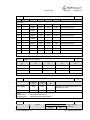
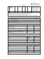
Particulars: test item vs. test requirements
Equipment mobility .......................................: Movable equipment
Operating condition .......................................: Continuous
Mains supply tolerance (%) ...........................: ±10%
Tested for IT power systems ........................: Yes
IT testing, phase-phase voltage (V) ..............: 230V (for Norway)
Class of equipment .......................................: Class I
Mass of equipment (kg).................................: 5.58
Protection against ingress of water ..............: IPX0
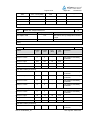
Test case verdicts
Test case does not apply to the test object ..: N/A
Test item does meet the requirement ..........: P(ass)
Test item does not meet the requirement ....: F(ail)
Testing
Date of receipt of test item ...........................: May, 2007
Date(s) of performance of test .....................: May – June, 2007
General remarks
”This report is not valid as a CB Test Report unless appended by an approved CB Testing
Laboratory and appended to a CB Test Certificate issued by an NCB in accordance with IECEE 02”.
The test result presented in this report relate only to the object(s) tested.
This report shall not be reproduced, except in full, without the written approval of the Issuing testing
laboratory.
”(see Enclosure #)" refers to additional information appended to the report.
"(see appended table)" refers to a table appended to the report.
Throughout this report a point is used as the decimal separator.
Comments:
Summary of compliance with National Differences (for explanation of codes see below):
EU Group Differences, EU Special National Conditions, EU A-Deviations, AR, AT, AU, BE, CH, CN, CZ, DE,
DK, FI, FR, GB, GR, HU, IL, IN, IT, KE, KR, MY, NL, NO, PL, SE, SG, SI, SK.
AR=Argentina, AT=Austria, AU=Australia, BE=Belgium, CA=Canada, CH=Switzerland, CN=China,
CZ=Czech Republic, DE=Germany, DK=Denmark, FI=Finland, FR=France, GB=United Kingdom,
GR=Greece, HU=Hungary, IL=Israel, IN=India, IT=Italy, KE=Kenya, KR=Korea, MY=Malaysia, NL=The
Netherlands, NO=Norway, PL=Poland, SE=Sweden, SG=Singapore, SI=Slovenia, SK=Slovakia, US=United
States of America.
For National Differences see end of this test report.
Factories:
1) Lite-On Computer Technology (Dong Guan) Co., Ltd.
N. San Heng Rd., Heng Jiao Ind. Zone, Xi Chen Zone, Shi Jie Town, Dongguan, Guangdong, P.R. China
2) Dongguan shijie yuanli electronics factory
Heng Jiao Ind. Zone, Shi Jie Town, Dong Guan City, Guang Dong Province, P.R. China
Definition of variables:
Variable:
Range of variable:
TRF No.:IECEN60950_1B
Content:
TRF originator: SGS Fimko
Page 5 of 65
*
0-9, A-Z or blank
Report No.:
11010447 001
Marketing purpose only, no technical difference
General product information:
The equipment models P193W**** P191W****, ADAA, X193W****, ADA9 (* can be 0-9, A-Z or blank) are
19” LCD Monitor for the use in information technology equipment.
All models are identical except for model designation.
This equipment consists with following critical components:
- TFT LCD panel module
- Metal enclosure (inside of the plastic enclosure, covering switching power supply with DC/AC inverter
board and function control board) (refer to appended table 1.5.1 for details)
- Building-in type switching power supply with DC/AC inverter board (refer to appended table 1.5.1 for
details)
- Secondary function control board (as main board, SELV circuit, with D-sub and DVI port)
- Plastic enclosure (refer to appended table 1.5.1 for details)
- Key control board (as SELV circuits)
TRF No.:IECEN60950_1B
TRF originator: SGS Fimko
Report No.:
Page 6 of 65
11010447 001
IEC 60950-1 / EN 60950-1
Clause
Requirement – Test
Result – Remark
Verdict
1
GENERAL
P
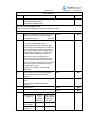
1.5
Components
P
1.5.1
General
See below.
P
Comply with IEC 60950 or relevant component
standard
(see appended table 1.5.1)
P
1.5.2
Evaluation and testing of components
Components, which were
certified to IEC and/or national
standards, are used correctly
within their ratings or had been
evaluated during this approval.
P
1.5.3
Thermal controls
No thermal controls provided.
N/A
1.5.4
Transformers
Transformer used is suitable for
the intended application and
complies with the relevant
requirements of the standard
and particularly with those of
Annex C.
P
1.5.5
Interconnecting cables
Interconnection cable provided
with the equipment is carrying
only SELV on energy level
below 240VA.
N/A
Except the insulation materials
there are no further
requirements for the
interconnection cables.
1.5.6
Capacitors in primary circuits ...............................: Between lines: X2 sub-class
capacitor according to IEC
60384-14:1993 with 21 days
damp heat test.
P
Between Line/Neutral to earth:
Y2 or Y1 sub-class capacitor
according to IEC 6038414:1993.
1.5.7
Double insulation or reinforced insulation bridged
by components
No such components used.
N/A
1.5.7.1
General
See above.
N/A
1.5.7.2
Bridging capacitors
See above.
N/A
1.5.7.3
Bridging resistors
See above.
N/A
1.5.7.4
Accessible parts
1.5.8
Components in equipment for IT power systems
1.6
Power interface
TRF No.:IECEN60950_1B
N/A
Y1 or Y2 subclass capacitors
according to IEC 60384-14:1993
provided between phase and
earth are rated 250Vac min.
P
P
TRF originator: SGS Fimko
Report No.:
Page 7 of 65
11010447 001
IEC 60950-1 / EN 60950-1
Clause
Requirement – Test
Result – Remark
Verdict
1.6.1
AC power distribution systems
TN power system considered.
IT power system for Norway.
P
1.6.2
Input current
(see appended table 1.6.2 for
test result)
P
1.6.3
Voltage limit of hand-held equipment
This appliance is not a handheld equipment.
N/A
1.6.4
Neutral conductor
The neutral is not identified in
the equipment. Basic insulation
for rated voltage between
earthed parts and primary
phases.
1.7
Marking and instructions
1.7.1
Power rating
P
P
See below.
P
Rated voltage(s) or voltage range(s) (V) .............: 100-240
P
Symbol for nature of supply, for d.c. only .............: AC mains only.
N/A
Rated frequency or rated frequency range (Hz) ..: 50/60
P
Rated current (mA or A) ......................................: 1.1
P
Manufacturer’s name or trademark or identification Manufacturer:
mark .....................................................................: Acer Computer (Shanghai)
Limited.
P
Trademark: acer
Type/model or type reference...............................: P193W****, P191W****, ADAA,
X193W****, ADA9
(* can be 0-9, A-Z or blank)
Symbol for Class II equipment only .....................: Class I equipment.
P
N/A
Other symbols ......................................................: Other symbols do not give rise
to misunderstanding.
P
Certification marks ...............................................: See copy of the marking plates.
N/A
1.7.2
Safety instructions
User’s manual provided.
1.7.3
Short duty cycles
Equipment is designed for
continuous operation.
1.7.4
Supply voltage adjustment ...................................: Full range circuit design.
N/A
Methods and means of adjustment; reference to No such supply voltage
installation instructions .........................................: adjustment.
N/A
Power outlets on the equipment ..........................: No standard power outlets
provided.
N/A
1.7.5
TRF No.:IECEN60950_1B
P
N/A
TRF originator: SGS Fimko
Report No.:
Page 8 of 65
11010447 001
IEC 60950-1 / EN 60950-1
Clause
Requirement – Test
Result – Remark
1.7.6
Fuse identification (marking, special fusing
Fuse marking label adjacent to
characteristics, cross-reference) ............................: the fuse holder on PCB:
Verdict
P
F801 T3.15AH 250V
CAUTION: FOR CONTINUED
PROTECTION AGAINST A RISK OF
FIRE REPLACE ONLY TYPE WITH
SAME TYPE AND RATINGS OF FUSE.
1.7.7
Wiring terminals
1.7.7.1
Protective earthing and bonding terminals ..........: Appliance inlet is provided. The
symbol of 60417-1-IEC-5019
was located on PCB.
1.7.7.2
Terminal for a.c. mains supply conductors
The equipment is provided with
appliance inlet, which is for
connection of a detachable type
power supply cord.
N/A
1.7.7.3
Terminals for d.c. mains supply conductors
No such conductors.
N/A
1.7.8
Controls and indicators
See below.
1.7.8.1
Identification, location and marking .....................: The marking and indication of
the stand-by switch is located
that indication of function is
clearly.
P
1.7.8.2
Colours ...............................................................: The colours of the Power LED
indicator are as follows:
- Blue for ON condition
- Amber for power saving mode
P
1.7.8.3
Symbols according to IEC 60417 .........................: Marking according 60417-1IEC- 5009 (line half inside
circle) provided above the
stand-by switch.
P
1.7.8.4
Markings using figures ........................................: No indicators for different
positions of control.
N/A
1.7.9
Isolation of multiple power sources .....................: Single power source only.
N/A
1.7.10
IT power distribution systems
For Norway compliance has to
be evaluated during the
national approved.
N/A
1.7.11
Thermostats and other regulating devices
Neither thermostats nor other
regulating devices provided.
N/A
1.7.12
Language(s) .........................................................: User’s manual provided in
English and German. Marking
label provided in English.
Versions in other languages will
be provided during national
approval.
TRF No.:IECEN60950_1B
P
See below.
P
P
TRF originator: SGS Fimko
Report No.:
Page 9 of 65
11010447 001
IEC 60950-1 / EN 60950-1
Clause
Requirement – Test
Result – Remark
1.7.13
Durability
The marking plate was
subjected to the permanence
of marking test. The marking
plate was rubbed with cloth
soaked with water for 15s and
then again for 15s with the
cloth soaked with petroleum
spirit.
After this test there was no
damage to the marking. The
marking on the label did not
fade. There was no curling of
the marking.
P
1.7.14
Removable parts
No removable parts provided.
N/A
1.7.15
Replaceable batteries
No batteries provided.
N/A
Language(s)..........................................................:
Verdict
1.7.16
Operator access with a tool ..................................: There are no any operator
accessible areas with a tool
defined.
N/A
1.7.17
Equipment for restricted access locations ............: No restricted access locations.
N/A
2
PROTECTION FROM HAZARDS
P
2.1
Protection from electric shock and energy hazards
P
2.1.1
Protection in operator access areas
No hazard in operator
accessible areas.
P
2.1.1.1
Access to energized parts
See sub clause 2.1.1
P
Test by inspection ................................................: No access with test finger to
any parts with only basic
insulation to hazardous voltage.
The test pin cannot touch
hazardous voltage parts
through any seams/openings of
the metal enclosure.
P
Test with test finger ..............................................: See above.
P
Test with test pin ..................................................: See above.
P
Test with test probe .............................................: No TNV circuit.
N/A
2.1.1.2
Battery compartments .........................................: No battery compartments
provided.
N/A
2.1.1.3
Access to ELV wiring
N/A
No ELV wiring in operator
access area.
Working voltage (Vpeak or Vrms); minimum
distance (mm) through insulation
2.1.1.4
Access to hazardous voltage circuit wiring
TRF No.:IECEN60950_1B
No hazardous voltage circuit in
operator access area.
N/A
TRF originator: SGS Fimko
Report No.:
Page 10 of 65
11010447 001
IEC 60950-1 / EN 60950-1
Clause
Requirement – Test
Result – Remark
2.1.1.5
Energy hazards ....................................................: No energy hazard in operator
access area.
2.1.1.6
Manual controls
No conductive shafts of
operating knobs and handles.
2.1.1.7
Discharge of capacitors in equipment
No risk of electric shock.
Time-constant (s); measured voltage (V) .............: (See appended table)
Verdict
P
N/A
P
2.1.2
Protection in service access areas
No maintenance works in
operation mode necessary.
N/A
2.1.3
Protection in restricted access locations
The unit is not limited to be used
in restricted access locations.
N/A
2.2
SELV circuits
2.2.1
General requirements
2.2.2
Voltages under normal conditions (V) ..................: Between any conductor of the
SELV circuits, 42.4Vpeak or
60Vd.c. are not exceeded.
Result see appended table
2.2.2.
P
2.2.3
Voltages under fault conditions (V).......................: Single fault did not cause
excessive voltage in SELV
circuits. The limits of 71Vpeak
and 120Vd.c. were not exceed.
Furthermore, the SELV limits
(see sub clause 2.2.2) were not
exceeded for longer than 0.2
seconds. Results see
appended tables 2.2.2 and
2.2.3.
P
2.2.3.1
Separation by double insulation or reinforced
insulation (method 1)
Method 1 used.
P
2.2.3.2
Separation by earthed screen (method 2)
Used for C802 and C832 trace.
P
2.2.3.3
Protection by earthing of the SELV circuit
(method 3)
2.2.4
Connection of SELV circuits to other circuits........: See sub clause 2.2.2, 2.2.3.
and 2.4.3.
2.3
TNV circuits
N/A
2.3.1
Limits
N/A
2.3.2
2.3.3
P
P
See below.
N/A
P
Type of TNV circuits .............................................:
Separation from other circuits and from accessible
parts
N/A
Insulation employed..............................................:
Separation from hazardous voltages
TRF No.:IECEN60950_1B
N/A
TRF originator: SGS Fimko
Report No.:
Page 11 of 65
11010447 001
IEC 60950-1 / EN 60950-1
Clause
Requirement – Test
Result – Remark
Insulation employed..............................................:
2.3.4
Verdict
Connection of TNV circuits to other circuits
N/A
Insulation employed..............................................:
2.3.5
Test for operating voltages generated externally
2.4
Limited current circuits
2.4.1
General requirements
Considered for output of
DC/AC inverter.
P
2.4.2
Limit values
See appended table 2.4.2.
P
Frequency (Hz) .....................................................: See appended table 2.4.2.
Measured current (mA).........................................: The peak drop voltage was
measured with an oscilloscope
at a 2kΩ non-inductive resistor.
Results see appended table
2.4.2.
Measured voltage (V) ...........................................: 970V
Measured capacitance (µF) ..................................: 10pF
2.4.3
Connection of limited current circuits to other
circuits
P
2.5
Limited power sources
N/A
P
Complies.
P
+5.25Vdc and +22Vdc output of switching power supply with DC/AC inverter board
were complied with L.P.S test requirement.
Inherently limited output
N/A
Impedance limited output
N/A
Overcurrent protective device limited output
N/A
Regulating network limited output under normal
operating and single fault condition
Output of +5.25Vdc and
+22Vdc of switching power
supply with DC/AC inverter
board (connect to main board)
were complied with L.P.S test.
See appended table for test
result.
Regulating network limited output under normal
operating conditions and overcurrent protective
device limited output under single fault condition
2.6
P
N/A
Output voltage (V), output current (A), apparent
Results see appended table
power (VA)............................................................: 2.5.
Current rating of overcurrent protective device (A)
Provisions for earthing and bonding
P
TRF No.:IECEN60950_1B
TRF originator: SGS Fimko
Report No.:
Page 12 of 65
11010447 001
IEC 60950-1 / EN 60950-1
Clause
Requirement – Test
Result – Remark
Verdict
2.6.1
Protective earthing
Appliance inlet directly
connects to PCB (by solder pin)
and also with screw reliable
connection to metal enclosure.
P
2.6.2
Functional earthing
Secondary functional earthing
is separated to primary by
double or reinforce insulation or
by basic insulation and
protective earthing.
P
No green/yellow wire used at
secondary.
2.6.3
Protective earthing and protective bonding
conductors
See below.
P
2.6.3.1
General
No power supply cord provided.
See sub clause 2.6.3.4.
P
2.6.3.2
Size of protective earthing conductors
No power cord provided.
2
Rated current (A), cross-sectional area (mm ),
AWG .....................................................................:
2.6.3.3
Size of protective bonding conductors
N/A
Evaluation by test. Rated
current below 16A.
N/A
Rated current (A), cross-sectional area (mm2),
AWG .....................................................................:
2.6.3.4
Resistance (Ω) of earthing conductors and their
(Refer to appended table
terminations, test current (A) ................................: 2.6.3.4).
P
2.6.3.5
Colour of insulation ...............................................: No green/yellow wire used.
2.6.4
Terminals
See below.
P
2.6.4.1
General
See sub clause 2.6.1.
P
2.6.4.2
Protective earthing and bonding terminals
The earth terminal of appliance
inlet is considered as the
protective earthing terminal and
was evaluated by sub clause
2.6.3.4.
P
Rated current (A), type and nominal thread
Evaluation by test. Rated
diameter (mm) ......................................................: current below 16A.
N/A
2.6.4.3
Separation of the protective earthing conductor
from protective bonding conductors
Only protective earthing
conductor used in this
equipment.
2.6.5
Integrity of protective earthing
See below.
P
2.6.5.1
Interconnection of equipment
This unit has it's own earthing
connection. Any other units
connected via the output shall
be provided SELV only.
P
TRF No.:IECEN60950_1B
N/A
TRF originator: SGS Fimko
Report No.:
Page 13 of 65
11010447 001
IEC 60950-1 / EN 60950-1
Clause
Requirement – Test
Result – Remark
Verdict
2.6.5.2
Components in protective earthing conductors
and protective bonding conductors
No switch or overcurrent
protective device in protective
earthing conductor.
P
2.6.5.3
Disconnection of protective earth
Appliance inlet provided as
disconnection device disconnect
at one point in the unit.
P
2.6.5.4
Parts that can be removed by an operator
Plug or inlet, the earth
connection is made before and
broken after the hazardous
voltage. No other operator
removable parts.
P
2.6.5.5
Parts removed during servicing
It is not necessary to disconnect
the earth connection except for
the removing of the earthed part
itself.
P
2.6.5.6
Corrosion resistance
All safety earthing connections
in compliance with Annex J.
P
2.6.5.7
Screws for protective bonding
Only ISO thread screw used in
metal enclosure for protective
bonding. Metal thickness at
least twice the pitch of the
screw.
P
No self-tapping or spaced
thread screws used.
2.6.5.8
Reliance on telecommunication network or cable
distribution system
2.7
Overcurrent and earth fault protection in primary circuits
P
2.7.1
Basic requirements
Equipment relies on fuse or
circuit breaker of the wall outlet
installation protection of the
building installation in regard to
L to N short circuit and earth
fault. Over current protection is
provided by one built-in fuse.
P
Instructions when protection relies on building
installation
Pluggable equipment type A.
2.7.2
Faults not covered in 5.3
The protection devices are well
dimensioned and mounted.
P
2.7.3
Short-circuit backup protection
Pluggable equipment type A, the
building installation is
considered as providing short
circuit backup protection.
P
2.7.4
Number and location of protective devices ..........: One built-in fuse provided on the
mains conductor.
P
2.7.5
Protection by several devices
TRF No.:IECEN60950_1B
No TNV circuits provided.
One fuse provided.
N/A
N/A
N/A
TRF originator: SGS Fimko
Report No.:
Page 14 of 65
11010447 001
IEC 60950-1 / EN 60950-1
Clause
Requirement – Test
Result – Remark
Verdict
2.7.6
Warning to service personnel ...............................: No service work necessary.
N/A
2.8
Safety interlocks
N/A
2.8.1
General principles
N/A
2.8.2
Protection requirements
N/A
2.8.3
Inadvertent reactivation
N/A
2.8.4
Fail-safe operation
N/A
2.8.5
Moving parts
N/A
2.8.6
Overriding
N/A
2.8.7
Switches and relays
N/A
2.8.7.1
Contact gaps (mm) ..............................................:
N/A
2.8.7.2
Overload test
N/A
2.8.7.3
Endurance test
N/A
2.8.7.4
Electric strength test
N/A
2.8.8
Mechanical actuators
N/A
2.9
Electrical insulation
2.9.1
Properties of insulating materials
Natural rubber, asbestos or
hygroscopic materials are not
used.
P
2.9.2
Humidity conditioning
Carried out for 120 hrs.
P
P
Humidity (%) ........................................................: 95% R.H.
Temperature (°C) .................................................: 40°C
2.9.3
Grade of insulation
P
2.10
Clearances, creepage distances and distances through insulation
P
2.10.1
General
See below.
P
2.10.2
Determination of working voltage
The rms and the peak voltages
were measured for the unit.
P
Adequate levels of safety
insulation were provided and
maintained to comply with the
requirements of this standard.
The unit was connected to a
240V TN power system.
Results see appended table
2.10.2.
2.10.3
Clearances
TRF No.:IECEN60950_1B
See below, Annex G was not
considered.
P
TRF originator: SGS Fimko
Report No.:
Page 15 of 65
11010447 001
IEC 60950-1 / EN 60950-1
Clause
Requirement – Test
Result – Remark
Verdict
2.10.3.1
General
Annex F and minimum
clearances considered.
P
2.10.3.2
Clearances in primary circuits
(see appended table 2.10.3
and 2.10.4)
P
2.10.3.3
Clearances in secondary circuits
See sub clause 5.3.4.
N/A
2.10.3.4
Measurement of transient voltage levels
Normal transient voltage
considered (overvoltage
category II for primary circuits).
N/A
2.10.4
Creepage distances
(see appended table 2.10.3
and 2.10.4)
P
CTI tests ...............................................................: CTI rating for all materials of
min. 100.
2.10.5
Solid insulation
See below.
P
2.10.5.1
Minimum distance through insulation
(see appended table 2.10.5)
P
2.10.5.2
Thin sheet material
The thin sheet materials of
polyester tape used in
transformer T802.
P
2.10.5.3
Number of layers (pcs) .........................................: 3 layers.
Electric strength test
(see appended table 5.2)
Printed boards
N/A
Distance through insulation
N/A
Electric strength test for thin sheet insulating
material
2.10.5.4
Number of layers (pcs) .........................................:
N/A
Wound components
N/A
Number of layers (pcs) .........................................:
N/A
Two wires in contact inside wound component;
angle between 45° and 90° ..................................:
N/A
2.10.6
Coated printed boards
2.10.6.1
General
N/A
2.10.6.2
Sample preparation and preliminary inspection
N/A
2.10.6.3
Thermal cycling
N/A
2.10.6.4
Thermal ageing (°C) .............................................:
N/A
2.10.6.5
Electric strength test
2.10.6.6
Abrasion resistance test
No coated printed boards.
N/A
Electric strength test
2.10.7
N/A
Enclosed and sealed parts ...................................: No hermetically sealed
components.
N/A
Temperature T1=T2 + Tma – Tamb +10K (°C)....:
N/A
TRF No.:IECEN60950_1B
TRF originator: SGS Fimko
Report No.:
Page 16 of 65
11010447 001
IEC 60950-1 / EN 60950-1
Clause
Requirement – Test
2.10.8
Spacings filled by insulating compound................: Certified sources of optical
isolators used. No other
components applied for. (see
appended table 2.10.5).
P
Electric strength test
See above.
2.10.9
Component external terminations
See appended table 1.5.1,
2.10.3 and 2.10.4.
P
2.10.10
Insulation with varying dimensions
No reduction of distance
applied.
3
WIRING, CONNECTIONS AND SUPPLY
P
3.1
General
P
3.1.1
Current rating and overcurrent protection
All internal wires are UL
recognized wiring, which is
PVC insulated, rated VW-1,
min. 80°C. Internal wiring
gauge is suitable for current
intended to be carried.
P
3.1.2
Protection against mechanical damage
Wires do not touch sharp
edges and heatsinks, which
could damage the insulation.
P
3.1.3
Securing of internal wiring
Internal wires are secured by
solder, cable tie or other
mechenical connect so that a
loosening of the terminal
connection is unlikely.
P
3.1.4
Insulation of conductors
The insulation of the individual
conductors is suitable for the
application and the working
voltage. For the insulation
material see 3.1.1.
P
3.1.5
Beads and ceramic insulators
Not used.
3.1.6
Screws for electrical contact pressure
Electrical and earthing
connections screwed two or
more complete threads into
metal. No screws of insulating
material for electrical and
earthing connections.
P
3.1.7
Insulating materials in electrical connections
To ensure proper earth
connection through the PCB,
screws and spring-washers are
provided to compensate
possible shrinkage of the PCB
material.
P
3.1.8
Self-tapping and spaced thread screws
No self-tapping or spaced
thread screws used.
TRF No.:IECEN60950_1B
Result – Remark
Verdict
N/A
N/A
N/A
TRF originator: SGS Fimko
Report No.:
Page 17 of 65
11010447 001
IEC 60950-1 / EN 60950-1
Clause
Requirement – Test
Result – Remark
3.1.9
Termination of conductors
All conductors are reliable
secured.
P
10 N pull test
Complied.
P
3.1.10
Sleeving on wiring
No sleeving used as
supplementary insulation
function.
3.2
Connection to an a.c. mains supply or a d.c. mains supply
P
3.2.1
Means of connection ............................................: See below.
P
3.2.1.1
Connection to an a.c. mains supply
P
3.2.1.2
Connection to a d.c. mains supply
3.2.2
Multiple supply connections
Only one AC mains supply
connection.
N/A
3.2.3
Permanently connected equipment
Not permanently connected
equipment.
N/A
Appliance inlet used.
Verdict
N/A
N/A
Number of conductors, diameter (mm) of cable
and conduits ........................................................:
3.2.4
Appliance inlets
The appliance inlet complies
with IEC 60320-1. The power
cord can be inserted without
difficulties and does not support
the unit.
3.2.5
Power supply cords
Not provided.
N/A
3.2.5.1
AC power supply cords
See above.
N/A
Type......................................................................:
P
2
Rated current (A), cross-sectional area (mm ),
AWG .....................................................................:
3.2.5.2
DC power supply cords
Not connect to DC mains.
N/A
3.2.6
Cord anchorages and strain relief
No non-detachable power
supply cords provided.
N/A
Mass of equipment (kg), pull (N) ........................:
Longitudinal displacement (mm) ..........................:
3.2.7
Protection against mechanical damage
No parts under this unit likely to
damage the power supply
cords. Enclosure without sharp
edges.
3.2.8
Cord guards
No cord guard provided.
3.2.9
P
N/A
D (mm); test mass (g) ..........................................:
Radius of curvature of cord (mm).........................:
Supply wiring space
TRF No.:IECEN60950_1B
Not permanently connected
and without non-detachable
power supply cord.
N/A
TRF originator: SGS Fimko
Report No.:
Page 18 of 65
11010447 001
IEC 60950-1 / EN 60950-1
Clause
Requirement – Test
Result – Remark
3.3
Wiring terminals for connection of external conductors
Verdict
N/A
Neither permanently connected nor non-detachable equipment.
3.3.1
Wiring terminals
N/A
3.3.2
Connection of non-detachable power supply
cords
N/A
3.3.3
Screw terminals
N/A
3.3.4
Conductor sizes to be connected
N/A
Rated current (A), cord/cable type, cross-sectional
area (mm2) ...........................................................:
3.3.5
Wiring terminal sizes
N/A
Rated current (A), type and nominal thread
diameter (mm) .....................................................:
3.3.6
Wiring terminals design
N/A
3.3.7
Grouping of wiring terminals
N/A
3.3.8
Stranded wire
N/A
3.4
Disconnection from the mains supply
3.4.1
General requirement
See below.
P
3.4.2
Disconnect devices
Appliance inlet used as
disconnect divice.
P
3.4.3
Permanently connected equipment
Not permanently connected
equipment.
3.4.4
Parts which remain energized
When the power cord is
removed from the inlet no
remaining parts with hazardous
voltage in the equipment.
3.4.5
Switches in flexible cords
No power supply cords
provided.
3.4.6
Single-phase equipment and d.c. equipment
Both poles are disconnected
simultaneously.
3.4.7
Three-phase equipment
Single-phase equipment.
N/A
3.4.8
Switches as disconnect devices
No switch provided.
N/A
3.4.9
Plugs as disconnect devices
See sub clause 3.4.2.
N/A
3.4.10
Interconnected equipment
Interconnection of the power
supply to the other PCBs in the
equipment by secondary output
cable only.
N/A
3.4.11
Multiple power sources
Only one supply connection
provided.
N/A
TRF No.:IECEN60950_1B
P
N/A
P
N/A
P
TRF originator: SGS Fimko
Report No.:
Page 19 of 65
11010447 001
IEC 60950-1 / EN 60950-1
Clause
Requirement – Test
3.5
Interconnection of equipment
3.5.1
General requirements
3.5.2
Types of interconnection circuits ..........................: Interconnection circuits of
SELV through the connector.
3.5.3
ELV circuits as interconnection circuits
4
PHYSICAL REQUIREMENTS
P
4.1
Stability
P
Angle of 10°
Result – Remark
Verdict
P
P
See below.
No ELV interconnection.
The equipment does not
overbalance when tilted to 10
degrees.
Test: force (N).......................................................: Equipment is not a floor
standing unit.
P
N/A
P
N/A
4.2
Mechanical strength
4.2.1
General
See below. After the tests, the
equipment complies with the
requirements of sub-clauses
2.1.1, 2.6.1 and 2.10.
P
4.2.2
Steady force test, 10 N
10N applied to components
other than parts serving as an
enclosure.
P
4.2.3
Steady force test, 30 N
4.2.4
Steady force test, 250 N
250N applied to internal metal
enclosure at top, side, bottom
and rear. No energy or other
hazards.
P
4.2.5
Impact test
No hazard as result from steel
ball impact test for metal
enclosure.
P
Fall test
See above.
P
Swing test
See above.
P
4.2.6
Drop test
4.2.7
Stress relief test
P
N/A
N/A
The internal metal enclosure
considered as fire, electrical and
mechenical enclosure and no
energy hazard in operator
access area.
N/A
Complied with sub-clause 2.1.1,
2.6.1 and 2.10.
4.2.8
Cathode ray tubes
Picture tube separately certified ...........................:
TRF No.:IECEN60950_1B
No CRT provided.
N/A
N/A
TRF originator: SGS Fimko
Report No.:
Page 20 of 65
11010447 001
IEC 60950-1 / EN 60950-1
Clause
Requirement – Test
Result – Remark
Verdict
4.2.9
High pressure lamps
No high pressure lamps
provided.
4.2.10
Wall or ceiling mounted equipment; force (N) .....:
4.3
Design and construction
4.3.1
Edges and corners
4.3.2
Handles and manual controls; force (N) ...............: None, which could cause
hazards.
N/A
4.3.3
Adjustable controls
No safety relevant adjustable
controls provided.
N/A
4.3.4
Securing of parts
Electrical and mechanical
connections can be expected
to withstand usual mechanical
stress. No loosening of
clearance or creepage
impairing distances likely to
occur.
P
4.3.5
Connection of plugs and sockets
No mismatch of connectors,
plugs or socket possible.
P
4.3.6
Direct plug-in equipment
Not direct plug-in type.
N/A
N/A
P
The edges and corners are
rounded and smoothed.
P
N/A
Dimensions (mm) of mains plug for direct plug-in :
N/A
Torque and pull test of mains plug for direct
plug-in; torque (Nm); pull (N) ................................:
N/A
4.3.7
Heating elements in earthed equipment
No heating elements.
N/A
4.3.8
Batteries
No batteries provided.
N/A
4.3.9
Oil and grease
No oil or grease inside the
equipment.
N/A
4.3.10
Dust, powders, liquids and gases
Equipment intended use not
considered to be exposed to
these.
N/A
4.3.11
Containers for liquids or gases
No container for liquid or gas.
N/A
4.3.12
Flammable liquids.................................................: No flammable liquid.
N/A
Quantity of liquid (l) ...............................................:
N/A
Flash point (°C).....................................................:
N/A
4.3.13
Radiation; type of radiation ..................................: See below.
4.3.13.1
General
4.3.13.2
Ionizing radiation
TRF No.:IECEN60950_1B
P
No radiation is generated inside
the equipment. The energy of
the indicator LED is far below
the limit for Class 1 LED
products.
N/A
N/A
TRF originator: SGS Fimko
Report No.:
Page 21 of 65
11010447 001
IEC 60950-1 / EN 60950-1
Clause
4.3.13.3
Requirement – Test
Result – Remark
Verdict
Measured radiation (pA/kg) .................................:
Measured high-voltage (kV) ................................:
Measured focus voltage (kV) ...............................:
CRT markings .....................................................:
Effect of ultraviolet (UV) radiation on materials
N/A
Part, property, retention after test, flammability
classification ........................................................:
N/A
4.3.13.4
Human exposure to ultraviolet (UV) radiation ......:
N/A
4.3.13.5
Laser (including LEDs)
No laser presents. LED power is
far below LED Class 1 limit.
Laser class ...........................................................: See above.
P
4.3.13.6
Other types ..........................................................: Not used.
N/A
4.4
Protection against hazardous moving parts
N/A
4.4.1
General
N/A
4.4.2
Protection in operator access areas
N/A
4.4.3
Protection in restricted access locations
N/A
4.4.4
Protection in service access areas
N/A
4.5
Thermal requirements
4.5.1
Maximum temperatures
P
(see appended table 4.5.1)
P
Normal load condition per Annex L.......................: Considered.
P
4.5.2
Resistance to abnormal heat
P
4.6
Openings in enclosures
4.6.1
Top and side openings
4.6.2
Phenolic materials used where
parts at hazardous voltage are
directly mounted on. Phenolic
is accepted without further
testing. For other material test
result, refer to appended table
4.5.2.
P
P
See below.
Dimensions (mm) ................................................: (see appended table)
Bottoms of fire enclosures
P
See below.
Construction of the bottom ...................................: (see appended table)
4.6.3
Doors or covers in fire enclosures
No doors or covers provided.
N/A
4.6.4
Openings in transportable equipment
Equipment not transportable
type.
N/A
TRF No.:IECEN60950_1B
TRF originator: SGS Fimko
Report No.:
Page 22 of 65
11010447 001
IEC 60950-1 / EN 60950-1
Clause
Requirement – Test
Result – Remark
4.6.5
Adhesives for constructional purposes
No adhesives used.
Verdict
N/A
Conditioning temperature (°C)/time (weeks) ........:
4.7
Resistance to fire
P
4.7.1
Reducing the risk of ignition and spread of flame
See below.
P
Method 1, selection and application of
components wiring and materials
Materials with suitable
flammability classes are used.
P
Method 2, application of all of simulated fault
condition tests
Not used.
N/A
4.7.2
Conditions for a fire enclosure
See below.
P
4.7.2.1
Parts requiring a fire enclosure
Fire enclosure is required if at
least one of the following is
provided:
P
●
components in primary
●
components in secondary
(not supplied by LPS)
●
insulated wiring
Fire enclosure (internal metal
enclosure was considered as
fire enclosure) is required.
4.7.2.2
Parts not requiring a fire enclosure
4.7.3
Materials
4.7.3.1
General
PCB rated accordingly. For
details see table 1.5.1.
P
4.7.3.2
Materials for fire enclosures
Internal metal enclosure was
considered as fire enclosure.
P
4.7.3.3
Materials for components and other parts outside
fire enclosures
Base stand and plastic
enclosure outside of fire
enclosure used material rated
HB or better.
P
4.7.3.4
Materials for components and other parts inside
fire enclosures
Internal components except
small parts are V-2 or better.
P
4.7.3.5
Materials for air filter assemblies
No air filters provided.
N/A
4.7.3.6
Materials used in high-voltage components
No high voltage components
provided.
N/A
TRF No.:IECEN60950_1B
The fire enclosure is not
required for the circuits
(supplied by LPS and mounted
on PCB material of flammability
rating V-1) which outside the
power supply with DC/AC
inverter board. The outer plastic
enclosure used HB plastic
material.
P
P
TRF originator: SGS Fimko
Report No.:
Page 23 of 65
11010447 001
IEC 60950-1 / EN 60950-1
Clause
Requirement – Test
Result – Remark
Verdict
5
ELECTRICAL REQUIREMENTS AND SIMULATED ABNORMAL CONDITIONS
P
5.1
Touch current and protective conductor current
P
5.1.1
General
See sub-clauses 5.1.2 to 5.1.6.
P
5.1.2
Equipment under test (EUT)
EUT has only one mains
connection.
P
5.1.3
Test circuit
Equipment of figure 5A used.
P
5.1.4
Application of measuring instrument
See appended table 5.1.6.
P
5.1.5
Test procedure
The touch current was
measured from mains to
earthed metal enclosure,
earthed output connector and
plastic enclosures with metal
foil.
P
5.1.6
Test measurements
See appended table 5.1.6.
P
Test voltage (V) ...................................................: See above.
Measured touch current (mA) ..............................: See above.
Max. allowed touch current (mA) .........................: See above.
Measured protective conductor current (mA) ......:
Max. allowed protective conductor current (mA) .:
5.1.7
Equipment with touch current exceeding 3.5 mA : Touch current does not exceed
3.5mA.
N/A
5.1.8
Touch currents to and from telecommunication
No TNV circuit connection.
networks and cable distribution systems and from
telecommunication networks
N/A
5.1.8.1
Limitation of the touch current to a
telecommunication network and a cable
distribution system
N/A
No TNV circuit connection.
Test voltage (V) ...................................................:
Measured touch current (mA) ..............................:
Max. allowed touch current (mA) .........................:
5.1.8.2
Summation of touch currents from
No TNV circuit connection.
telecommunication networks ................................:
5.2
Electric strength
5.2.1
General
(see appended table 5.2)
P
5.2.2
Test procedure
(see appended table 5.2)
P
5.3
Abnormal operating and fault conditions
TRF No.:IECEN60950_1B
N/A
P
P
TRF originator: SGS Fimko
Report No.:
Page 24 of 65
11010447 001
IEC 60950-1 / EN 60950-1
Clause
Requirement – Test
Result – Remark
5.3.1
Protection against overload and abnormal
operation
See below.
5.3.2
Motors
No motors used.
5.3.3
Transformers
With the overload and shorted
output of the transformer, no
high temperature of the
transformer was recorded.
Verdict
P
N/A
P
Results of the overload and
short-circuit tests see appended
table 5.3 and Annex C.
5.3.4
Functional insulation .............................................: Method c). Test results see
appended table 5.3.
5.3.5
Electromechanical components
No electromechanical
component provided.
5.3.6
Simulation of faults
Ventilation blocked: Results
see appended table.
P
N/A
P
Short and open circuit test for
power supply board. Result see
appended table.
5.3.7
Unattended equipment
None of the listed components
was provided.
N/A
5.3.8
Compliance criteria for abnormal operating and
fault conditions
No fire occurs. No molten metal
was emitted. Electric strength
tests primary to secondary and
primary to earth passed.
P
6
CONNECTION TO TELECOMMUNICATION NETWORKS
N/A
6.1
Protection of telecommunication network service persons, and users of other
equipment connected to the network, from hazards in the equipment
N/A
6.1.1
Protection from hazardous voltages
N/A
6.1.2
Separation of the telecommunication network from earth
N/A
6.1.2.1
Requirements
N/A
Test voltage (V) ...................................................:
Current in the test circuit (mA) ............................:
6.1.2.2
Exclusions.............................................................:
N/A
6.2
Protection of equipment users from overvoltages on telecommunication networks
N/A
6.2.1
Separation requirements
N/A
6.2.2
Electric strength test procedure
N/A
6.2.2.1
Impulse test
N/A
6.2.2.2
Steady-state test
N/A
TRF No.:IECEN60950_1B
TRF originator: SGS Fimko
Report No.:
Page 25 of 65
11010447 001
IEC 60950-1 / EN 60950-1
Clause
Requirement – Test
Result – Remark
Verdict
6.2.2.3
Compliance criteria
N/A
6.3
Protection of the telecommunication wiring system from overheating
N/A
Max. output current (A) .........................................:
Current limiting method ........................................:
7
CONNECTION TO CABLE DISTRIBUTION SYSTEMS
N/A
7.1
Protection of cable distribution system service
persons, and users of other equipment
connected to the system, from hazardous
voltages in the equipment
N/A
7.2
Protection of equipment users from overvoltages
on the cable distribution system
N/A
7.3
Insulation between primary circuits and cable
distribution systems
N/A
7.3.1
General
N/A
7.3.2
Voltage surge test
N/A
7.3.3
Impulse test
N/A
A
ANNEX A, TESTS FOR RESISTANCE TO HEAT AND FIRE
N/A
A.1
Flammability test for fire enclosures of movable equipment having a total mass
exceeding 18 kg, and of stationary equipment (see 4.7.3.2)
N/A
A.1.1
Samples................................................................:
Wall thickness (mm) .............................................:
A.1.2
Conditioning of samples; temperature (°C) ..........:
N/A
A.1.3
Mounting of samples ............................................:
N/A
A.1.4
Test flame (see IEC 60695-11-3)
N/A
Flame A, B, C or D ...............................................:
A.1.5
Test procedure
N/A
A.1.6
Compliance criteria
N/A
Sample 1 burning time (s) ....................................:
Sample 2 burning time (s) ....................................:
Sample 3 burning time (s) ....................................:
A.2
Flammability test for fire enclosures of movable equipment having a total mass not
exceeding 18 kg, and for material and components located inside fire enclosures
(see 4.7.3.2 and 4.7.3.4)
A.2.1
Samples, material.................................................:
Wall thickness (mm) .............................................:
A.2.2
Conditioning of samples
TRF No.:IECEN60950_1B
N/A
N/A
TRF originator: SGS Fimko
Report No.:
Page 26 of 65
11010447 001
IEC 60950-1 / EN 60950-1
Clause
Requirement – Test
Result – Remark
A.2.3
Mounting of samples ...........................................:
N/A
A.2.4
Test flame (see IEC 60695-11-4)
N/A
Flame A, B or C ...................................................:
Verdict
A.2.5
Test procedure
N/A
A.2.6
Compliance criteria
N/A
A.2.7
Sample 1 burning time (s) ....................................:
Sample 2 burning time (s) ....................................:
Sample 3 burning time (s) ....................................:
Alternative test acc. to IEC 60695-2-2, cl. 4 and 8
N/A
Sample 1 burning time (s) ....................................:
Sample 2 burning time (s) ....................................:
Sample 3 burning time (s) ....................................:
A.3
Hot flaming oil test (see 4.6.2)
N/A
A.3.1
Mounting of samples
N/A
A.3.2
Test procedure
N/A
A.3.3
Compliance criterion
N/A
B
ANNEX B, MOTOR TESTS UNDER ABNORMAL CONDITIONS (see 4.7.2.2 and
5.3.2)
N/A
B.1
General requirements
N/A
Position ................................................................:
Manufacturer ........................................................:
Type .....................................................................:
Rated values .......................................................:
B.2
Test conditions
N/A
B.3
Maximum temperatures
N/A
B.4
Running overload test
N/A
B.5
Locked-rotor overload test
N/A
Test duration (days) .............................................:
Electric strength test: test voltage (V) ..................:
B.6
Running overload test for d.c. motors in
secondary circuits
N/A
B.7
Locked-rotor overload test for d.c. motors in secondary circuits
N/A
B.7.1
Test procedure
N/A
B.7.2
Alternative test procedure; test time (h)................:
N/A
B.7.3
Electric strength test
N/A
TRF No.:IECEN60950_1B
TRF originator: SGS Fimko
Report No.:
Page 27 of 65
11010447 001
IEC 60950-1 / EN 60950-1
Clause
Requirement – Test
Result – Remark
Verdict
B.8
Test for motors with capacitors
N/A
B.9
Test for three-phase motors
N/A
B.10
Test for series motors
N/A
Operating voltage (V) ...........................................:
ANNEX C, TRANSFORMERS (see 1.5.4 and 5.3.3)
P
Position ................................................................: (see appended table C.2)
Manufacturer ........................................................: (see appended table C.2)
Type .....................................................................: (see appended table C.2)
Rated values .......................................................: Class B
Method of protection .............................................: By the circuit design.
C.1
Overload test
(see appended table 5.3)
P
C.2
Insulation
(see appended table C.2)
P
Protection from displacement of windings ............: (see appended table C.2)
P
D
ANNEX D, MEASURING INSTRUMENTS FOR TOUCH-CURRENT TESTS
(see 5.1.4)
P
D.1
Measuring instrument
P
D.2
Alternative measuring instrument
N/A
E
ANNEX E, TEMPERATURE RISE OF A WINDING (see 1.4.13)
N/A
F
ANNEX F, MEASUREMENT OF CLEARANCES AND CREEPAGE DISTANCES
(see 2.10)
G
ANNEX G, ALTERNATIVE METHOD FOR DETERMINING MINIMUM
CLEARANCES
N/A
G.1
Summary of the procedure for determining
minimum clearances
N/A
G.2
Determination of mains transient voltage (V) .......:
N/A
G.2.1
AC mains supply
N/A
G.2.2
DC mains supply
N/A
G.3
Determination of telecommunication network
transient voltage (V)..............................................:
N/A
G.4
Determination of required withstand voltage (V)...:
N/A
G.5
Measurement of transient levels (V).....................:
N/A
G.6
Determination of minimum clearances .................:
N/A
C
TRF No.:IECEN60950_1B
See sub clause 5.1.3 and 5.1.4
P
TRF originator: SGS Fimko
Report No.:
Page 28 of 65
11010447 001
IEC 60950-1 / EN 60950-1
Clause
Requirement – Test
Result – Remark
Verdict
H
ANNEX H, IONIZING RADIATION (see 4.3.13)
J
ANNEX J, TABLE OF ELECTROCHEMICAL POTENTIALS (see 2.6.5.6)
P
Metal used ...........................................................: Complied.
N/A
K
ANNEX K, THERMAL CONTROLS (see 1.5.3 and 5.3.7)
N/A
K.1
Making and breaking capacity
N/A
K.2
Thermostat reliability; operating voltage (V) .........:
N/A
K.3
Thermostat endurance test; operating voltage
(V) .......................................................................:
N/A
K.4
Temperature limiter endurance; operating voltage
(V) ........................................................................:
N/A
K.5
Thermal cut-out reliability
N/A
K.6
Stability of operation
N/A
L
ANNEX L, NORMAL LOAD CONDITIONS FOR SOME TYPES OF ELECTRICAL
BUSINESS EQUIPMENT (see 1.2.2.1 and 4.5.1)
L.1
Typewriters
N/A
L.2
Adding machines and cash registers
N/A
L.3
Erasers
N/A
L.4
Pencil sharpeners
N/A
L.5
Duplicators and copy machines
N/A
L.6
Motor-operated files
N/A
L.7
Other business equipment
M
ANNEX M, CRITERIA FOR TELEPHONE RINGING SIGNALS (see 2.3.1)
N/A
M.1
Introduction
N/A
M.2
Method A
N/A
M.3
Method B
N/A
M.3.1
Ringing signal
N/A
M.3.1.1
Frequency (Hz) ....................................................:
M.3.1.2
Voltage (V) ...........................................................:
M.3.1.3
Cadence; time (s), voltage (V) .............................:
M.3.1.4
Single fault current (mA) .......................................:
M.3.2
Tripping device and monitoring voltage ................:
N/A
M.3.2.1
Conditions for use of a tripping device or a
monitoring voltage
N/A
TRF No.:IECEN60950_1B
See sub clause 1.6.2.
P
P
TRF originator: SGS Fimko
Report No.:
Page 29 of 65
11010447 001
IEC 60950-1 / EN 60950-1
Clause
Requirement – Test
Result – Remark
Verdict
M.3.2.2
Tripping device
N/A
M.3.2.3
Monitoring voltage (V)...........................................:
N/A
N
ANNEX N, IMPULSE TEST GENERATORS (see 2.10.3.4, 6.2.2.1, 7.3.2 and
clause G.5)
N/A
N.1
ITU-T impulse test generators
N/A
N.2
IEC 60065 impulse test generator
N/A
P
ANNEX P, NORMATIVE REFERENCES
P
Q
ANNEX Q, BIBLIOGRAPHY
P
R
ANNEX R, EXAMPLES OF REQUIREMENTS FOR QUALITY CONTROL
PROGRAMMES
N/A
R.1
Minimum separation distances for unpopulated
coated printed boards (see 2.10.6)
N/A
R.2
Reduced clearances (see 2.10.3)
N/A
S
ANNEX S, PROCEDURE FOR IMPULSE TESTING (see 6.2.2.3)
N/A
S.1
Test equipment
N/A
S.2
Test procedure
N/A
S.3
Examples of waveforms during impulse testing
N/A
T
ANNEX T, GUIDANCE ON PROTECTION AGAINST INGRESS OF WATER
(see 1.1.2)
N/A
U
ANNEX U, INSULATED WINDING WIRES FOR USE WITHOUT INTERLEAVED
INSULATION (see 2.10.5.4)
N/A
V
ANNEX V, AC POWER DISTRIBUTION SYSTEMS (see 1.6.1)
P
V.1
Introduction
See below.
P
V.2
TN power distribution systems
Single-phase TN power system
considered and used for
testing.
P
V.3
TT power systems
Not considered.
V.4
IT power systems
IT power system for Norway.
TRF No.:IECEN60950_1B
N/A
P
TRF originator: SGS Fimko
Report No.:
Page 30 of 65
11010447 001
IEC 60950-1 / EN 60950-1
Clause
Requirement – Test
W
ANNEX W, SUMMATION OF TOUCH CURRENTS
N/A
W.1
Touch current from electronic circuits
N/A
W.1.2
Earthed circuits
N/A
W.2
Interconnection of several equipments
N/A
W.2.1
Isolation
N/A
W.2.2
Common return, isolated from earth
N/A
W.2.3
Common return, connected to protective earth
N/A
X
ANNEX X, MAXIMUM HEATING EFFECT IN TRANSFORMER TESTS
(see clause C.1)
N/A
X.1
Determination of maximum input current
N/A
X.2
Overload test procedure
N/A
Y
ANNEX Y, ULTRAVIOLET LIGHT CONDITIONING TEST (see 4.3.13.3)
N/A
Y.1
Test apparatus .....................................................:
N/A
Y.2
Mounting of test samples .....................................:
N/A
Y.3
Carbon-arc light-exposure apparatus ..................:
N/A
Y.4
Xenon-arc light exposure apparatus ....................:
N/A
TRF No.:IECEN60950_1B
Result – Remark
Verdict
TRF originator: SGS Fimko
Report No.:
Page 31 of 65
11010447 001
IEC 60950-1 / EN 60950-1
Clause
Requirement – Test
Result – Remark
Verdict
CENELEC COMMON MODIFICATIONS [C],
SPECIAL NATIONAL CONDITIONS [S] AND A-DEVIATIONS (NATIONAL DEVIATIONS) [A]
(EN 60950-1:2001, Annex ZB and Annex ZC)
P
General
P
C: Delete all the "country" notes in the reference
document according to the following list:
1.1.5
Note 2
1.7.2
Note 4
2.2.3
Note
2.3.3
Note 1, 2
2.10.3.1 Note 4
3.2.5.1 Note 2
4.7.3.1 Note 2
6.2.2
Note
7
Note 4
G2.1
Note 1, 2
1.5.8
1.7.12
2.2.4
2.3.4
3.2.1.1
4.3.6
6.1.2.1
6.2.2.1
7.1
Annex H
Note 2
Note 2
Note
Note 2,3
Note
Note 1,2
Note
Note 2
Note
Note 2
1.6.1
2.6
2.3.2
2.7.1
3.2.3
4.7.2.2
6.1.2.2
6.2.2.2
Deleted.
Note
Note
Note 2, 7, 8
Note
Note 1, 2
Note
Note
Note
1.2.4.1
S (DK): Certain types of Class I appliances (see
3.2.1.1) may be provided with a plug not
establishing earthing conditions when inserted
into Danish socket-outlets.
No power supply cord provided.
N/A
1.5.1
A (SE, Ordinance 1990:944 and
CH, Ordinance on environmentally hazardous
substances SR 814.013, Annex 3.2, Mercury):
Add NOTE – Switches containing mercury such as
No such switches used.
N/A
thermostats, relays and level controllers are not allowed.
1.5.8
1.7.2
S (NO): Due to the IT power system used (see
annex V, Fig. V.7), capacitors are required to be
rated for the applicable line-to-line voltage
(230 V).
Considered.
S (FI, NO, SE): CLASS I PLUGGABLE EQUIPMENT
intended for connection to other
equipment or a network shall, if safety relies on
connection to protective earth or if surge
suppressors are connected between the network
terminals and accessible parts, have a marking
stating that the equipment must be connected to
an earthed mains socket-outlet.
Should be evaluated during
national approval.
TYPE A
P
N/A
The marking text in the applicable countries shall
be as follows:
FI: "Laite on liitettävä suojamaadoituskoskettimilla See above.
varustettuun pistorasiaan"
N/A
NO: "Apparatet må tilkoples jordet stikkontakt"
See above.
N/A
SE: "Apparaten skall anslutas till jordat uttag"
See above.
N/A
A (DK, Heavy Current Regulations): Supply cords See above.
of class I equipment, which is delivered without a
plug, must be provided with a visible tag with the
following text:
N/A
Vigtigt!
Lederen med grøn/gul isolation må kun tilsluttes
en klemme mærket
eller
TRF No.:IECEN60950_1B
TRF originator: SGS Fimko
Report No.:
Page 32 of 65
11010447 001
IEC 60950-1 / EN 60950-1
Clause
Requirement – Test
Result – Remark
Verdict
If essential for the safety of the equipment, the
tag must in addition be provided with a diagram
which shows the connection of the other
conductors, or be provided with the following text:
"For tilslutning af de øvrige ledere, se
medfølgende instalationsvejledning."
1.7.5
S (DK): Socket-outlets for providing power to
other equipment shall be in accordance with the
Heavy Current Regulations, Section 107-2-D1,
Standard Sheet DK 1-3a, DK 1-5a or DK 1-7a,
when used on Class I equipment. For stationary
equipment the socket-outlet shall be in accordance with Standard Sheet DK 1-1b or DK 1-5a.
1.7.5
A (DK, Heavy Current Regulations):
Class I equipment.
shall not be fitted with socketoutlets for providing power to other equipment.
N/A
A (DE, Gesetz über technische Arbeitsmittel
Should be evaluated during
(Gerätesicherheitsgesetz) [Law on technical
national approval.
labour equipment {Equipment safety law}], of 23rd
October 1992, Article 3, 3rd paragraph, 2nd
sentence, together with the "Allgemeine
Verwaltungsvorschrift zur Durchführung des
Zweiten Abschnitts des Gerätesicherheitsgesetzes" [General administrative regulation on
the execution of the Second Section of the
Equipment safety law], of 10th January 1996,
article 2, 4th paragraph item 2):
Directions for use with rules to prevent certain
hazards for (among others) maintenance of the
technical labour equipment, also for imported
technical labour equipment shall be written in the
German language.
N/A
No socket-outlets provided.
N/A
CLASS II EQUIPMENT
1.7.12
NOTE: Of this requirement, rules for use even only by service
personnel are not exempted.
1.7.15
A (CH, Ordinance on environmentally hazardous
substances SR 814.013):
Annex 4.10 of SR 814.013 applies for batteries.
No battries provided.
A (DE, Regulation on protection against hazards This national difference was
by X-ray, of 8th January 1987, Article 5 [Operation deleted by A11 of EN 60950-1.
of X-ray emission source], clauses 1 to 4):
a) A licence is required by those who operate an
X-ray emission source.
b) A licence in accordance with Cl. 1 is not
required by those who operate an X-ray emission
source on which the electron acceleration voltage
does not exceed 20 kV if
1) the local dose rate at a distance of 0,1 m from
the surface does not exceed 1 µSv/h and
2) it is adequately indicated on the X-ray emission
source that
i) X-rays are generated and
TRF No.:IECEN60950_1B
N/A
N/A
TRF originator: SGS Fimko
Report No.:
Page 33 of 65
11010447 001
IEC 60950-1 / EN 60950-1
Clause
Requirement – Test
Result – Remark
Verdict
ii) the electron acceleration voltage must not
exceed the maximum value stipulated by
the manufacturer or importer.
c) A licence in accordance with Cl. 1 is also not
required by persons who operate an X-ray
emission source on which the electron
acceleration voltage exceeds 20 kV if
1) the X-ray emission source has been granted a
type approval and
2) it is adequately indicated on the X-ray emission
source that
i) X-rays are generated
ii) the device stipulated by the manufacturer or
importer guarantees that the maximum
permissible local dose rate in accordance
with the type approval is not exceeded and
iii) the electron acceleration voltage must not
exceed the maximum value stipulated by the
manufacturer or importer.
d) Furthermore, a licence in accordance with
Cl. 1 is also not required by persons who operate
X-ray emission sources on which the electron
acceleration voltage does not exceed 30 kV if
1) the X-rays are generated only by intrinsically
safe CRTs complying with Enclosure III, No. 6,
2) the values stipulated in accordance with
Enclosure III, No. 6.2 are limited by technical
measures and specified in the device and
3) it is adequately indicated on the X-ray emission
source that the X-rays generated are adequately screened by the intrinsically safe CRT.
2.2.4
S (NO): Requirements according to this annex,
1.7.2 and 6.1.2.1 apply.
No TNV circuits.
N/A
2.3.2
S (NO): Requirements according to this annex,
6.1.2.1 apply.
No TNV circuits.
N/A
2.3.3 and
2.3.4
S (NO): Requirements according to this annex,
1.7.2 and 6.1.2.1 apply.
No TNV circuits.
N/A
2.6.3.3
S (GB): The current rating of the circuit shall be
taken as 13 A, not 16 A.
Considered.
N/A
2.7.1
C: Replace the subclause as follows:
Replaced.
P
Basic requirements
To protect against excessive current, shortcircuits and earth faults in PRIMARY CIRCUITS,
protective devices shall be included either as
integral parts of the equipment or as parts of the
building installation, subject to the following, a), b)
and c):
a) except as detailed in b) and c), protective
devices necessary to comply with the
TRF No.:IECEN60950_1B
TRF originator: SGS Fimko
Report No.:
Page 34 of 65
11010447 001
IEC 60950-1 / EN 60950-1
Clause
Requirement – Test
Result – Remark
Verdict
requirements of 5.3 shall be included as parts of
the equipment;
b) for components in series with the mains input
to the equipment such as the supply cord,
appliance coupler, r.f.i. filter and switch, shortcircuit and earth fault protection may be provided
by protective devices in the building installation;
c) it is permitted for PLUGGABLE EQUIPMENT TYPE B
or PERMANENTLY CONNECTED EQUIPMENT, to rely
on dedicated overcurrent and short-circuit
protection in the building installation, provided
that the means of protection, e.g. fuses or circuit
breakers, is fully specified in the installation
instructions.
If reliance is placed on protection in the building
installation, the installation instructions shall so
state, except that for PLUGGABLE EQUIPMENT TYPE
A the building installation shall be regarded as
providing protection in accordance with the rating
of the wall socket outlet.
S (GB): To protect against excessive currents
Equipment is not direct plug-in
and short-circuits in the PRIMARY CIRCUIT OF
equipment.
DIRECT PLUG-IN EQUIPMENT, protective device shall
be included as integral parts of the DIRECT PLUGIN EQUIPMENT.
N/A
2.7.2
C: Void.
Declared.
N/A
2.10.2
C: Replace in the first line "(see also 1.4.7)" by
"(see also 1.4.8)".
Replaced.
N/A
2.10.3.1
S (NO): Due to the IT power distribution system
used (see annex V, Fig. V.7), the A.C. MAINS
SUPPLY voltage is considered to be equal to the
line-to-line voltage and will remain at 230 V in
case of a single earth fault
Considered.
3.2.1.1
S (CH): Supply cords of equipment having a
not exceeding 10 A shall be
provided with a plug complying with SEV 1011 or
IEC 60884-1 and one of the following dimension
sheets:
No power supply cord provided.
P
N/A
RATED CURRENT
SEV 6532-2.1991, Plug type 15, 3P+N+PE 250/400 V, 10 A
SEV 6533-2.1991, Plug type 11, L+N
250 V, 10 A
SEV 6534-2.1991, Plug type 12, L+N+PE
250 V, 10 A
In general, EN 60309 applies for plugs for
currents exceeding 10 A. However, a 16 A plug
and socket-outlet system is being introduced in
Switzerland, the plugs of which are according to
the following dimension sheets, published in
February 1998:
SEV 5932-2.1998, Plug type 25, 3L+N+PE 230/400 V, 16 A
SEV 5933-2.1998, Plug type 21, L+N
250 V, 16 A
SEV 5934-2.1998, Plug type 23, L+N+PE
250 V, 16 A
TRF No.:IECEN60950_1B
TRF originator: SGS Fimko
Report No.:
Page 35 of 65
11010447 001
IEC 60950-1 / EN 60950-1
Clause
Requirement – Test
Result – Remark
Verdict
S (DK): Supply cords of single-phase equipment
having a rated current not exceeding 13 A shall
be provided with a plug according to the Heavy
Current Regulations, Section 107-2-D1.
No power supply cord provided.
N/A
No power supply cord provided.
N/A
No power supply cord provided.
N/A
CLASS I EQUIPMENT provided with socket-outlets
with earth contacts or which are intended to be
used in locations where protection against
indirect contact is required according to the wiring
rules shall be provided with a plug in accordance
with standard sheet DK 2-1a or DK 2-5a.
If ply-phase equipment and single-phase
equipment having a RATED CURRENT exceeding
13 A is provided with a supply cord with a plug,
this plug shall be in accordance with the Heavy
Current Regulations, Section 107-2-D1 or
EN 60309-2.
S (ES): Supply cords of single-phase equipment
having a rated current not exceeding 10 A shall
be provided with a plug according to
UNE 20315:1994.
Supply cords of single-phase equipment having a
rated current not exceeding 2,5 A shall be
provided with a plug according to
UNE-EN 50075:1993.
CLASS I EQUIPMENT provided with socket-outlets
with earth contacts or which are intended to be
used in locations where protection against
indirect contact is required according to the wiring
rules, shall be provided with a plug in accordance
with standard UNE 20315:1994.
If poly-phase equipment is provided with a supply
cord with a plug, this plug shall be in accordance
with UNE-EN 60309-2.
S (GB): Apparatus which is fitted with a flexible
cable or cord and is designed to be connected to
a mains socket conforming to BS 1363 by means
of that flexible cable or cord and plug, shall be
fitted with a 'standard plug' in accordance with
Statutory Instrument 1768:1994 – The Plugs and
Socket etc. (Safety) Regulations 1994, unless
exempted by those regulations.
NOTE – 'Standard plug' is defined in SI 1768:1994 and
essentially means an approved plug conforming to BS 1363
or an approved conversion plug.
TRF No.:IECEN60950_1B
TRF originator: SGS Fimko
Report No.:
Page 36 of 65
11010447 001
IEC 60950-1 / EN 60950-1
Clause
Requirement – Test
Result – Remark
Verdict
S (IE): Apparatus which is fitted with a flexible
cable or cord and is designed to be connected to
a mains socket conforming to I.S. 411 by means
of that flexible cable or cord and plug, shall be
fitted with a 13 A plug in accordance with
Statutory Instrument 525:1997 – National
Standards Authority of Ireland (section 28) (13 A
Plugs and Conversion Adaptors for Domestic
Use) Regulations 1997.
No power supply cord provided.
N/A
3.2.3
C: Delete Note 1 and in Table 3A, delete the
conduit sizes in parentheses.
Deleted.
N/A
3.2.5.1
C: Replace
Replaced.
N/A
"60245 IEC 53" by "H05 RR-F";
"60227 IEC 52" by "H03 VV-F or H03 VVH2-F";
"60227 IEC 53" by "H05 VV-F or H05 VVH2-F2".
In Table 3B, replace the first four lines by the
following:
Up to and including 6
Over 6 up to and including 10 (0,75)2)
Over 10 up to and including 16 (1,0)3)
0,751)
1,0
1,5
In the Conditions applicable to Table 3B delete
the words "in some countries" in condition 1).
In Note 1, applicable to Table 3B, delete the
second sentence.
3.2.5.1
S (GB): A power supply cord with conductor of
1,25 mm2 is allowed for equipment with a rated
current over 10 A and up to and including 13 A.
No power supply cord provided.
N/A
3.3.4
C: In table 3D, delete the fourth line: conductor
sizes for 10 to 13 A, and replace with the
following:
Deleted.
N/A
"Over 10 up to and including 16
1,5 to 2,5
1,5 to 4"
Delete the fifth line: conductor sizes for 13 to
16 A.
3.3.4
S (GB): The range of conductor sizes of flexible
cords to be accepted by terminals for equipment
with a RATED CURRENT of over 10 A up to and
including 13 A is:
- 1,25 mm2 to 1,5 mm2 nominal cross-sectional
area.
No power supply cord provided.
N/A
4.3.6
S (GB): The torque test is performed using a
socket outlet complying with BS 1363 and the
plug part of DIRECT PLUG-IN EQUIPMENT shall be
assessed to BS 1363: Part 1, 12.1, 12.2, 12.3,
12.9, 12.11, 12.12, 12.16 and 12.17, except that
the test of 12.17 is performed at not less than
125 °C.
EUT is not direct plug-in type.
N/A
TRF No.:IECEN60950_1B
TRF originator: SGS Fimko
Report No.:
Page 37 of 65
11010447 001
IEC 60950-1 / EN 60950-1
Clause
4.3.13.6
Requirement – Test
Result – Remark
Verdict
S (IE): DIRECT PLUG-IN EQUIPMENT is known as
See above.
plug similar devices. Such devices shall comply
with Statutory Instrument 526:1997 – National
Standards Authority of Ireland (Section 28)
(Electrical plugs, plug similar devices and sockets
for domestic use) Regulations, 1997.
N/A
C: Add the following note:
Added.
N/A
No TNV circuits provided.
N/A
NOTE Attention is drawn to 1999/519/EC: Council
Recommendation on the limitation of exposure of the general
public to electromagnetic fields 0 Hz to 300 GHz. Standards
taking into account this recommendation are currently under
development.
6.1.2.1
S (FI, NO, SE): Add the following text between
the first and second paragraph:
If this insulation is solid, including insulation
forming part of a component, it shall at least
consist of either
- two layers of thin sheet material, each of which
shall pass the electric strength test below, or
- one layer having a distance through insulation of
at least 0,4 mm, which shall pass the electric
strength test below.
If this insulation forms part of a semiconductor
component (e.g. an optocoupler), there is no
distance through insulation requirement for the
insulation consisting of an insulating compound
completely filling the casing, so that CLEARANCES
AND CREEPAGE DISTANCES do not exist, if the
component passes the electric strength test in
accordance with the compliance clause below
and in addition
- passes the tests and inspection criteria of 2.10.8
with an electric strength test of 1,5 kV multiplied
by 1,6 (the electric strength test of 2.10.7 shall be
performed using 1,5 kV), and
- is subject to ROUTINGE TESTING for electric
strength during manufacturing, using a test
voltage of 1,5 kV.
It is permitted to bridge this insulation with a
capacitor complying with EN 132400:1994,
subclass Y2.
A capacitor classified Y3 according to
EN 132400:1994, may bridge this insulation
under the following conditions:
- the insulation requirements are satisfied by
having a capacitor classified Y3 as defined by
EN 132400, which in addition to the Y3 testing, is
tested with an impulse test of 2,5 kV defined in
EN 60950:2000, 6.2.2.1;
- the additional testing shall be performed on all
TRF No.:IECEN60950_1B
TRF originator: SGS Fimko
Report No.:
Page 38 of 65
11010447 001
IEC 60950-1 / EN 60950-1
Clause
Requirement – Test
Result – Remark
Verdict
the test specimens as described in EN 132400;
- the impulse test of 2,5 kV is to be performed
before the endurance test in EN 132400, in the
sequence of tests as described in EN 132400.
6.1.2.2
S (FI, NO, SE): The exclusions are applicable for
No TNV circuits provided.
N/A
PERMANENTLY CONNECTED EQUIPMENT and
PLUGGABLE EQUIPMENT TYPE B and equipment
intended to be used in a RESTRICTED ACCESS
LOCATION where equipotential bonding has been
applied, e.g. in a telecommunication centre, and
which has provision for a permanently connected
PROTECTIVE EARTHING CONDUCTOR and is provided
with instructions for the installation of that
conductor by a service person.
7.1
S (FI, NO, SE): Requirements according to this
No TNV circuit or cable
annex, 6.1.2.1 and 6.1.2.2 apply with the term
distribution system provided.
TELECOMMUNICATION NETWORK in 6.1.2 being
replaced by the term CABLE DISTRIBUTION SYSTEM.
G.2.1
S (NO): Due to the IT power distribution system
used (see annex V, Fig. V.7), the A.C. MAINS
SUPPLY voltage is considered to be equal to the
line-to-line voltage, and will remain at 230 V in
case of a single earth fault.
It shall be evaluated when
submitted for Norway national
approval.
N/A
Annex H
C: Replace the last paragraph of this annex by:
Replaced.
N/A
Replaced.
P
N/A
At any point 10 cm from the surface of the
operator access area, the dose rate shall not
exceed 1 µSv/h (0,1 mR/h) (see note). Account is
taken of the background level.
Replace the notes as follows:
NOTE These values appear in Directive 96/29/Euratom.
Delete Note 2.
Annex P
C: Replace the text of this annex by:
See annex ZA.
Annex Q
C: Replace the title of IEC 61032 by "Protection of persons and equipment by
enclosures – Probes for verification".
P
Add the following notes for the standards indicated:
IEC 60127
NOTE Harmonized as EN 60127 (Series) (not modified)
IEC 60269-2-1 NOTE Harmonized as HD 630.2.1 S4:2000 (modified)
IEC 60529
NOTE Harmonized as EN 60529:1991 (not modified)
IEC 61032
NOTE Harmonized as EN 61032:1998 (not modified)
IEC 61140
NOTE Harmonized as EN 61140:2001 (not modified)
ITU-T Recommendation K.31
NOTE in Europe, the suggested document is EN 50083-1.
TRF No.:IECEN60950_1B
TRF originator: SGS Fimko
Report No.:
Page 39 of 65
11010447 001
IEC 60950-1 / EN 60950-1
Clause
Requirement – Test
Result – Remark
Annex ZA
C: NORMATIVE REFERENCES TO INTERNATIONAL PUBLICATIONS WITH
THEIR RELEVANT EUROPEAN PUBLICATIONS
Verdict
P
This European Standard incorporates, by dated or undated reference, provisions
from other publications. These normative references are cited at the appropriate
places in the text and the publications are listed hereafter. For dated references,
subsequent amendments to or revisions of any of these publications apply to this
European Standard only when incorporated in it by amendment or revision. For
undated references, the latest edition of the publication referred to applies
(including amendments).
NOTE When an international publication has been modified by common modifications, indicated by
(mod), the relevant EN/HD applies.
EN 60065:1998 + corr. June 1999
EN 60073:1996
HD 566 S1:1990
HD 214 S2:1980
HD 611.4.1.S1:1992
HD 21 1) Series
HD 22 2) Series
EN 60309 Series
EN 60317-43:1997
EN 60320 Series
HD 384.3 S2:1995
HD 384.4.41 S2:1996
EN 132400:1994 4)
+ A2:1998 + A3:1998 + A4:2001
EN 60417-1
HD 625.1 S1:1996 + corr. Nov. 1996
EN 60695-2-2:1994
EN 60695-2-11:2001
EN 60695-11-10:1999
EN 60695-11-20:1999
EN 60730-1:2000
EN 60825-1:1994 + corr. Febr. 1995 +
A11:1996 + corr. July 1997
EN 60825-2:2000
EN 60851-3:1996
EN 60851-5:1996
EN 60851-6:1996
EN 60990:1999
EN 61965:2001
EN ISO 178:1996
EN ISO 179 Series
EN ISO 180:2000
TRF No.:IECEN60950_1B
IEC 60050-151
IEC 60050-195
IEC 60065 (mod):1998
IEC 60073:1996
IEC 60085:1984
IEC 60112:1979
IEC 60216-4-1:1990
IEC 60227 (mod) Series
IEC 60245 (mod) Series
IEC 60309 Series
IEC 60317-43:1997
IEC 60320 (mod) Series
IEC 60364-3 (mod):1993
IEC 60364-4-41 (mod):1992 3)
IEC 60384-14:1993
IEC 60417-1
IEC 60664-1 (mod):1992
IEC 60695-2-2:1991
IEC 60695-2-11:2000
IEC 60695-2-20:1995
IEC 60695-10-2:1995
IEC 60695-11-3:2000
IEC 60695-11-4:2000
IEC 60695-11-10:1999
IEC 60695-11-20:1999
IEC 60730-1:1999 (mod)
IEC 60825-1:1993
IEC 60825-2:2000
IEC 60825-9:1999
IEC 60851-3:1996
IEC 60825-5:1996
IEC 60851-6:1996
IEC 60885-1:1987
IEC 60990:1999
IEC 61058-1:2000
IEC 61965:2000
ISO 178:1993
ISO 179 Series
ISO 180:1993
ISO 261:1998
ISO 262:1998
TRF originator: SGS Fimko
Report No.:
Page 40 of 65
11010447 001
IEC 60950-1 / EN 60950-1
Clause
Requirement – Test
EN ISO 527 Series
EN ISO 4892 Series
EN ISO 8256:1996
EN ISO 9773:1998
Result – Remark
Verdict
ISO 527 Series
ISO 386:1984
ISO 4892 Series
ISO 7000:1989
ISO 8256:1990
ISO 9772:1994
ISO 9773:1998
ITU-T:1988 Recommendation K.17
ITU-T:2000 Recommendation K.21
1) The HD 21 series is related to, but not directly equivalent with the IEC 60227 series
2) The HD 22 series is related to, but not directly equivalent with the IEC 60245 series
3) IEC 60364-4-41:1992 is superseded by IEC 60364-4-41:2001
4) EN 132400, Sectional Specification: Fixed capacitors for electromagnetic interference suppression
and connection to the supply mains (Assessment level D), and its amendments are related to, but not
directly equivalent to IEC 60384-14
TRF No.:IECEN60950_1B
TRF originator: SGS Fimko
Report No.:
Page 41 of 65
1.5.1
11010447 001
TABLE: list of critical components
Object/part no.
Manufacturer/
trademark
P
Type/model
Technical data
Standard
PTB-1942
I/P: 100-240Vac, -50/60Hz, 1.1A;
O/P:
5.25Vdc/1.5A,
22Vdc/1.0A (for
power supply)
Mark(s) of
conformity 1.
LCD monitor
Switching Power Lite-on
Supply with
DC/AC inverter
board
--
I/P: 22Vdc, 1.0A;
O/P: 2000Vrms,
7.5mA (for
DC/AC inverter)
PCB
--
--
V-1, 105°C min.
UL 94
UL
Metal enclosure
--
--
Thickness
0.81mm min.
--
--
Base stand
material
--
--
Plastic material
HB min. cover
with metal,
weight 0.52 kg
UL 94
UL
Plastic
Enclosure
--
--
HB, thickness
1.8 mm min.
UL 94
UL
LCD Panel
AUO
M190PW01
19”, TFT type
--
--
Samsung
LTM190M2-L31 19”, TFT type
--
--
--
--
Mylar sheet
between power
supply board
component side
and metal
enclosure
V-2 min., cover
UL 94
area 73.5mm by
113.5mm
UL
Switching power supply with DC/AC inverter board type PTB-1942
- Appliance Inlet
(P801)
- Fuse (F801)
- Bleeder
Resistor (R820,
R821, R822)
Solteam
ST-01
10A, 250Vac
IEC 60320-1
VDE, S, D, N, FI,
UL, CSA, SEV
Inalways
0707-1, 0711-2
10A, 250Vac
IEC 60320-1
VDE, S, D, N, FI,
UL, CSA, SEV
Duoling
CDJ-3
10A, 250Vac
IEC 60320-1
VDE, S, D, N, FI,
UL, CSA, SEV
Littelfuse
215
T3.15AH, 250V
IEC 60127-1
IEC 60127-2
VDE, S, UL
Bel
5HT
T3.15AH, 250V
IEC 60127-1
IEC 60127-2
VDE, S, UL
--
SMD type
300kΩ, 1/8W
--
--
TRF No.:IECEN60950_1B
TRF originator: SGS Fimko
Report No.:
Page 42 of 65
- X Capacitor
(C801, C819)
(optional)
11010447 001
Hua Jung
MKP
Max. 0.47µF,
275V, 100°C
Matsushita
ECQ-UV,
ECQUL
IEC 60384-14/
Max. 0.47µF,
275V, 85°C min. 1993
VDE, SEV, S, N,
D, FI, UL, CSA
Pilkor
PCX2 337
Max. 0.47µF,
275V, 100°C
IEC 60384-14/
1993
VDE, SEV, S, N,
D, FI, UL
Teapo
XG-VS
Max. 0.47µF,
275V, 85°C
IEC 60384-14/
1993
VDE, SEV, S, N,
D, FI, UL,
CSA
Iskra
KNB1560
Max. 0.47µF,
275V, 100°C
IEC 60384-14/
1993
VDE, UL, CUL
Europtronic
MPX
Max. 0.47µF,
275V, 100°C
IEC 60384-14/
1993
VDE, UL, CUL
Matsushita
TS, RS, NS-A
470-4700pF,
IEC 60384-14/
250V, 85°C min. 1993
VDE, UL,
CSA, FI
Pan Overseas
AC, AH
470-4700pF,
250V, 125°C
IEC 60384-14/
1993
VDE, FI, UL,
CSA
Success
SF, SE, SB
470-4700pF,
IEC 60384-14/
250V, 85°C min. 1993
VDE, FI, UL,
CSA
TDK
CD
470-4700pF,
250V, 125°C
IEC 60384-14/
1993
VDE, FI, UL,
CSA
Dongguan South F
Hongming
470-4700pF,
250V, 125°C
IEC 60384-14/
1993
VDE, FI, UL,
CSA
Murata
470-4700pF,
IEC 60384-14/
250V, 85°C min. 1993
VDE, FI, UL,
CSA
Dongguan South F
Hongming
470-4700pF,
250V, 85°C
IEC 60384-14/
1993
VDE, FI, UL,
CSA
LSE
613800300XP
(X:0-9 for
marketing
purpose only)
120°C
--
--
DARFON
613800300XP40 120°C
(X:0-9 for
marketing
purpose only)
--
--
- Thermistor
(R802)
--
NTC type
10Ω at 25°C, 3A --
--
- Bridge Diode
(D801)
--
--
800V, 4A
--
--
- Ripple
Capacitor
(C805)
--
Electrolytic can
type
100µF, 450V
min., 85°C
--
--
- Y Capacitor
(C802, C803,
C804, C820,
C825, C832)
(optional) (Y1 or
Y2 type)
- Line Filter
(T801)
TRF No.:IECEN60950_1B
KX, KD
IEC 60384-14/
1993
VDE, SEV, UL,
CSA, FI
TRF originator: SGS Fimko
Report No.:
Page 43 of 65
11010447 001
- Transistor
(Q803)
--
--
650V, 7.5A
--
--
- Current sense
resistor (R811)
--
--
0.27Ω, 2W
--
--
- Power
Transformer
(T802)
L.S.E
613103000XP00 Class B
(X:0-9 for
marketing
purpose only)
Applicable part
according to
IEC 60950-1
and IEC 60085
Accepted by
TÜV Rheinland
DARFON
613103000XP20 Class B
(X:0-9 for
marketing
purpose only)
Applicable part
according to
IEC 60950-1
and IEC 60085
Accepted by
TÜV Rheinland
Li Tai
613103000XP60 Class B
(X:0-9 for
marketing
purpose only)
Applicable part
according to
IEC 60950-1
and IEC 60085
Accepted by
TÜV Rheinland
613104000XP00 130°C
(X = 0-9 for
marketing
purpose only)
--
--
Darfon
613104000XP20 130°C
(X:0-9 for
marketing
purpose only)
--
--
LITEON
LTV-817
Di = 0.4 mm,
Int. = 4.0 mm,
Ext. = 8.0 mm,
Min.100°C
DIN EN607475-2: 2003,
IEC 60950-1
VDE, UL
LITEON
LTV-816
Di = 0.6 mm,
Int. = 4.6 mm,
Ext. = 7.4 mm,
Min.100°C
DIN EN607475-2: 2003,
IEC 60950-1
VDE, UL
LITEON
LTV-713 series
Di = 0.4 mm,
Int. = 2.0 mm,
Ext. = 8.0 mm,
Min.100°C
DIN EN607475-2: 2003,
IEC 60950-1
VDE, UL
NEC
PS 2561
Di = 0.4 mm,
Int. = 4.0 mm,
Ext. = 7.0 mm,
Min.100°C
DIN EN607475-2: 2003,
IEC 60950-1
VDE, UL
NEC
PS2581
Di = 0.4 mm,
Int. = 4.0 mm,
Ext. = 8.0 mm,
Min.100°C
DIN EN607475-2: 2003,
IEC 60950-1
VDE, UL
NEC
PS2561A-1
series
Di = 0.4 mm,
Int. = 4.0 mm,
Ext. = 7.0 mm,
Min.100°C
DIN EN607475-2: 2003,
IEC 60950-1
VDE, UL
- DC/AC Inverter LSE
Transformer
(T101)
- Optocoupler
(I802)
TRF No.:IECEN60950_1B
TRF originator: SGS Fimko
Page 44 of 65
Report No.:
11010447 001
QT
H11A817A
H11A817B
H11A817C
DIN EN60747Di = 0.4 mm,
5-2: 2003,
external
creepage = 7.0 IEC 60950-1
mm, AC 3000V,
Min.100°C
VDE, UL
Sharp
PC123
Di = 0.7 mm,
Int. = 5.0 mm,
Ext. = 8.0 mm,
Min.100°C
DIN EN607475-2: 2003,
IEC 60950-1
VDE, UL
Sharp
PC817
Di = 0.4 mm,
Int. = 5 mm,
Ext. = 6.4 mm,
Min.100°C
DIN EN607475-2: 2003,
IEC 60950-1
VDE, UL
Toshiba
TLP621
DIN EN60747Di = 0.8 mm,
5-2: 2003,
external
creepage = 8.0 IEC 60950-1
mm, AC 3000V,
Min.100°C
VDE, UL
Toshiba
TLP721
Di = 0.8 mm,
Int. = 4.0 mm,
Ext. = 8.0 mm,
100°C
DIN EN607475-2: 2003,
IEC 60950-1
VDE, FI
Toshiba
TLP421 series
DIN EN60747Di = 0.4 mm,
5-2: 2003,
external
creepage = 8.0 IEC 60950-1
mm, AC 3000V,
100°C
VDE, FI
Vishay
TCET1100
TCET1102
TCET1103
TCET1107
TCET1108
TCET1109
Di = 0.6 mm,
Int. = 4.2 mm,
Ext. = 8.1 mm,
100°C
DIN EN607475-2: 2003,
IEC 60950-1
VDE, FI
Vishay
TCET1103G
TCET1107G
TCET1108G
TCET1109G
Di = 0.7 mm,
Int. = 4.2 mm,
Ext. = 8.1 mm,
100°C
DIN EN607475-2: 2003,
IEC 60950-1
VDE, FI
Note(s):
1. An asterisk indicates a mark that assures the agreed level of surveillance.
2. In Optocoupler technical data column, where “Di” means distance through insulation, “Int.” means internal
creepage distance, “Ext.” means external creepage distance.
TRF No.:IECEN60950_1B
TRF originator: SGS Fimko
Report No.:
Page 45 of 65
1.6.2
11010447 001
TABLE: electrical data (in normal conditions)
Fuse #
Irated (A)
P
U(V)/F(Hz)
P (W)
I (A)
Ifuse (A)
Condition/status
D-sub mode
F801
--
90/50
44.4
0.82
0.82
Maximum normal load
F801
--
90/60
44.4
0.83
0.83
Maximum normal load
F801
1.1
100/50
43.9
0.75
0.75
Maximum normal load
F801
1.1
100/60
43.9
0.76
0.76
Maximum normal load
F801
1.1
240/50
43.0
0.40
0.40
Maximum normal load
F801
1.1
240/60
43.1
0.41
0.41
Maximum normal load
F801
--
254/50
43.1
0.38
0.38
Maximum normal load
F801
--
254/60
43.2
0.38
0.38
Maximum normal load
F801
--
264/50
43.3
0.37
0.37
Maximum normal load
F801
--
264/60
43.4
0.37
0.37
Maximum normal load
Note(s):
2.1.1.5
TABLE: max. V, A, VA test
P
Voltage (rated)
(V)
Current (rated)
(A)
Voltage (max.)
(V)
Current (max.)
(A)
VA (max.)
(VA)
5.25
1.5
5.24
4.5
21.51
22
1.0
23.8
1.7
39.61
Note(s): Test voltage is 240Vac, 60Hz
2.1.1.7
TABLE: discharge test
Condition
(s)
(s)
t u→ 0V
(s)
0.85
0.83
--
τ calculated τ measured
Line to Neutral
Note(s):
Overall capacity:
Discharge resistor:
2.2.2
P
Comments
Vpk=370V, 37% of Vpk=136.9V, after 1 sec
voltage drop to 100V
0.94µF(C819=C801=0.47µF)
0.9MΩ (R820=R821=R822=300kΩ)
TABLE: Hazardous voltage measurement
Transformer
Location
P
max. Voltage
V peak
TRF No.:IECEN60950_1B
V d.c.
Voltage Limitation
Component
TRF originator: SGS Fimko
Report No.:
Page 46 of 65
11010447 001
T802
Pin 7 – Pin 6 (earth)
22.8
--
--
T802
Pin 10 – Pin 6 (earth)
99
--
--
After D809
31
--
D809
Note(s):
2.2.3
TABLE: SEL voltage measurement
Location
P
Voltage measured (V)
+22V output to earth
Comments
0.01
D809 shorted. The o/p-voltage did not exceed
42.4Vpk.
Note(s):
2.4.2
TABLE: limited current circuit measurement
Location
P
Voltage
(V)
Current
(mA)
Freq.
(kHz)
Limit
(mA)
Comments
P101 pin 1 to earth
0
0
--
--
P101 pin 1 to pin 2
32.8
16.4
45
31.5
--
P101 pin 2 to earth
4.12
2.06
45
31.5
--
P102 pin 1 to earth
36
18
46
32.2
--
P101 pin 1 to earth
0
0
--
--
Unit shutdown immediately,
no hazards.
P101 pin 1 to pin 2
0
0
--
--
Unit shutdown immediately,
no hazards.
P101 pin 2 to earth
0
0
--
--
Unit shutdown immediately,
no hazards.
P102 pin 1 to earth
0
0
--
--
Unit shutdown immediately,
no hazards.
P101 pin 1 to earth
0
0
--
--
Unit shutdown immediately,
no hazards.
P101 pin 1 to pin 2
30
15
45
31.5
--
P101 pin 2 to earth
4.24
2.12
45
31.5
--
P102 pin 1 to earth
36
18
46
32.2
--
0
0
--
--
Normal condition
Unit shutdown immediately,
no hazards.
Single fault condition (C112 short)
Single fault condition (D106 short)
Single fault condition (C125 short)
P101 pin 1 to earth
TRF No.:IECEN60950_1B
Unit shutdown immediately,
no hazards.
TRF originator: SGS Fimko
Report No.:
Page 47 of 65
11010447 001
P101 pin 1 to pin 2
0
0
--
--
Unit shutdown immediately,
no hazards.
P101 pin 2 to earth
0
0
--
--
Unit shutdown immediately,
no hazards.
P102 pin 1 to earth
0
0
--
--
Unit shutdown immediately,
no hazards.
P101 pin 1 to earth
0
0
--
--
Unit shutdown immediately,
no hazards.
P101 pin 1 to pin 2
0
0
--
--
Unit shutdown immediately,
no hazards.
P101 pin 2 to earth
0
0
--
--
Unit shutdown immediately,
no hazards.
P102 pin 1 to earth
0
0
--
--
Unit shutdown immediately,
no hazards.
P101 pin 1 to earth
0
0
--
--
Unit shutdown immediately,
no hazards.
P101 pin 1 to pin 2
0
0
--
--
Unit shutdown immediately,
no hazards.
P101 pin 2 to earth
0
0
--
--
Unit shutdown immediately,
no hazards.
P102 pin 1 to earth
0
0
--
--
Unit shutdown immediately,
no hazards.
P102 pin 1 to earth
36
18
47
32.9
--
P101 pin 1 to pin 2
33
16.5
46
32.2
--
P102 pin 1 to earth
0
0
--
--
Unit shutdown immediately,
no hazards.
P101 pin 1 to pin 2
0
0
--
--
Unit shutdown immediately,
no hazards.
P101 pin 1 to earth
0
0
--
--
Unit shutdown immediately,
no hazards.
P101 pin 1 to pin 2
0
0
--
--
Unit shutdown immediately,
no hazards.
0
0
--
--
Unit shutdown immediately,
no hazards.
Single fault condition (D116 short)
Single fault condition (D101 short)
Single fault condition (C130 short)
Single fault condition (C131 short)
Single fault condition (D117 short)
Single fault condition (C115 short)
P101 pin 1 to pin 2
Note(s): Output measured with a 2kΩ non-inductive resistor as load.
TRF No.:IECEN60950_1B
TRF originator: SGS Fimko
Report No.:
Page 48 of 65
2.5
TABLE: limited power source measurement
11010447 001
P
Limits
Measured
Verdict
For +5.25V output of power supply with DC/AC inverter board
According to Table 2B in normal condition, UOC=5.27V (when VR801 adjust to 10 kΩ)
current (in A)
apparent power (in VA)
8
4.4
Pass
5 * 5.27 = 26.35
22.3
Pass
According to Table 2B in normal condition, UOC=5.37V (when VR801 adjust to 0 kΩ)
current (in A)
apparent power (in VA)
8
4.4
Pass
5 * 5.27 = 26.85
22
Pass
4.0
Pass
19.04
Pass
1)
Pass
1)
Pass
1)
Pass
1)
Pass
8
1)
Pass
5 * Uoc = 1)
1)
Pass
8
1.7
Pass
100
39.61
Pass
4.3
Pass
99.3
Pass
8
1)
Pass
5 * Uoc = 1)
1)
Pass
1)
Pass
1)
Pass
1)
Pass
According to Table 2B in fault condition with R811 short, UOC= 5.24
current (in A)
apparent power (in VA)
8
5 * 5.24 = 26.35
According to Table 2B in fault condition with I802 pin1-pin2 short, UOC=
current (in A)
apparent power (in VA)
1)
8
5 * Uoc =
1)
According to Table 2B in fault condition with I802 pin1 open, UOC=1)
current (in A)
apparent power (in VA)
8
5 * Uoc =
1)
1)
According to Table 2B in fault condition with I802 pin3-pin4 short, UOC=
current (in A)
apparent power (in VA)
For +22V output of power supply with DC/AC inverter board
According to Table 2B in normal condition, UOC=23.8V
current (in A)
apparent power (in VA)
According to Table in fault condition with R811 short, UOC=23.8V
current (in A)
apparent power (in VA)
8
100
According to Table 2B in fault condition with I802 pin1-pin2 short, UOC=
current (in A)
apparent power (in VA)
1)
1)
According to Table 2B in fault condition with I802 pin1 open, UOC=
current (in A)
apparent power (in VA)
8
5 * Uoc =
1)
1)
According to Table 2B in fault condition with I802 pin3-pin4 short, UOC=
current (in A)
TRF No.:IECEN60950_1B
8
TRF originator: SGS Fimko
Report No.:
Page 49 of 65
5 * Uoc = 1)
apparent power (in VA)
1)
11010447 001
Pass
Note(s):
1)
Unit shut down.
2)
Input Voltage is 240Vac, 60Hz
2.6.3.4
TABLE: ground continue test
Location
P
Resistance measured (mΩ) Comments
AC inlet earth pin to metal
enclosure
6
25A, 1min
AC inlet earth pin to C802 earthed
trace
10
25A, 1min
AC inlet earth pin to metal
enclosure
7
40A, 2min
AC inlet earth pin to C802 earthed
trace
11
40A, 2min
Note(s):
2.10.2
Table: working voltage measurement
Location
RMS voltage (V)
P
Peak voltage (V) Comments
T802 Pin 2 to pin 6
241
472
Pin 2 to pin 7
236
472
Pin 2 to pin 10
221
464
Pin 2 to pin 6
193
340
Pin 2 to pin 7
192
360
Pin 2 to pin 10
196
428
Pin 3 to pin 6
199
348
Pin 3 to pin 7
199
356
Pin 3 to pin 10
203
380
Pin 4 to pin 6
200
384
Pin 4 to pin 7
200
368
Pin 4 to pin 10
198
368
Pin 5 to pin 6
198
348
Pin 5 to pin 7
198
348
Pin 5 to pin 10
204
372
I802 Pin 1 to pin 3
198
348
Pin 1 to pin 4
188
332
TRF No.:IECEN60950_1B
Max. Vrms and Vpeak of T802
TRF originator: SGS Fimko
Report No.:
Page 50 of 65
Pin 2 to pin 3
192
352
Pin 2 to pin 4
193
340
11010447 001
Note(s): Input Voltage is 240Vac, 60Hz
2.10.3 and TABLE: clearance and creepage distance measurements
2.10.4
P
Clearance cl and creepage
distance dcr at/of:
Up
(V)
U r.m.s.
(V)
Required
cl (mm)
cl
(mm)
Required
dcr (mm)
dcr
(mm)
Primary components (with
10N) to earthed metal
enclosure
420
250
2.0
See below
2.5
See below
- Heat sink of Q803 to metal
enclosure (isolated by mylar
sheet)
Primary components (with
10N) to secondary
components (with 10N) of
SPS board
3.0
420
250
4.0
3.0
See below
5.0
See below
- C826 to C828
8.0
8.0
- Heat sink of Q803 to C124
10.0
10.0
Primary traces to earthed
trace of SPS board
420
250
2.0
See below
2.5
See below
- J022 to P801 earthed pin
2.5
2.5
- J022 to P801 earthed trace
2.6
2.6
- Under P801 (isolated by a cut
slot)
2.5
5.5
- F801 trace to earthed trace
3.0
3.0
- Under C820 (isolated by a cut
slot)
2.5
5.5
- Near R802 (isolated by a cut
slot)
2.5
5.5
- Under C825
3.4
3.4
- Under C803
3.0
3.0
- Under C804
3.0
3.0
- C801 trace to earthed trace
3.0
3.0
- Near T801
3.0
3.0
- Under C802
6.4
6.4
- Under C832
7.3
7.3
Primary traces to secondary
traces of SPS board
TRF No.:IECEN60950_1B
420
250
4.0
See below
5.0
See below
TRF originator: SGS Fimko
Report No.:
Page 51 of 65
11010447 001
- Heat sink of R820 trace to
R141 trace
6.8
6.8
- Under I802
4.7
6.2
- Under T802
Between fuse two ends
1.
Primary trace before fuse
1.
472
250
4.2
7.5
5.0
7.5
420
250
1.5
2.5
2.5
2.5
420
250
1.5
2.6
2.5
2.6
Note(s):
1. Functional insulation, complied with sub-clause 5.3.4 item a).
2. Other functional insulation according to sub-clause 5.3.4 item c).
3. Component(s) glued in position: C805, C832, C802, C826 and C828.
4. There is a mylar sheet between component side of switching power supply with DC/AC inverter board
and metal enclosure to keep basic insulation, cover area 73.5mm by 113.5mm.
5. There are two cut slots (1.2mm x 10mm) between Line trace and earthed trace of AC inlet (P801) of
switching power supply with DC/AC inverter board to keep basic insulation requirement.
6. There is a cut slot (1.2mm x 11mm) between Neutral trace and earthed trace of AC inlet (P801) of
switching power supply with DC/AC inverter board.
7. There is a L-shape cut slot (1.5mm x 7.6mm) under I802 of switching power supply with DC/AC inverter
board.
8. There is a cut slot (1.2mm x 11mm) between Neutral trace and J022 trace of switching power supply
with DC/AC inverter board.
9. The internal wire of P802 was further cover with the PVC tube.
2.10.5
TABLE: distance through insulation measurements
P
Distance through insulation di at/of:
U r.m.s.
(V)
Test voltage
(V)
Required di
(mm)
di
(mm)
Photo coupler (reinforced insulation)
250
AC 3000
0.4
1)
Note(s): 1) See appended table 1.5.1 for approved component source details.
4.5.1
TABLE: maximum temperatures
P
test voltage (V) .............................................: a) 90V
b) 264V
t1 (°C) ..........................................................: --
t2 (°C) ..........................................................: --
Maximum temperature T of part/at:
Test voltage
T (°C)
allowed Tmax (°C)
a)
b)
--
AC inlet near line pin (power board)
52.8
51.1
70
C825 body (power board)
74.0
62.8
85
C805 body (Power board)
68.6
59.4
85
TRF No.:IECEN60950_1B
TRF originator: SGS Fimko
Report No.:
Page 52 of 65
11010447 001
C819 body (power board)
76.2
64.3
85
T801 coil (power board)
86.5
84.1
120
PCB near R802 (power board)
89.8
63.8
105
PCB near Q803 (power board)
83.0
79.6
105
T802 coil (class B)
92.2
88.8
110
T802 core (class B)
86.5
84.1
110
I802 body (power board)
69.6
67.1
100
PCB near D809 (power board)
86.7
84.8
105
T101 coil (DC/AC inverter)
91.0
89.0
130
T101 core (DC/AC inverter)
83.8
82.1
130
Plastic enclosure inside near T802
70.7
68.3
--
Plastic enclosure outside near T802
68.4
63.0
95
40
40
--
22.1
22.1
--
Ambient
Ambient during test
Temperature T of winding:
R1
(Ω)
R2
(Ω)
T
(°C)
allowed
Tmax (°C)
insulation
class
Note(s):
1. The temperatures were measured under the worse case normal mode defined in 1.2.2.1 and as described
in sub-clause 1.6.2 at voltages as described above.
2. With a specified ambient temperature of 40°C.
3. The maximum temperatures are calculated as follows:
Winding components (with safety isolation):
- Class B → Tmax = 120 °C - 10 °C = 110°C
4. The maximum temperatures measured are recalculated as follows: T + (Tma – Tamb) where T is the
maximum temperature measured during test, Tma is the maximum ambient temperature and Tamb is the
ambient temperature during test.
4.5.2
TABLE: ball pressure test of thermoplastic parts
P
allowed impression diameter (mm) .................. : ≤ 2 mm
Part
Test temperature
(°C)
Impression diameter
(mm)
Bobbin of T802: E I DUPONT/FR-530L
125
1.5
Bobbin of T801: Chung Chun Plastics Co., Ltd/PBT 4115
125
0.8
Bobbin of T801: Nan Ya Plastics Corp./PBT 1403G6
125
1.2
Note(s):
TRF No.:IECEN60950_1B
TRF originator: SGS Fimko
Report No.:
Page 53 of 65
4.6.1, 4.6.2 Table: enclosure openings
Location
11010447 001
P
Size (mm)
Comments
Plastic enclosure
Top
Max. 29.0 mm x 3.0 mm Numerous rectangle openings, cover area
363 mm x 29 mm.
Left side
Max. 13.0 mm x 2.0 mm Numerous rectangle openings, cover area 36
mm x 13 mm.
Right side
Max. 13.0 mm x 2.0 mm Numerous rectangle openings, cover area 36
mm x 13 mm.
Bottom
Max. 28.8 mm x 2.5 mm Numerous rectangle openings, cover area
365 mm x 28.8 mm.
Metal enclosure
Top
Max. ∅4.5 mm Numerous circle openings, cover area 290mm
x 29 mm.
Left side
Max. ∅3.0 mm Numerous circle openings, cover area 131
mm x 27 mm. No hazardous parts located on
5o vertical project of opening.
Right side
Max. ∅3.0 mm Numerous circle openings, cover area 131
mm x 27 mm.
Bottom
Max. ∅1.9 mm Numerous circle openings, cover area 217
center to center 5.0 mm mm x 27 mm.
thickness 0.81 mm
Rear-left
Max. ∅1.9 mm Numerous circle openings, cover area 85 mm
center to center 10.0 mm x 35 mm. Opening complied with bottom
thickness 0.81 mm opening of fire enclosure requirement.
Rear-right
Max. ∅1.9 mm Numerous circle openings, cover area 84 mm
x 53 mm.
Note(s): Internal metal enclosure was considered as fire enclosure.
4.7
Part
Table: resistance to fire
Manufacturer of material
N/A
Type of material
Thickness
(mm)
Flammability
class
Note(s): Internal metal enclosure was considered as fire enclosure.
5.1.6
Condition
TABLE: touch current measurement
L→ terminal A N → terminal A
(mA)
(mA)
TRF No.:IECEN60950_1B
P
Limit
(mA)
Comments
TRF originator: SGS Fimko
Report No.:
Page 54 of 65
11010447 001
System ON (Fuse
in)
1.6
1.6
3.5
To earthed metal enclosure with
switch “e” opened.
System ON (Fuse
in)
1.6
1.6
3.5
To earthed output connector, switch
“e” opened.
System ON (Fuse
in)
0.05
0.05
0.25
To plastic enclosure with foil with
switch “e” closed.
Note(s):
Input voltage:
Input frequency:
Overall capacity:
5.2
264V
60Hz
C803=C804=C802=C820=C825=C832=4700pF
TABLE: electric strength tests and impulse tests
Test voltage applied between:
P
Test voltage (V)
Breakdown
Unit: primary and secondary
DC 4242
No
Unit: primary and earth
DC 2414
No
T802 : primary and secondary
AC 3000
No
T802 1): primary and core
DC 2414
No
T802 : secondary and core
DC 2414
No
Two layers of insulation tape of T802
AC 3000
No
Mylar sheet
AC 1500
No
1)
1)
Note(s):
1)
For all source of T802
5.3
No.
TABLE: fault condition tests
P
ambient temperature (°C) ...................................... : 25°C, if not otherwise stated
model/type of power supply ................................... : See append table 1.5.1
manufacturer of power supply ............................... : See append table 1.5.1
rated markings of power supply ............................. : See append table 1.5.1
Component no.
Fault
Test
voltage (V)
Test
time
Fuse
no.
Fuse
Result
current (A)
1
D801
s-c
240
1sec
F801
-- F801 opened, no hazards.
2
C805
s-c
240
1sec
F801
-- F801 opened, no hazards.
3
D810
s-c
240
10 min
F801
0.04 Unit shutdown, no
components damaged, no
hazards.
4
D809
s-c
240
10 min
F801
0.05 Unit shutdown, no
components damaged, no
hazards.
TRF No.:IECEN60950_1B
TRF originator: SGS Fimko
Page 55 of 65
Report No.:
11010447 001
5
C8118
s-c
240
10 min
F801
0.04 to Unit shutdown, no
0.15 components damaged, no
hazards.
6
C822
s-c
240
10 min
F801
0.04 to Unit shutdown, no
0.19 components damaged, no
hazards.
7
T802 pin 6-7
s-c
240
10 min
F801
0.05 Unit shutdown, no
components damaged, no
hazards.
8
T802 pin 7-10
s-c
240
10 min
F801
0.04 Unit shutdown, no
components damaged, no
hazards.
9
T802 pin 1-2
s-c
240
10 min
F801
0.04 to Unit shutdown, no
0.17 components damaged, no
hazards.
10
T802 pin 4-5
s-c
240
10 min
F801
0.04 to Unit shutdown, no
0.17 components damaged, no
hazards.
11
T802 pin 3-5
s-c
240
10 min
F801
0.04 to Unit cycle protection, no
0.17 components damaged, no
hazards.
12
Q803 G-S
s-c
240
10 min
F801
0.04 Unit shutdown, no
components damaged, no
hazards.
13
Q803 D-S
s-c
240
10 min
F801
0.04 R803 damaged, no hazards.
14
Q803 G-D
s-c
240
1sec
F801
0.04 R803, I801, Q803 damaged,
no hazards.
15
I802 pin 1-2
s-c
240
10 min
F801
0.04 Unit shutdown, no
components damaged, no
hazards.
16
I802 pin 3-4
s-c
240
10 min
F801
0.04 Unit shutdown, no
components damaged, no
hazards.
17
I802 pin 1
o-c
240
10 min
F801
0.04 Unit shutdown, no
components damaged, no
hazards.
18
Ventilation
openings
Blocked
240
2.5 hrs
F801
0.4 Temperatures were stabled,
no hazards. Max. temp. of
T802 coil = 71.3°C, T802
core = 69.1°C, T101 coil =
78.7°C, T101 core = 70.5°C,
I802 = 58.1°C, ambient =
24.1°C.
19
T802 pin 10 to
earth
(after D809)
o-l
240
8 hrs
F801
-- Overload to 2.2A then unit
shutdown, T802 coil =
86.0°C, T802 core = 76.0°C,
I802 = 55°C, ambient =
23.0°C, no damaged, no
hazards.
TRF No.:IECEN60950_1B
TRF originator: SGS Fimko
Report No.:
Page 56 of 65
20
T802 pin 7 to
earth (after
D810)
o-l
240
4.5 hrs
11010447 001
-- Overload to 3.3A then unit
shutdown, T802 coil = 99°C,
T802 core = 83°C, I802 =
63°C, ambient = 24°C, no
damaged, no hazards.
F801
Note(s):
1). In fault column, where s-c=short-circuited, o-c=open-circuited, o-l = overload.
2). For fuse opened conditions were tested with each source of fuse.
3). Temp. limited of power transformer (T802) according to table C.1 is 175°C -(40°C -25°C)=160°C.
C.2
Safety isolation transformer
P
Construction details:
Transformer part name: T802
Manufacturer: See appended table 1.5.1
Type:
See appended table 1.5.1
Constructions of all source of T802 are identical, only model designation and trademark different.
Recurring peak voltage
472V
Required clearance for reinforced insulation
(from table 2H and 2J)
4.0mm+0.2mm
Effective voltage rms
250V
Required creepage distance for reinforced insulation
(from table 2L)
5.0mm
Measured min. creepage distance
Location
inside (mm)
outside (mm)
prim-sec
6.2 (winding to
winding)
5.2 (winding to pin)
prim-core
3.0
3.0
sec-core
3.2
3.2
prim-prim
--
--
Measured min. clearances
Location
inside (mm)
outside (mm)
prim-sec
6.2 (winding to
winding)
5.2 (winding to pin)
prim-core
3.0
3.0
sec-core
3.2
3.2
prim-prim
--
--
TRF No.:IECEN60950_1B
TRF originator: SGS Fimko
Report No.:
Page 57 of 65
11010447 001
Construction:
Concentric windings on on bobbin (horizontal type core), three layers insulation between primary and
secondary windings. Core is considered as floating part. Distance tape is 3.2mm min. (except for primary
winding N5, N6, N1 side near bobbin is 3.0mm min. and primary winding N2, N3, N4 side near bobbin is
3.5mm min.) on both sides of transformer bobbin. Outer core is further with wrapped tape width 3.5mm near
primary and secondary pin side. Winding ends additionally fixed with tape, outer winding is primary. Three
layers insulation tape around outer winding. Tubing on all winding exit ends are leaded above the distance
tape. Pin 8 cut off.
Pin numbers
Prim.
4-5-3; 1-2
Sec.
10-9-7-6
Bobbin
Material
EI Dupont, FR530L, V-0, 150°C
Thickness
min. 0.8mm
Electric strength test
With 3000 V a.c. after humidity treatment
Result
TRF No.:IECEN60950_1B
Pass
TRF originator: SGS Fimko
Report No.:
Page 58 of 65
11010447 001
National Differences
Clause
Result – Remark
Requirement − Test
APPENDIX Australian National Differences according to CB Bulletin No. 112A, December
2006 (AS/NZS 60950.1:2003)
Verdict
P
(IEC Publication 60950-1:2001)
EXPLANATION FOR ABBREVIATIONS
P=Pass, F=Fail, N/A=Not applicable. Placed in the column to the right.
Annex ZZ Variations
1.2
Between the definitions for "Person, service" and
"Range, rated frequency" insert the following:
Potential ignition source
1.2.12.15
Inserted.
N/A
1.2.12.201
After the definition of 1.2.12.15, add the following: Added.
N/A
1.2.12.201 Potential ignition source:
Possible fault which can start a fire if the opencircuit voltage measured across an interruption or
faulty contact exceeds a value of 50 V (peak) a.c.
or d.c. and the product of the peak value of this
voltage and the measured r.m.s. current under
normal operating conditions exceeds 15 VA.
Such a faulty contact or interruption in an
electrical connection includes those which may
occur in conductive patterns on printed boards.
NOTE 201: An electronic protection circuit may be
used to prevent such a fault from becoming a
potential ignition source.
NOTE 202: This definition is from AS/NZS
60065:2003.
1.5.1
Add the following to the end of first paragraph:
Added.
N/A
Add the following to the end of first and third dash Added.
items:
N/A
"or the relevant Australian/New Zealand
Standard."
1.5.2
"or the relevant Australian/New Zealand
Standard."
2.1
Delete the Note.
Deleted.
N/A
3.2.3
Delete Note 2.
Deleted.
N/A
3.2.5
Modify Table 3B as follows:
Modified.
N/A
Nominal
crosssectional
area mm2
AWG or kcmil
(cross-sectional
area in mm2)
see note 2
Over 0.2 up to
and including 3
0.51)
18 [0.8]
Over 3 up to and
including 7.5
0.75
16 [1.3]
Rated current of
equipment A
Australian National Differences according to CB Bulletin No. 112A, December 2006
Report No.:
Page 59 of 65
11010447 001
National Differences
Clause
Result – Remark
Requirement − Test
Over 7.5 up to
and including 10
(0.75)2) 1.00
16 [1.3]
Over 10 up to
and including 16
(1.0)3) 1.5
14 [2]
Verdict
Replace footnote 1) with the following:
1)
This nominal cross-sectional area is only
allowed for Class II appliances if the length of the
power supply cord, measured between the point
where the cord, or cord guard, enters the
appliances, and the entry to the plug does not
exceed 2 m (0.5 mm² three-core supply flexible
cords are not permitted; see AS/NZS 3191).
Delete Note 1.
4.3.6
Replace paragraph three with:
Replaced.
N/A
Equipment with a plug portion, suitable for
insertion into a 10 A 3-pin flat-pin socket-outlet
complying with AS/NZS 3112, shall comply with
the requirements in AS/NZS 3112 for equipment
with integral pins for insertion into socket-outlets.
4.3.13.5
Add the following to the end of the first paragraph: Added.
N/A
", or AS/NZS 2211.1"
4.7
Add the following paragraph:
See below.
N/A
Add the following after clause 4.7.3.6:
Added.
N/A
4.7.201 Resistance to fire - Alternative tests
However, equipment under
test and materials and
components in compliance
with requirements of
IEC 60950-1. Alternative test
methods were not considered.
General
See above.
For alternative tests refer to clause 4.7.201.
4.7.201
4.7.201.1
Parts of non-metallic material shall be resistant to
ignition and spread of fire.
This requirement does not apply to decorative
trims, knobs and other parts unlikely to be ignited
or to propagate flames originating from inside the
apparatus, or the following:
(a) Components that are contained in an
enclosure having a flammability category of
FV-0 according to AS/NSZ 4695.707 and
having openings only for the connecting wires
filling the openings completely, and for the
ventilation not exceeding 1 mm in width
regardless of the length.
(b) The following parts which would contribute
Australian National Differences according to CB Bulletin No. 112A, December 2006
N/A
Report No.:
Page 60 of 65
11010447 001
National Differences
Clause
Requirement − Test
Result – Remark
Verdict
negligible fuel to a fire:
-
small mechanical parts, the mass of which
does not exceed 4 g, such as mounting
parts, gears, cams, belts and bearings;
-
small electrical components, such as
capacitors with a volume not exceeding
1750 mm3, integrated circuits, transistors and
optocoupler packages, if these components
are mounted on material flammability
category FV-1 or better according to AS/NZS
4695.707
NOTE - In considering how to minimize
propagation of fire and what “small parts” are,
account should be taken of the cumulative effect
of small parts adjacent to each other for the
possible effect of propagating fire from one part to
another.
Compliance is checked by tests of 4.7.201.2,
4.7.201.3, 4.7.201.4 and 4.7.201.5.
For the base materials of printed boards,
compliance is checked by the test of 4.7.201.5.
The tests shall be carried out on parts of nonmetallic material, which have been removed from
the apparatus. When the glow-wire test is carried
out, the parts shall be placed in the same
orientation, as they would be in normal use.
These tests are not carried out on internal wiring.
4.7.201.2
Parts of non-metallic material are subjected to
glow wire test of AS/NZS 4695.2.11, which is
carried out at 550 °C.
See above.
N/A
See above.
N/A
Parts for which the glow-wire test cannot be
carried out, such as those made of soft or foamy
material, shall meet the requirements specified in
ISO 9772 for category FH-3 material. The glowwire test shall be not carried out on parts of
materials classified at least FH-3 according to
ISO 9772 provided that the sample was not
thicker than the relevant part.
4.7.201.3
Testing of insulating materials
Parts of insulating materials supporting potential
ignition sources shall be subject to the glow-wire
test of AN/NZS 4695.2.11, which is carried out at
750 °C.
The test shall be also carried out on other parts of
insulating material which are within a distance of
3 mm of the connection.
NOTE - Contacts in components such as switch
contacts are considered to be connections.
Australian National Differences according to CB Bulletin No. 112A, December 2006
Page 61 of 65
Report No.:
11010447 001
National Differences
Clause
Requirement − Test
Result – Remark
For parts, which withstand the glow-wire test but
produce a flame, other parts above the
connection within the envelope of a vertical
cylinder having a diameter of 20 mm and a height
of 50 mm shall be subjected to the needle-flame
test. However, parts shielded by a barrier which
meets the needle-flame test shall not be tested.
The needle-flame test shall be made in
accordance with AS/NZS 4695.2.2 with the
following modifications:
5 Severities
Replace with:
The duration of application of the test flame shall
be 30 s ± 1 s.
8 Test procedure
8.2 Modification:
Replace the first sentence with:
The specimen shall be arranged so that the flame
can be applied to a vertical or horizontal edge as
shown in the examples of figure 1.
8.4 Modification:
The first paragraph does not apply.
Addition:
If possible, the flame shall be applied at least
10 mm from a corner.
8.5 Replacement:
The test shall be made on one specimen. If the
specimen does not withstand the test, the test
may be repeated on two further specimens, both
of which shall then withstand the test.
10 Evaluation of test results
Replace with:
The duration of burning (tb) shall not exceed 30 s.
However, for printed circuit boards, it shall not
exceed 15 s.
The needle-flame test shall not be carried out on
parts of material classified as V-0 or V-1
according to IEC 60695-11-10, provided that the
sample tested was not thicker than the relevant
part.
Australian National Differences according to CB Bulletin No. 112A, December 2006
Verdict
Report No.:
Page 62 of 65
11010447 001
National Differences
Clause
Requirement − Test
Result – Remark
4.7.201.4
Testing in the event of non-extinguishing material See above.
Verdict
N/A
If parts, other than enclosures, do not withstand
the glow-wire tests of 4.7.201.3, by failure to
extinguish within 30 s after the removal of the
glow-wire tip, the needle-flame test detailed in
4.7.201.3 is made on all parts of non-metallic
material which are within a distance of 50 mm or
which are likely to be impinged upon by flame
during the tests of 4.7.201.3. Parts shielded by a
separate barrier which meets the needle-flame
test need not to be tested.
NOTE 1 - If the enclosure does not withstand the
glow-wire test the equipment is considered to
have failed to meet the requirement of clause
4.7.201 without the need for consequential
testing.
NOTE 2 - If other parts do not withstand the glowwire test due to ignition of the tissue paper and if
this indicates that burring or glowing particles can
fall onto an external surface underneath the
equipment, the equipment is considered to have
failed to meet the requirement of clause 4.7.201
without the need for consequential testing.
NOTE 3 - Parts likely to be impinged upon by the
flame are considered to be those within the
envelope of a vertical cylinder having a radius of
10 mm and a height equal to the height of the
flame, positioned above the point of the material
supporting in contact with or in close proximity to
connections.
4.7.201.5
Testing of printed boards
The base material of printed boards is subjected
to needle-flame test to Clause 4.7.201.3. The
flame is applied to the edge of the board where
the heat sink effect is lowest when the board is
positioned as in normal use. The flame shall not
be applied to an edge, consisting of broken
perforations, unless the edge is less than 3 mm
for a potential ignition source.
For PCB material refer to table
1.5.1 of IEC 60950-1 test
report.
The test is not carried out if the –
- Printed board does not carry any potential
ignition source;
- Base material of printed boards, on which the
available apparent power at a connection
exceeds 15 VA operating at a voltage
exceeding 50 V and equal or less than 400 V
(peak) a.c. or d.c. under normal operating
conditions, is of flammability category FV-1 or
better according to AS/NZS 4695.707, or the
printed boards are protected by an enclosure
meeting the flammability category FV-0
Australian National Differences according to CB Bulletin No. 112A, December 2006
N/A
Page 63 of 65
Report No.:
11010447 001
National Differences
Clause
Requirement − Test
Result – Remark
Verdict
according to AS/NZS 4695.707, or made of
metal, having openings only for connecting
wires which fill the opening completely, or
- Base material of printed boards, on which the
available apparatus power at a connection
exceeds 15 VA operating at a voltage
exceeding 400 V (peak) a.c. or d.c. under
normal operating conditions, and base material
printed boards supporting spark gaps which
provide protection against overvoltages, is of
flammability category FV-0 according to
AS/NSZ 4695.707 or the printed boards are
contained in a metal enclosure, having
openings only for connecting wires fill the
openings completely.
Compliance is determined using the smallest
thickness of the material.
NOTE - Available apparent power is the
maximum apparent power, which can be drawn
from the supplying circuit through a resistive load
whose value is chosen to maximise the apparent
power for more than 2 min when the circuit
supplied is disconnected.
6.2.2
Add the following after the first paragraph:
No TNV circuit.
N/A
No TNV circuit.
N/A
In Australia (this variation does not apply in New
Zealand), compliance with 6.2.2 is checked by the
tests of both 6.2.2.1 and 6.2.2.2.
Delete the note.
6.2.2.1
Delete Note 2.
Add the following after the first paragraph:
In Australia (this variation does not apply in New
Zealand), the electrical separation is subjected to
10 impulses of alternating polarity, using the
impulse test generator of annex N for 10/700 µs
impulses. The interval between successive
impulses is 60 s and the initial voltage, Uc, is:
- for 6.2.1 a):
7.0 kV for hand-held telephones and for
headsets and 2.5 kV for other equipment; and
- for 6.2.1b) and 6.2.1c):
1.5 kV.
NOTE 201 - The 7 kV impulse simulates lightning
surges on typical rural and semi-rural network
lines.
NOTE 202 – The 2.5 kV impulse for 6.2.1a) was
chosen to ensure adequacy of the insulation
concerned and does not necessarily simulate
Australian National Differences according to CB Bulletin No. 112A, December 2006
Report No.:
Page 64 of 65
11010447 001
National Differences
Clause
Result – Remark
Requirement − Test
Verdict
likely overvoltages.
6.2.2.2
Delete the note.
No TNV circuit.
N/A
Add the following after the second paragraph:
In Australia (this variation does not apply in New
Zealand), the a.c. test voltage is:
- for 6.2.1a):
3 kV; and
- for 6.2.1b) and 6.2.1c):
1.5 kV.
NOTE 201 – Where there are capacitors across
the insulation under test, it is recommended that
d.c. test voltages are used.
NOTE 202 – The 3 kV and 1.5 kV values have
been determined considering the low frequency
induced voltages from the power supply
distribution system.
Annex P
Add the following Normative References to Annex Added.
P:
IEC 60065, Audio, Video and similar electronic
apparatus - Safety requirements
AS/NZS 3112, Approval and test specification Plugs and socket-outlets
AS/NZS 3191, Approval and test specification Electric flexible cords
AS/NZS 4695.707, Fire hazard testing of
electrotechnical products - Methods of test for the
determination of the flammability of solid electrical
insulating materials when exposed to an igniting
source
Australian National Differences according to CB Bulletin No. 112A, December 2006
N/A
Report No.:
Page 65 of 65
11010447 001
National Differences
Clause
Requirement − Test
Result – Remark
APPENDIX Korean National Differences according to CB Bulletin No. 112A, December 2006
(K60950)
Verdict
P
(IEC Publication 60950-1:2001)
EXPLANATION FOR ABBREVIATIONS
P=Pass, F=Fail, N/A=Not applicable. Placed in the column to the right.
1.5.101
Addition:
Plugs for the connection of the apparatus to the
supply mains shall comply with the Korean
requirement (KSC 8305).
7
Addition: EMC
The apparatus shall comply with the relevant
CISPR standards.
No power supply cords
provided.
N/A
Compliance shall be evaluated
during national approval.
N/A
Korean National Differences according to CB Bulletin No. 112A, December 2006