1
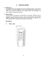
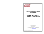
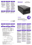
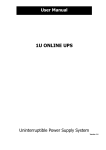
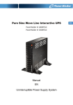
Line Interactive
Pure Sinewave UPS User’s Manual
750/1000VA, 1500/2000VA, 3000VA Series
Uninterruptible Power System
IMPORTANT SAFETY INSTRUCTIONS
SAVE THESE INSTRUCTIONS – This manual contains
important instructions for 750/1000VA, 1500/2000VA,
3000VA series that should be followed during
installation and maintenance of the UPS and batteries.
Please read all safety and operating instructions before
operating the UPS. Adhere to all warnings on the unit
and in this manual. And follow all operating and user
instructions.
CONTENTS
1. INTRODUCTION
1
2. SAFETY INSTRUCTION – CAUTION
2
3. SYSTEM DESCRIPTION
4
4. INSTALLATION
13
5. ADDITIONAL BATTERY INSTALLATION SETUP
23
6. BATTERY REPLACEMENT
28
7. COMMUNICATION PORT
28
8. TROUBLE SHOOTING
29
9. SPECIFICATION
30
10. SOFTWARE INSTALLATION
31
1.
INTRODUCTION
This series is a compact and fully pure sinewave line interactive UPS, and it
designs for critical application and environment, such as desktops, servers,
workstations, and other networking equipments. This model is available in the
output ratings of 750, 1000, 1500, 2000, and 3000VA. This series protects your
sensitive electronic equipments against power problems including power sags,
spike, brownouts, line noise, and blackouts.
This series designs from two-in-one form factor; it can be placed either in Rack
2U or Tower. The front panel of the UPS includes LED indicators and four push
buttons (Power Switch, UPS Test/Silence, Configure, and Enter) that allow to
monitor easily, configuration and control, AC line-in, notification of site wiring fault
and output load status of the UPS. It also includes four LED bar graphic
(Load/Battery Level Indication); two status indications (On AC, On Battery); five
alarm indications (Overload, Over Temperature, Site Wiring Fault, Battery Fault,
Self Test Failure). A push button from the front panel allows silencing of the AC
fail alarm and the initiation of the UPS self test sequence as well. The UPS case
for 750 ~ 2000VA is made of plastic as well as 3000VA is made of metal.
This series is powered from the AC mains and supply AC outputs via receptacles
on the rear panel. Communication and control to the unit is available through
serial or USB ports located on the rear panel. The serial port will support
communications directly with a server. The communications protocol for the serial
ports shall conform to true RS232 interface.
Features:
Microprocessor control guarantees high reliability
High frequency design
Built-in boost and buck AVR
User replaceable design for 1500VA or above
Selectable output range and line sensitive
Cold startup capability
Built-in Dry contact/RS-232/USB communication port
SNMP allows for web-based remote or monitoring management
Enable to extend runtime with scalable external battery pack for
1500VA or above
Overload, Short-circuit, and overheat protection
Rack/Tower 2 in 1 Design
19” rack mount available for all models
1
2. SAFETY INSTRUCTION – CAUTION
IMPORTANT SAFETY INSTRUCTIONS
SAVE THESE INSTRUCTIONS - This Manual Contains Important
Instructions that should be Followed during Installation and
Maintenance of the UPS and Batteries.
WARNING: Do not attempt to repair and service this UPS. This UPS
contains high voltages which could cause the risk of electrical shock.
Even this UPS is disconnected from the electrical outlet, the dangerous
voltage still may be present through the battery. All maintenance and
battery replacement should be performed by qualified service
personnel only.
1. This UPS should be placed indoors with adequate airflow and free of
contamination. To install or operate it in a clean and indoor environment, free
from moisture, flammable liquids, and direct sunlight. Ambient temperature
range must be 0°C to 40°C (32°F to 104°F).
2. This UPS is designed for Commercial/Industrial use only. It is not intended for use
with life support application and other designated “life-critical” devices.
3. Do not remove the input power cord when this UPS is turned on. This removes
the safety ground from this UPS and the equipment connected to the UPS.
4. Turn off this UPS and disconnect input power cord before battery replacement.
5. Battery contains high short-circuit current. Replacing or servicing the battery
which should be performed and supervised by qualified service personnel
knowledgeable of batteries and required precautions.
Remove watches and jewelries
Use tools with insulated handles
Wear rubber gloves and boots.
Do not lay tools or metal parts on top of batteries.
Disconnect charging source prior to connecting or disconnecting battery
terminals.
6. When replacing the batteries, use the appropriate replacement battery kits, same
number and type of battery are MUST.
7. Do not open or mutilate the battery. Released electrolyte is harmful to skin and
eyes that may be toxic.
8. Do not dispose of battery in a fire. Battery may explode. Proper disposal of
battery is required. Please refer to your local laws and regulations for disposal
requirements.
2
2. SAFETY INSTRUCTION – CAUTION
9. To reduce the risk of fire, use only No. 26 AWG or larger telecommunication
line cord.
10. This UPS contains high voltages which may cause the risk of electric shock.
Do not remove cover. There are no user replaceable parts inside this UPS.
Please contact your local dealer or distributor for service.
11. To reduce the risk of fire, connect to a circuit provided with 30 amperes
maximum(for 3000VA)and 20 amperes maximum(for 2000VA and below
models) branch circuit over-current protection in accordance with the
National Electric Code, ANSI/NFPA 70.
12. This pluggable type A equipment with battery already installed by the supplier
is operator installable and may be operated by laymen.
13. During the installation of this equipment it should be assured that the sum of the
leakage currents of the UPS and the connected loads does not exceed 3.5mA.
14. Attention, hazardous through electric shock. Also with disconnection of this
unit from the mains, hazardous voltage still may be accessible through supply
from battery. The battery supply should be therefore disconnected in the plus
and minus pole of the battery when maintenance or service work inside the
UPS is necessary.
15. The mains socket outlet that supplies the UPS shall be installed near the UPS
and shall be easily accessible.
2.1
Description of Commonly Used Symbols
Symbol & Description
Symbol
Description
Alert you to pay special attention
Caution of high voltage
Alternating current source(AC)
Direct current source(DC)
Protective ground
Recycle
Keep UPS in a clear area
3
3. SYSTEM DESCRIPTION
Front Panel —
No.
1
2
3
4
5
6
7
8
9
10
11
12
13
14
Function
Switch
Switch
Switch
Switch
LED
LED
LED
LED
LED
LED
LED
LED
LED
LED
Description
ON/OFF
Self-Test/ Alarm Silence
Config
Enter
Input Type(Operating Mode)
Voltage Range
Bad Battery
Overload
Fault
PSDR Fail (or Site Fault)
Battery Mode
Line Mode
Capacity of Load
Capacity of Battery
1. Power Switch:
- To turn on the UPS, press the
button more than three seconds.
- To turn off the UPS, press and hold this button until you hear the UPS beep
ceases.
2. UPS Test/ Alarm Silence:
- The battery is fully charged during in line mode. To perform self-test
function, press and hold the
button for five seconds.
- To disable alarm buzzer, press this button for a second that will turn off the
4
3. SYSTEM DESCRIPTION
alarm buzzer. Each time a new alarm event is encountered the alarm that will sound
and press this button to turn off the alarm.
Note: Unable to disable alarm buzzer as below conditions: Low
Battery, Overload, Fan Failed, Fan Fault Time Out, Over Temperature.
3. Configure:
To reconfigure the internal UPS setup options, follow the procedure as
below:
Step 1: Press the Configure
button more than three seconds. Then
UPS will transfer from configure mode to “output voltage mode”.
button more than one second, the UPS allows
Step2: Press the Configure
you to select the “output voltage mode” one by one.
Step3: After selecting the mode, press the Enter
button more than three
seconds, the “output voltage mode” is configured.
Step4: UPS will automatically transfer from configure mode to “operating mode”.
button more than one second; the UPS will
Step5: Press the Configure
allow you to select the “operating mode” one by one.
Step6: After selecting the mode, press the
seconds, the “operating mode” is configured.
button more than three
4. Enter:
Press the
button after you choose the mode.
5. Input Type (Operating Mode) LED:
Normal mode: The Yellow LED indicator will illuminate during normal mode,
the UPS accepts AC input voltage range from +/-20%.
Generator: No change to voltage window. However, the low frequency transfer
point is changed to 40Hz and there is no limitation for high frequency transfer
point.
Wide range: The LED indicator will illuminate, the UPS accepts AC input
voltage range from -30% ~ +20%.
5
3. SYSTEM DESCRIPTION
6. Voltage Range (Output Voltage Mode) LED:
UPS Output voltages selection: 110VAC/120VAC/127VAC or
220VAC/230VAC/240VAC.
7. Bad Battery LED:
The LED indicator will light on when the battery is failed or if the battery is
disconnected, LED will flash every two seconds. Please check your battery
connection; replace the battery or contact your local dealer for a battery
replacement kit.
8. Overload LED:
The LED indicator will light on when the UPS overload timeout.
9. Fault LED:
The LED indicator will light on when the UPS fails/overload is timeout /or
short-output.
10. PSDR FAIL LED(or SITE FAULT LED):
PSDR FAIL LED: the LED indicator will light on when the power module of
UPS fails.
SITE FAULT LED: the LED indicator will light on when UPS is plugged into
an improperly utility
Note: “SITE FAULT” function is only available for 120Vac models.
11. BAT Mode LED (Battery Mode):
The LED indicator will flash every five seconds when the UPS is providing battery
power to your equipment. On the other hand, the LED indicator gives you a warning
which will flash every two seconds when the battery is low.
12. Line Mode LED:
The line LED indicator illuminates when the AC source is present.
13. Capacity of Load LED:
LED indicator and the load level indicator will
Load Indicator: The
illuminate to show the load level.
Load Level Indicator:
6
3. SYSTEM DESCRIPTION
There are four LED bar graphic to indicate the percentage of UPS load
capacity which is being used by the protected equipment. The greater
the load, the more LED indicators that will be illuminated. Each LED
indicator designates a 25% of the UPS output capacity. Please see the
following load level respectively.
0 ~ 25%: 1st LED indicator
26% ~ 50%: 1st and 2nd LEDs indicator
51% ~ 75% : 1st, 2nd, and 3rd LEDs indicator
76% ~ 100%: All of four LED indicators will illuminate
14. Capacity of Battery LED:
LED indicator and battery level indicator will
Battery Indicator: The
illuminate to show battery level.
Battery Level Indicator:
There are four LED bar graphic to indicate the amount of battery capacity
remaining. The higher the battery capacity, the more LED indicators that will
be illuminated. Each LED indicator designates a 25% capacity level. Please
see the following capacity level respectively.
0 ~ 25%: 4th LED indicator
26% ~ 50%: 3rd and 4th LEDs indicator
51% ~ 75% 2nd, 3rd, and 4th LEDs indicator
76% ~ 100%: All of four LED indicators will illuminate
Indicator Condition —
Condition
Utility Mode(AC Mode)
Backup Mode(Power Failure)
Site Fault
UPS Fault
Overload
Low Battery
Alarm
Line LED Lighting
Flashing every four seconds
Site fault LED lighting (For 120VAC Models)
4 segment LED bar:
0~25%: 4th LED lighting; 26~50%: 3rd and 4th
LEDs lighting; 51~75%: 2nd, 3rd, and 4th LEDs
lighting; 76~100%: all of 4 LEDs lighting
Fault LED lighting
Overload LED lighting
Battery LED flashing every second
7
Audible Alarm Condition —
Condition
Backup Mode(Power Failure)
Low Battery
UPS Fault
Overload
Battery Replacement
Alarm
Sounding every four seconds
Sounding every second
Continuously Sounding
Sounding every second
Sounding every second
Back Panel -
750/1000VA
Rear panel description for LV and HV models table
No.
Function
LV model (110/120/127Vac)
HV model (220/230/240Vac)
1
Modem/Network Surge Protection
2
RS232 / Dry-Contact Communication Port
3
USB Communication Port
4
5
AC Input Power cord
AC Input & Protection
AC Output NEMA
AC Output IEC
8
3. SYSTEM DESCRIPTION
1500/2000VA
1. Host Rear Panel:
The host rear panel pictures for HV and LV models are shown as below:
Host Rear panel for HV model
Host Rear panel for LV model
9
3. SYSTEM DESCRIPTION
Rear panel description for LV and HV models table
No.
1
2
3
4
5
6
7
8
9
Function
LV model (110/120/127Vac)
HV model (220/230/240Vac)
RS232 / Dry-Contact Communication Port
SNMP Port
USB Port
EPO
Modem/Network Surge Protection
N/A
Input Breaker
AC Output
AC Input
AC Input
External Battery Connector
2. EBM Rear Panel:
The EBM rear panel pictures for HV and LV models are shown as below:
EBM Rear panel for HV model
EBM Rear panel for LV model
10
3. SYSTEM DESCRIPTION
Rear panel description for LV and HV models table
No.
1
2
3
4
5
6
Function
LV model (110/120/127Vac)
HV model (220/230/240Vac)
Battery Output Power Cord
AC Output
External Battery Connector
Output Breaker
N/A
Output Breaker
N/A
Output Receptacles
Output Receptacles
3000VA
Rear panel for HV model
Rear panel for LV model
11
3. SYSTEM DESCRIPTION
Rear panel description for LV and HV models table
No.
Function
LV model (110/120/127Vac)
HV model (220/230/240Vac)
1
Output Breaker
2
AC Output
3
N/A
AC Input
Modem/Network Surge
Modem/Network Surge
Protection
Protection
5
N/A
Input Breaker
6
Input Power Cord
N/A
7
SNMP Slot
SNMP Slot
8
External Battery Connector
External Battery Connector
9
EPO
EPO
10
USB Port
USB Port
11
RS232 / Dry-Contact Communication Port
4
12
4. INSTALLATION
1. Inspecting the Equipment
Inspect the UPS upon receipt. If the UPS has been damaged during
shipment, keep the box and packing material for the carrier. Notify the
carrier and dealer immediately.
2. Placement
This UPS should be installed indoors with adequate airflow and free of
contamination. Locate it in a clean and indoor environment, free from
moisture, flammable liquids, and direct sunlight. Maintain a minimum
clearance of 4 inches (100mm); an ambient temperature range must be 0°C
to 40°C (32°F to 104°F), and operating humidity range must be 20% to 80%
relative humidity (non-condensing).
CAUTION: The long term uses at ambient temperature in higher than 25°C
which should reduce battery life. In addition, place the UPS unit away from the
monitor at least 20cm to avoid interference.
3. Charging
This UPS is shipped from the factory with its internal battery fully charged;
however, some charge may be lost during shipping. The battery should be
recharged prior to use. Plug the UPS into an appropriate power supply and
allow the UPS to charge at least 4 hours.
4. Load Connection
Connect one load-related device to each of the power receptacles supplied at
the rear of the UPS.
5. Modem/Phoneline Connection
Plug incoming telephone line into the “In” socket at the back of the UPS. Use on
telephone line cable and plug one end of the telephone line cable to the “Out”
socket at the back of the UPS. Plug the other end to the modem input socket.
6. DC Start Function
DC Start Function enables UPS to be started up when AC utility power is not
available and battery is full charged. Just simply press the On/Off switch to turn
on the UPS.
7. Turn On/Off
To turn on/off the UPS, you should press the on/off switch three seconds
at least.
13
4.
INSTALLATION
8. UPS Setup
All models series are designed for tower and rack purpose. They can be
installed as a 19 inch equipment rack, and 3000VA can be placed in a
tower (with optional stand) as well. Please follow the instruction for
Tower Setup or Rack-Mount Setup.
9. Tower Setup
This series can be placed in horizontally and vertically. 3000VA model is
designed in a rack itself. As a tower, it is provided with the optional UPS
stand to stabilize the UPS when the UPS is positioned in vertically. The
UPS stand must be attached to the bottom of the tower.
750/1000VA
Tower form
14
4. INSTALLATION
1500/2000VA
Host and EBM integrate into three types of tower forms
(a) Tower form 1
(b) Tower form 2
(c) Tower form 3
15
4.
INSTALLATION
3000VA
Tower form setup
1.
Slide down the UPS vertically and put two UPS stands at the end of
the tower.
2. Place the UPS into two stands carefully.
16
4.
INSTALLATION
10. Rack-Mount Setup
750/1000/1500/2000VA(optional) and 3000VA can be installed in 19”
racks. And the UPS and external battery enclosure need 2U of valuable
rack space. Use the following procedure to install UPS in a rack.
750/1000VA(optional)
1. Align the mounting ears with screw holes on the side of the UPS.
2.
Install rack-mounting rails with the screws provided tightened up
into rack enclosure.
17
4. INSTALLATION
3. Insert UPS into the slide assemblies and lock it in the rack enclosure.
4.
Add up the front panels for both sides. The load can be connected.
18
4. INSTALLATION
1500/2000VA(optional)
HOST and EBM integrate into a rack form
1. Place the UPS on a flat and in a clean place that the front side of the
UPS is facing to you.
2. Disconnect the cable from the Host and EBM.
HOST and the EBM are disconnected
3. Loosen the screws and remove the Host and EBM cover from the unit
4.
Pull two covers toward the direction shown as below.
19
4.
5.
6.
INSTALLATION
Align the mounting bracket with the screw holes on the each side of
Host and EBM and secure with the supplied screws.
Reinstall the Host and EBM cover.
7. Tighten all screws up to front panels and setup rack-mount for front
side is completed
8.
Align two small mounting brackets at the rear of Host and EBM and
secure with the supplied screws. Install Output receptacles at the
rear panel of the Host.
20
4. INSTALLATION
9.
Setup rack-mount is completed and to connect the UPS
EBM and EBM integrate a rack form
Remark : The rackmount kit for connecting the Host-to-EBM & EBM-to-EBM is
different. Please contact your dealer for further details.
3000VA
Install the 3000VA series into 19” rack as shown below.
9.
10.
Turn on the UPS and connect the load.
After installing the UPS into rack, the load may be connected. Make
sure the load equipment is turned off, then plug all loads into the output
receptacle properly protected by a circuit breaker of fuse in accordance
with national and local electrical codes.
21
4. INSTALLATION
10.
Emergency Power Off(EPO) set up
1500/2000VA and 3000VA include EPO port that allows power to be shut
down the protected equipment immediately and does not follow the
shutdown procedure from any power management software.
Note: When EPO switch is reset, the equipment will not return to battery
power until the UPS is manually restarted. If pressing power switch to
turn off UPS after EPO is activated, the UPS remains in Standby mode
when restarted until pressing power switch to turn on the UPS again.
Follow the procedure to install the EPO switch as below.
1.
2.
3.
4.
5.
6.
7.
8.
5.
Check the UPS is turned off.
Remove the EPO connector from the EPO port on the rear panel of
UPS
Connect isolated, normally-open, dry contacts (rated to handle 60Vdc
maximum, 30Vac RMS maximum, and 20mA maximum) across the
EPO device to Pin 1 and Pin 2. Use non-shield wiring, size 18-22
AWG (0.75 mm2 – 0.3 mm2).
Reconnect the EPO connector to the EPO port.
Verify that the externally-connected EPO switch is not activated to enable
power to the UPS output receptacles.
Plug in the UPS, then pressing power switch
button to turn on the
UPS.
Activate the external EPO switch to test the EPO function
De-activate the external EPO switch and restart the UPS.
ADDITIONAL BATTERY INSTALLATION SETUP
1500/2000VA and 3000VA include external battery port that allow to provide
additional battery runtime. 1500/2000VA model has no internal battery,and
3000VA has designed an internal battery inside the UPS.
Caution: Connecting battery cable to external battery port may occur
sparkle if adding up additional battery.
Follow the procedure to install additional battery as below.
22
5.
ADDITIONAL BATTERY INSTALLATION SETUP
1500/2000VA
There are two external battery ports for each side of UPS itself and battery
pack.
1. Connect the battery cable to the external battery port of the rear of UPS.
2. Then connect the supplied battery cable from extended battery module
to the external battery port of the rear of previous UPS.
3. If continuing to add up extended battery pack, repeat above steps.
Additional battery connection in rack form
Additional battery connection in tower form
3000VA
There is one external battery port for the UPS itself.
1.
2.
Connect the supplied battery module cable from extended battery module
to the external battery port of the rear of UPS.
If continuing to add up extended battery module, repeat above steps.
23
6. BATTERY REPLACEMENT
When the Bad Battery
indicator flashes and there is a
continuous sounding, the battery may need to be replaced. Please check
the battery connection or contact your local dealer to order new battery.
CAUTION: A battery can present a risk of electrical shock and high short
circuit current. The following precautions should be observed before
replacing the batteries.
1.
2.
3.
4.
Turn off the UPS and disconnect the utility power cord from the wall outlet.
Remove rings, watches, and other metal objects.
If the battery replacement kit is damaged in anyway or shows signs of
leakage, contact your dealer immediately.
Properly recycle or dispose of used battery. Do not dispose of batteries
in a fire. The batteries may explode.
Note: If you are not qualified service personnel to replace the battery, do
not attempt to open the battery door. Please call local dealer or
distributor immediately.
Recycle the used battery:
Never dispose the batteries in a fire. It may explode.
Do not open or mutilate the batteries. Released electrolyte is
harmful to the skins and eyes. It may be toxic. A battery can present a
risk of electrical shock and high short circuit current.
To recycle properly the used battery, please do not discard the UPS, battery
pack, and batteries into the trash bin. Please follow your local laws and
regulations; you may contact your local recycling waste center for further
information to dispose properly of the used UPS, battery pack, and
batteries.
Follow the steps and Charts below to replace batteries:
750/1000VA
1.
Unscrew and remove the front panel on both ends.
24
6. BATTERY REPLACEMENT
2. Disconnect the battery cable from the UPS and remove the battery
retaining battery bracket.
3. Grasp the battery and pull it out from the front panel.
4.
5.
6.
Slide the new battery into UPS
Reconnect the battery cable and screw up the battery retaining battery
bracket.
Close and reinstall the front panel.
1500/2000VA
1. Remove the battery case (EBM) front panel by pulling on both ends.
25
6. BATTERY REPLACEMENT
2. Disconnect the battery cable from the EBM.
3. Unscrew and remove the battery retaining battery bracket.
4.
Pull the battery out onto a flat area.
5.
6.
Slide the new battery into EBM.
Reconnect the battery cable and screw up the battery retaining
bracket.
Close and reinstall the front panel back to EBM.
7.
26
6. BATTERY REPLACEMENT
3000VA
1.
Remove the battery case (EBM) front panel by pulling on both ends.
2.
Disconnect the battery cable from UPS.
3. Unscrew the battery bracket from the EBM
4. Remove the battery bracket from EBM by pulling on both ends.
5. Pull the battery out (from right side) onto flat area.
27
6. BATTERY REPLACEMENT
6. Pull the left side of battery out onto flat area.
7. Slide the new batteries into EBM.
8. Reconnect the battery cable and screw up the battery bracket.
9. Close and reinstall the front panel back to EBM.
7. COMMUNICATION PORT
7.1
RS232 + Dry contact (750/1000/1500/2000/3000VA):
DB9 Female (RS232 +dry contact)
7.2
PIN #
1
Description
Low
Battery
I/O
Output
2
3
4
5
6
7
8
TxD
RxD
DTR
Common
DSR
RTS
AC Fail
Output
Input
Input
-Output
Input
Output
Function Explanation
Low Battery Output
(*normally open, pull to
Pin#5 when battery low
alarm in battery mode)
TxD
RxD
(tied to pin 6)
Common (tied to chassis)
(tied to pin 4)
No connection
AC Fail Output
(*normally open, pull to
Pin#5 when UPS is in
battery mode).
USB port: HID protocol
The USB and RS232 are unable to operate at the same time. Either only USB or
DB9 can connect with RS-232 at one time, usually connecting with USB function is
priority.
28
8.
TROUBLE SHOOTING
Audible Alarm Trouble Shooting:
Problem
Sounding every 4
seconds
Sounding every second
Cause
The UPS is on battery
Solution
Check the input voltage
The battery is running low
Continuously sounding
The UPS fails
Sounding every second
Output overload
Continuously sounding
Battery may need to charge
or service
Save your work and turn off
your equipment
Please contact your local
dealer
Check load level indicator
and remove some load
Replace the battery
General Trouble Shooting:
Problem
Cause
The UPS is not on
The power cord is not
when power switch is connected correctly
pressed
The wall outlet may be faulty
UPS could not
provide power to the
load
Battery has reduced
backup time
.
The UPS fault LED
lights on
Solution
Check the power cord connection
Please contact your local qualified
electrician
The UPS output may
1. Disconnect all loads and ensure
short-circuit or overload
nothing is lodged in output
receptacles
2. Ensure loads are not detective or
shorted internally
Internal fuse may be blown
Please contact your local dealer
Power presents on one output Check the output fuse
receptacle
No output from any output
1. Check the connected cable
receptacle
2. Ensure the load does not
exceed the maximum rating of
UPS
Battery is not charged
Re-charge the battery at least 24
hours
Battery may not able to hold a 1. Recharge the battery at least 8
full charge due to age.
hours
2. Replace Battery
The UPS fails
Save your work and turn off
equipment. Please contact your
local dealer
The UPS may be over- loaded Check the load status
The UPS may be failed
Please contact your local dealer
Connected
equipment’s lose
power while
connected to the UPS
The UPS is beeping The UPS is in fault condition
continuously
Buttons does not
1. The UPS is in green
work
mode
2. Button is Broken
29
Check the audible alarms condition
table
1. Wait for a while and try again
2. Please contact your local
dealer
9.
MODEL
CAPACITY
Watt
INPUT
Voltage
Voltage
Range
OUTPUT
SPECIFICATION
750/1000VA
1500/2000VA
2880VA
500W/700W
975W/1300W
2100W
110/120/127VAC or 220/230/240VAC
Acceptable
Voltage Range
Line Low
Transfer(Wide
mode)
Line High
Transfer
0-160VAC
77/84/89VAC ± 4% or 154/161/168VAC ± 4%
132/144/152VAC ± 4% or 264/276/288VAC ± 4%
Frequency Range
Surge Rating ( LV/HV )
320 / 230 Joules
Voltage
50Hz or 60Hz
±0.1Hz
Waveform
Battery Mode
Typical
Battery Type*
Battery Number
Pure Sinewave
110% -0%, +8%; shutdown after 3 minutes. 150% -0%,
+10%; shutdown after 10 cycles
110% ± 6%; shutdown after 30 seconds. 120 % ± 6 %;
Shutdown after 5 cycles
2-4ms Typical, 6 ms max ; 13ms max. for generator
mode
12V/7AH ;
12V/7Ah; 12V/9Ah
12V/5Ah
12V/9Ah
2 pcs
Backup Time (at full load)
Recharge Time
500 / 640 Joules
±5% RMS for entire battery voltage range
Frequency Regulation
(Batt. Mode)
Line Mode
430 / 250 Joules
110/120/127VAC or 220/230/240VAC
Frequency
TRANSFER
TIME
BATTERY
0-300VAC
50/60Hz ±5Hz for Normal Mode; >40Hz for Generator
Mode
Voltage Regulation (Batt.
Mode)
OVERLOAD
RATING
/
4pcs
8 pcs
5 minutes min.
4 hours to 90%
after discharged
30
3 hours to 90% after discharged
750/1000VA
MODEL
AC Mode
1500/2000VA
2880VA
Line LED lighting
Backup Mode
Site Fault
Battery LED flashing every 4 seconds
Site fault LED lighting (for 120Vac models)
th
INDICATORS
Load/Battery Level
4-segment LED bar – 0 - 25%: 4 LED lighting;
rd
th
26% - 50%: 3 and 4 LEDs lighting; 51%-75%: 2nd,
3rd, and 4th LEDs lighting
76% - 100%: 4 LEDs in a row all lighting
UPS Fault
Fault LED lighting
Overload
Overload LED lighting
Low Battery
AUDIBLE
ALARM
Battery LED flashing every second
Backup Mode
Sounding every 4seconds
Low Battery
Sounding every seconds
UPS Fault
Continuously Sounding
Overload
Sounding every second
Battery Replacement
PHYSICAL
UPS Case
Dimension
(WxHxD) mm
235*86.2*383
217*86.5*413.5
438*86.2*582
750VA: 10.6/
1000VA: 10.7
6.5
34.1
Dimension
(WxHxD) mm
N/A
217*86.5*413.5
438*86.2*582
Net weight (kg)
N/A
11.5
41.1
Net weight (kg)
Battery
Case
ENVIRONMENT
Sounding every second
Operating Environment
0- 40°C, 0-90 % relative humidity (non-condensing)
Noise Level
INTERFACE
Less than 45dB
RS-232
Support Windows Family, Linux, and Mac
Dry-Contact
Yes
Yes
Yes
USB
Yes
Yes
Yes
SNMP
N/A
Optional
Optional
EPO
N/A
Yes
Yes
31
10.
SOFTWARE INSTALLATION
WinPower is a brand new UPS monitoring software, which provides user-friendly
interface to monitor and control your UPS. This unique software provides safely
auto shutdown for multi-computer systems while power failure. With this software,
users can monitor and control any UPS on the same LAN no matter how far from
the UPSs.
Installation procedure:
1.
Go to the website: http://www.ups-software-download.com/winpower.htm
2.
Choose the operation system you need and follow the instruction described
on the website to download the software.
3.
When downloading all required files from the internet, enter the serial No:
511C1-01220-0100-478DF2A to install the software.
When your computer restarts, the WinPower software will appear as a green plug
icon located in the system tray, near the clock.
32
33