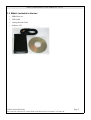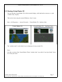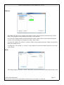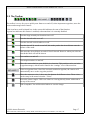
1
Aurora Virtual Radar 3D
User Guide
Doc Ref
Edition
Ver 1.0.0.2
Edition Date
06/11/10
Status
This User Guide is regularly updated with additional
information.
You can find the latest version at :http://www.auroraeurotech.com/avionics/download.php
Aurora Virtual Radar 3D User Manual Ver 1.0.0.2
This product complies with relevant standards for CE marking in the European Union.
.
PRECAUTIONS
* NEVER
Use the Virtual Radar 3D where it is illegal.
* NEVER
Expose the receiver to liquids, rain or snow.
* AVOID
Using the supplied antenna on a vehicle when it is moving. As it may become dislodged.
* AVOID
Placing the SSRx in direct sun light or expose to extremes of temperature.
Special thanks to the following for giving us permission to use their Icons / Outlines / Silhouettes
etc.
Bones
- http://www.homepages.mcb.net/bones/index.htm
Ian Kirby - http://www.sbsbst.co.uk/iank
(c)2010 Aurora Eurotech
Aurora Eurotech, Beech House, Grasby Road, North Kelsey Moor, Lincolnshire, LN7 6HJ, UK
Page 2
Aurora Virtual Radar 3D User Manual Ver 1.0.0.2
Table of Contents
1 Welcome...................................................................................................................................................4
1.1 Features of your Virtual Radar 3D...................................................................................................4
1.2 Min PC Specification......................................................................................................................4
1.3 What's included in the box...............................................................................................................5
2 Getting Started.........................................................................................................................................6
2.1 Installation........................................................................................................................................6
2.2 Starting Virtual Radar 3D.................................................................................................................7
2.3 About the SSRx Receiver.................................................................................................................8
2.4 Antenna.............................................................................................................................................9
3 Radar Screen............................................................................................................................................9
3.1 Main Menu.......................................................................................................................................9
3.2 The Toolbar....................................................................................................................................17
3.3 Earth View......................................................................................................................................18
3.4 Aircraft List....................................................................................................................................20
3.5 Aircraft Images...............................................................................................................................20
3.6 Mode A/C List................................................................................................................................21
3.7 Reporter .........................................................................................................................................21
4 Internet Sharing......................................................................................................................................22
5 Advanced Information...........................................................................................................................23
5.1 SQLite Database.............................................................................................................................23
6 Troubleshooting.....................................................................................................................................24
7 COAA Planeplotter Lite.........................................................................................................................25
7.1 Getting Started................................................................................................................................25
7.2 Finding Planeplotter information and help.....................................................................................26
(c)2010 Aurora Eurotech
Aurora Eurotech, Beech House, Grasby Road, North Kelsey Moor, Lincolnshire, LN7 6HJ, UK
Page 3
Aurora Virtual Radar 3D User Manual Ver 1.0.0.2
1 Welcome
1.1 Features of your Virtual Radar 3D
•
Real Time 3D view of Mode-S/ADS-B tracked aircraft.
•
Display Mode-A/C Codes.
•
Aircraft Proximity Alert LED.
•
NASA Maps.
•
Aircraft Alerts.
•
Photos of tracked aircraft.
•
Support for dual monitors.
•
Live Internet sharing.
•
Screen capture button.
•
Automatic FTP upload of screen shots.
•
Includes COAA Planeplotter Lite.
•
Supports COAA Planeplotter MLat, (Fully approved Ground Station) .
•
Receiver outputs decoded messages with aircraft data. ie Hex,Alt,Lat,Lon etc.
•
Raw data directly from receiver, Time stamped to 25ns (using 64 Bit timer).
•
Compatible with third party applications, via port 30003.
•
Uses SQLite open source database engine.
•
SSRx Receiver uses advanced signal processing. (12bit 40Mhz ADC,FPGA and dedicated DSP)
•
Size only 130mm x 81mm x 30mm.
•
No external power supply required.
•
Connects to Windows PC, Laptop, via Plug & play USB connection.
1.2 Min PC Specification
We would recommend Pentium 4 / RAM 512MB / Hard Disk 1GB free / DVD Drive or better
with Windows XP / Vista / Windows 7.
As with other 3D software (ie Flight Simulators / Games / Google Earth) a modern graphics card
is recommended.
Planeplotter Lite will run on a lower specification PC and is included with the Virtual Radar 3D
CD.
(c)2010 Aurora Eurotech
Aurora Eurotech, Beech House, Grasby Road, North Kelsey Moor, Lincolnshire, LN7 6HJ, UK
Page 4
Aurora Virtual Radar 3D User Manual Ver 1.0.0.2
1.3 What's included in the box
•
SSRx Receiver.
•
USB Cable.
•
Getting Started Guide.
•
Software CD
(c)2010 Aurora Eurotech
Aurora Eurotech, Beech House, Grasby Road, North Kelsey Moor, Lincolnshire, LN7 6HJ, UK
Page 5
Aurora Virtual Radar 3D User Manual Ver 1.0.0.2
2 Getting Started
2.1 Installation
Close all other applications before installing.
Plug the SSRx into your computer, then wait for a minute while the drivers are automatically
installed (if they are not already installed).
After inserting the CD, the autoplay box will appear.
Select “Show Virtual Radar 3D Launcher.”
When the box appears, click on Install. Set-up wizard will appear. Follow wizards instructions.
If autoplay is not enabled, double-click on My computer and then double-click on your DVD drive
icon to launch installer. Follow installation instructions.
If the program does not begin installing automatically, right click on your CD/DVD drive icon in
My computer and choose “Explore” from the drop down menu.
Double-click on ”autorun.exe” to run the launcher.
Then follow the on screen instructions.
(c)2010 Aurora Eurotech
Aurora Eurotech, Beech House, Grasby Road, North Kelsey Moor, Lincolnshire, LN7 6HJ, UK
Page 6
Aurora Virtual Radar 3D User Manual Ver 1.0.0.2
2.2 Starting Virtual Radar 3D
You can start the Virtual Radar 3D with its normal display; with land and sea textures; or with
“outlines only” display.
This can be done using the normal Windows “Start” menu.
Start ->All Programs -> Aurora Eurotech → Virtual Radar 3D – Outlines Only.
Virtual Radar 3D
Virtual Radar 3D – Outlines Only.
.
The “outlines only” is also ideal for use on laptop or lower powerd PCs.
Note:On older versions of the Virtual Radar 3D the “Outline Only” was called “Low Spec Mode” these
are exactly the same.
(c)2010 Aurora Eurotech
Aurora Eurotech, Beech House, Grasby Road, North Kelsey Moor, Lincolnshire, LN7 6HJ, UK
Page 7
Aurora Virtual Radar 3D User Manual Ver 1.0.0.2
2.3 About the SSRx Receiver
The SSRx receiver is a small black metal box with two connectors on the back.
Blue LED
Red LED
Orange LED
Yellow LED
Data
Green LED
Aircraft proximity
alert
Mode-S Data
Received
Mode-A/C Data
Received
USB Connected
Indicates that an
aircraft with ANY
type of transponder
(Mode A/C or Mode
S) is close.
This is data from a
modern transponder
and may contain
aircraft position
information.
This data is from
This is general Indicates the
older type
data being
USB is connected
transponder and only received.
supplies Squawk code
or Altitude.
Note:- If you are using a pre-amp the the blue LED will light up for aircrafts some distance away as well
as close aircrafts.
USB Computer SMA Antenna
(c)2010 Aurora Eurotech
Aurora Eurotech, Beech House, Grasby Road, North Kelsey Moor, Lincolnshire, LN7 6HJ, UK
Page 8
Aurora Virtual Radar 3D User Manual Ver 1.0.0.2
2.4 Antenna
Depending on which antenna you have (supplied with your Virtual Radar 3D, or one you have
purchased separately) the following advice will be helpful.
Mag-mount Antenna
The mag-mount antenna is designed to operate best when used on either the metal roof of a car or
attached to a metal plate (a sweet or biscuit tin lid could be ideal).
For the best range locate the antenna in a place that will have a clear view of the sky.
Most Mag-Mount antennas are not designed to be permanently mounted outside.
External Antenna
For the best possible range we would recommend an external antenna, mounted as high as possible
and using low loss coax cable.
There are links to suitable suppliers on our website.
http://www.auroraeurotech.com/avionics/order.php
3 Radar Screen
Most of the windows can be toggled on and off using the 'windows' menu.
They are freely dockable which can be done by grabbing the handle at the top and pulling away
until it is detached.
The window can re-docked by hovering it over the main window until a blue shadow appears, let
go of the window and it will reappear inside the main window.
Hold the Ctrl button on the keyboard and drop the window to stop it recombining and instead
hover over the main window.
3.1 Main Menu
File
Backup Database
Will make a backup copy of the current database that holds all the data for aircraft you have seen
and related information about their flights.
You will be told where you can find your backed up database.
(c)2010 Aurora Eurotech
Aurora Eurotech, Beech House, Grasby Road, North Kelsey Moor, Lincolnshire, LN7 6HJ, UK
Page 9
Aurora Virtual Radar 3D User Manual Ver 1.0.0.2
Reset Windows Positions
In rare circumstances where you may find one of your windows is not visible.
This could happen if you switch from a multi monitor configuration to a single monitor and have
not remembered to bring all the windows back into view.
This will reset all the undockable windows back into the original positions.
Take Screenshot
Will take a snapshot of the screen, you will then be prompted where to save the image file.
Upload Screenshots
Will tell the program to upload an image of the current view to a web server.
You can upload a single image or it can automaticly upload at preset time intervals.
Exit
Will close the Virtual Radar 3D.
Views
Save Views
Windows
Toggle Mode-S List
Display or hide the Mode-S list.
Toggle Mode-AC List
Display or hide the Mode-A/C List
Toggle Radar Window
Display or hide the Radar Window.
Toggle Reporter Window
Display or hide the Reporter Window.
Toggle Aircraft Information Window
Display or hide the Aircraft Information Window
Toggle Debuging Log Window
Display or hide the Debugging Window.
(c)2010 Aurora Eurotech
Aurora Eurotech, Beech House, Grasby Road, North Kelsey Moor, Lincolnshire, LN7 6HJ, UK
Page 10
Aurora Virtual Radar 3D User Manual Ver 1.0.0.2
Settings
Display
The Display settings configuration dialog allows you to set most of the colours for Aircraft /
Airports etc.
Aircraft Marker is the small symbol use to indicate the position of the aircraft on the Radar view.
Data
Most of this dialog is self explanatory.
Aircraft labels.
There are special characters for the aircraft information that will be inserted into the label.
Below is a list of special characters along with their respective functions.
#i
Will insert 'Callsign' unless this is empty, #l
otherwise it will use 'Hex'
Will insert 'Latitude'
#I
Will insert 'Registration' unless this is
empty, otherwise it will insert 'Hex'
Will insert 'Longitude'
#L
(c)2010 Aurora Eurotech
Aurora Eurotech, Beech House, Grasby Road, North Kelsey Moor, Lincolnshire, LN7 6HJ, UK
Page 11
Aurora Virtual Radar 3D User Manual Ver 1.0.0.2
#a
Will insert 'Altitude'
#m Will insert 'Manufacturer'
#c
Will insert 'Callsign'
#o
Will insert 'Operator Name'
#C Will insert 'Country'
#r
Will insert 'Registration'
#s
Will insert 'First Seen' time
#q
Will insert 'Sqawk'
#S Will insert 'Last Seen' time
#t
Will insert 'Track'
#g
Will insert 'Ground Speed'
#T
Will insert 'ICAO Type Code'
#h
Will insert 'Hex'
#!
Will add brackets around the text e.g. #!g = “(200 kts)” rather than “200 kts”
#^
Will show only the core value itself e.g. 'kts' 'ft' etc. will be left out.
You can also use modifiers with these, they will only act if there is some text to write e.g. Not
empty. They can be used can be used as follows to provide a result as shown. #!g for example
will insert “(200 kts)” rather than “200kts”.
Airports
Enable / Disable the airport markers for individual countries.
(c)2010 Aurora Eurotech
Aurora Eurotech, Beech House, Grasby Road, North Kelsey Moor, Lincolnshire, LN7 6HJ, UK
Page 12
Aurora Virtual Radar 3D User Manual Ver 1.0.0.2
Outlines
All outline files that can be found in the outlines folder in the programs install directory will be
listed. The program can load outline files with a .out extension.
As well as the default outlines included with the software many others can be found on internet
resource sites including ones designed for other virtual radars.
Just place the outline files into the “outlines” folder in the program directory which you specified
during the install process.
To change the “Line width” or “Colour” of the outline first select the outline in the box to the left
of the dialog.
Alerts
This dialog displays all active “Alerts” and allows selection of the action when that aircraft is seen.
(c)2010 Aurora Eurotech
Aurora Eurotech, Beech House, Grasby Road, North Kelsey Moor, Lincolnshire, LN7 6HJ, UK
Page 13
Aurora Virtual Radar 3D User Manual Ver 1.0.0.2
Alerts can be configured manually by entering their hex code in the box at the left of the dialog.
Alerts can also be automatically configured by right clicking in either the radar window or the
aircraft list and selecting the “Toggle alert” button.
Play Sounds will cause the selected sound file to play when an aircraft triggers an alert.
Show overlay will cause a transparent overlay to appear on top of any current programs when an
alert is triggered.
Flash task bar will cause the program to be highlighted and flash in the task bar attracting your
attention.
Location Manager
Locations appear on the map with the optional rings and allow you to display the distance between
you and the aircraft, they also act as markers for other important places you may want to
remember.
To add a new location select the new location button, a new location will be created that you can
fill in information about. You may also disable others so they wont be shown but will still be saved
for later.
“Receiver Location” tick box sets the location that the default view button in the toolbar will
return you to and also allows the receiver to work in “Fixed Site” Mode, which may enable your
receiver to pick up aircraft with a weaker signal.
(c)2010 Aurora Eurotech
Aurora Eurotech, Beech House, Grasby Road, North Kelsey Moor, Lincolnshire, LN7 6HJ, UK
Page 14
Aurora Virtual Radar 3D User Manual Ver 1.0.0.2
You will also see a section for adding and removing rings, these are the rings you see around the
locations you set.
Receiver Mode
The receiver has 2 modes of operation :
Fixed Site recommended when the receiver is used at a location where the Latitude/Londitude is
known.
Mobile recommended for use when the location of the receiver is not known, or when the receiver
is moving.
Help
Aurora Website
Open Aurora Eurotech website in your web brouser.
Software Status
Check your current version numbers, and any other important information.
You can also go to our Download Center from this page.
Check for Updates
Will check if there are new updates available.
Manual
Open this user manual in Adobe Acrobat Reader.
(c)2010 Aurora Eurotech
Aurora Eurotech, Beech House, Grasby Road, North Kelsey Moor, Lincolnshire, LN7 6HJ, UK
Page 15
Aurora Virtual Radar 3D User Manual Ver 1.0.0.2
Release Notes
Display release notes for this software.
System Report
This funcion is to help us diagnose any problems, you can normaly ignore this option.
About
Display version information for both your Virtual Radar 3D software and your SSRx Receiver.
(c)2010 Aurora Eurotech
Aurora Eurotech, Beech House, Grasby Road, North Kelsey Moor, Lincolnshire, LN7 6HJ, UK
Page 16
Aurora Virtual Radar 3D User Manual Ver 1.0.0.2
3.2 The Toolbar
The toolbar is a way for you to quickly turn features on and off, select important waypoints, move the
camera and manage other features.
If the icon has a small coloured box in the corner this indicates the state of the function.
A green box indicates this feature is enabled, red means that it is currently disabled.
Turn the rings around your locations on or off.
Turn the aircraft trails on or off.
Turn the aircraft vertical stalks on or off.
Turn the aircraft 2d mode on and off, this mode pushes the aircraft down onto the
surface of the earth.
This turns the aircraft labels on and off for all aircraft. However when you select an
aircraft the label will still be shown.
Turn outlines on and off.
Turn airport markers on and off.
Move the camera back to your default view location. This position can be set in the
waypoint manager, which can be found in the “settings” area of the menu bar..
Select a waypoint from a list of the currently enabled waypoints, the camera will
automatically move to the waypoint position.
Move the camera to view 1, there are also buttons for different views. These views
can be setup in the menu bar under “Views”
Resets the camera angles. Will reset it back to viewing directly down with north at
the top of the screen.
Take a snapshot. You will be asked where to save the image.
(c)2010 Aurora Eurotech
Aurora Eurotech, Beech House, Grasby Road, North Kelsey Moor, Lincolnshire, LN7 6HJ, UK
Page 17
Aurora Virtual Radar 3D User Manual Ver 1.0.0.2
3.3 Earth View
Aircraft are positioned on a globe of the world and the camera can be zoomed and rotated around
to allow a very dynamic and informative way of viewing what is happening in the skies above you.
Moving around is done by left clicking on the ground and dragging the mouse, you will see the
world move to keep the piece of ground under your mouse cursor. (The arrow keys can also be
used).
Zooming in and out of the map is done by using the scroll wheel or the PageUp/PageDown keys.
You can also rotate and tilt the camera by either using either the Mouse scroll wheel button or the
shift + left mouse button.
The compass in the top right of the screen will help you tell which direction the camera is
pointing.
The “R” button on the tool bar can be used at any time to point the camara directly downwards.
To select aircraft, double left click on the ground where the aircraft is.
The aircraft will be selected and you will see it change colour, it will also be highlighted in the list
of aircraft.
More options are accessed by right clicking. Currently you can set the view to tracking mode or
add an alert for the aircraft.
By clicking tracking, the camera will hover over the top of the aircraft and follow the aircraft as it
moves.
(c)2010 Aurora Eurotech
Aurora Eurotech, Beech House, Grasby Road, North Kelsey Moor, Lincolnshire, LN7 6HJ, UK
Page 18
Aurora Virtual Radar 3D User Manual Ver 1.0.0.2
If you add an alert the program will highlight the aircraft in the list and notify you when it is seen
in future.
Colours and other viewing settings can be modified in the “Display settings” found under
“Settings” in the menu bar.
Keyboard Shortcuts
Arrow Keys
Move the camera North/South/East/West
Shift + Left
Mouse
Rotate and tilt the camera
Page Up
Zoom in
Page Down
Zoom out
R
Reload outline files
(c)2010 Aurora Eurotech
Aurora Eurotech, Beech House, Grasby Road, North Kelsey Moor, Lincolnshire, LN7 6HJ, UK
Page 19
Aurora Virtual Radar 3D User Manual Ver 1.0.0.2
3.4 Aircraft List
Est Distance
This column gives an estimate of the distance to an aircraft using only the signal strength to
calculate its distance.
Our Virtual Radar Receiver is optimised for measuring how far an aircraft is from the receiver, so
you have an estimated distance for every aircraft in your Aircraft List.
This opens up many possibilities, see examples below.
a) You see an aircraft outside that you cannot identify but on the virtual radar there is only one
displaying V Close * so you know exactly which aircraft it is.
b) You know that the Vulcan or BBMF aircraft is on your Aircraft List but now you can see if it is
about to fly overhead or if it is flying around 100 miles away.
Note:- If you are using a pre-amp then aircrafts will appear closer.
3.5 Aircraft Images
The aircraft information window displays the images of aircraft you have selected.
This feature uses airliners.net to search for images of any aircraft with a known registration.
By clicking on either the images or the text your internet browser will be launched and you can
then search through even more images of the aircraft you are interested in.
(c)2010 Aurora Eurotech
Aurora Eurotech, Beech House, Grasby Road, North Kelsey Moor, Lincolnshire, LN7 6HJ, UK
Page 20
Aurora Virtual Radar 3D User Manual Ver 1.0.0.2
3.6 Mode A/C List
Mode-A/C messages from aircraft can contain either squawk (Mode A) or altitude (Mode C).
It should be noted that there is no way of knowing which type of message type is being sent or the
position of the aircraft.
We also only display codes from aircraft close to the SSRx Receiver.
Information available from our receiver :1/ Squawk code. From this you can determine who is controlling the aircraft.
i.e. squawk 6171 to 6177 indicates the aircraft is under the control of
Doncaster Sheffield Approach
There will also be a number of Mode C codes, these are of no significant use.
2/ Estimated distance to aircraft.
Just like listening to pilots, Mode-A/C helps build up a mental picture of what is going on above
our heads but it wont add any more trails to our screen.
For users in the UK the document “ENR 1.6 · ATS Surveillance Services and Procedures” is
available at http://www.nats-uk.ead-it.com and contains information about how squawk code are
allocated.
Similar documents are available for other countries.
3.7 Reporter
More advanced users may want to view information about the history of an aircraft.
This may be done by using the reporter. You can make this window appear by clicking “Toggle
Reporter Window” found in “Windows” in the menu bar.
The reporter queries the database file of the program for the information you require, it will return
the first 1000 records for any query you request, all of which can be sorted by clicking the heading
label.
(c)2010 Aurora Eurotech
Aurora Eurotech, Beech House, Grasby Road, North Kelsey Moor, Lincolnshire, LN7 6HJ, UK
Page 21
Aurora Virtual Radar 3D User Manual Ver 1.0.0.2
The reporter is also partially undockable, if you grab one of the tabs you may pull it out and
rearrange it inside the main reporter window.
This allows you to see more information at once. An example of this would be if you select an
aircraft; you will be shown a list of the flights that it was seen on.
To search for something, pick the column that identifies the feature. For instance “Registration”,
then click the way to compare it. Change this from the default “Match Anything” to “Begins with”
and type “United”.
As you type the selection is filtered down until only aircraft starting with that word are visible.
Most of the comparators are self explanatory. However there is one that may be useful to do a
more advanced search.
This operator is called “Similar to” and allows wild cards. The wild cards are _ and %.
_ is used to match any single character. For example a_c could match abc or a1c.
% is used to match any number of characters. For example a%c could match abc, or abbbc.
4 Internet Sharing
This feature introduces internet sharing with www.radarvirtuel.com
Please Note:This is an experimental feature to test both our software and the
network sharing server.
We have designed the internet sharing feature to be true sharing. Virtual radar users can share their
aircraft positions with an aircraft tracking website (radarvirtuel.com) and the website will share its
aircraft positions with the virtual radar user.
You DO NOT need to make any changes to your router or firewall.
By default the sharing is turned OFF and you must turn it ON when you start the Virtual Radar 3D
software.
Please Note:-
(c)2010 Aurora Eurotech
Aurora Eurotech, Beech House, Grasby Road, North Kelsey Moor, Lincolnshire, LN7 6HJ, UK
Page 22
Aurora Virtual Radar 3D User Manual Ver 1.0.0.2
* There will be times when the sharing server will be unavailable.
* We expect there to be issues of some type with this software (it is experimental).
•
The main areas of the software we are working on at present are: the handover of aircraft
between locally received aircraft and network aircraft and the Aircraft List, as it can have 2,300
aircraft at any time.
•
Aircraft at the edge of your receivers reception may appear as 2 separate aircraft, one for your
locally received aircraft the second a network aircraft.
At present we display both aircraft positions, in future versions of this software, we will look to
improve this aircraft handover.
5 Advanced Information
5.1 SQLite Database
The method the Virtual Radar 3D Software uses to find information about an aircraft is described
here.
When the receiver first sees an aircraft it looks at the hex code and uses the 'Countries.csv' file that
is found in the 'hex' folder in your install directory to find the correct country image which it will
then load from the 'flags' folder within the 'hex' folder.
Next it uses the hex again and queries the DataSQL.sqb to find out its Registration, Manufacturer
and ICAO type code.
If it finds an entry it will look in the 'types' folder within the 'hex' folder to find a bitmap file (bmp)
with the name the same as the ICAO type code. If it finds one it will load the aircraft silhouette.
Finally the first callsign is used to lookup the operator of aircraft, it does this by searching the
'Airliners.csv' file in the 'airliners' directory to find information about the operator of the aircraft.
If an entry is found it will then try to look for an image with the same prefix as the operator.
This should now work with prefixes longer than three characters.
(c)2010 Aurora Eurotech
Aurora Eurotech, Beech House, Grasby Road, North Kelsey Moor, Lincolnshire, LN7 6HJ, UK
Page 23
Aurora Virtual Radar 3D User Manual Ver 1.0.0.2
6 Troubleshooting
If the software cannot detect a receiver on start up it will give you an option of checking extra
COM ports for the receiver or leaving it blank and trying all ports again. Please make sure that the
cables are connected properly and retry.
In rare circumstances the receiver may be on a high COM port that is not scanned, if so please
enter the port number it is on.
This can be seen in a Windows notification balloon when you plug in your SSRx Receiver or can
be found in the Windows device manager
If the receiver still cannot be detected, your system may be lacking the drivers required for it to
run.
These can be found by looking in the resources section of the disk inside the folder drivers.
There are also pdf files for Windows XP, Vista, 7 that give detailed instructions on the installation
process.
(c)2010 Aurora Eurotech
Aurora Eurotech, Beech House, Grasby Road, North Kelsey Moor, Lincolnshire, LN7 6HJ, UK
Page 24
Aurora Virtual Radar 3D User Manual Ver 1.0.0.2
7 COAA Planeplotter Lite
7.1 Getting Started
It is simple to install and configure COAA Planeplotter lite.
•
First you need to know the COM port that your SSRx Receiver is using.
This port number is displayed at the bottom right corner of your Virtual Radar 3D program.
In this case the port number is 5.
Dont forget to close the Virtual Radar 3D program before using Planeplotter.
•
Install Planeplotter Lite, this can be found in the resources directory of your Virtual Radar
3D install CD and follow the on screen instructions.
•
Then run Planeplotter Lite, you need to select the port by selecting “Setup Comm Port”
and setting the Comm port number (in this case 5).
(c)2010 Aurora Eurotech
Aurora Eurotech, Beech House, Grasby Road, North Kelsey Moor, Lincolnshire, LN7 6HJ, UK
Page 25
Aurora Virtual Radar 3D User Manual Ver 1.0.0.2
•
The setup is now complete, don't forget to click on the green button at the top left of the
screen.
You should now see aircrafts as shown below.
Please Note:•
The TCP/IP option is currently not used and is part of a feature available shortly.
7.2 Finding Planeplotter information and help
COAA Website
http://www.coaa.co.uk/planeplotter.htm
Planeplotter Wiki
http://planeplotter.pbworks.com/
Planeplotter Group
http://groups.yahoo.com/group/planeplotter/
(c)2010 Aurora Eurotech
Aurora Eurotech, Beech House, Grasby Road, North Kelsey Moor, Lincolnshire, LN7 6HJ, UK
Page 26