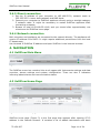
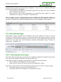
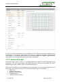
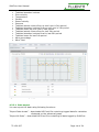
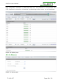
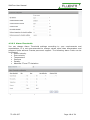
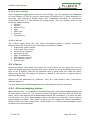
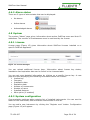
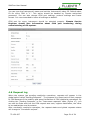
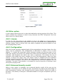
1
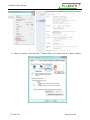
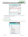
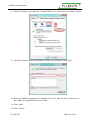
Document number: 72.120.607 Document title: Fluenta Flare Gas Meter FGM 160 SoftFlow User Manual Scope: ISO 9001:2008 §5.7 Additional Information (when applicable) H 04.11.2014 Updated for SF 2.0 JR JB AP MW MW G JB MW KH MW MW MS MKJ KH MW MW AN DD KH BSn MW AN DD KH BSn MW DD MW - JJB JJB B 25.03.2013 Updated with nitro option Browsers added, section regarding 30.11.2012 administrator account added Updated information regarding connection 05.03.2012 details Expanded information regarding 24.01.2012 installation prerequisites and connection details Paragraph 3.3 Interface between FGM160 21.10.2011 and SoftFlow updated concerning connecting the FISCAL computer 24.10.2011 Text updated DD YA - JJB JJB A 19.08.2011 First release MW KET - JJB JJB Review Review by QA Approved F E D C Rev. Issue date index Replacement for: Fluenta source doc. (for translations): Reason for issue Author Review Total pages: 24 SoftFlow User Manual TABLE OF CONTENTS 1. Purpose ...................................................................................................... 4 2. Abbreviations/definitions........................................................................... 4 2.1 Abbreviations: .......................................................................................... 4 3. General....................................................................................................... 4 3.1 General information .................................................................................. 4 3.2 Installation guide ...................................................................................... 5 3.2.1 Components list ............................................................................... 5 3.2.2 Hook-up instructions ........................................................................ 5 3.3 Interface between FGM160 and SoftFlow ..................................................... 6 3.4 Connecting to SoftFlow .............................................................................. 7 3.4.1 Google Chrome ................................................................................ 7 3.4.2 Internet explorer ............................................................................. 9 3.4.3 Direct connection ........................................................................... 11 3.4.4 Network connection ........................................................................ 11 4. Navigation ................................................................................................ 11 4.1 SoftFlow Main Menu ................................................................................ 11 4.2 SoftFlow Home Page ............................................................................... 11 4.3 Instruments page ................................................................................... 12 4.3.1 Instruments Overview .................................................................... 12 4.3.2 Advanced Graph ............................................................................ 13 4.3.3 Instruments Uptime ....................................................................... 15 4.3.4 Alarms .......................................................................................... 16 4.3.5 Configuration................................................................................. 17 4.4 Alarms ................................................................................................... 19 4.4.1 Acknowledging alarms .................................................................... 19 4.4.2 Alarm status .................................................................................. 20 4.5 System .................................................................................................. 20 4.5.1 License ......................................................................................... 20 4.5.2 System configuration ...................................................................... 20 4.6 Request log ............................................................................................ 21 4.7 Company administrator account................................................................ 22 4.7.1 System – user management ............................................................ 22 4.8 Nitro option ............................................................................................ 23 4.8.1 License ......................................................................................... 23 4.8.2 Configuration................................................................................. 23 4.8.3 Enhanced density model ................................................................. 23 5. Troubleshooting ....................................................................................... 24 72.120.607 Page 2 of 24 SoftFlow User Manual TABLE OF FIGURES Figure Figure Figure Figure Figure Figure Figure Figure Figure Figure Figure Figure Figure Figure Figure Figure Figure Figure 1. Example topology of SoftFlow network (doc. no. 77.120.516). ................... 7 2. SoftFlow Menu bar. ............................................................................. 11 3. SoftFlow Home page with one instrument added. ................................... 11 4. Active alarms table. ............................................................................ 12 5. Instruments Sub-menu bar. ................................................................. 12 6. Overview page. .................................................................................. 13 7. Advanced Graph page. ........................................................................ 14 8. Advanced Graph Scaling. ..................................................................... 15 9. Advanced Graph template select drop-down list. .................................... 15 10. Uptime page. ................................................................................... 16 11. Alarms page..................................................................................... 16 12. Instruments configuration main page. ................................................. 17 13. Instrument configuration. .................................................................. 18 14. Alarm thresholds configuration ........................................................... 18 15. License manager. ............................................................................. 20 16. Registering new Instrument. .............................................................. 21 17. Pending requests table. ..................................................................... 22 18. Edit user. ......................................................................................... 23 72.120.607 Page 3 of 24 SoftFlow User Manual 1. PURPOSE The purpose of this document is to give a detailed description of how the SoftFlow operates. This document will only cover the section related to the Operator interface. Configuration and service section applies to Fluenta service and support personnel only. Basic information about interface between FGM 160 and SoftFlow will be described. More detailed information on FGM configuration can be found in FGM 160 User Manual Portfolio. 2. ABBREVIATIONS/DEFINITIONS 2.1 Abbreviations: FGM SF Flare Gas Meter SoftFlow 3. GENERAL 3.1 General information The SoftFlow appliance is network enabled and should be deployed in the local network, available on most sites. This enables users (customers) to access SoftFlow from any computer inside the network, significantly increases data availability. SoftFlow is accessed by using a wide range of browsers, so no local software installations are required. Placing the appliance inside customer’s network might require additional permissions from the local IT department. IMPORTANT! In order for the appliance to function properly, the following prerequisites must be met: A. FGM’s registry must contain current DATE and TIME. B. All registers read by SoftFlow must have valid values – this is performed via the FGM Operator Console. 72.120.607 Page 4 of 24 SoftFlow User Manual 3.2 Installation guide 3.2.1 Components list The following components are included in the SoftFlow installation set: SoftFlow appliance 1x Power cord 1x Mounting brackets 1x Cat 5 network cable 1x (option) 3.2.2 Hook-up instructions For details, see paragraph 3.4 - Connecting to SoftFlow 72.120.607 Page 5 of 24 SoftFlow User Manual For details, see paragraph 3.3 - Interface between FGM160 and SoftFlow NOTE: Remember that the FGM computers have to be turned on so that the SoftFlow output is available. 3.3 Interface between FGM160 and SoftFlow FGM 160 can be interfaced with the SoftFlow appliance either by 2- or 4- wire RS 485 cable connected to available COM port. The communication protocol setup is fixed at: Baudrate: Data bits: Stop bits: Parity: Protocol: 72.120.607 38400 8 1 None Modbus RTU Page 6 of 24 SoftFlow User Manual Figure 1. Example topology of SoftFlow network (doc. no. 77.120.516). Optional connections are explained in detail in FGM 160 User Manual Portfolio. NOTE: As SoftFlow appliance is working as a master in the Modbus network then in case the FISCAL computer is also connected to the FGM 160 it should be plugged in to a DCS port with a separate cable. See FGM 160 DCS Modbus Interface Specification for reference (document no. 72.120.305). 3.4 Connecting to SoftFlow There are two possible ways of getting access to SoftFlow – Direct Connection and Network Connection, which are discussed in sections 3.4.1 and 3.4.2 respectively. IMPORTANT: Before obtaining access, SoftFlow’s IP address needs to be added to the browser’s trusted sites zone. SoftFlow supports numerous browsers, but using Google Chrome is recommended. See the how-to details below: 3.4.1 Google Chrome 1. Open Google Chrome and select: Wrench Icon -> “Options” -> “Under the Hood” -> “Change proxy settings” 72.120.607 Page 7 of 24 SoftFlow User Manual 2. Select “Security” and click the “Trusted Sites” icon, then click the “Sites” button 72.120.607 Page 8 of 24 SoftFlow User Manual 3. Uncheck “Require server verification (https:) for all sites in this zone” 4. Enter the SoftFlow appliance IP address (see 3.4.3 and 3.4.4 for reference) in the “Add this website to the zone:” field 5. Click the “Add” button 6. Click the “Close” button 3.4.2 Internet explorer 7. Open Internet Explorer and select: Cogwheel Icon (Tools) -> “Internet options” 72.120.607 Page 9 of 24 SoftFlow User Manual 8. Select “Security” and click the “Trusted Sites” icon, then click the “Sites” button 9. Uncheck “Require server verification (https:) for all sites in this zone” 10.Enter the SoftFlow appliance IP address (see 3.4.1 and 3.4.2 for reference) in the “Add this website to the zone:” field 11.Click “Add”. 12.Click “Close”. 72.120.607 Page 10 of 24 SoftFlow User Manual 3.4.3 Direct connection 1. Set the IP address of your computer to 192.168.55.20, network mask to 255.255.255.0. Leave both gateway and DNS blank. 2. Connect your computer to SoftFlow appliance directly using a straight category 5 network cable. It might be necessary to restart SoftFlow appliance after connecting computer. 3. Browse to http://192.168.55.10/sf/ and you should after approximately one minute see the SoftFlow home page. 3.4.4 Network connection Both computer and appliance are connected to the network directly. The appliance will receive IP address from DHCP. It might require additional permissions from the local IT department. Use received IP SoftFlow IP address and open SoftFlow in the internet browser. 4. NAVIGATION 4.1 SoftFlow Main Menu Figure 2. SoftFlow Menu bar. The SoftFlow menu bar contains links to all pages with Instruments settings and data overview, alarms settings and system configuration. There are also 2 indicators informing about alarms and communication status. 4.2 SoftFlow Home Page Figure 3. SoftFlow Home page with one instrument added. SoftFlow home page (Figure 3) is the first page that appears after opening SF IP address in the internet browser. It contains a list of added instruments with basic 72.120.607 Page 11 of 24 SoftFlow User Manual measurements, data and alarm status displayed. There is also a subtotal calculated for each measurement displayed. Units used for each FGM in instruments table are the same as units configured on local display of FGM 160 Units used for Sub Total calculations are predefined and specific for every installation according to customer’s requirements. When an alarm on any of instruments occurs, an additional table appears (Figure 4). It lists existing alarms. Additional details about alarms can be viewed by clicking on the name of Alarm type and acknowledge them by “Acknowledge” action button. Figure 4. Active alarms table. 4.3 Instruments page Instruments option selected from SoftFlow menu bar allows the user to get an overview of measurements, export the data and make some basic changes in meters configuration. Selecting Instruments from menu bar opens additional sub-menu bar (Figure 5). The user can switch between installed instruments using “Choose an Instrument” dropdown list. Figure 5. Instruments Sub-menu bar. 4.3.1 Instruments Overview Sub-menu Overview (Figure 6) provides live readings of data for selected instruments. User can switch between FGM160 using drop-down list. Overview provides all relevant basic data from the FGM as shown below. List of values is fixed and cannot be changed. Units used for each FGM are the same as configured on FGM. Mass Flow, Actual Volume Flow and Standard Volume flow is fixed in a quick graph: The graph uses x-timeline for the last 48 hours. The graph cannot be configured or changed in any way. 72.120.607 Page 12 of 24 SoftFlow User Manual Figure 6. Overview page. If dual or double transmitters are installed in line different between readings from temperature or pressure transmitters are shows in absolute deviation temperature and pressure. This section also shows the nitro percentage in the gas composition and total weight of the nitro that was measured by the meter. 4.3.2 Advanced Graph Advanced graph page (Figure 7) provides advanced options of data displaying and exporting. You can select graph type and instrument from a drop down list. Units displayed are units predefined for a specific installation. Maximum 4 variables can be displayed simultaneously. You can select variables from drop down lists below the graph. The following values can be displayed: Mass flow Actual volume flow Standard volume flow Totalized mass Totalized actual volume 72.120.607 Page 13 of 24 SoftFlow User Manual Totalized standard volume Flow velocity Temperature Density Sound velocity Pressure Totalized actual volume flow up until now in 24h period Totalized standard volume flow up until now in 24h period Totalized mass up until now in 24h period Totalized actual volume flow for last 24h period Totalized standard volume flow for last 24h period Totalized mass for last 24h period Nitro percentage Nitro Total Figure 7. Advanced Graph page. 4.3.2.1 Data export You can export the data using following functions: “Export Data shown” – downloads MS Excel file containing logged data for variables displayed on the advanced graph “Export All Data” – downloads MS Excel file containing all data logged by SoftFlow 72.120.607 Page 14 of 24 SoftFlow User Manual You can use MS Excel to sort the data in different ways to diagnose possible problems with FGM. A guide for sorting data using MS Excel can be found in Appendix 1. NOTE: To open the MS Excel file, the user has to have the MS Excel version 2000 or newer installed on a computer. 4.3.2.2 Graph settings Graph parameters can be changed by selecting “Scale” function (Figure 8). It gives access to following settings: X-axis timeline X-axis resolution. (Min. value 1 minute) Figure 8. Advanced Graph Scaling. NOTE: By default, SoftFlow allows you to store data for 60 days per FGM. 4.3.2.3 Graph template Graph settings can be saved by clicking the button template name in the text field. To load saved template use the drop-down list (Figure 9) and then putting a Figure 9. Advanced Graph template select drop-down list. 4.3.3 Instruments Uptime You can find information about both FGMs and SoftFlow appliance uptime in “Uptime” page (Figure 10). Uptimes can be displayed for any period selected by the user. Detailed information about up and downtime can be exported to MS Excel file by using “Export Data shown” function. 72.120.607 Page 15 of 24 SoftFlow User Manual Flow computer’s downtime is detected when it is not possible to communicate with FGM. Appliance’s downtime is detected by detecting system power on and shutdown. Figure 10. Uptime page. 4.3.4 Alarms Figure 11. Alarms page. 72.120.607 Page 16 of 24 SoftFlow User Manual Using Alarms page you can display all existing and acknowledged alarms. Alarms for all instruments at the same time or for a specific FGM can be selected using a drop-down list. With the alarm status drop list user can display all alarms or decide if only active or inactive alarms should be displayed. You can select only acknowledged alarms to be displayed using a checkbox. More details regarding alarms can be found in the section describing Alarm page from the main menu bar (4.4). 4.3.5 Configuration Instrument configuration page (Figure 12) gives the user basic configuration options for all the instruments installed. Figure 12. Instruments configuration main page. 4.3.5.1 Configuration SoftFlow Basic doesn’t give access to configuration of parameters that can affect measurement. Configuration (Figure 13) can be viewed for every installed instrument but can only be changed by Fluenta authorized personnel. 72.120.607 Page 17 of 24 SoftFlow User Manual Figure 13. Instrument configuration. 4.3.5.2 Alarm Thresholds You can change Alarm Threshold settings according to your requirements and expectations. It is not recommended to change values other than temperature and pressure limits without Fluenta personnel support. The following alarm limits can be configured: Sound velocity Flow velocity Temperature Pressure Density Absolute PT and TT deviation Figure 14. Alarm thresholds configuration 72.120.607 Page 18 of 24 SoftFlow User Manual 4.3.5.3 Unit settings Unit configuration page gives access to unit settings. You can change units displayed on Local Display of FGM 160 and on home page of SoftFlow (4.2). Units displayed on Overview and Advanced Graph pages are predefined according to customers’ requirements and it is not possible to change them. You can change units for the following measurements: Velocity Volume Volume Flow Mass Mass Flow Pressure Temperature 4.3.5.4 About The “About” page gives the user basic information about a specific instrument selected from the drop-down list. Information provided includes: Instrument serial number Instrument Tag number Name of the company Name of the site Date of installation DSP firmware version IO firmware version System type 4.4 Alarms Advanced alarms view apart from basic list of all alarms (4.3.4) gives the user an option to display alarms in specific time range. Alarms for all instruments at the same time or for a specific FGM can be selected using a drop down list. With the alarm status drop list you can display all alarms or decide if only active or inactive alarms should be displayed. Alarms are not generated by SoftFlow. They are read directly from instrument’s internal registers. You can select only acknowledged alarms to be displayed using a checkbox. 4.4.1 Acknowledging alarms When alarms occur, it is possible to acknowledge them using acknowledge button next to every alarm on the list. This method informs the system that the user has seen the alarm. When new alarms and acknowledged alarms are separated, it is easier to take correct action. You click “Acknowledge” next to the alarm (or from the “Home” tab) to Acknowledge the alarm. The reason of alarm can be entered for better traceability. Global system will also change from “Active Alarms” to “Alarms Acknowledged” when all alarms are acknowledged. 72.120.607 Page 19 of 24 SoftFlow User Manual 4.4.2 Alarm status There are 3 types of alarm status that can be displayed: No alarms Active alarms Acknowledged alarms 4.5 System The system “About” page gives information about active SoftFlow users and their IP addresses. The number of simultaneous users is restricted by the license. 4.5.1 License License page (Figure 15) gives information about SoftFlow licenses installed on a specific SoftFlow appliance. Figure 15. License manager. You can upload additional license keys. Information about license key status, installation and expiration date can be found in the Licenses table. You can get more detailed information by clicking on a specific license key. A new page will open displaying the following information about the license: License key Company Installation date Expiration date Number of instruments Number of users Installed features Nitro option (if enabled) 4.5.2 System configuration Communication settings table contains list of installed instruments. You can see the status of the instrument, edit and delete instruments on the list. You can add a new instrument by clicking the “Register new” button. Configuration page (Figure 16) will appear. 72.120.607 Page 20 of 24 SoftFlow User Manual You can type the Instrument’s name and set the Instrument’s slave ID. Default slave ID for every FGM is “1”. This action should be handled by Fluenta authorized personnel. You can also change COM port settings, protocol settings and frame format. It is recommended to leave all settings as default. COM port for every instrument should be selected properly. Fluenta Service Engineer should give information about COM port numbering during commissioning of the system. Figure 16. Registering new Instrument. 4.6 Request log When the system has pending read/write operations, requests will appear in the global option called “Pending Requests”. The purpose is to keep track of each request to FGM because of the stability and speed limitations of FGM read/write operations. By clicking the “Pending Requests” in the “Instrument requests” table (Figure 17), you can see the Date and time the FGM request was sent, register destination, the value to be read/written and the status. After successful read/write operation, the request status and global requests status will change to “Successful request”. 72.120.607 Page 21 of 24 SoftFlow User Manual Figure 17. Pending requests table. 4.7 Company administrator account SoftFlow appliance gives possibility to create an account on “Company administrator” level. This kind of account extends user options and gives access to managing the network configuration. 4.7.1 System – user management The user management option gives information about all accounts created on the SoftFlow appliance. You can edit and delete other accounts. As an advanced user, you can change: Full name Login name Email User role Company Password 72.120.607 Page 22 of 24 SoftFlow User Manual Figure 18. Edit user. 4.8 Nitro option A nitro options allows the user to stop the totalization during purging of the flare. This option enables the customer to save money because the FGM “recognizes” the time when there is no flaring done. 4.8.1 License In order for the nitro option to be enabled, it has to be added as a license feature. This is a very important step because this mode can be enabled when generating the Softflow license. Only a license with nitro option enabled can give the ability to use the purging/flaring mode. 4.8.2 Configuration After the license has been uploaded and all the preparations have been done, the nitro option can be configured. The configuration is described in section 4.3.5.1 of this manual. To enable the automatic switch between purging and flaring mode of the FGM, the velocity limit which will indicate the switch has to be defined. There are two velocities used because this switch can have a hysteresis. This makes the line of operation more stable and more resistant to short flow disturbances. When the flow velocity is above the upper limit, the flaring mode is enabled and the totalizers increase according to the flow. When the flow velocity is below the lower limit, the purging mode is enabled. The flow is still measured but the fiscal totalizers are not increased. The Nitro Total totalizer is increased to show the amount of Nitrogen used during the purging mode. 4.8.3 Enhanced density model When a nitro option is available, the enhanced density model of the gas can be enabled. This allows you to define the gas composition by stating the percentage of each hydrocarbon fraction, the nitrogen and the carbon dioxide. When this mode is turned on, the density of the gas is calculated based on the gas composition given by the user. 72.120.607 Page 23 of 24 SoftFlow User Manual 5. TROUBLESHOOTING Q: How to change the SoftFlow IP address? A: It can be done remotely by connecting the SoftFlow appliance to an internet network and contacting Fluenta service and support. It is important to deliver a correct SoftFlow addresses before system installation to spare the time and effort needed for changing IP address remotely. Q: User cannot log in to the SoftFlow appliance. A: Please check if you are connecting with a proper url address (https://[SF_IP_address]/sf/). Please remember that only two active sessions can be made. User should always logout before closing Web browser. Q: User cannot produce trend graphs from the Excel export sheet. A: Please make sure that you converted cells into the number format. Q: When logging into SF you see the message that license is expired. A: Please contact Fluenta to obtain a new license. If you experience any other issues not covered by this troubleshooting section please contact: [email protected]. 72.120.607 Page 24 of 24