1
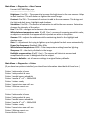
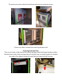
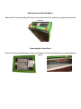
(847) 952-7533
Table of Contents
Cautions and Warnings …………………………………………………………………. 3
Service and Adjustable Menu ………………………………………………………… 4
Trouble Shooting …………………………………………………………………………… TBA
Quick Installation Guide ………………………………………………………………… 13
See our online Picture Guides for more information at http://www.FunStopPhotos.com
Cautions and Warnings:
Ensure that the installation and wiring comply with all applicable codes and other application
requirements
For indoor use only. Do not place in wet or exposed areas.
Refer all service to qualified service personnel.
Place the cabinet in its final position, taking care to ensure that ventilation openings are not
blocked and the cords and cables are not pinched.
Adjust the 4 cabinet leg levelers down such that the cabinet is level and does not move or
rock. Ensure that the cabinet wheels are raised up from the floor and are not supporting the
cabinet.
Service and Adjustable Menu
Press the service button located inside the coin door to enter into the service menu.
To navigate the menus, use the SELECT and ARROW buttons on the outside of the coin door.
Main Menu
Adjustments
Audits
Diagnostics
Software Update
System Information
Main Menu ->Adjustments
------- money adjustments ------Value of coin 1: $0.25
Value of coin 2: $0.25
Value of Second dollar bill acceptor: $1.00
Value of First dollar bill acceptor: $1.00
Price Per Play: $3.00 (Can be set to FREE PLAY)
Bonus strip price: none (Users can get another set of photos if they put in more $
Meter for dollar bill acceptor 1: 1
Meter for dollar bill acceptor 2: 2
Meter for coin acceptor: 1
-------sound adjustments ------Music: On/Off
Music Type: POP
Volume: 50% (up to 100)
------- attract mode options ------Rear camera attract sequence interval seconds: 60
Attract Mode Sounds: On/Off
Attract Mode Flash: On/Off – Flash the camera above the cabinet.
------- other adjustments ------Swap front and rear camera displays: off
Border select timeout in seconds: 65
Camera Tilt Adjustment Timeout in seconds: 45
Boarders – Allows the operator to turn on or off boarders individually.
Custom Photo strip Logo – select and choose to have the 4th photo panel display a logo **
Custom Advertisements – select and load advertisements for the rear monitor screen **
Change Time and Date
Set adjustments to defaults: Sets all adjustments to factory defaults
Factory Defaults: clears all lifetime audits.
If you are in need of custom art, backgrounds or advertisments, we can create and test the
art for you for an hourly fee. Please contact us for details.
Main Menu ->Audits
Lifetime Coin 1: $0.00
Lifetime Second Dollar Bill Acceptor: $0.00
Lifetime First Dollar Bill Acceptor: $0.00
Lifetime Plays: 0
------------------------Current Coin 1: $0.00
Current Second Dollar Bill Acceptor: $0.00
Current First Dollar Bill Acceptor: $0.00
Service credits: 0
Current Plays: 0
Current Credits: $0.00
------------------------Printer 1 Count since New Roll: 0
Printer 1 Lifetime Count: 0
Printer 2 Count since New Roll: 0
Printer 2 Lifetime Count: 0
------------------------Print current audits
Print and clear current audits
Print lifetime audits
Uptimes
Lifetime boarder audits
Current boarder audits
Clear Current Audits: Clears all the current audits for cash.
Clear Current Credits: clears out the current credits.
Main Menu ->Audits->Lifetime Border Audits
Tracks the lifetime use and selection of all the boarders.
Main Menu ->Audits->Current Border Audits
Tracks the use and selection of all boarders since last cleared.
Main Menu -> Diagnostics
Switches
Display
Audio test
Coin Meter
Lighting
Main Camera
Rear Camera
Printer
Restart Photo Booth
Main Menu -> Diagnostics -> Switches
This menu allows you to test each of the switches on the cabinet to make sure they are
working. When pressing a switch, the diagnostic screen will show the switch as ON.
Up: off
Down: off
Select: off
Test: off
Coin 1: off (not used)
Coin 2: off (not used)
Dollar bill acceptor: off
Volume up: off
(not used)
Volume down: off (not used)
Main Menu -> Diagnostics->Display
Allows you to choose several color diagnostic screens to display to help adjust the screen.
Main Menu -> Diagnostics -> Audio Test
Volume: 50 – the current volume of the audio test
Play/Stop Music – toggles the test music on or off.
Main Menu -> Diagnostics -> Coin Meter
These advance the physical coin meter for testing.
Advance Meter 1 one count
Advance Meter 1 five count
Advance Meter 1 ten count
Advance Meter 2 one count
Advance Meter 2 five count
Advance Meter 2 ten count
Main Menu -> Diagnostics -> Lighting
Allows the operator to test all the cabinet light functionality.
Printer error light: off
Photo Drop Lights: off
Cabinet Light: off
Select button lamp: off
UP button lamp: off
Down button lamp: off
Camera flash: off
---------------------------------------Toggle printer error light
Toggle photo drop light
Toggle cabinet light
Toggle select button lamp
Toggle up button lamp
Toggle down button lamp
Toggle camera flash
ALL LIGHT ON
ALL LIGHTS OFF
Main Menu -> Diagnostics -> Main Camera
Format: 960*720 15fps yuyv
--------------------------------------Brightness: 0 to 256 – The amount to increase the brightness to the rear camera. Helps
in dark locations. This will darken or lighten the overall image.
Contrast: 0 to 256 – The amount of contrast to add to the rear camera. This brings out
the light and dark tones, highlights and shadows.
Saturation: 0 to 256 – The amount of saturation to add to the rear camera. Saturation
changes the intensity of the colors.
Hue: 0 to 256 – changes and enhances color amounts. (on some cameras)
White balance temperature auto: 0 (off) 1 (on) – process of removing unrealistic color,
so objects or materials that appear white in person are white in the photo.
Gamma: 100 – adjusts the midtones while maintaining detail in the highlight and
shadow areas. (on some camers)
Gain: 0 – Adjustment for trying to lighten up or bring detail to dark areas automatically.
Power line frequency: Disabled, 50hz, 60hz
White balance temperature: 6500 – Color temperature setting based on lighting.
Sharpness: 32 – the clarity of details in the image.
Backlight compensation: 0 (off) 1 (on) – The camera will take into account and
compensate for a over lit background to the subject.
Camera Tilt Increment: amount the camera moves up and down for the user.
Revert to defaults – set all camera settings to original factory defaults.
Main Menu -> Diagnostics -> Rear Camera
Format: 640*480 30fps yuyv
--------------------------------------Brightness: 0 to 256 – The amount to increase the brightness to the rear camera. Helps
in dark locations. This will darken or lighten the overall image.
Contrast: 0 to 256 – The amount of contrast to add to the rear camera. This brings out
the light and dark tones, highlights and shadows.
Saturation: 0 to 256 – The amount of saturation to add to the rear camera. Saturation
changes the intensity of the colors.
Hue: 0 to 256 – changes and enhances color amounts.
White balance temperature auto: 0 (off) 1 (on) – process of removing unrealistic color,
so objects or materials that appear white in person are white in the photo.
Gamma: 100 – adjusts the midtones while maintaining detail in the highlight and
shadow areas.
Gain: 0 – Adjustment for trying to lighten up or bring detail to dark areas automatically.
Power line frequency: Disabled, 50hz, 60hz
White balance temperature: 6500 – Color temperature setting based on lighting.
Sharpness: 32 – the clarity of details in the image.
Backlight compensation: 0 (off) 1 (on) – The camera will take into account and
compensate for a over lit background to the subject.
Revert to defaults – set all camera settings to original factory defaults.
Main Menu -> Diagnostics -> Printer
(If you have two printers installed, you should see information about both of them here.)
Printer 1 usb vendor id: xxxx
Printer 1 usb product id: xxxx
Printer 1 model name: mitsubishi
Printer 1 media: 4” x 6” – 1844x1240
Printer 1 status: ready
Printer 1 count since new roll: xxx
Printer 1 lifetime count: xxx
--------------------------------Printer 2 usb vendor id: xxxx
Printer 2 usb product id: xxxx
Printer 2 model name: mitsubishi
Printer 2 media: 4” x 6” – 1844x1240
Printer 2 status: ready
Printer 2 count since new roll: xxx
Printer 2 lifetime count: xxx
Current Active Printer: x
Blink status led on printer 1 – turns the led on printer one on and off to help identify which
printer is currently printer 1.
Print test pattern on printer 1 – prints out a test pattern to printer 1
Blink status led on printer 2 – turns the led on printer one on and off to help identify which
printer is currently printer 2.
Print test pattern on printer 2 – prints out a test pattern to printer 1
Main Menu -> Diagnostics -> Restart Photo Booth
In some instances, either after a software update or install, it may be necessary to
restart the photo booth. Restarting it from the menu will cause just the software to update
which puts less strain on the printers and other powered devices.
Main Menu -> System Information
(Remember to check the TeamPlayInc.com website to make sure you are running the latest
version of the software for your machine!)
Application: tpi-photo-booth-x.x.x
Software Version: x.x.x
Build Date: time month, day, year
i/o board software version: 0.1.1
system release: linux 2.6.29.4 xxx
opengl version: 1.4 mesa 7.6-devel
Ethernet ip address:
Main Menu -> Software Update
If you have a new version of the software, you will need to go into this menu. Locate the
correct version of the software you want to load, and follow the instructions on the screen to
install the new software version.
Access Doors
There are a total of 3 access doors on the photo booth.
The rear door allows access to the main monitor, pc board, i/o board, main camera, and usb hub.
The coin door on the inside allows access to the dollar bill accepter and SERVICE button.
The printer entry door under the seat allows seat removal and printer access.
Printers can slide in and out after removing the lower bolt
Removing Inside the Glass.
There are 3 screws on the inside of the cabinet holding a brace that keeps the glass in place.
Remove these screws, then reaching around to the back, you can push the glass out towards
the inside of the cabinet through the small hole just above the light housing.
Removing the outside back glass.
Remove the 3 screws holding the brace on the top rear of the cabinet, lean glass forward and
slide up.
Removing the Curtain Rods
There are 3 bolts that hold each curtain rod in place. You can access them by removing the top
panel.
Quick Installation Guide
Ensure that the installation and wiring comply with all applicable codes and other application requirements.
For indoor use only. Do not place in wet or exposed areas.
Refer all service to qualified service personnel.
Installation
Move the cabinet to its intended location.
Install the female end of the A.C. mains line cord (provided in the parts box) with the IEC power connector
located on the rear of the cabinet. Install the male end a properly grounded power outlet.
Zip tie the power cord to the bridge lance to keep it from getting loose when the cabinet is moved.
Place the cabinet in its final position, taking care to ensure that ventilation openings are not blocked and the
cords and cables are not pinched.
Adjust the four cabinet leg levelers down such that the cabinet is level and does not move or rock. Ensure
that the cabinet wheels are raised up from the floor and are not supporting the cabinet.
Turn the cabinet power switch “ON.”
Top Camera Installation
Remove the access panel from the top of the photo booth via the two bolts.
Mount the access panel to the bottom side of the camera with the three bolts/nuts/washers provided.
Make sure to connect the wire connector inside the camera to the matching connector on top of the photo
booth, and replace the access panel on top of the photo booth.
Printer Paper Installation
Unlock, open, and remove the printer access door. Keys are zip-tied to the curtain rod outside the booth.
Press the “OPEN” button on the front of the printer door. The printer will unlock the door and allow the door to
be rotated down into the horizontal position.
o Ensure that the cabinet is connected to the A.C. power outlet.
o The cabinet must be “Turned On” in order to load paper into the printer.
Remove all shipping material from inside the printer.
Follow the paper and ribbon installation instructions displayed on the inside of the printer door.
o The paper support reels are located inside the parts box shipped with the cabinet.
o The ribbon support tray is located inside the parts box shipped with the cabinet.
Close the door by gently rotating the door up to the vertical position. The printer will then securely lock the
door into position.
o The printer will feed four sheets of paper out from the door when the paper and ribbon are correctly
loaded and the door is properly closed.
(See the included Manufacturer’s Printer Manual for more information and trouble-shooting.)
Configuration
Open the coin door and press the “TEST” button.
Use the up and down buttons to select the appropriate option.
Set pricing, location, and other options as required
Select “Exit” at the bottom of the menu to return to normal operation.
(See the full Fun Stop Photos Manual for Menu Navigation and Descriptions online at our webpage
www.TeamplayInc.com or www.FunStopPhotos.com )
Contact Information
TEAM PLAY, INC.
847.952.7533
847.952.7534
[email protected]
http://www.TeamPlayInc.com
Office Telephone
Office FAX
E-mail
Website