1
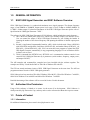
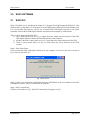
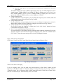
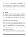
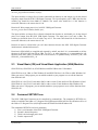
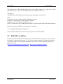
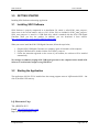
SG01 Software
User’s Manual
SG01 Software
USER’S MANUAL
LQ Electronics
Page 1 of 11
SG01 Software
User’s Manual
SG01 USER’S MANUAL
TABLE OF CONTENTS
Page #
1.0
GENERAL INFORMATION ......................................................................................................... 3
1.1
SG01 USB Signal Generator and SG01 Software Overview................................................. 3
1.2
Authorized Use Permission....................................................................................................... 3
1.3
Points of Contact ....................................................................................................................... 3
1.3.1
Information.............................................................................................................................. 3
2.0
SG01 SOFTWARE.......................................................................................................................... 4
2.1
SG01 GUI ................................................................................................................................... 4
2.2
SG01 API.................................................................................................................................... 8
2.3
Visual Basic (VB) and Visual Basic Application (VBA) Modules ...................................... 9
2.4
Command SETSG01.exe........................................................................................................... 9
2.5
SG01 API vs LabView............................................................................................................... 9
3.0
GETTING STARTED................................................................................................................... 11
3.1
Installing SG01 Software ........................................................................................................ 11
3.2
Starting the Application.......................................................................................................... 11
LQ Electronics
Page 2 of 11
SG01 Software
User’s Manual
1.0
GENERAL INFORMATION
1.1
SG01 USB Signal Generator and SG01 Software Overview
SG01 USB Signal Generator is a synthesized continuous wave signal generator. The Output frequency
range is from 40MHz to 3200MHz. Output power level range is from -23dBm to 10dBm (84dBuV to
117dBuV -50ohm output). For detailed parameters of the SG01 USB Signal Generator please refer to”
Specification for USB Signal Generator - SG01”.
The software for SG01 USB Signal Generator is SG01 Software, which includes three main elements:
1) One is the SG01 control panel (SG01.exe), which is user friendly Graphic User Interface (GUI).
User can control the output of SG01 USB Signal Generator by just clicking the buttons or
inputting the number of the desired frequency and inputting the number of desired output power
level.
2) Second is Application Programmable Interface (API), which includes static library (SG01lib.h
with SG01lib.lib) and dynamic -link library (SG01ALL.dll), and another library (SG01ALL_c.h,
SG01ALL_c.lib and SG01ALL_c.dll). Users can write their own programs to control the SG01
USB Signal Generator automatically in any programming languages. Even in Windows Office
software, such as Excel.
3) Third is command-line (SETSG01.exe). SETSG01.exe is a command at windows console. It can
control SG01 USB Signal Generator by 4 parameters (serial number, frequency, output power,
and output ON/OFF).
The API examples and command-line examples have been installed with the software together. The
examples are built by Visual Studio 2005 at 32bit OS of Windows XP with SP3.
The GUI can control maximum 4 units of SG01 USB Signal Generators at the same time. The API can
program maximum 30 units of SG01 USB signal generators.
SG01 Software has been tested on 32bit OS of Windows XP with SP3, 32bit OS of Windows 7 with SP1,
64bit OS of Windows Vista with SP1 and 64bit OS of Windows 7 with SP1.
Detailed functioning of the software will be covered in Section 2 in this document.
1.2
Authorized Use Permission
Usage of this software is limited to its owner via the terms of its development. SG01 Software is
wholly owned by LQ Electronics Corp, and may not be used or referenced without their express consent.
1.3
Points of Contact
1.3.1 Information
For additional information, please email: [email protected].
LQ Electronics
Page 3 of 11
SG01 Software
2.0
SG01 SOFTWARE
2.1
SG01 GUI
User’s Manual
SG01 GUI (SG01.exe) is installed in the folder of C:\Program Files\LQElectronics\SG01GUI for 32bit
Windows OS or in the folder of C:\Program Files x(86)\LQElectroncis\SG01GUI for 64bit Windows OS.
It is a user friendly GUI and very easy for user to control SG01 USB Signal Generator. It can control
maximum 4 units of SG01 USB Signal Generator connected to the computer by USB interface.
There are three stages for the SG01 GUI.
1) One is SG01 Main Frame (see Fig.1), which shows the model and serial number of the SG01
USB Signal Generator connected at the USB interface of the computer.
2) Second is the SG01 control panel (see Fig. 2), which shows the control functions of the SG01.
3) Third is Sweep control panel (see Fig. 4), which shows the sweep functions of the SG01
software.
Stage 1: SG01 Main Frame
If you connected a SG01 USB Signal Generator on your computer, you will see the Icon as shown in
Fig.1 when you run SG01.exe.
Fig. 1 Main Frame
In Fig.1, SG01 is the model of the USB Signal Generator. SG001E8481 is the serial number of the SG01
USB Signal Generator, which is connected to the computer.
Stage 2: SG01 Control Panel
Click the serial number in Fig.1, the SG01 Control Panel will appear as Fig.2
LQ Electronics
Page 4 of 11
SG01 Software
User’s Manual
Fig.2 SG01 Control Panel
Fig.3 illustrates the items which are shown in the Fig.2.
Fig.3 Items appeared on the SG01 Control Panel
The functions of each item is explained as below,
LQ Electronics
Page 5 of 11
SG01 Software
User’s Manual
1. Frequency window
Output frequency of the signal generator is shown in the window.
2. MHz horizontal bar
Move the bar to set the output frequency by MHz.
3. KHz horizontal bar
Move the bar to set output frequency by KHz.
4. Frequency Unit select
Select the frequency unit for the frequency number shown in the frequency window.
5. Serial number
Serial number of the SG01 USB Signal Generator connected to the computer
6. Model
The model of the USB Signal Generator
7. Device number
USB device number, which is assigned by the computer
8. Output Level Unit
Output power level unit selection: ticked for dBuV (50ohm output). Default is dBm.
9. Output on/off switch
Ticked (default) for output ON, un-ticked for output OFF
10. Output power horizontal bar
Move the bar to set output power level appeared in the output power level window
11. Output power level set button
Click the button to set the output power level of the SG01 USB Signal Generator
12. Output power level unit
Output power level unit for the number shown in the output power level window
13. Output power level window
Output power level number is shown in the window
14. Output frequency set button
Click the button to set output frequency for the SG01 USB Signal Generator
15. Output frequency unit
Output frequency unit for the number shown in the frequency window
16. Button for Sweep Icon
Click the button, Sweep Control Panel (Fig.4) will show
17. Button for frequency and power level to be stored into SG01 USB Signal Generator
Click the button, frequency and power level of current setting will be stored into USB Signal
Generator, so that the signal generator can be run without computer.
Using the SG01 Control Panel
• Set frequency
There are two ways to set the SG01 output frequency
A. Click the frequency window and key in desired frequency , then click “Set” button
B. Move the frequency horizontal bar (MHz and KHz) to input desired frequency, then click
“Set” button
The default frequency unit is KHz. Frequency input range should be from 40MHz to 3200Mz.
Frequency set to be less than 40MHz will be set to 40MHz. Frequency set to be greater than
3200MHz will be set to 3200MHz.
• Set output power Level
There are two ways to set the SG01 output power level
A. Click the output power level window and key in desired output power, then click “Set”
button
LQ Electronics
Page 6 of 11
SG01 Software
•
•
•
•
User’s Manual
B. Move the output power level horizontal bar to input desired output power, then click
“Set” button
The default output power level is 0dBm. Output power level step is 0.5dB. Output power level
should between -23dBm (84dBuV) and 10dBm (117dBuV). Output power level set to be less
than -23dBm (84dBuV) will be set to be -23dBm(or 84dBuV). Output power level set to be
greater than 10dBm (117dBuV) will be set to be 10dBm (or 117dBuV).
Change Frequency unit
For the convenience to input frequency you can change the frequency unit to be KHz, MHz and
GHz through Frequency unit select (refer to Fig.3 item 4).
Change output power unit
For the convenience to input output power level, you can change the output power unit to be
dBm or dBuV (which is based on 50ohm) by ticking the level unit (refer to Fig.3 item 8).
Sweep output power level or frequency range
If you need to sweep the frequency or output power level, click “Sweep” button, the Sweep
Control Panel will appear (see Fig.4).
Store Current setting for frequency and power level
If you need the SG01 USB Signal Generator working without computer connection, first set the
frequency and power level to be desired frequency and power level. Then click “STORE” button
(Fig.3 item 17), then the current setting will be saved to USB Signal Generator.
Stage 3: SG01 Sweep Control Panel
Click “Sweep” button” in SG01 Control Panel, Sweep Control Panel will show in Fig.4.
Fig.4 Sweep control panel
There are two lines for sweeping
.
1) One is frequency sweep. You can input sweep start frequency at “Start Point” window and end
frequency at “End Point” window at “Frequency Sweep” line, input frequency step at ”Step” window at
“Frequency Sweep” line. All frequency units are KHz. Input delay time at “Delay time” window. Delay
time unit is millisecond (ms). Maximum delay time is 60 seconds.
LQ Electronics
Page 7 of 11
SG01 Software
User’s Manual
After you input the desired start frequency, end frequency, frequency step and delay time, click
“Frequency Sweep” to start the sweep
2) Another is output power level sweep. You can input sweep start power level by click up-down button
at “Start Point” window and end power level by click up-down button at “End Point” window, input
power level step by click up-down button at “Step” window at “Output Level Sweep” line. Delay time
unit is millisecond (ms). Maximum delay time is 60 seconds. Power level sweep unit can be set to dBm
or dBuV by ticking “Level Unit” in Fig. 4.
After you input the desired start output power level, end point of output power level, output power level
step and delay time, click “Level Sweep” to start the sweep.
2.2
SG01 API
SG01 API is comprised of header file SG01lib.h, static library SG01lib.lib and dynamic-link library
SG01All.dll, and another library (SG01ALL_c.h, SG01ALL_c.lib and SG01ALL_c.dll). The files are
installed in the folder of C:\Program Files\LQElectronics\SG01API for 32bit Windows OS or C:\Program
Files (x86)\LQElectronics\SG01API for 64bit Windows OS. The static library and dynamic library are
written of Visual Studio 2005 C++ and can be called by user’s programs in any languages at Windows
OS, such as VB, VBA or C/C++. It is very convenient to call the functions in the libraries. Even in Office
Excel, you can still call the functions by VBA to drive the SG01 USB Signal Generator by calling the
functions in SG01ALL.dll. The maximum devices the libraries can drive are 30.
SG01 API functions
Function A: Get a specific SG01 Signal Generator USB device number
int GetDeviceNumber(char* sn);
The input variable of the function is a character pointer sn, where stores the serial number of the SG01
USB Signal Generator. The return value is the USB device number assigned by the computer the SG01
connected. If there is an error, the return value is 100. Windows OS assigns a unique number to a specific
USB device when a USB device is plugged into a computer. When the SG01 USB Signal Generator is
unplugged and re-plugged with other USB devices together, the assigned USB device number may
change or may not change depending whether other USB devices use the same USB protocol driver.
When a USB device is plugged into the computer, the first task is to get the device number assigned by
the computer.
The serial number can be obtained from the outside label of the SG01 USB Signal Generator or by
opening SG01 GUI, which will show the serial numbers of the SG01 plugged to the computer.
Function B: Output power ON/OFF
int output_ONOFF(int DeviceNumber, bool onoff);
The input variables are integer DeviceNumber obtained from function A, and Boolean onoff for the
output on/off (or 1/0). The function is to control the SG01 USB Signal Generator output on / off. The
return value should be 0 if function is successful. Otherwise, the return value is 100.
Function C: Write a Frequency to Signal Generator
LQ Electronics
Page 8 of 11
SG01 Software
User’s Manual
int write_freq(int DeviceNumber, int freq);
The input variables are integer DeviceNumber obtained from function A, and integer freq for the desired
frequency output from the SG01 USB Signal Generator. The input frequency unit is KHz, therefore the
variable freq should be from 40000 to 3200000. The return value should be 0 if the function is
successful. Otherwise, the return value is 100.
Function D: Write output power Level to SG01 USB Signal Generator
int write_pwr(int DeviceNumber,double pwr);
The input variables are integer DeviceNumber obtained from function A, and double pwr for the desired
power level output from the SG01 USB Signal Generator. The input power level unit is dBm. The
variable pwr should be from -23 to 10 with a step of 0.5. The return value should be 0 if the function is
successful. Otherwise, the return value is 100.
Function A must be called before you call other functions because the SG01 USB Signal Generator
initialization is included in function A.
Functions in SG01All.dll are compiled and exported by stdcall, not cdecl. It is recommended to call the
functions in SG01ALL.dll from VB or VBA. For C/C++ or other languages, it is recommended to call
functions from static library of SG01lib.lib with SG01lib.h, or dynamic library SG01ALL_c.dll, with
SG01ALL_c.lib and SG01ALL_c.h.
2.3
Visual Basic (VB) and Visual Basic Application (VBA) Modules
SG01VB32.bas, SG01VB32.vb, SG01VB64.bas and SG01VB64.vb are VB modules.
SG01VB32.bas is for VBA on 32bit Window OS and SG01VB64.bas is for VBA on 64bit Windows OS.
When you write a VBA program, you can add the module to your program so as to call the functions
from SG01ALL.dll.
SG01VB32.vb is for VB in Visual studio 2005 or other version Visual studio on 32bit Windows OS and
SG01VB64.vb is for VB in Visual studio 2005 or other version Visual Studio on 64bit Windows OS.
When you write a VB program, you can add the module to your program so as to call the functions from
SG01ALL.dll.
2.4
Command SETSG01.exe
The SG01 USB Signal Generator can be controlled by command-line. The command is SETSG01.exe,
which is installed in the folder of C:\Program Files\LQElectronics\SG01API for 32bit Windows OS or in
the folder of C:\Program Files x(86)\LQElectronics\SG01API for 64bit Windows OS.
The command of SETSG01.exe has 4 parameters,
1) First is serial number of the SG01 USB Signal Generator
2) Second is desired frequency
3) Third is desired output power level
4) Forth is output on off
LQ Electronics
Page 9 of 11
SG01 Software
User’s Manual
The frequency unit is KHz and the output power level is dBm. Output on is 1 and off is 0. Four
parameters must be set in one command to drive the SG01 USB Signal Generator.
The format is,
>SETSG01(space)Serialnumber(space)Frequency(space)Outputpower(space)Onoff
Where,
Serialnumber: the serial number of SG01 USB Signal Generator
Frequency: desired frequency in KHz (40000 to 3200000)
Outputpower: desired output power in dBm (-23 to 10)
Onoff: 1 (for turn on the SG01 USB Signal Generator) or 0 (for turn off the SG01 USB Signal Generator)
Example, if you copy SETSG01.exe to a directory C:\user, then:
C:\user>SETSG01 SG001E8481 1000000 10 1
will set the SG01 USB Signal Generator to output signal to be 1GHz and 10dBm.
2.5
SG01 API vs LabView
It is possible for SG01 API to be loaded into LabView because functions in SG01ALL_c.dll are exported
by standard C format, headed by extern “C”. LabView can import third party dll by importing .lib and .h,
or by function node in the dll. Detailed information on how to call a function from third party library,
please refer to link:
http://www.ni.com/white-paper/3341/en/#toc5 or http://www.ni.com/tutorial/3009/en/
LQ Electronics
Page 10 of 11
SG01 Software
3.0
User’s Manual
GETTING STARTED
Installing SG01 Software and starting Application
3.1
Installing SG01 Software
SG01 Software is properly compressed in an installation file, which is called SG01_vnnn_setup.exe,
where vnnn is the version number, such as v201. All the files are included in SG01_vnnn_setup.exe.
SG01_vnnn_setup.exe is stored in a USB flash drive which is attached with the SG01 USB Signal
Generator when you buy the product. In addition, you can download it from website:
http://www.lqelectronics.com/support/USBSG/download.html
When you start to install the SG01 USB Signal Generator, follow the steps below,
1. Plug the SG01 USB Signal Generator to a computer; ignore all reminders of the computer.
2. Plug the USB flash drive, double-click the file of SG01_setup.exe
3. Follow the instruction appeared on the screen of your monitor, the software will be installed
automatically.
We strongly recommend you plug SG01 USB signal generator to the computer before install SG01
Software to avoid window assigns wrong USB driver.
3.2
Starting the Application
The application of SG01 GUI is installed into the startup program menu at LQElectronics\SG01\. Just
click it, the SG01 GUI starts up.
LQ Electronics Corp
Tel: (408)836-8112
Email: [email protected]
http://www.lqelectronics.com
11LQ Electronics
Page 10 of 11