1
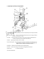
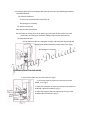
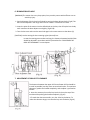
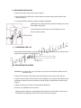
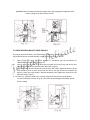
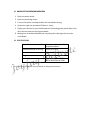
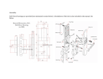
Drilling Apparatus
User’s Manual
1. SAFETY PRECAUTIONS
(1.) Don’t use this machine for other purposes than drilling the lens and cutting the lens
notch;
(2.) While the machine is working, don’t touch the turning wheels to avoid getting
injured;
(3.) Don’t use this machine when the power requirements (voltage and frequency) are
not met, you should be clear about the actual working power supply;
(4.) Don’t put the machine at the place of high temperature and sun shining;
(5.) If any liquid or other materials come into the machine, turn the switch off
immediately and pull the plug out of the wall socket; Please don’t start the machine
again until the machine is thoroughly checked and repaired by an expert in this line;
(6.) Don’t install other parts at will except the original parts of this machine;
(7.) Don’t have the machine too heavy working load, don’t dash any parts of this
machine.
2. NAMES AND FUNCTIONS OF COMPONENTS
1. Drill Bits Two drill bits of the same style, drill a lens simultaneously from the upper and lower
sides.
2.3. Reamer Bore Adjuster Reams the drilled hole with high accuracy in the range of 0.8mm
to 2.8mm in increments of 0.2mm.
4.7. Switch
5. Handle
To keep the drill bits and reamer running, push the switch knob backward. To
run them momentarily, pull the switch knob toward you.
By pushing this handle, the lens is drilled.
6. Lens Positioning Dial Sets the lens position relatively to the drill bits. The distance from an
edge of the lens to the point to be drilled can be adjusted in the
range of 2.0 mm to 8.0mm in increments of 0.5mm.
8. Hand Rest Stabilizes the hand holding a lens for drilling properly.
9. Oil Bath
Contains the cutting oil to be used for drilling glass(mineral) lenses.
10. Motor Cap
13.14. Notch Adjust Knob
11.12.Notch Saw Wheel.
3. MARKING DRILLING POINTS ON LENS
1. First wrap up both surface of the lens with an adhesive tape to protect it from any
accidental scratch.
2. Put in place the dummy lens removed from the frame over the lens to be drilled. and
firmly fix both lenses each other with an adhesive tape. (Fig.2)
3. Mark points onto the lens through the holes on the dummy lens with a marking pen.
(Fig.2)
4. Remove the dummy lens from the lens and check to make sure the points marked on the
lens are placed correctly by applying each part of the frame to the lens as shown in Fig.3.
4. DRILLING LENS
1. Put an edge of the lens to the lens check pad and adjust the lens position by turning the
lens positioning dial so that the points of the drill bits exactly come onto the drilling point
marked on the lens. (Fig.4)
2. Hold the lens by hand and keep the lens surface to be drilled, horizontally. Adjust the
height of the hand rest properly by turning a knob located under the hand rest, so that
your hand holding the lens can be stabilized. (Fig.5)
3. Switch the power on and on trial, make a slight hole onto the point marked on the lens,
by pushing the handle carefully. (Fig.5) Then check to make sure the trial hole is made in
place.
4. Practically drill the lens. According to the material of the lens, the following procedures
should be followed:
For Plastic (CR-39) Lens
The lens can be placed either side of face up.
No cutting oil is necessary.
For Glass (mineral) Lens
Place the lens back-face side up.
Put the accessory cutting oil in the oil bath (Fig.1), and soak the part of the lens to be
processed in the cutting oil whenever drilling scraps become white and dry.
For Polycarbonate Lens
Do not attempt to drill at a sitting but carefully and slowly drill by pushing and
releasing the handle alternately several times over. (Fig.6)
No cutting oil is necessary.
5. DRILLING WITH SUCTION LENS HOLDER
1. Set the lens holder arm onto the hand rest. (Fig.7)
2. Fix the lens with the suction cup and set it onto the
holder arm. (Fig.7)
3. Adjust the inclination of the lens so that the lens surface to
be drilled is placed horizontally. (Fig.7)
4. Adjust the height of the lens properly by turning a knob
located under the hand rest. (Fig.7)
6. REAMING DRILLED HOLE
[WARNING] The reamer has a very sharp point; Carry out this process with sufficient care to
avoid any injury.
1. Set the diameter of the hole to be finished by turning the bore adjuster knob. (Fig.8) The
bore can be adjusted in the range of 0.8 mm to 2.8mm in increments of 0.2mm.
2. Insert the point of the reamer into the drilled hole on the lens, then lift up the lens slowly
until it touches the bore adjuster arm slightly. (Fig.9 & 8)
3. Turn the lens over and ream the same hole again in the same manner as the above (2).
[CAUTION] Use the cutting oil when reaming a glass (mineral) lens.
In case the reaming process takes too long, the clearance between both drill bits
should be adjusted in accordance with the procedures for “ADJUSTMENT OF
DRILL BITS’CLEARANCE” in next chapter.
7. ADJUSTMENT OF DRILL BITS’ CLEARANCE
The clearance between the upper drill bit and lower drill bit should be
as small as possible, but they must not touch each other. The optimum
clearances, pushes the handle completely, and to adjust it, proceed as
follows:
1. Insert the accessory 3mm allen key into the hole on the top of the
machine while pushing the handle completely. (Fig.10)
2.To make the clearance smaller, turn the allen key clockwise. To
make the clearance larger, turn the allen key anti-clockwise. (Fig.10)
8. REPLACEMENT OF DRILL BIT
1. Remove the motor cap from the motor. (Fig.11)
2. Grip the neck of the drill bit with a plier and turn the motor knob, and the drill bit will
come off. (Fig.11)
3. To reset the drill bit, follow the above procedures oppositely.
[NOTE] Both the upper and lower drill bits should be set so that
those edges align strictly.
As both drill bits are the same in size and shape, they can
be set to either position.
9. SHARPENING DRILL BIT
If the drill bit becomes dull in the long period of use, it can be sharpened on a whetstone by
using the accessory drill bit holder. (Fig.12)
10. REPLACEMENT OF REAMER
[WARNING] The reamer has a very sharp point. Carry out this work with sufficient care to
avoid any injury.
1. Remove the reamer by loosening its setscrew located on the reamer chuck. (Fig.13)
2. Insert the new reamer into the reamer chuck completely. Then tighten the setscrew while
gripping the lower drill chuck and reamer chuck by fingers so that both chucks don’t play.
(Fig.13)
3. Check to make sure the reamer rotates without deflection.
4. If there is any deflection on the reamer…..
Depress the bore adjuster arm completely and release it from the reamer. Then correct
the deflection by gripping the haft of the reamer with a plier. (Fig.14)
[WARNING] Do not attempt to bend the reamer with a plier gripping the edge part of the
reamer. Doing so can break off the reamer.
11. ONE-SIDED DRILLING WITH TWIST DRILL BIT
By using an optional accessory “one-sided drilling attachment”, plastic (CR-39) and
polycarbonate lenses can be drilled with a twist drill bit of 0.8mm to 2.2mm.
1.
Take off both the upper and lower drill bits in accordance with the procedures for
“REPLACEMENT OF DRILL BIT” on Page 3-1.
2.
Insert a twist drill bit (Item # TD-160) into the upper drill chuck firmly and set the lens
receptacle (Item # TD-161) over the lower drill chuck. (Fig-15)
3.
Insert a twist drill bit (Item # TD-162-) into the twist drill holder. Adjust the position of the
twist drill bit so that its point comes into the hole on the top of the lens receptacle by
approx. 1.0mm when the handle is pushed completely, then tighten the setscrew on the
twist drill holder. (Fig.15)
4. To drill a lens, adjust the hand rest in a proper position so that the lens can be placed
correctly and stably as shown in Fig.16. Then push the handle lightly and slowly. Do not
drill at a sitting.
12. GROOVE CUTTING OPERATION INSTRUCTION
1. Open the power switch;
2. Open the protecting covers;
3. Turn on the switch, checking whether the saw wheels turning;
4. Choose the right size saw wheel (0.8mm or 1mm);
5. Tightly press the lens in your both thumbs on the working plate; please keep s low
when the lens meet the turning saw wheel;
6. Moving lens at the desirable distance comparing the scale to get the accurate
notch depth.
13. SPECIFICATIONS
Materials of Lens Acceptable
Possible Diameter of Drilling
Glass(mineral)plastic(cr-39)
Polycarbonate/etc.
0.8mm-to-2.8mm
Dimensions
260(W)x220(D)x275(H)mm
Weight
3 kg
Power Requirements
100 to 120V/60Hz AC 25W or
200 to 240V/50Hz AC 15W
The specifications and appearance are subject to change without notice.