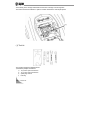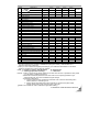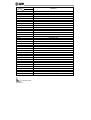
1
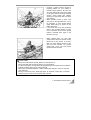
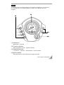
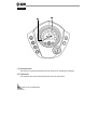
THE ARTICLES MENTIONED BELOW ARE APPLICABLE ONLY FOR
THE UNITED STATES AND CANADA.
1. NOISE EMISSION WARRANTY
SANYANG INDUSTRY CO.,LTD. warrants that this exhaust system, at the time of sale,
meets all applicable U.S. EPA Federal noise standards. This warranty extends to the first
person who buys this exhaust system for purposes other than resale, and to all subsequent
buyers. Warranty claims should be directed to:
3,chung-Hua Road, Hukou, Hsin-Chu Taiwan, R.O.C
Tel:+886 35981911
Fax:+886 35981844
2. TAMPERING WARNING
Tampering with noise control system prohibited. Federal law prohibits the following acts or
causing thereof:
(1) The removal or rendering inoperative by any person other than for purposes of
maintenance, repair, or replacement, of any device or element of design incorporated
into any new vehicle for the purpose of noise control prior to its sale or delivery to the
ultimate purchaser or while it is in use, or
(2) The use of the vehicle after such device or element of design has been removed or
rendered inoperative by any person.
Among those acts presumed to constitute tampering are the acts listed below.
(1) Removal of, or puncturing the muffler, baffles, header pipes or any other component
which conducts exhaust gases.
(2) Removal or puncturing of any part of the intake system.
(3) Lack of proper maintenance.
Replacing any moving part of the vehicle, or parts of the exhaust or intake system, with parts
other than those specified by the manufacturer .t 80
3. SAFETY INFORMATION
Always wear your helmet (dot approved) correctly fastened. Do not carry loose items and
always wear suitable protective clothes, and protective eyewear.
Good psychophysical conditions are very important for safe operation.
Do not operate under the influence of drugs and/or alcohol.
Do not operate in state of physical fatigue or drowsiness.
Slow down on slippery surfaces , unfamiliar terrain and when visibility is reduced.
Be alert when operating this vehicle.
Do not exceed weight capacity.
The safety, stability and handling of this motorcycle may be adversely affected by the
addition of accessories or luggage.
Do not install accessory or replacement parts not approved by sym.
Failure to follow these warnings could lead to an accident, serious injuries or death.
Use unleaded fuel octane rating (R+M)/2 method of between 87&92.
Read owners manual carefully before operating this scooter.
Obey posted speed limit and other traffic signs and signals.
4. SAFETY DEFECT REPORT
SANYANG INDUSTRY CO., Ltd.
NO. 3,chung-Hua Road
Hukou Shiang
Hsin-Chu County, 303
Taiwan, R.O.C
Reporting Safety Defects
If you believe that your vehicle has a defect which could cause a crash or could cause injury or
death, you should immediately inform the National Highway Traffic Safety Administration
(NHTSA) in addition to notifying Sanyang Industry Co., Ltd.
If NHTSA receives similar complaints, it may open an investigation, and if it finds that a safety
defect exists in a group of vehicles, it may order a recall and remedy campaign.
However, NHTSA cannot become involved in and individual problems between you, your
dealer, or Sanyang Industry Co., Ltd.
To contact NHTSA you may either call the Auto Safety Hotline toll-free at
1-800-424-9393(366-0123 in Washington, DC area) or write to:
NHTSA
U.S.DEPARTMENT OF TRANSPORTATION
400 7 th Street SW,(NSA-11)
Washington, DC 205090.
You can also obtain other information about motor vehicle safety from the Hotline.
1.
2.
3.
4.
5.
CONTENTS ...................................................................................................... 1
USE GENUINE SPARE PARTS......................................................................... 3
CONTROL LOCATION ..................................................................................... 4
SAFE RIDING PRECAUTIONS........................................................................ 14
USE OF EACH COMPONENT ....................................................................... 19
Gauges .................................................................................................................................... 19
Instrument ............................................................................................................................... 20
Function indicator .................................................................................................................. 21
Gearshift indicator .................................................................................................................. 22
Ignition switch ......................................................................................................................... 23
Steering handle lock .............................................................................................................. 24
Use of buttons ........................................................................................................................ 25
Throttle lever ........................................................................................................................... 27
Gearshift lever 1 ..................................................................................................................... 28
Gearshift lever 2 ..................................................................................................................... 29
Seat removal .......................................................................................................................... 30
Fuel tank cap .......................................................................................................................... 31
Fuel Valve ............................................................................................................................... 32
Brake ....................................................................................................................................... 33
Parking brake ......................................................................................................................... 34
Rear cushion adjustment ...................................................................................................... 35
Accessory socket ................................................................................................................... 36
6. IMPORTANT POINTS AND CAUTIONS FOR STARTING ENGINE .............. 37
Starting & stopping the engine ............................................................................................. 37
Using the Recoil Starter ........................................................................................................ 38
Parking .................................................................................................................................... 38
1. CONTENTS
1
7. INSPECTION AND MAINTENANCE BEFORE RIDING ................................ 39
Brake 1 .................................................................................................................................... 39
Brake 2 .................................................................................................................................... 40
Engine oil inspection and change ........................................................................................ 41
Transmission oil inspection and change ............................................................................ 42
Oil filter cleaning .................................................................................................................... 43
Inspection of fuel level .......................................................................................................... 43
Coolant .................................................................................................................................... 44
Replenishment of coolant ..................................................................................................... 45
Spark plug replacement & inspection ................................................................................. 48
Battery ..................................................................................................................................... 49
Air cleaner ............................................................................................................................... 51
Fuse ......................................................................................................................................... 52
Tire ........................................................................................................................................... 53
8. TOOL KIT ........................................................................................................ 54
9. PERIODICAL MAINTENANCE SCHEDULE .................................................. 55
10. SPECIFICATION ............................................................................................ 56
11. POSTSCRIPT ................................................................................................. 57
2
1. CONTENTS
In order to maintain the ATV best performance, each part’s quality, material, and machined
precision must conform with the design requirements. “SYM Genuine Spare Parts” were
made from the same high quality materials used for the original ATV. No parts would be
sold to the market until they could meet the designed specifications through sophisticated
engineering and stringent quality control. Therefore, it is necessary to purchase “SYM
Genuine Spare Parts” from “SYM Authorized Dealers or Franchised Dealers” when
replacing spare parts. If you buy cheap, or fake substitute parts from the market, no
guarantee can be provided either for the quality or durability. Also, it may result in
unexpected troubles and lower the motorcycle’s performance.
Always use SYM Genuine Spare Parts to keep your ATV pure blood and to ensure its long
service life.
2. USE GENUINE SPARE PARTS
3
WARING MARK
WARNING
WARNING
WARNING
Improper tire pressure or
Overloading can cause loss of control.
Loss of control can result in
severe injury or death.
COLD TIRE PRESSURE
FRONT :27~35 kpa. 0.27~0.35 kgf/㎠
3.8~5.0 psi
REAR
Overloading this ATV or carrying cargo
Improper tire pressure or
Improperly can change handling,
Overloading can cause loss of
stability and braking performance
control.
and can lead to an accident.
Loss of control can result in
Never exceed the maximum rear cargo
severe injury or death.
limit (combined weight on the rear rack
COLD TIRE PRESSURE
and in the storage area) of: 30kg(66lbs).
FRONT :27±1 kpa.
0.27±0.1
Refer to instructions in the Owner’s
kgf/㎠
Manual.
3.8±0.2 psi
: 27~35 kpa. 0.27~0.35 kgf/㎠
3.8~5.0 psi
NOTICE
For your safety,a protection devise is
equipped to shut down the engine if
you shift to forwart or reverse at the
revolution higher 3200 rpm.
4
3. CONTROL LOCATION
WARNING
Operating this ATV if you are under
the age of 16 increases you
chance of severe injury or death.
NEVER operate this ATV if you
are under age 16.
WARNING
Towing an improperly loaded
Trailer can cause loss of control.
○Read owner’s manual.
○Tow weight limit:227kg(500lbs).
3. CONTROL LOCATION
5
Tool kit compartment
Owner`s manual storage
Rear cargo rack
Seat lock lever
Right footpeg
6
3. CONTROL LOCATION
Front brake fluid lever
Rear brake fluid lever
Headlight
Front brake lever
Power supply
Rear brake lever
Turn signal light
Left footpeg
3. CONTROL LOCATION
7
Fuel fill cap
Air cleaner
Setting at basket
Recoil Starter grip
Muffler
8
3. CONTROL LOCATION
Gearshift lever
Coolant reserve
tank
Rear brake pedal
Oil filler cap
3. CONTROL LOCATION
9
Rear brake fluid reservoir
Front brake fluid reservoir
Throttle
Choke Lever
Fuel fill cap
10
3. CONTROL LOCATION
Operating this ATV if you are under the
age of 16 increases you chance of
severe injury or death.
Do not operate after consuming alcohol
or drugs.
Operator’s performance capability is
reduced by the influence of alcohol or
drugs.
3. CONTROL LOCATION
11
Know the terrain where you ride. Ride
cautiously in unfamiliar areas. Stay alert
for holes, rocks, or roots in the terrain,
and other hidden hazards which may
cause the machine to upset.
Be familiar the terrain where you ride.
You may not have enough time to react
on the unfamiliar terrain such as hidden
rocks, bumps, or holes. Be sure to go
slowly any carefully when operating on
unfamiliar terrain.
12
3. CONTROL LOCATION
If your ATV has stalled or stopped and
you believe you can continue up the hill,
restart carefully to make sure you do
not lift the front wheels which could
cause you to lose control. If you are
unable to continue up the hill, dismount
the ATV on the uphill side. Physically
turn the ATV around and then descend
the hill.
Avoid wheelies and jumping. You may
lose control of the machine or overturn.
3. CONTROL LOCATION
13
To make a turn on level ground:
Steer the handlebar and lean your body
toward the inside of the turn. Leaning
helps balance the vehicle, and it feels
more comfortable. Leaning into a turn is
an important technique to master in
riding an ATV.
When approaching a curve, slow down
and begin to turn the handlebar. Next,
put your weight on the footboard to the
outside of the turn(opposite the turning
direction) and lean your upper body
forward into the turn. Use the throttle to
maintain an even speed during the turn.
To make a sharp turn at low speed:
It helps to shift your body slightly
forward on the seat, and lean inside, as
you steer the handlebar. Shifting weight
forward allows the rear wheels to turn
easier, and it also improves front-wheel
steering.
14 4. SAFE RIDING PRECAUTIONS
Travel when easy slippery road surface,
moves the body to front, is helpful to the
vehicles advance.
Although the from and rear brakes have
separate
controls,
your
ATV’s
four-wheel drive interconnects all four
wheels. So operating any brake con will
cause braking at both the front and rear
wheels.
As a general rule, the front braking
system provides about 70 percent of
total stopping power.
For full braking effectiveness, use both
the pedal and lever simultaneously.
Using braking systems will stop your
ATV faster with greater stability.
Test your brakes after leaving the water.
Do not continue to ride your ATV
without verifying that you have regained
proper braking ability.
4. SAFE RIDING PRECAUTIONS
15
Crossing Hills or Slopes
To maintain balance and stability when
riding across a slope, you need to shift
weight toward the uphill side of the
vehicle. To do this, move your body off
the center of the seat and lean toward
the uphill side.
Avoid hills with extremely slippery or
loose surfaces. Shift your weight to the
uphill side of the ATV.
Avoid crossing hills that are excessively
steep, slippery or rough.
Making Turns on Slopes
Compared to riding on level ground,
you may need to shift more weight ant
lean more when making turns on
slopes.
When ATV travel when rugged not
good path, the body slightly stands, is
helpful to the travel when the bodily
stability.
The ATV may slide during riding on
loose or slippery surfaces. To reduce
the tendency for the front wheels to
slide in loose or slippery conditions,
positioning your weight over the front
wheels will help.
If the rear wheels of ATV start to slide
sideways, steer in the direction of the
slide carefully. Applying the brakes or
accelerating is not recommended until
you have corrected the slide.
16
4. SAFE RIDING PRECAUTIONS
Crossing a sloping surface requires a
properly position on your weight to
maintain proper balance. Be sure that
you have learned the basic riding skills
on flat ground before crossing a sloping
surface. Avoid slopes with slippery
surfaces or rough terrain that may upset
your balance.
When traveling across a slope, lean
your body in the uphill direction. It may
be necessary to front wheels slightly
uphill. When riding on slopes, do not
make sharp turns.
If ATV does start to tip over, gradually
steer in the downhill direction if there
are no obstacles. Once recover proper
balance, gradually steer again in the
direction you to go.
When climbing hills, you must shift
weight toward the front wheels to help
keep them on the ground. To do this,
shift your body slightly forward on the
seat and lean forward. For greater
weight shift, move your body father
forward and lean forward.
CAUTION:
Always check the terrain carefully before you startup any hill.
Never climb hills with excessively slippery or loose surfaces.
To climb a hill, take a running start in an appropriate gear and speed for the conditions.
Maintain a steady speed as you ascend the hill.
Never open the throttle suddenly or make sudden gear changes. The ATV could flip
over backward.
Never go over the top of any hill at high speed. An obstacle, a sharp drop, or another
vehicle or person could be on the other side of the hill.
4. SAFE RIDING PRECAUTIONS
17
It’s usually advisable to descend hills
with the ATV pointed straight downhill.
Avoid angles that would cause the
vehicle to lean sharply to one side.
On downhills, shift your weight back.
As you approach a downhill, stop and
survey the terrain below. Never ride
past the limit of your visibility. Never
go down a hill at high speed.
Use mainly the rear brake to control
speed. Avoid using either the front
brake or rear brake hard or abruptly
when riding down hills.
Remember, braking effectiveness is
reduced on any hill with a loose
surface.
18
4. SAFE RIDING PRECAUTIONS
Gauges
The following is SYM ATV basic operation. The indicators and displays on your ATV keep
you informed, alert you to possible problems, and make your riding safer and more
enjoyable.
⑶
⑴
⑵
⑷
(1) Instrument:
Speedometer、Odometer
(2) Function indicator:
Water temperature indicator、High beam indicator
(3) Gearshift indicator:
Low indicator、Hi indicator、Neutral indicator、Reverse indicator
(4) Ignition switch:
The ignition switch is used for starting and stopping the engine.
5.USE OF EACH COMPONENT
19
Instrument
⑴
⑵
(1) Speedometer:
This shows your speed in kilometers per hour (km/h) and in mileage per hour(mph).
(2) Odometer:
This odometer shows the total kilometers this motor has been driven.
20
5.USE OF EACH COMPONENT
Function indicator
⑵
⑶
⑴
(1) Turn signal Indicator:
The left or right Indicator will be flashing according to the operated directions of turn
signal light switch when it is turned on.
(2) High beam indicator:
This indicator comes on when the high beam headlight switch is turned on.
(3) Water temperature indicator:
Lights when coolant temperature is high enough to adversely affect the service life of
the engine.
If the coolant high temperature indicator comes on while you are riding, immediately
bring the vehicle to a stop, turn the engine off and let it cool.
5.USE OF EACH COMPONENT
21
Gearshift indicator
⑴
⑵
⑶
⑷
(1) Low indicator:
Use this position to get more power when climbing, dragging extra load,
and for better acceleration.
(2) Hi indicator:
Use this position to ride forward.
Use this position for normal riding.
(3) Neutral indicator:
Lights when the transmission is in neutral.
Use neutral when you star the engine, or if it is necessary to stop briefly with the
engine idling.
(4) Reverse indicator:
Lights when the transmission is in reverse.
Use this position to ride reverse.
22
5.USE OF EACH COMPONENT
Ignition switch
⑵
(1) “
⑴
” position:
Engine can be started in this position.
Ignition switch key can not be removed.
(2) “OFF” position:
Engine is shut off and can not be started in this position.
Ignition switch key can be removed.
5.USE OF EACH COMPONENT
23
Steering handle lock
(1)
(1) Steering handle lock
The steering handle lock is located on the steering stem
directly below the steering head.
Turn the steering handle fully to the left.
Insert the ignition switch key into the lock.
Turn the key clockwise, then the steering handle can be locked.
Remove the Ignition switch key.
When unlocking, simply turn the key anti-clockwise.
NOTE:
For preventing the vehicle to be stolen, lock the handle bar when parked.
After locked, turn of the handle bar left and right to make sure it.
When leaving the vehicle, remember to remove the key.
24
5.USE OF EACH COMPONENT
Use of buttons
Left handle - switch 1
⑴
⑵
⑶
(1) Electrical Starter Button
This is a starting motor button (switch) for engine starting.
With the main switch "ON", press this button while holding the front or rear
brake lever will start the engine.
(2) High/Low Beam Switch
This is for high beam.
This is for low beam. (Please turn to low beam when riding in city)
When the switch is turned to this position, all lights will go off.
(3) Hazard Switch
The main switch in the〝 ON 〞 position, cuts according to this switch, four
directions lantern festivals dodge extinguish do move, also can simultaneously
dodge on the display board direction indicating lamp extinguishes does moves.
If stops the vehicle has when the transportation frequent dangerous position or
the vehicle the breakdown, may use the dangerous police to show the switch.
The cut to this position, on four directions lamps and the display board direction
indicating lamp namely extinguishes.
5.USE OF EACH COMPONENT
25
Use of buttons
Left handle - switch 2
⑴
⑵
⑶
(A)
(B)
(1) Turn Signal Light Switch
Right-side turn signal light flashing means you intend to make a right turn.
Left-side turn signal light flashing means you intend to make a left turn.
(2) Horn Switch
Press this button down when ignition switch is in the “ON” position to sound, the horn.
(3) Choke lever
〝(A)〞fully OFF ,〝(B)〞fully ON.
When the engine starts possibly can use reaches this point choke lever.
If the engine is will be cold, Choke lever transfers completely dials to ON (A) the
position.
In the festival throttle value closed situation, presses the start button.
26
5.USE OF EACH COMPONENT
Throttle lever
(A)
⑴
(B)
(1) Throttle lever control
(A) Acceleration :
Pulls the pole with the thumb pressure to be possible to advance engine rpm.
(B)Deceleration :
The release pulls on the pole the pressure, then reduces the engine rpm.
5.USE OF EACH COMPONENT
27
Gearshift lever 1
The gearshift lever has three position: LOW (L)、HI (H)、Neutral (N)、Reverse (R).
Low (L)
Use this position to get more power when climbing, dragging extra load, and for better
acceleration.
Hi (H)
Use this position for normal riding.
Neutral (N)
Use neutral when you start the engine, or if it is necessary to stop briefly with the engine
idling.
Reverse (R)
Use this position to ride in reverse.
If you need to ride in reverse, make sure the area behind you is clear and only operate the
ATV at low speed.
CAUTION:
Improperly operating reverse could cause you to hit an obstacle or person behind you,
resulting in serious injury.
Make sure there are no obstacles or people behind you before selecting reverse gear.
When it is safe to proceed, go slowly.
28
5.USE OF EACH COMPONENT
Gearshift lever 2
1.Bring the vehicle to a complete stop, then make sure the transmission is in neutral.
2.Depress and hold down the rear brake level.
3.Be sure there are no obstacles or people in the way.
4.Correctly to catch the rod to disperse into to the R files.
CAUTION:
If the gearshift lever is moved while the vehicle is moving, the sub transmission may be
damaged.
If the gearshift lever is moved while the engine revolution is over 3,200rpm, the engine will
stop revolving to protect the sub transmission.
Please always keep the gearshift lever in ‘N’ position when ATV is stop moving.
5.Release the rear brake level.
6.Open the throttle gradually and ride slowly. Do not open the throttle suddenly or make
abrupt turns.
5.USE OF EACH COMPONENT
29
Seat removal
(1)
1.Pull the seat lock lever(1) at the Underneath of the seat.
2.The slippery seat back and lifts it.
30
5.USE OF EACH COMPONENT
Fuel tank cap
(2)
(1)
(1) Fuel fill cap
(2) Breather tube
FUEL INSPECTION
This engine is designed for using the unleaded fuel of Octane 90 or above.
Firmly secure the main stand on the ground, shut off the engine and keep flames away
from the motorcycle when refueling.
Do not fill above fuel upper limit level when refueling.
Fuel tank capacity 12liters.
5.USE OF EACH COMPONENT
31
Fuel Valve
(A)
⑴
(B)
(C)
(1) Align the pointer toward the desired position
(A) ON position
(B) OFF position
(C) RES position
ON
Allows fuel to flow to carburetor. This is the normal position for operation of the vehicle.
OFF
Stops fuel supply to carburetor.
CAUTION:
Turn valve to OFF position when ATV is not being operated or when transporting.
RES (RESERVE)
When fuel is exhausted in the fuel tank when in the ON position, an emergency supply
of fuel is available by turning the tab to RES. The reserve contains approximately 20%
of the fuel tank capacity. Use only this position when the ON supply is empty. When
down to the reserve, refuel as soon as possible. Ensure to turn the valve back to the
ON position after refueling .
CAUTION:
Improper opening of fuel valve will restrict the flow of fuel.
Make sure valve is fully opened while running.
32
5.USE OF EACH COMPONENT
Brake
(1)
(2)
(3)
(1) Rear brake lever
The rear brake lever is used to slow or stop your ATV .To operate, pull the lever.
(2) Front brake lever
The front brake lever is used to slow or stop your ATV .To operate, pull the lever.
(3) 4W brake pedal
The rear brake pedal is used to slow or stop your ATV .To operate, depress the pedal.
Use front and rear wheel brakes simultaneously when braking.
Avoid unnecessary sudden braking as this may lead to the wheels locking and the ATV
going out of control.
Avoid applying the brakes continuously for a long period of time because that may
overheat the brakes and reduce its braking efficiency.
Slow down and brake early when riding in rainy days on slippery roads. Never apply
the brakes suddenly to prevent the wheels locking and sliding.
5.USE OF EACH COMPONENT
33
Parking brake
(2)
(A)
(1)
(1) Brake lever
(2) parking lever
(A) To lock
The lock lever(1)on the front brake lever(2)allows it to be used as a parking brake. To
operate, first squeeze the front brake lever and then lock it with the lock lever.
Before using parking brake, please make sure your ATV is parking on a flat surface.
34
5.USE OF EACH COMPONENT
Rear cushion adjustment
hard
soft
The front and rear suspension are both adjustable.
The rear cushion is 5 stage adjustable type. It's set at 3rd stage when manufactured,
and you can adjust it depending on your need. Turn counterclockwise to harden it, and
turn clockwise to soften it.
Turn counterclockwise to harden it, and turn clockwise to soften it.
Mark sure adjust both cushion at the same time to be sure the riding stability.
5.USE OF EACH COMPONENT
35
Accessory socket
⑶
⑴
⑵
(1) Power supply comp
(2) Accessory socket
(3) Cap
The accessory socket (2) is attached to the left side of the body . You can use the
accessory socket to power a trouble light, spotlight, radio, or cell phone, etc.
CAUTION:
Do not plug in any head-generating accessory such as an automobile cigarette lighter
because it can damage the socket.
Do not use the socket in raining day.
Do not splash water or other liquid on socket when using the socket.
To use accessory socket, turn the ignition switch ON to start the engine. Then turn the
headlights OFF , and open the accessory socket cap(3).
36
5.USE OF EACH COMPONENT
Starting & stopping the engine
For yours safety, please avoid in the seal area, for example the garage, the start or does
moves the engine. In your ATV waste gas includes the virulent carbon monoxide, can fast
gather in the seal area and can cause the disease or the death.
(1)
(2)
(1) Ignition switch
(2) Neutral indicator
1.Before starting, Select level surface and lock the parking brake .
2.Turn ignition switch key to the “ON” position.
3.The transmission is in NEUTRAL (neutral indicator(2)light on)
4.In the festival throttle value closed situation, presses the start button.
5.Immediately after the engine starts, operate the chock lever to keep fast idle.
6.If idling is unstable, open the throttle slightly.
CAUTION:
Under a second rolling the electrically operated start button surpasses 5 seconds, then
possibly can cause the starter heat or the damage. Wants in front of the recompression
releases this starter button approximately 10 seconds.
Before start the engine, be sure that install the battery onto the vehicle. Otherwise the
electrical components. would be damaged.。
Do not run the engine without the battery fitted on the vehicle.
6.IMPORTANT POINTS AND CAUTIONS FOR STARTING ENGINE
37
Using the Recoil Starter
The recoil starter is used to start the engine when the batter is low.
1.Grasp and the starter grip(1) firmly ,then pull it out slowly approximately 4 in (100mm).
2.Pull the grip up briskly and fully.
3.After the engine starts, allow the starter grip to return slowly.
CAUTION:
Do not use recoil when battery does not correctly connect to wire or there is no battery on
ATV.
(1)
Parking
Lock for lever parking area. Make sure the ground surface is firm.
After bringing your ATV to a stop, hold the brakes while you shift into neutral.
Set the parking brake.
Turn the ignition switch OFF.
If it is necessary to start the engine when your ATV is stopped on a grade in gear, rock
the vehicle back and froth to allow shifting the transmission into neutral.
38
6.IMPORTANT POINTS AND CAUTIONS FOR STARTING ENGINE
Brake 1
Stops ATV in the level ground, the inspection oil level has in the lower limit?
7.INSPECTION AND MAINTENANCE BEFORE RIDING
39
Brake 2
(Replenishment of brake fluid)
1.Loosen the screws and remove the master cylinder cover.
2.Wipe clean foreign materials , dirt around the reservoir, being careful not to let foreign
materials fall into the reservoir.
3.Remove the diaphragm plate and the diaphragm.
4.Add brake fluid to upper level.
5.Install the diaphragm plate and the diaphragm, and install the master cylinder cover. nstall
the diaphragm plate and the diaphragm, and install the master cylinder cover.
6.Please note the diaphragm direction, and do not let foreign materials fall into the reservoir.
And tighten the master cylinder cover securely.
CAUTION:
To prevent chemical reaction, please do not use brake fluids other than those
recommended.
Do not fill above the upper limit when adding brake fluid and avoid dropping on
painting or plastic components to prevent damage.
40
7.INSPECTION AND MAINTENANCE BEFORE RIDING
Engine oil inspection and change
Upper limit
Lower limit
(1)
(1) oil filler cap
INSPECTION
1. Uses main parking places standpoint ATV in the level ground, will remove the oil gauge
later to stop in the engine the 3~5 minute. Wipes the oil mass oil to count with then
inserts it to enter the drive pipe again (Do not rotate it.)
2.Remove the dipstick and check whether oil level is in between the upper and lower marks.
OIL CHANGE:
Change engine oil after the first 300km or first month, and change the engine oil every
1,000km or 3 months thereafter. Clean oil filter after the first 300km or first month, and
clean oil filter every 1,000km or 3 months.
In order to maintain the engine’s maximum performance, check whether the engine oil
is enough every month. Add oil to upper limit if the engine oil has been found to be
inadequate.
Engine Oil : Use API SH, SAE 10w-30 grade or better engine oil. Otherwise, damage
will not be covered by warranty.
7.INSPECTION AND MAINTENANCE BEFORE RIDING
41
Transmission oil inspection and change
INSPECTION:
When ATV is stopped in the level ground, stop the engine and wait 3~5 minutes, Wipe
the transmission oil screen and check whether the oil level is above lower limit or not.
OIL REPLACEMENT:
Stop the engine on a level ground. Remove the infusion bolt and drain bolt, drain out
the oil.
Install the drain bolt and tighten it. Fill new transmission oil (1,200 cc.), and install the
infusion bolt and tighten it. (make sure that bolts are tightened and check that there’s no
leakage.)
※ Recommend Oil: Genuine SYM HYPOID GEAR OIL (SAE 90).
42
7.INSPECTION AND MAINTENANCE BEFORE RIDING
Oil filter cleaning
Open the filter nut assembly of the element, and remove the element.
foreign materials from the element by using a gasoline or air spraying gun.
Remove the
WARNING:
Oil level will not be correct when checking the oil level with the motorcycle parked on an
unleveled ground or immediately after the engine stopped.
Engine and exhaust pipe are hot right after engine stopped. Pay special attention not to
get burned when checking or replacing engine oil.
Inspection of fuel level
Uses main parking places standpoint ATV in the level ground,, turn the main switch to
“ON” position, check if the fuel meter needle moves.
Fuel gauge may be defective or electric circuit disconnected if there is some fuel in the
tank, but the needle does not move.
station to have your ATV checked.
Please ride slowly to an authorized service
WARNING:
Do not check the fuel level or refuel while the engine is running. It is not necessary to
start engine to check the fuel level.
Make sure fuel cap on tank is closed tightly before riding ATV.
Do not run engine in an enclosed space. Ensure proper ventilation as exhaust fumes
may be dangerous and over exposure to same may result in illness, injury or death.
There is a danger of fire and explosion when handling fuel. Never refuel in an enclosed
space.
Do not over fill the fuel tank.
Do not spill fuel onto hot engine or related parts.
7.INSPECTION AND MAINTENANCE BEFORE RIDING
43
Coolant
(2)
(1)
(1) Main radiator
(2) Reserved tank
Maintaining the coolant will allow the cooling system to work properly and prevent
freezing, overheating, and corrosion.
COOLING SYSTEM INSPECTION
1. Stops ATV in the level place
2. Check reserved tank from viewing window to see if coolant level is between the upper
limit and lower limit mark.
3. Add coolant up to upper mark if coolant is close to the lower mark.
44
7.INSPECTION AND MAINTENANCE BEFORE RIDING
(1)
(2)
(3)
(1) Reserved tank
(2) UPPER level mark
(3) LOWER level mark
(Check the cooling system for leakage)
Check radiator and piping for leakage.
Check the ground where the vehicle is parked for water dripped from the vehicle.
Replenishment of coolant
Always keep radiator cap tightly closed.
1. Support vehicle on a level ground.
2. Remove the front cover.
Open reserved tank cap, refill coolant until reaches the upper limit.
If coolant level becomes too low and occurs too often, it may indicate there is
something wrong with the coolant system.
To avoid radiator getting rusty, do not use coolants other than those recommended.
7.INSPECTION AND MAINTENANCE BEFORE RIDING
45
Coolant recommended: SYM Bramax radiator agent
Concentration: 50%
Radiator capacity: Main radiator:
850 c.c.
Reserved tank: 420 c.c.
CAUTION:
Use soft water when mixing coolant.
Please pay special attention that using poor quality coolant may shorten the service life
of the radiator.
Coolant should be changed once a year normally.
CAUTION:
Please refer to a table showing what percentage of anti-freeze should be used
under different temperatures if the vehicle is to be operated in the low temperature
areas. (below 0℃)
46
7.INSPECTION AND MAINTENANCE BEFORE RIDING
A reference table for anti-freeze concentration percentages under different temperatures
1. Radiator anti-freeze specification for this ATV is H68. (SYM Bramax radiator agent)
2. Proper anti-freeze percentages for different frozen temperatures are as follows:
Anti-freeze percentage
Frozen temperature
Remark
20%
-8
30%
-15
40%
-24
50%
-36
50% concentration is
used for all ATV before
delivery to ensure the
effectiveness of
anti-freeze.
3. If the specified anti-freeze is unavailable, use an equivalent with the same high quality.
4. Increase radiator maintenance intervals when the weather is extremely cold.
CAUTION:
Removing the radiator cap while the engine is hot can cause the coolant to spray out,
seriously scalding you.
Always let the engine and radiator cool down before removing the radiator cap.
7.INSPECTION AND MAINTENANCE BEFORE RIDING
47
Spark plug replacement & inspection
0.8mm
(1)
(1) Spark plug cap
CHECKING THE SPARK PLUG
Remove the cap of spark plug cable (remove the spark plug using the spark plug wrench
in the tool kit).
Check the electrode if it is dirty or fouled by carbon deposits.
Remove the carbon deposits on the electrode with steel wire, and clean the spark plug
with gasoline, then, wipe dry with a rag.
Check the electrode, and adjust its gap to 0.8 mm. (Check it with a feeler gauge)
Hand tight the spark plug as far as it can go and then tighten it another 1/2~3/4 turns
with a wrench.
CAUTION:
The engine is extremely hot after running. Allow ATV to cool completely before
removing the spark plug to avoid being burned or other possible injury.
※Use only spark plugs suitable for the engine specifications of this motorcycle
recommended by the manufacturer. (Refer to specifications.)
48
7.INSPECTION AND MAINTENANCE BEFORE RIDING
Battery
The storage battery is located underneath the seat.
(1)
(2)
(1) Battery
(2) Battery band
1. make sure the ignition switch is OFF.
2. Remove the seat.
3. Release the rings and remove the rubber band.
4. Disconnect the negative (-) terminal lead from the battery first, then disconnect the
positive(+) terminal lead.
5. Remove the battery.
6. Only if you have regularly ride otherwise charges the battery.
7. Store your battery in an easy to obtain location off the floor, in an area protected from
freezing temperature and direct sunlight.
8. Slow charge the battery once every 30 day.
7.INSPECTION AND MAINTENANCE BEFORE RIDING
49
INSTALLATION
1. Install in reverse order of removal.
2. Check all bolts and other fasteners are secure.
Negative
Positive
CAUTION:
Keep the ATV battery clean. If the battery’s posts are corroded and/or are covered with
white powder clean them with warm water.
If there is obvious corrosion on the battery terminals, disconnect the battery cables and
remove the corrosion with a steel brush.
If the battery needs to be replaced, replace with a same closed-type battery
(Maintenance-Free).
CAUTION:
This ATV uses a sealed type (Maintenance-Free) battery; never remove the battery caps.
In order to prevent electrical leakage and self-discharge when the battery sits idle for long
periods of time, remove the battery from ATV and store it in a well-ventilated and dimly
lighted area. Store battery out of reach of children. If the battery is to be kept on the
ATV, disconnect the battery’s negative cable.
Replace the battery cables after cleaning and apply a thin coat of grease to the battery
terminals when reconnecting the same.
50
7.INSPECTION AND MAINTENANCE BEFORE RIDING
Air cleaner
(1)
(1) Retainer clips
《DISASSEMBLE PRCEDURE》
1. Remove mounting screws from air cleaner cover.
2. Remove the air cleaner cover, then remove filter element.
3. Take the element out and clean it. (Refer to maintenance schedule.)
《ASSEMBLE PRCEDURE》
Assemble the air cleaner in reverse order of disassemble. Before put the filter
element in, please add about 10g SAE30 oil on the element to keep the ability of
filtering.
CAUTION:
Dust deposit is one of the major causes of reducing output horsepower and increasing
fuel consumption.
Change the air cleaner element more frequently to prolong the engine’s service life if the
ATV is driven on dusty area very often.
If air cleaner is installed improperly, dust will be absorbed into cylinders, which may
cause a premature wear and reducing output power and engine life.
Be careful not to soak the air cleaner when washing the ATV. Otherwise, it will cause
engine hard to start.
7.INSPECTION AND MAINTENANCE BEFORE RIDING
51
Fuse
Fuse box is on the frame body, remove the seat then you can see the fuse box is on the
frame body right side. Turn off ignition switch, and check fuses if they are intact. Replace
the blown fuse with a new one having the same specified amperage rating (30A or 15A or
10A). Using a fuse which the amperes is larger than specification, a brass or iron wire to
replace a blown fuse is strictly prohibited to avoid damaging the electrical system and the
circuit.
• Remove the seat, and you’ll find the fuse box near light.
• Open the fuse box cover, and pull out the fuse. Check it for damage or broken.
• Fuses must be firmly secured with wire connectors when replacing. Loose connections
will result in overhead and damage.
• Use only parts having the specified specification to replace electrical components such as
light bulbs. Using parts not having the specified specifications for replacement may cause
the fuse to blow and over-discharge the battery.
• Avoid spraying water directly on or around fuse box when washing the ATV.
• Take your ATV to your dealer for an inspection if a fuse is blown by unknown causes.
52 7.INSPECTION AND MAINTENANCE BEFORE RIDING
Tire
AIR PRESSURE
The suitable gasification barometric pressure tire provides is holding controls, the tire
mileage and rides while comfortableness and so on an aspect best combination. Generally
speaking, the barometric pressure is insufficient the tire can wear unevenly, regarding
holds controls as well as has many possibly can because the adverse effect which the heat
so that damages. The barometric pressure excessively high tire, can cause you rides while
ATV when to be able to cause the automobile body even more production to beat, and
easily receives the damage and the non-uniform attrition because of the ground
interference.
Make sure the valve stem caps are secure. If necessary, install a new cap.
TIRE INSPECTION
• Tires should be checked and inflated with the engine shut off.
• If a tire’s ground contacting curve is abnormal, check it with an air pressure gauge and
inflate it to the specified pressure to meet applicable standard before riding.
• Tires pressure must be checked when the tire is cool.
• Visual check tires for frontal and lateral side walls for crack or damage.
• Visual check tires for any nails or small stones wedged in the tread.
• Check the “tread wear indicator” condition to see if tread groove depth is insufficient.
• A tire with a wear bar showing is worn out and should be replaced immediately.
TIRE REPLACEMENT
Is designed in your ATV tire matches your ATV the
performance, and provides in holds controls, in the ghost
vehicle and the comfortable best combination.
Best each time 4 in turn together replace, however if is
impossible time, you must pair make the replacement,
and the use and the original factory same size and the
pattern tire replaces, the single do not replace a tire.
CAUTION:
Installs not the suitable tire on ATV, can affect the vehicles to hold controls the nature
and the stability. And possibly can cause the collision, causes personnel's casualties.
The usual use suggests the use in this vehicle owner handbook the tire size and the
pattern.
The suggestion use on your ATV vehicle tire is:
COLD TIRE PRESSURE
FRONT: 27~35kpa, 0.27~0.35kgf/cm2,3.8~5.0psi
2
REAR: 27~35kpa, 0.27~0.35kgf/cm ,3.8~5.0psi
Maximum weight capacity: 420 kg(Europe version only)
Maximum weight capacity: 330 kg(USA version only)
7.INSPECTION AND MAINTENANCE BEFORE RIDING
53
This tool bag is the storage underneath the seat in the storage room storage box.
The tools in the kit are sufficient to perform routine maintenance and simple repairs.
(1)
(1) Tool kit
The tool kit includes the following items:
※Standard / phillips screwdriver
※ 10╳12mm open end wrench
※ 14╳17mm open end wrench
※ spark plug wrench
※ tool bag
54
8.TOOL KIT
Maintenance
kilometer
Item
Check Items
300KM
Maintenance Interval
Every
1,000KM
Every
3,000KM
Every
6,000KM
Every
12,000KM
1 Month
3 Months
6 months
1 Year
Remarks
1
Air cleaner element (Remark)
I
2
Fuel filter
I
I
3
Oil filter (Screen)
C
C
4
Engine oil change
R
5
Tire, pressure
I
I
6
Battery inspection
I
I
7
Brake & free ply check
I
I
8
Steering handle check
I
9
Cushion operation check
I
10 Every screw tightening check
I
I
11 Gear oil check for leaking
I
I
12 Spark plug check or change
I
13 Gear oil change
R
Replacement for every 5,000KM or 5 months
14 Rear Gear Box Oil
R
Replacement for every 12,000KM or 12 months
C
R
Replacement for every 1,000KM or 1 months
I
I
I
15 Frame lubrication
16 Exhaust pipe
R
L
I
I
17 Ignition timing
I
I
18 Emission check in idling
A
I
19 Throttle operation
I
I
20 Engine bolt tightening
I
I
21 CVT driving device (belt)
I
22 CVT driving device (roller)
C
23 Drive chain
R
I/L
I/L
24 Lights/electrical equipment/multimeters
I
I
C
25 Fuel lines
I
26 Cam chain
I
I
27 Valve clearance
I
A
28 Lines &connections in cooling system
I
I
29 Coolant reservoir
I
I
30 Coolant
I
I
R
I/R
I
R
☆The above maintenance schedule is established by taking the monthly 1,000 kilometers as a
reference which ever comes first.
※Have your ATV checked and adjusted periodically by your SYM Authorized Dealer or Franchised
Dealer to maintain the ATV at the optimum condition.
Code: I ~ Inspection, cleaning, and adjustment
R ~ Replacement
C ~ Cleaning (replaced if necessary)
L ~ Lubrication
Remark: 1.Clean or replace the air cleaner element more often when the ATV is operated on dusty roads
or in the Heavily- polluted environment.
2.Maintenance should be performed more often if the ATV is frequently operated in high
speed and after the ATV has accumulated a higher mileage.
3.Preventive maintenance
a. Ignition system-Perform maintenance and check when continuous abnormal ignition,
misfire, after-burn, overheating occur.
b. Carbon deposit removal-Remove carbon deposits in cylinder head, piston heads,
exhaust system when power is obvious lower. Than ever
【Notes in the remarks are used to indicate the applicable models.】
9. PERIODICAL MAINTENANCE SCHEDULE
55
Model
Item
Specification
length
width
Height
Wheel base
Net Weight
Type
Fuel
Cooling type
Displacement
Compression ratio
Max. HP
Max. torque
Starting methods
Front shock absorber
Rear shock absorber
Clutch
Transmission
Front tire
Rear tire
Tire pressure
Front brake
Rear brake
Front light bulb(high, low)
Brake light bulb(tail light)
License light bulb
Turn signal light bulb
Speedometer light bulb
Engine oil capacity
Final gear oil
Gear box gear oil
Fuel tank capacity
Fuse
Spark plug
Battery capacity
Air cleaner
Rear grab frame
56
10. SPECIFICATION
UA30A-6
1,920 mm
1,065 mm
1,110 mm
1,190 mm
235kg
4- stroke 4V electroplated ceramic cylinders engine
UNLEADED (OCTANE 92 OR HIGHER)
Water-cooled
287.2
9:1
19.8 ps / 6,500 rpm
2.45 kgf-m / 5,500 rpm
Electrical & Recoil Starter
UNIT SWING
UNIT SWING
Centrifugal type
CVT
AT 22X7-10
AT 22X10-9
Front : 3.8 ±0.2psi / Rear: 3.8 ±0.2psi
Disc type (Ø 175 mm)
Disk type (Ø 220mm)
12V H7 55W / 55W X 2
12V 5W/21W X2
12V 5W
12V 21W×4
12V 1.7W
1.4L( 1.2L for change)
1,300cc( 1,200cc for change SAE 90)
150cc (SAE 80)
12L
30A X 1 15A X 2 10A X 1
NGK CR8E
GTX12-BS
sponge wet type
Can not load cargo
CAUTION:
Riding Through Water:
Your ATV is designed to travel through water up to approximately 25cm(10inches) deep. Before
crossing a stream, make sure the water is not too deep or flow too fast.
11. POSTSCRIPT
57
SYMEN 2007/01
11. POSTSCRIPT
57