1
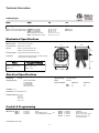
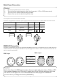
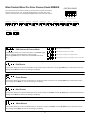
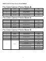
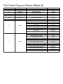
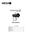
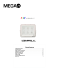
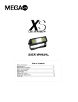
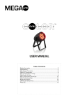
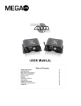
USER MANUAL
Table of Contents
Safety Information……………………………………………………………………………………………. 3
Specifications…………………………………………………………………………………………………….. 4
Main Power Connection…………………………………………………………………………………..5
DMX-512 Connection…………………………………………………………………...……………...…5
Main Control Menu.......................................................................................................... 6
DMX Profile……….................................................................................................................8
Rigging the Fixture……………………………………………………………………………………….…10
Cleaning & Maintenance.............................................................................................10
Parts List............................................................................................................................10
Warranty………………………………………………………………………………………………………..…11
Check that the unit has not been damaged during transport
Protection Against Fire
1.
3.
4.
5.
6.
Maintain a minimum of 1 foot distance from any type of flame.
Replace fuse only with the specified type and rating.
Do Not install the unit to close to a heat source.
Make sure cable are properly secured away from unit movement.
Maximum surface operating temperature 80º.
Protection Against Fire
1.
2.
3.
4.
Disconnect power before servicing.
For connection to main power supply proceed to page 5.
This unit must be earthed. (electronically grounded)
Do not expose unit to rain or moisture.
Protection Against Mechanical Hazards
1. Use safety chain when hanging unit.
2. Use quality clamps or bolts when positioning unit
3. Do not open unit while it is on, risk of electrical shock.
3
Technical Information
Catalog Logic
3000
RGB
30
-xx
Housing
LED Module
Lens Module
Options
15- 15° Lens Kit
30- 30° Lens Kit
60- 60° Lens Kit
25–Penta 25° Lens Kit
45 - Penta 45° Lens Kit
BD-Barn Door
GH-Gel Holder
3000- Pro Color Cannon Black Housing PRGBWA-Penta RGBWA
3001– Pro Color Cannon White Housing TRGB– Tri Colored RGB
TWWA– Tri Colored WWA
RGB– 3 Watt Red, Green, Blue
WWA– 3 Watt White, White, Amber
Mechanical Specifications
DMX Connectors:
3-pin & 5 Pin XLR connectors
Power Connection:
Neutrik Power Con in/Out
Thermal:
Maximum ambient temperature 104°
Maximum surface temperature 140°
9.5””
Fastening System:
Double Mounting Yoke & Security Eye bolt
Accessories:
1 / Edison power head to Blue Power Con cable (included)
1 / White Power Con head (included)
Fixture
8.75””
3.5””
7.75””
Packaged for Shipping
Size: 9.5” x 8.75” x 11.25”
Size: 14” x 10” x 11.5”
Weight: 6 lb
Weight: 7.5 lbs
7.1/16
Electrical Specifications
LED Quantity:
36 or 12
LED Type (Options) :
Penta Colored RGBWA
Tri Colored RGB
Tri Colored WWA
Red, Green, Blue
White, White, Amber
Operating Voltage:
110V-220V50/60 Hz
Ballast:
Electronic
Power Consumption
Watts:
Amps: .
3 Watt Unit
71
91
12 Watt unit
145
1.3
LED Watts: 3 or 12
LED Lifetime: 60 to 100 thousand hours
LED Angle (Options): 15° ( ± 5º )
30° ( ± 5º )
60° ( ± 5º )
P25° ( ± 5º )
P45° ( ± 5º )
Control & Programming
Protocol: DMX 512
DMX Channels: Mode A
Mode P
Mode C
3 Channels
4 Channels
6 Channels
R,G,B,
Dimmer/Strobe, R,G,B
R ,G ,B, Strobe, Macro , Dimmer
Control options: Audio-trigger
4
OR
Mode A
Mode b
Mode C
Mode d
5 Channels
6 Channels
7 Channels
9 Channels
R,G,B,W,A
Dimmer, R,G,B, W, A
Dimmer, R,G,B, W, A, Strobe
Dimmer, R,G,B, W, A, Set
Color, Strobe, Macro
Main Power Connection
Caution!
1.
2.
3.
4.
Do not connect fixture to a dimmer system.
This unit has Auto switching power supply. It will respond to 110V or 220V automatically
This unit must be earthed. (electronically grounded)
Replace fuse only with the specified type and rating.
The occupation of the connection-cable is as follows:
This fixture is equipped with an electronic power supply that will let the unit operate from 100V to 240V from 47Hz to 63Hz
Cable (USA)
Cable (EU)
Pin
110V
220V
Black
Brown
Live
L
L
White
Light Blue
Neutral
N
L
Green
Yellow/Green
Ground
220V
Connection
L
N
L
110V
Connection
L
DMX-512 Connection
The fixture is equipped with 3 pin and 5 pin XLR Sockets for DMX input and output. The sockets are wired in parallel. Only use a
shielded twisted pair cable designed for RS-485 and 3 pin XLR plugs and connectors in order to connect the controller with the
fixture or the fixture with another.
DMX—output
DMX—input
1. Shield
2. Signal (-)
1
2
1
5
2
4
3
1
2
3. Signal (+)
3
1
5
2
4
3
3
Caution!
At the last fixture the DMX signal needs to be terminated with a terminator. Solder a 120
Ohm resistor between the (-) and the (+) signal into a 3 pin XLR plug and plug it in to the
last fixture on the signal run. Pre-manufactured terminator plugs are available for
purchase from your Mega-Lite dealer (HOS-DMXT).
5
Main Control Menu Pro Color Cannon Penta RGBWA
CONTROL BOARD
The control board on the fixture base is your interface to access and control
all the functions on the unit. Its digital display gives you a code view of the
options and functions. The following will explain each function and its options.
Menu
DMX Address
Red Dimmer
Green Dimmer
Blue Dimmer
White Dimmer
1-512
0-15
0-15
0-15
0-15
Sound Program
0-15
Amber Dimmer
0-15
Flash
0-15
Fade Scroll
0-15
Up
Down
Enter
Flash Scroll
Chase Effect
Chase Speed
0-15
0-15
0-15
Sound Program
0-15
Mode A (5 Channels) R,G,B,W,A
DMX Address & Channel Mode
Press Enter to select the mode of operation. Press Enter again
until you have the desired Operating channel mode.
Use the up/down keys to select the required DMX start channel.
Mode b (6 Channels) Dimmer, R,G,B,W,A
Mode C (7 Channels) Dimmer, R,G,B,W,A, Strobe
Mode d (9 Channels) Dimmer, R,G,B,W,A, Pre Set, Strobe, Macro
Red Dimmer
This function allows you to dim the Red LED’s on the whole module. Press Enter use the up/down keys to select desired dimmer
settings. Press Enter to confirm the settings. (15 Steps)
Green Dimmer
This function allows you to dim the Green LED’s on the whole module. Press Enter use the up/down keys to select desired dimmer settings. Press Enter to confirm the settings. (15 Steps)
Blue Dimmer
This function allows you to dim the Blue LED’s on the whole module. Press Enter use the up/down keys to select desired dimmer
settings. Press Enter to confirm the settings. (15 Steps)
White Dimmer
This function allows you to dim the White LED’s on the whole module. Press Enter use the up/down keys to select desired dimmer settings. Press Enter to confirm the settings. (15 Steps)
6
Amber Dimmer
This function allows you to dim the Amber LED’s on the whole module. Press Enter use the up/down keys to select desired dimmer settings. Press Enter to confirm the settings. (15 Steps)
Flash
This function allows you to strobe the LED’s in White color. Press Enter use the up/down keys to select desired flash settings.
Press Enter to confirm the settings.
Fade Scroll
This function allows you to fade the LED’s from one color to another. Press Enter use the up/down keys to select desired fade
speed settings. Press Enter to confirm the settings.
Flash Scroll
This function allows you to change the LED’s from one color to another. Press Enter use the up/down keys to select desired
color change speed settings. Press Enter to confirm the settings.
Chase Effect
This function allows you to select different chase patterns. Press Enter use the up/down keys to select desired chase settings.
Press Enter to confirm the settings.
Chase Speed
This function allows you to select the speed of the chase that was selected on the Chase Effect . Press Enter use the up/down
keys to select desired chase speed settings. Press Enter to confirm the settings.
Sound Chase
This function allows you to select the chase pattern that will be triggered via audio. Press Enter use the up/down keys to select
desired Chase settings. Press Enter to confirm the settings.
Sound Flash
This function allows you to select the flash pattern that will triggered via audio. Press Enter use the up/down keys to select desired dimmer settings. Press Enter to confirm the settings.
Sound Sensor
This function allows you to select the sensitivity of the audio sensor. Press Enter use the up/down keys to select desired dimmer
settings. Press Enter to confirm the settings.
7
DMX Profile Pro Color Cannon Penta RGBWA
Pro Color Cannon Penta Mode A
DMX Chanel
1
2
3
4
5
Function
LED Color
LED Color
LED Color
LED Color
LED Color
Description
Red LED intensity
Green LED Intensity
Blue LED Intensity
White LED Intensity
Amber LED Intensity
Value
0-255
0-255
0-255
0-255
0-255
Pro Color Cannon Penta Mode b
DMX Chanel
1
2
3
4
5
6
Function
Dimmer
LED Color
LED Color
LED Color
LED Color
LED Color
Description
Dimmer Off to Full
Red LED intensity
Green LED Intensity
Blue LED Intensity
White LED Intensity
Amber LED Intensity
Value
0-255
0-255
0-255
0-255
0-255
0-255
Pro Color Cannon Penta Mode C
DMX Chanel
1
2
3
4
5
6
Function
Dimmer
LED Color
LED Color
LED Color
LED Color
LED Color
7
Strobe
Description
Dimmer Off to Full
Red LED intensity
Green LED Intensity
Blue LED Intensity
White LED Intensity
Amber LED Intensity
No Function
Strobe (slow to fast)
No Function
Pulse on to off (slow to fast)
No Function
Pulse off to on (slow to fast)
No Function
Random Strobe (slow to fast)
8
Value
0-255
0-255
0-255
0-255
0-255
0-255
0-9
10-57
58-59
60-108
109-110
111-159
160-161
162-255
Pro Color Cannon Penta Mode d
DMX Chanel
1
2
3
4
5
6
7
Function
Dimmer
LED Color
LED Color
LED Color
LED Color
LED Color
Preset Color
8
Strobe
9
Macro
Description
Dimmer Off to Full
Red LED intensity
Green LED Intensity
Blue LED Intensity
White LED Intensity
Amber LED Intensity
PreSet Color
No Function
Strobe (slow to fast)
No Function
Pulse on to off (slow to fast)
No Function
Pulse off to on (slow to fast)
No Function
Random Strobe (slow to fast)
No Function
Color fade (slow to fast)
Color Snap (slow to fast)
Pastel Color Snap (slow to fast)
Color On/Off (slow to fast)
Color Snap Off (slow to fast)
Color Pulse On to Off (slow to fast)
Color Pulse Off to On (slow to fast)
Random Color Snap (slow to fast)
Strobe Color (slow to fast)
Strobe Random Color
Color Chase (slow to fast)
9
Value
0-255
0-255
0-255
0-255
0-255
0-255
1-255
0-9
10-57
58-59
60-108
109-110
111-159
160-161
162-255
0-1
2-15
16-31
32-47
48-63
64-79
80-111
112-127
128-159
160-207
208-239
240-255
Rigging the fixture
Caution!
1.
2.
3.
4.
The installations must be carried out by an authorized dealer or trained professional.
Unit may cause severe injures if you have doubts concerning the safety do not install.
Unit is to be 24inches away from flammable materials (decoration material)
Use high quality installation equipment to hang unit.
When rigging a unit it is very important that you follow common safety procedures. Rigging requires extensive experience including but not limited to calculating working loads, material being used and periodic safety inspections. If you lack these qualifications, do not attempt the installation yourself, instead use a professional structural rigger.
When rigging the unit always be secured with a secondary safety attachment. The installation location of the projector has got to
be built in the way that it can hold 10 times the weight for 1 hour with out any harming. Installation should be checked at least
one time a year by a skilled person.
Cleaning and maintenance
Installation Maintenance: The operator has to make sure that the unit is operating safely and has the installations and electronics checked by an expert every 2 years.
The following points have to be considered during the inspection:
1) All screws used for installing the device or part of the device have to be tightly connected and must not be corroded.
2) There must not be any deformations on the housing, fixation and installation spots (ceiling, suspension, trussing).
3) The electronic power supply cables must not show any damages, material fatigue (e.g. porous cables) or sediments. Further
instructions depending on the installation spot and usage have to be adhered by a skilled installer and any safety problems
have to be removed.
Note: There is no serviceable parts inside the device except for the LED’s. Maintenance and service operations are to be carried
out by authorized dealers.
Replacing the fuse: Only replace the fuse with the same type and rating.
Replacing the power cable: If the power cable of this device becomes damaged, it has to be replaced by authorized dealers or
trained professional only.
Should you have further questions , please contact your dealer.
Parts List
9056
Quad Cannon Road Case
3000-pcbp
Penta Main PCB card
3000-psp
Penta Power Supply
4000-dis
Display
4000-fh
Fuse Holder
3000-fan
Fan
3000-GH
Gel Holder (accessory)
3000-BD
Barn Boor (accessory)
ETL LISTED
STAGE AND STUDIO
LUMINAIRES
4001502
CONFORMS TO UL STD 1573
10
Warranty Conditions
• Unless otherwise stated in writing, your product is covered by a one year parts and labor limited warranty.
• LEDs are not guaranteed to match in color temperature our output.
• It is the owner’s responsibility to furnish receipts or invoices for verification of purchase, date, and reseller or distributor. If
purchase date cannot be provided, date of manufacture will be used to determine warranty period.
• GOODS RETURNED UNDER WARRANTY MUST FOLLOW THE PROPER AUTHORIZATION PROCEDURE AND MUST
BE ACCOMPANIED BY A COPY OF THE ORIGINAL INVOICE
• Goods repaired under warranty will be returned to the owner with the freight prepaid by MSI via the most economical
means of shipment
• REPAIR OR REPLACEMENT AS PROVIDED FOR UNDER THIS WARRANTY IS THE EXCLUSIVE REMEDY OF THE
CONSUMER. MEGA SYSTEMS INC. MAKES NO WARRANTIES, EXPRESS OR IMPLIED, WITH RESPECT TO ANY
PRODUCT, AND MEGA SYSTEMS SPECIFICALLY DISCLAIMS ANY WARRANTY OF MERCHANTABILITY OR FITNESS
FOR A PARTICULAR PURPOSE. MEGA SYSTEMS SHALL NOT BE LIABLE FOR ANY INDIRECT, INCIDENTAL OR
CONSEQUENTIAL DAMAGE, INCLUDING LOST PROFITS, SUSTAINED OR INCURRED IN CONNECTION WITH ANY
PRODUCT OR CAUSED BY PRODUCT DEFECTS OR THE PARTIAL OR TOTAL FAILURE OF ANY PRODUCT
REGARDLESS OF THE FORM OF ACTION, WHETHER IN CONTRACT, TORT (INCLUDING NEGLIGENCE), STRICT
LIABILITY OR OTHERWISE, AND WHETHER OR NOT SUCH DAMAGE WAS FORESEEN OR UNFORESEEN.
• Warranty is void if the product is misused, damaged, modified in any way, or for unauthorized repairs or parts. This
warranty gives you specific legal rights, and you may also have other rights which vary from state to state.
Mega-Lite
5718 Kenwick St
San Antonio, TX 78238
Ph 210-684-2600 Fax 210-855-6279
www.mega-lite.com / [email protected]