1
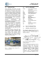
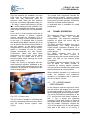
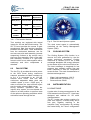
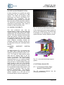
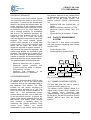
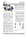
DISTRIBUTION STATEMENT
NATURA DOCUMENTO
RISTRETTO
ARCHIVIO
DOCUMENT NUMBER:
REV.:
CIRA-CF-09-1144
1
PROJECT
PROGETTO
COND_LMSA
PROGRESSIVO DI ARCHIVIO
/CIRA/PTUN
JOB
COMMESSA
3090510000
NO. OF PAGES
WP
9051
DELIVERABLE
3+16
0047
TITLE
CIRA PT-1 USER MANUAL
PREPARED
PREPARATO
REVISED
VERIFICATO
APPROVED
APPROVATO
Izzo Carmelo
(PTUN)
Izzo Carmelo
(PTUN)
Izzo Carmelo
(PTUN)
DATE/DATA
DATE/DATA
14/09/2009
14/09/2009
DATE/DATA
14/09/2009
AUTHORIZED
AUTORIZZATO
Vecchione Ludovico
(SIAE)
DATE/DATA
14/09/2009
BY THE TERMS OF THE LAW IN FORCE ON COPYRIGHT, THE REPRODUCTION, DISTRIBUTION OR USE OF
THIS DOCUMENT WITHOUT SPECIFIC WRITTEN AUTHORIZATION IS STRICTLY FORBIDDEN
A NORMA DELLE VIGENTI LEGGI SUI DIRITTI DI AUTORE QUESTO DOCUMENTO E' DI PROPRIETA' CIRA E NON POTRA'
ESSERE UTILIZZATO, RIPRODOTTO O COMUNICATO A TERZI SENZA AUTORIZZAZIONE
I
DOCUMENT NUMBER:
REV.:
CIRA-CF-09-1144
1
TITLE:
CIRA PT-1 USER MANUAL
ABSTRACT:
The present document describes the characteristics and the procedures of the CIRA Transonic Wind
Tunnel PT-1. The PT-1 performance and the main dimension are described. The PT-1 auxiliary
systems have been described.
The time schedule requirements and the support requirement have been also outlined in order to give
a guideline to PT-1 test organization and facility reservation.
Furthermore the CIRA location and nearest lodging options have been presented.
AUTHORS:
Izzo Carmelo;Martire Luigi
APPROVAL REVIEWERS:
Izzo Carmelo
APPROVER
Izzo Carmelo
AUTHORIZATION REVIEWERS:
Vecchione Ludovico
AUTHORIZER
Vecchione Ludovico
II
DOCUMENT NUMBER:
REV.:
CIRA-CF-09-1144
1
DISTRIBUTION RECORD:
DEPT
NAME
*
DEPT
NAME
*
Gruppo Ptun
SIAE
Vitiello Domenico
SIAE
Melluso Pasquale
* PT = PARTIAL
A = ALL
III
DOCUMENT NUMBER
CIRA-CF-09-1144
IDENTIFICATIVO
REV.
1
REVISION LIST
LISTA DELLE REVISIONI
REV.
DESCRIPTION
DATE
EDITOR
0
Sostituisce CIRA-UM-04-300
09/09/2009
C. Izzo
1
Aggiornata Lista Contact Point
14/09/2009
C. Izzo
CIRA-CF- 09-1144
PT1 USER MANUAL
SUMMARY
1.0
INTRODUCTION...........................................................................................3
2.0
LIST OF ACRONYMS...................................................................................3
3.0
FACILITY DESCRIPTION.............................................................................3
3.1
4.0
4.1
GENERAL DESCRIPTION....................................................................................3
TUNNEL OPERATION .................................................................................4
PT-1 AERODYNAMIC PERFORMANCE.............................................................4
5.0
TEST SECTION DETAILS ............................................................................5
6.0
FAN SYSTEM ...............................................................................................6
7.0
COOLING SYSTEM......................................................................................6
8.0
INSTRUMENTATION....................................................................................6
8.1
WAKE RAKE ........................................................................................................6
8.2
PRESSURE MEASUREMENT INSTRUMENTATION.........................................7
8.3
OTHER INSTRUMENTATION.............................................................................8
8.4
VIRTUAL INSTRUMENTATION .........................................................................9
8.5
IMAGING CAPABILITY.......................................................................................9
8.6
MODEL SUPPORT SYSTEM (MSS) .....................................................................9
8.7
INTERNAL BALANCES .......................................................................................9
8.7.1 3 Component Strain Gage Balance Characteristics ..............................................9
8.7.2 6 Component Strain Gage Balance Characteristics ............................................10
9.0
9.1
9.2
9.3
10.0
10.1
10.2
AUXILIARY SYSTEMS ...............................................................................10
AIR SUPPLY SYSTEM........................................................................................10
CIRCUIT EXHAUST ...........................................................................................11
PLENUM EXHAUST ...........................................................................................11
FACILITY MANAGEMENT
SYSTEM..................................................11
TUNNEL CONTROL SYSTEM ...........................................................................11
DATA ACQUISITION AND ELABORATION SYSTEM ....................................12
11.0
COMPUTER PLATFORM...........................................................................13
12.0
TEST GENERAL ARRANGEMENT ...........................................................13
13.0
PT-1 OPERATING TEAM ...........................................................................13
14.0
PERSONNEL SAFETY ISSUES.................................................................13
14.1
14.2
HAZARDS............................................................................................................13
PROTECTIVE EQUIPMENTS.............................................................................14
Page 1 of 15
CIRA-CF- 09-1144
PT1 USER MANUAL
14.3
EMERGENCY PROCEDURES............................................................................14
15.0
CIRA SITE LOGISTIC.................................................................................14
16.0
PT-1 TEST REQUEST PROCEDURE ........................................................14
17.0
CONTACT POINT.......................................................................................14
18.0
REFERENCES............................................................................................15
Page 2 of 15
CIRA-CF- 09-1144
PT1 USER MANUAL
1.0
INTRODUCTION
Since September 1998 CIRA, the Italian
Aerospace Research Centre, has entered
into operation a Transonic Wind Tunnel
PT-1 with the aim to support industrial and
research programmes with a versatile and
high flow quality aerodynamic testing
platform, over a wide speed range, for a
variety of small scale test articles. In May
2000 CIRA has been granted membership
in the Supersonic Tunnel Association,
International (STAI).
This document describes the wind tunnel
technical
characteristics
and
performances, its instrumentation and the
typical operative procedures.
The CIRA PT-1 is equipped with complete
tunnel instrumentation for aerodynamic
measurements. CIRA test engineers are
available for measurement support and
data
interpretation.
Nevertheless
customers are free to operate, within their
individual agreement with CIRA, their own
instrumentation.
The facility is located in Capua (CE), Italy
about 50 km north of Naples. The
Transonic Wind Tunnel is part of a brand
new complex which includes ground
testing facilities and dedicated service
utilities making up the Italian Aerospace
Research Centre. The picture in Fig.1
shows a view of the facility.
2.0
LIST OF ACRONYMS
CIRA
CL
CS
DAS
FMS
System
HX
HW
PT-1
MSS
SW
TS
UPS
Supply
V
VI
WT
Centro Italiano Ricerche
Aerospaziali
Wind Tunnel Centre Line
Cooling System
Data Acquisition System
Facility Management
Heat Exchanger
Hardware
Pilot Tunnel 1
Model Sting Support
Software
Test Section
Uninterruptable Power
Velocity
Virtual Instrumentation
Wind Tunnel
3.0
FACILITY DESCRIPTION
3.1
GENERAL DESCRIPTION
The Transonic Wind Tunnel PT-1 is a
closed-circuit, pressurised wind tunnel. A
sketch of the PT-1 functional layout is
shown in Figure 2.
Fig.2: Transonic Wind Tunnel PT-1
functional layout
Fig. 1: Transonic Wind Tunnel PT-1 –
General Overview
The PT-1 has two drive systems: a fan, for
continuous subsonic tests, and an air
compressed system, for intermittent
transonic and supersonic tests. The facility
is equipped with two nozzle blocks: a
convergent nozzle, for Mach numbers
below 1.1, including fan continuous
operations, and a convergent-divergent
nozzle for intermittent operations at M =
1.4.
Page 3 of 15
CIRA-CF- 09-1144
PT1 USER MANUAL
Two test sections are available: one with
solid walls for subsonic tests, and the
other one with perforated walls for
transonic tests. Both the test sections
have top and bottom adjustable walls (α=
+ 0.5 deg.). Lateral wall inserts for 2D and
half - model testing are also available. The
inserts are equipped with bottom and side
walls optical windows for flow visualization
tests.
Up to the 3% of the injected mass flow is
removed through a plenum exhaust
system, whereas the remaining 97% is
removed through a circuit exhaust system.
In this way, it is possible both to control
the speed at high Mach numbers (M > 0.8)
and to achieve the desired flow qualities in
the test section. In the Mach number
range between 0.4 and 0.8 the test section
speed is controlled via the 2nd throat,
located downstream the test section.
Furthermore, Mach trim flaps allow
performing a fine control of the Mach
number. The 2nd throat and a set of
acoustic baffles allow reducing the noise
level in test section.
Finally, the facility is equipped with two
data acquisition systems, dedicated to the
control of the facility parameters and to the
acquisition of pressures, temperatures and
other analog signals.
The control room equipment includes the
video camera monitors, operator console
and the engineering and data acquisition
hosts which provide complete information
about the test and model conditions.
A dedicated area is available for model
preparation
4.0
TUNNEL OPERATION
The maximum speed achievable in the
IWT depends
upon the
selected
configuration. The maximum stagnation
pressure at which the tunnel may be
operated is 1.75 bar.
The Mach number is variable from 0.4 to
approximately 1.05 using convergent
nozzle blocks. Operation at Mach 1.4 is
achieved
using
convergent/divergent
nozzle blocks.
For Mach numbers from 0.4 to
approximately 0.8 Mach number is
controlled using the second throat and the
Mach trim flap on the second throat
centerbody.
For Mach numbers between 0.8 and 1.05
and at Mach 1.4, Mach number is
controlled by varying plenum pressure
using the plenum exhaust flow system with
the second throat at a fixed position.
While subsonic operation is in continuous
mode, the transonic and supersonic
operation is intermittent with a maximum
run time of about 130 sec.
4.1
PT-1 AERODYNAMIC
PERFORMANCE
Fig.3: PT-1 Control room
The WT circuit is located in a building that
hosts the operating team and users offices
and the facility control system room
(Fig.3).
In the transonic and the supersonic tests,
the test section wall angles have been set
to a diverging angle of 0.25 deg., to control
the boundary layer growth along the walls.
The main performance parameters of the
PT-1 wind tunnel have been included in
tab. 1. Fig. 4 shows the operating
envelope of the wind tunnel in terms of
achievable Mach & Reynolds for both 3D
and 2D models. Reference lengths are
10% of the square root of the test section
area and a 2D chord of 10 cm.Fig. 5
Page 4 of 15
CIRA-CF- 09-1144
PT1 USER MANUAL
shows the Mach-P0 envelope with
Reynolds curves for the 2D reference
length.
1.15
1.10
1.05
1.00
0.95
Mach Number
0.90
3.500.000
q = 2.500 [Pa]
q = 10.000 [Pa]
q = 25.000 [Pa]
q = 50.000 [Pa]
Lref (3D) = 0,040 [m]
Re
3.000.000
q = 5.000 [Pa]
q = 15.000 [Pa]
q = 30.000 [Pa]
q = 60.000 [Pa]
q = 7.500 [Pa]
q = 20.000 [Pa]
q = 40.000 [Pa]
Lref (2D) = 0,1 [m]
0.85
0.80
0.75
0.70
0.65
0.60
Model Length
0.55
2.500.000
Rotation Centre
0.50
0.45
2.000.000
0.40
0
100
200
300
400
500
Test section length (mm)
1.500.000
1.000.000
Fig. 6: Empty tunnel Mach
longitudinal distribution
500.000
0
0,0
0,1
0,2
0,3
0,4
0,5
0,6
0,7
0,8
0,9
1,0
1,1
1,2 M 1,3
1,4
1,5
Fig. 4: PT-1 operating envelope –
Reynolds vs. Mach number
5.0
180
Po [KPa]
170
160
150
140
130
120
110
100
Lref = 0,1 [m]
Re = 1.250.000
Re = 2.250.000
90
Re = 500.000
Re = 1.500.000
Re = 2.500.000
Re = 750.000
Re = 1.750.000
Re = 2.750.000
Re = 1.000.000
Re = 2.000.000
Re = 3.000.000
80
0
0,1
0,2
0,3
0,4
0,5
0,6
0,7
0,8
0,9
1
1,1 M 1,2
1,3
1,4
number
1,5
Fig. 5: PT-1 operating envelope – Total
pressure vs. Mach number
TEST SECTION DETAILS
The facility is equipped with two test
sections, one for subsonic tests and the
second for transonic/supersonic tests with
perforated walls (60° inclined holes, 6.3%
porosity). Both test sections have floor and
ceiling adjustable walls (α = + 0.5 deg.)
In
the
intermittent
injection-driven
operation mode, the Mach number set
point is in the range between 0.4 and 0.8,
reached via the 2nd throat adjustment,
while for higher Mach numbers the set
point is reached via mass flow removal (up
to 3% of the overall circuit mass flow) on
the test section perforated walls. The
different test section features are listed in
Tab. 1.
The Mach number distribution in the empty
test section has been measured during
facility calibration using a centreline static
pipe.
The mach distribution is shown in fig. 6.
Fig. 7: Solid wall test section
Page 5 of 15
600
CIRA-CF- 09-1144
PT1 USER MANUAL
Test section
Parameter
Size (w,h,l)
Subsonic
Transonic /
Supersonic
350x450x600 350x450x600
Walls
Solid
Perforated
6% porosity
Contraction
ratio
10:1
10:1
Mach
number
0.1 - 0.37
0.35 - 1.1
1.4
Tab. 1: Test section features
Test sections are equipped with lateral
inserts for 2D and half-model testing. The
2D TS insert provides the means to gain
aerodynamic data from articles spanning
between the side walls. Three assemblies
form the mechanical hardware: one far
and one near side wall assembly (nearest
respectively furthest to the control room)
plus one floor assembly. Each of the side
wall assembly consists of a rigid base
frame to which a turn table together with a
machinery and drive components is
attached.
6.0
FAN SYSTEM
The fan (Fig. 8) provides the motive power
to the wind tunnel during continuous
subsonic operations at Mach numbers up
to 0.4. It is connected to an 132 kW
external drive motor, and has both
continuous adjustable blade pitch and
variable speed (n max = 3000 rpm), in
order to achieve the most efficient layout
over the entire subsonic Mach range.
During transonic operations with the
injector drive system, the rotor blades ere
locked in a fixed position to perform tests
of the optimum operating conditions which
minimizes losses through the fan.
Fig. 8: Fan Unit and injectors system
The wind tunnel speed is automatically
controlled via the Facility Management
System (FMS).
7.0
COOLING SYSTEM
The Cooling System (CS) function is to
remove the heat generated by the fan
during continuous operations. Cooling
water flow is variable, up to 5 lt/s. A heat
exchanger dissipates the energy delivered
to the stream by the wind tunnel drive fan.
The heat exchanger is designed for low
pressure loss, spatially uniform flow and
small variations in bulk air temperature
across its face. The main characteristics of
the heat exchanger are:
-
8.0
Water inlet temperature: 12.8°C
Water flow rate: 3.01l/sec(2.11)
Removed heat: 50 kW
INSTRUMENTATION
8.1 WAKE RAKE
A wake rake for drag measurement in the
CIRA transonic wind tunnel PT-1 has been
designed and realised for 2D airfoil
characterisation.
The PT-1 wake rake system consists of a
main rear support, a central body and a
fore part, together resulting in the
complete “long” configuration. By omitting
the central body, the “short" configuration
Page 6 of 15
CIRA-CF- 09-1144
PT1 USER MANUAL
is obtained, corresponding to the
maximum allowable rear position (Fig. 9).
Fig. 9: “Long” and “Short” configurations
Central body is an interchangeable
interface element between the fore body
and the rear support. By substituting (with
a new piece) or omitting this part it is
possible to vary the longitudinal position of
the probe array. Central body can be
installed or removed from the wake rake
system without removing probe connection
tubes. A removable cover panel located on
one side, in the central zone, allows the
access to the central internal vane,
provided for tube driving.
Rear support and fore body are the base
elements of the wake rake system. Rear
support is the interface with wind tunnel
arc sector support system; its shape has
been designed in order to satisfy the
installation requirement, and reproduces,
where possible, the existing conical arc
sector.
The fore body is the core of the wake rake
system, designed to allow the installation
of 64 total pressure probes and four
supports for static pressure probes. It
consists of 3 subcomponents, 2 of them
fixed together after machining and
resulting in a “main fore element”; the third
one is a removable cover element allowing
the access to the internal cavity.
Fore body central zone has a cuneiform
shape, varying from a rectangular rear end
section 16 mm wide, to a forward section
with a 3.0 mm diameter rounded shape.
Top and bottom fore zones have a
rectangular longitudinal section, 6.0 mm
thick; an internal cavity 2.0 mm wide has
been provided, corresponding to the
minimum dimension that allow the
installation of total pressure probes and
the routing of the relevant connection
tubes. The need for a larger central zone
stems from the necessity to install 46 Pitot
probes: 21 of them are placed along the
central longitudinal section, 19 along 2
lines placed symmetrically at a distance of
2.5 mm from the central section, and 6
along 2 more lines placed symmetrically at
a distance of 5 mm from the central
section.
The pitot probe distribution allows to
capture the whole wake event at incipient
stall conditions.
Fig. 10: Wake Rake Installed on PT-1
model
support
system
–
“long”
configuration
8.2 PRESSURE
MEASUREMENT
INSTRUMENTATION
Pressure is the main parameter measured
in PT-1. The facility is equipped with two
pressure measurement systems.
Page 7 of 15
CIRA-CF- 09-1144
PT1 USER MANUAL
The first system is part of the Master
Control System (MCS), dedicated to the
control of the facility.
This system is equipped with two absolute
pressure
transducers,
for
the
measurement of total pressure in stilling
chamber and static pressure in plenum
chamber, and two differential pressure
transducers,
to
measure
dynamic
pressures.
The table 2 shows the characteristics of
these transducers which are critical to
assess the facility operation condition.
Parameters from those transducers may
be used for understanding of the
aerodynamic process inside major facility
components.
Measured
Parameter
FS
(Bar)
Accuracy
%F.S.
Abs.Error
(Bar)
Total pressure in
stilling chamber
2
0.05
1E-3
Static pressure
in plenum
chamber
2
0.05
1E-3
Dynamic
Pressure (low
range)
0.35
0.05
2E-4
Dynamic
Pressure (high
range)
1.4
0.05
7E-4
Tab. 2: MCS
characteristics
Pressure
Measured
Parameter
FS
(PSI)
Accuracy
%F.S.
Abs.
Error
(Bar)
Mode
Pt and PS
in stilling
chamber
30
0.05
1E-03
Differential
Ps on the
centerline
15
0.05
5E-04
Differential
Wall static
pressures
30
0.05
1E-03
Differential
Ambient
pressure
45
0.01
3E-04
Absolute
Tab. 3: PSI 8400 pressure transducers
characteristics
Transducers
The second system is the PSI 8400,
manufactured by Pressure System. PSI
8400 is part of the test data acquisition
system. Pressures data collected duringA
run may be acquired by means of the PSI
8400 (Fig. 11). The pressure transducers
characteristics are shown in tab. 3.
Fig. 11: PSI 8400 system
8.3 OTHER INSTRUMENTATION
Other available instruments
characterization are:
−
−
for
flow
Hot Wire
Flow Angularity Probe
Page 8 of 15
CIRA-CF- 09-1144
PT1 USER MANUAL
8.4 VIRTUAL INSTRUMENTATION
In case necessary for a specific test, other
instruments can be connected to FMS
system. The FMS will recognize these
instruments as Virtual Instruments (VI).
Particularly, the connection can be
performed linking physically and logically
the instrument to Data Acquisition System.
The logical link is performed to the Virtual
Instrument Communicator Task, which is
located on Data Acquisition Host.
8.5 IMAGING CAPABILITY
Fig. 12: rear sting model support system
The test performed can also be
documented by means of video and still
imaging reporting. Both optical and digital
imaging may be recorded during or after
the run. Two video cameras are positioned
inside the plenum, looking at the model
from different viewpoints. The video image
is displayed on the monitors in the control
room. Different recording formats are
available. Particular customer request can
be discussed during the meetings before
the test.
A new motorized model support system is
going to be installed soon. A pictorial view
is provided in the following fig. 13. This
system has been entirely design by CIRA.
8.6 MODEL
(MSS)
SUPPORT
SYSTEM
The Model Support (Fig. 12) consists of an
arc sector with a sting pod that can be
manually positioned at pitch angles of 0°,
+/-2°, +7.5° and 15°. Both the arc sector
itself and the leading edge of the arc
sector are removable to allow testing with
various geometries. The initial leading
edge geometry is a 4 to 1 elliptical shaped
nose and a 20° included angle taper. The
sting pod has an instrumentation passage
large enough to hold up to 50 pressure
tubes and pass the tube directly into the
strut. The pod may be connected to a sting
for conventional model testing and to a 4
cm diameter centreline pipe for static
pressure measurements. The following
Fig. 13 shows the current model support
system installed for a 3D test on an
Unmanned Space Vehicle configuration.
Fig. 13 – new motorized model support
system
8.7 INTERNAL BALANCES
8.7.1 3 Component Strain Gage
Balance Characteristics
The 3C component balance has the
following characteristics.
Page 9 of 15
CIRA-CF- 09-1144
PT1 USER MANUAL
Component
name
Symbol
Full Scale
Axial force
Fx
240 N
Normal force
Fz
1500 N
Pitching
moment
My
60 Nm
The 3C balance has been designed and
built in order to guarantee on each
component a measurement accuracy of
0.1% of the relevant above listed full scale
values. An overload capacity of 2 times
load capacity has been provided. The 3C
balance has been used in several test
campaign.
8.7.2 6 Component Strain Gage
Balance Characteristics
The 6C component balance has the
following characteristics.
Component
name
Symbol
Full Scale
Axial force
Fx
160 N
Side force
Fy
350 N
Normal force
Fz
1000 N
Mx
9.0 Nm
My
40.0 Nm
Mz
30.0 Nm
Rolling
moment
Pitching
moment
Yawing
moment
The 6C balance is designed in order to
guarantee on each component a
measurement accuracy of 0.1% of the
relevant above listed full scale values. The
balance has overload capacity of 2 times
the load capacity. The following Fig. 14
shows the internal balance acquisition unit
which has been designed and built at
CIRA.
Fig. 14: Internal balances acquisition unit
9.0
AUXILIARY SYSTEMS
The auxiliary systems for PT-1 include the
air supply system, circuit exhaust system
and plenum exhaust system described in
the following subsections.
9.1 AIR SUPPLY SYSTEM
The air supply system provides air to drive
the tunnel injector and the plenum ejector
for intermittent operations in the transonic
range. The system includes an air
compressor system, high pressure air
storage tanks and piping to deliver air to
the injector nozzles and the plenum
ejectors.
The
air
supply
system
characteristics are:
-
-
Pressure at injector: 17 bar (absolute)
Maximum injector mass flow rate: 21
kg/sec
Maximum plenum ejector flow rate: 5
kg/s
Run time at Mach 1.4: 130 sec
Minimum air temperature -10°C
Maximum
temperature
excursion
during a run: +/- 10°C from tunnel
ambient
Maximum storage repump time: 30
minutes
Page 10 of 15
CIRA-CF- 09-1144
PT1 USER MANUAL
9.2 CIRCUIT EXHAUST
The function of the circuit exhaust system
is to remove the air added to the circuit by
the injector. To overcome the aerodynamic
losses in the piping and exhaust stack, the
tunnel pressure at the exhaust location
must be somewhat above ambient in order
to be driven out of the circuit without the
aid of external pumping. To accomplish
this at the PT-1 transonic operation, the
minimum tunnel pressure will be in the
range from 1.25 to 1.5 bars. The actual
value will be determined from the pilot test
program. The circuit exhaust system
control valves operate in a closed loop
control mode. If the tunnel pressure rises
above the set point, the valves open
slightly as required to release pressure. If
the pressure falls below the set point, the
valves close slightly as required to gain
pressure. The exhaust air is drawn out of
the tunnel through a perforated section,
collects in a plenum and flows through four
exhaust ducts to the circuit exhaust stack.
The exhaust system characteristics are:
-
Maximum mass flow rate: 21 kg/sec
Maximum system pressure loss
(control valves fully open): < 0.20 bars
Exit pressure: 1.0 bars
Minimum inlet pressure: to be
determined from PT-1 operation
9.3 PLENUM EXHAUST
The plenum exhaust system (PES) is used
to extract up to 3% of the wind tunnel
mass flow through the perforated walls of
the transonic test section. The PES
controls the test section conditions at
transonic Mach numbers up to 1.05. The
PES trims the test section conditions at
Mach 1.4.
Two symmetrically placed
exhaust ducts are used, one on each side
of the test section plenum, to reduce the
impact of the plenum exhaust flow on the
test section flow quality. Each exhaust
duct contains a butterfly valve for
controlling the plenum pressure using
closed
loop
control.
An
ejector
downstream of the control valves pumps
the plenum exhaust to the exhaust stack
at atmospheric pressure. The ejector is
driven by the air supply system. The
plenum exhaust system characteristics
are:
- Maximum wall flow removal rate: 1.9
kg/sec
- Minimum plenum pressure: 0.47 bar
- Maximum ejector primary flow: 4.73
kg/sec
- Ejector primary air pressure: 15.4 bar
10.0
FACILITY MANAGEMENT
SYSTEM
The CIRA PT-1 wind tunnel is equipped
with two systems managing data coming
from the field:
-
Control System (CS)
Data Acquisition System (DAS)
MMI
PC
DAS
PC
ENG
PC
Manual
Console
Elsag Bailey
Data Highway
I/O Boads
Dedicated
Control
System
PSI
Unit
AI Boards
Air Supply
System
Instrumentation
Test
Instrumentation
Allen Bradley
SLC500
PLC
INFI90
DCS
(3 Processors)
I/O Boards
Circuit Exhaust
Instrumentation
I/O Boards
Facility
Instrumentation
PT-1 Wind Tunnel
Fig. 15: Facility Management System
10.1 TUNNEL CONTROL SYSTEM
CS gets data from the field in order to
control the facility (see fig. 16).
The Master Control System (MCS) is a
digital control system which consists of a
run console, servo controllers and
instrumentation. The process is controlled
by the MCS. The MCS includes a ELSAG
BAILEY INFI-90 and LAN 90 control
system.
Page 11 of 15
CIRA-CF- 09-1144
PT1 USER MANUAL
STORAGE
THANKS
Dedicated
Controller
INFI90
Controller
INFI90
Controller
Pressure
INFI90
Controller
Pressure
Fan
RPM
Air Supply System
Blade Pitch
Position
Injection System
Ejection System
EXHAUST
DUCT
Fan
EXHAUST
DUCT
Venturi
Plenum Exhaust
SLC500
PLC
INFI90
Controller
Pitot Sensor
Circuit Exhaust
2n d Throat Walls
Test
Chamber
Mach Trim Flaps
MTF and 2nd Throat
Position
operations
of
test
and
device
configuration, on-line pressure transducers
calibration, data acquisition recording and
visualization. Furthermore, the integrator
coordinates the entire process of model
attitude positioning and data recording on
event, for Pitch & Pause or Pitch Sweep
test modes.
In Fig. 17 the overall system configuration
is illustrated. The integrated hardware
devices are:
INFI90
Controller
Fig. 16:
Diagram
Control
System
functional
The Control System has two types of
control loops, that process control loops
and the positioning control loops. Control
loops are used to control the tunnel,
injector and ejector pressures.
Position control is used for second throat
side walls and Mach trim flaps. Speed and
blade pitch control is used for fan control.
Tunnel fill control is used to pressurize the
tunnel before running. Tunnel vent control
is used to reduce the tunnel pressure.
10.2 DATA
ACQUISITION
ELABORATION SYSTEM
AND
The PT-1 Data Acquisition System (DAS)
is fully dedicated to the Test Article
measurements.
DAS gets data related to the specific test
to be performed in the wind tunnel; data
will come either from the model in the test
section or from the tunnel itself.
For 2D testing, a modular integrated
hardware has been designed and built.
Three measurement systems and a turn
table controller for the test article (model)
attitude positioning have been integrated.
Each of these devices is controlled by a
software module, running on a PC called
“controller”, that operates both as
subsystem supervisors and data servers.
Another
software
module,
called
“integrator”, running on a remote PC, is
connected to each server PC through a
LAN link and works as client of the
different
servers.
The
integrator
centralizes, respect to the operator, the
(a) An electronically pressure scanning
system (PSI8400) which acquires
about 250 pressure measurements on
the model and on the wind tunnel
internals. This system is connected to
the controller PC through a IEEE488
link.
(b) A high precision barometer (DPI740)
for the precise measurement of the
atmospheric pressure. This device is
connected to the controller PC through
a RS232 link.
(c) A dual sensor (RUSKA6222) for high
precision Mach number measurement.
This device is connected to the
controller PC through a RS232 link.
(d) A computer based turn table system
for model attitude positioning. This
device is connected to the controller
PC through a RS232 link.
Fig. 17: PT-1 Data Acquisition System
Configuration
Page 12 of 15
CIRA-CF- 09-1144
PT1 USER MANUAL
11.0
COMPUTER PLATFORM
The host hardware platform is based on a
PC network running Microsoft Windows
XP. The communication is assured by an
100 Mbit Ethernet LAN. The interface to
the PLC based low-level control systems
consists of an industrial Ethernet LAN.
Moreover, the PT-1 computer network
consists of the following PC:
−
−
−
File server
Tunnel control host
Test automation host
of
the
following
equipment:
−
−
data
acquisition
Pressure System
Balance System
The following devices are also available:
−
−
B/W Laser printer
Video system
All systems are fed through UPS supply.
12.0
TEST GENERAL
ARRANGEMENT
The facility in principle runs on a single
shift of 8 hours per day but, on request,
different working time can be contracted.
The time required for a run is strongly
affected by the measurements to be
performed after the run. The PT-1 is
charged on occupancy time basis with no
regard to actual test conditions. No
difference is made also for test or after run
inspection, nor for configuration changes,
when needed.
The model preparation is normally made
outside of the wind tunnel, in the model
preparation room. Model preparation is
usually quoted on fixed (time plus
material) basis.
CIRA can arrange for test model
instrumentation and manufacturing if
agreed with sufficient time in advance.
Normal complexity models will require 6
months for design and construction by
CIRA. Quotation can be given on request.
Model supplied by customers shall be
verified. A stress analysis report shall be
performed including thermal stresses,
dynamic stresses, cyclic stresses. Model
and user instrumentation interfaces shall
be clearly identified and agreed between
PT-1 user and CIRA PT-1 test engineers.
In case special parts are needed to
accommodate actual interfaces either
CIRA or PT-1 user can provide them as
agreed during the test preparation meeting
in the contractual phase.
The customer are allowed in the control
room with its own instrumentation and all
cabling can be routed, through the shell
penetration, to the model in the test
section. The cable length for instrument
connection shall be at least 12m.
On request the use of computer with
analysis SW can be arranged during the
test session and, in general, CIRA test
engineer
are
available
for
data
interpretation and technical discussion. A
test report, containing all the images,
video and measurements performed will
be issued at the end of the experimental
activity for the customer. In case joint
publications can be issued after the test
campaign a reciprocal authorization will be
signed for data communication to third
parties.
13.0
PT-1 OPERATING TEAM
The facility is operated and maintained by
a dedicated support team which can be
integrated with other specific competence
currently available in CIRA .
The department is currently hosting 3 Test
Engineers, one Facility Operator, under
supervision of a Laboratory Manager
14.0
PERSONNEL SAFETY ISSUES
14.1 HAZARDS
Some potential hazards can be taken into
account during test preparation and
execution due to the variety of systems
running in the PT-1 area. The main are
listed below:
Page 13 of 15
CIRA-CF- 09-1144
PT1 USER MANUAL
−
−
−
−
−
High pressure pipe
Electrical shocks
Laser light exposure
Noise
Mechanical hazards
Suitable signs are located in critical areas,
nevertheless PT-1 users are not allowed
to operate any facility component. During
the pre-test meeting the potential hazard
will be showed and discussed. PT-1 users
will also be informed about safety
procedures before the test program start.
14.2 PROTECTIVE EQUIPMENTS
Impact protection helmets and noise
protection taps can be found in PT-1
building. Other personal equipment
needed for workshop activities will not be
provided by CIRA. The PT-1 users will be
provided with their own personal
protection devices such as working gloves,
shoes, to be used for model mounting and
assembly in the model preparation area.
14.3 EMERGENCY PROCEDURES
The CIRA emergency procedure will be
showed to PT-1 users. All necessary
protection devices will be provided to
guests care of CIRA.
If required, all people in the PT-1 area
shall follow CIRA team safety responsible
instruction.
15.0
CIRA SITE LOGISTIC
CIRA is located in Capua, a small town
near Naples and Caserta, located at
about 200 kilometers south of Rome and
about 50 Kilometers North of Naples.
Customers can arrange their trip to CIRA
with a flight either to Rome (Fiumicino
Airport) or to Naples (Capodichino Airport).
16.0
PT-1 TEST REQUEST
PROCEDURE
To perform tests in PT-1 a formal request
has to be submitted, at least one year in
advance of the scheduled date for testing,
to CIRA.
The request, including the target test
period, number of runs, type of
experiment, test article description and the
measurement to be performed will be
examined and a preliminary meeting
should be organized to discuss the test
detail and scheduling. Within one month
from the meeting the test program detail
and scheduling will be defined and a
Statement Of Work (SOW) will be
submitted to the PT-1 user along with the
related project cost.
After the PT-1 test contract formalization
and signing by both parties the
preparatory work can be scheduled
between CIRA PT-1 engineer and the
customer. During this test preparation
activity one or more meeting will be
dedicated to :
− Test plan definition
− Model mounting detail
− Instrumentation definition and related
connection
− PT-1 configuration
− Auxiliaries system requirements
− Data acquisition and reduction
At least 6 moths in advance the PT-1 user
shall supply to CIRA all the detail about
the model mounting interface and
necessary connection as well as the report
on the stress analysis and electromagnetic
compatibility.
If model design and
construction has been assigned to CIRA a
design review meeting will be organized,
at the same date, to freeze the model
configuration.
Two weeks before the scheduled test date
the PT-1 user shall deliver to CIRA the test
model, its instrumentation and all the
relevant interface. A list of user personnel
attending
test
preparation
and/or
execution shall also be sent to CIRA for
PT-1 area entry permit preparation.
17.0
CONTACT POINT
The CIRA mail address is:
Page 14 of 15
CIRA-CF- 09-1144
PT1 USER MANUAL
CIRA scpa
Via Maiorise s.n.c.
81043 Capua (CE)
ITALY
5. D’Alessandro
The CIRA responsible for Aeronautical
Ground Test Facilities is:
6. Fauci R., Imperatore B., “Technical
Ing. Ludovico Vecchione
Phone:
+39-0823-623918
Fax :
+39-0823-969272
E-mail:
[email protected]
L., “Descrizione del
sistema Acquisizione Dati della Galleria
del Vento Transonica Pilota” - MC-3CCIRA-7-MO-0029
Specification for Design and Realisation
of CIRA USV FTB1 3D Scaled Models
and the Related Test Equipments For
Tests in CIRA PT-1 Transonic Wind
Tunnel” - CIRA-TS-02-108
The CIRA responsible for PT-1 Wind
Tunnel is Ing. Carmelo Izzo
Phone:
Fax :
E-mail:
+39-0823-623013
+39-0823-969272
[email protected]
Secretary
Fax :
+39-0823-623963
+39-0823-969272
CIRA Operator +39-0823-623111
CIRA entrance desk: +39-0823-623001
18.0
REFERENCES
1. Ferrigno F., Fusco F., Manco M., De
Matteis P., “CIRA Transonic Wind
Tunnel PT-1 Performance Analysis” –
CIRA-TM-LAS-99-175.
2. Ferrigno
F., Manco M., Ragni A.,
“Transonic Wind Tunnel Aerodynamic
Commissioning” – MC-3C-CIRA-7-TN0074
3. Fauci
R., Imperatore B., “Design,
Realisation
and
Performance
Evaluation of a High Accuracy Wake
Drag Measurement Device for Cira
Transonic Wind Tunnel”
4. Inverno M., Fusco F., “A PC-Based
Data Acquisition System Supervisor” International
Congress
on
19th
Instrumentation
in
Aerospace
Simulation Facilities (ICIASF’01) –
CIRA-TN-01-0156
Page 15 of 15