1
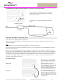
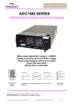
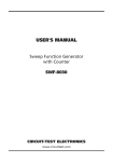
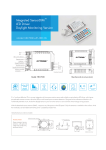
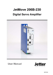
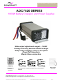
DATASHEET / USER MANUAL ADC7520 SERIES 1600W Battery Chargers and Power Supplies Wide output adjustment range 0…72VDC Analog control by external 0-5VDC voltage Temp.comp charging, sense as on option Power fail relay alarm Master-Slave connection Analog control modular connector Microprocessor controlled charging curves for all kind of batteries Master-Slave connection Sales & R&D Martinkyläntie 43, FI-01720 VANTAA, Tel. +358 10 2890 700 E-mail [email protected], [email protected] Internet www.powernet.fi Powernet reserves the right to change the specification without notice Created: JMa/TRä 08.06.2012/ Updated: 19.08.2015 HLi 752c5l DATASHEET / USER MANUAL POWER SUPPLIES AND BATTERY CHARGERS, TRIMMER ADJUSTABLE Input voltage range Nominal Voltage Nominal Current Max Type **) ADC7520/24 ADC7520/36 ADC7520/48 55-264VAC/78-340VDC 55-264VAC/78-340VDC 55-264VAC/78-340VDC output voltage 24 VDC 36 VDC 48 VDC setting range 0-36 VDC 0-54 VDC 0-72 VDC output current 60 A 40 A 30 A setting range 0-60 A 0-40 A 0-30 A ANALOG CONTROLLABLE MODELS BY EXTERNAL 0-5VDC VOLTAGE Input voltage range Nominal Voltage Nominal Current Type *) **) ADC7520/24AI ADC7520/36AI ADC7520/48AI 55-264VAC/78-340VDC 55-264VAC/78-340VDC 55-264VAC/78-340VDC output voltage 24 VDC 36 VDC 48 VDC setting range 0-36 VDC 0-54 VDC 0-72 VDC output current 60 A 40 A 30 A setting Range 0-60 A 0-40 A 0-30 A power 1600W 1600W 1600W Max power Installation / dimensions (Width x Height x Depth, mm) Wall//Bench 267x135x85 Wall//Bench 267x135x85 Wall//Bench 267x135x85 Installation / dimensions (Width x Height x Depth, mm) 1600W 1600W 1600W Wall//Bench 267x135x85 Wall//Bench 267x135x85 Wall//Bench 267x135x85 BATTERY CHARGERS WITH TEMPERATURE COMPENSATION Type Input voltage range *) ADC7520/24T ADC7520/36T ADC7520/48T **) 55-264VAC/78-340VDC 55-264VAC/78-340VDC 55-264VAC/78-340VDC Output voltage factory setting 27.4 VDC 41.1 VDC 54.8 VDC Programmed output voltages Output current (see table) (see table) 5…36VDC 12…54VDC 24…72VDC 60 A 40 A 30 A Max power Installation / dimensions (Width x Height x Depth, mm) 1600W 1600W 1600W Wall//Bench 267x135x85 Wall//Bench 267x135x85 Wall//Bench 267x135x85 *) Cable sets with modular connectors are included in packing: 1.5m cable set for analog control and 2.5m for or temp.comp models **) Reduced power 55…200VAC or 78…200VDC, see curves at next page MODELS WITH POWER FAIL RELAY ALARM (24V models as a type number example) Type Option description Cable set ADC7520/24H ADC7520/24AIH ADC7520/24TH Trimmer adjustable model with power fail relay alarm Analog controllable model with power fail relay alarm Temp.comp model with Power fail relay alarm 1.5 m, modular connector Analog 1.5m + relay cables 1.5m Temp.comp 2.5m + relay cables 1.5m MASTER-SLAVE CONNECTION (24V models as a type number example) Master units ***) Slave units ADC7520/24 or ADC7520/24AI (optional for ADC7520/24T) ADC7520/24S RS-232 control bus in and out Control to slave via RS-232 bus ADC7520/24SH slave unit with relay, RS-232 bus in only Cable set for master slave connection is included in slave unit type number, length 0.6m modular connectors in both ends ***) Master unit or slave with RS-232 bus output can not include the relay alarm CUSTOMISED VERSIONS ON • • • Cyclic battery chargers or customzed charging curves for all kind of batteries Sense models Customised mechanics Powernet reserves the right to change the specification without notice Created: JMa/TRä 08.06.2012/ Updated: 19.08.2015 HLi 752c5l DATASHEET / USER MANUAL TECHNICAL DATA Input voltage Input current Power factor Efficiency (230VAC, 10…100% load) Inrush current Line regulation Load regulation Output setting accuracy Output ripple (f > 50Hz) Hold up time Status LED indication Standard models Cyclic chargers Isolations Input - chassis Input - output Output - chassis Standards Safety EMC Approvals Protection class Mechanical Electrical Connectors Input Output Dimensions Weight Mounting Cooling Operating temperature range lxwxh Full power typically Reduced power Humidity 55…264 VAC (55…200VAC reduced power, see curve below) 78…340 VDC (78…200VDC reduced power) 9A >0.99 > 88% <30A, cold start 0.01% 0.2V ± 0.1% <30mVrms > 5ms Orange Power OK LED Three color LED, red-yellow-green 1500VAC 3750VAC 500VAC EN60335-2-29 +A2 EN55022B, EN50081-1, EN50082-2 CE marking IP20 metal enclosure Class I Input power cord 10 mm2 2m output cables 267 x 135 x 85 mm with rubber ends 1,9kg without output cables Wall, bench Temperature controlled fan -25ºC...+40ºC +40…+ 70ºC, see curve below 0…95%, non condensing Nominal output voltage / current characteristics 1600W models Output power / input voltage derating curve Powernet reserves the right to change the specification without notice Output power and fan speed vs ambient temperature Created: JMa/TRä 08.06.2012/ Updated: 19.08.2015 HLi 752c5l DATASHEET / USER MANUAL INSTALLATION ← The location must be dry, dust-free indoor use. The acceptable temperature range at full power is -25°C to +40°C. A higher ambient temperature will limit the power, see diagram at first page. The power supply is not waterproof. Keep it dry and away from areas of high humidity to avoid the risk of electrical shock and damage to the charger. ↑ The equipment may be installed either vertically or horizontally. → To ensure sufficient ventilation, leave approximately 10cm free space to both ends of the unit. ↓ The charging process generates explosive hydrogen gas. Keep the area well ventilated. Never use an open flame or equipment that produces sparks near the charger. WALL MOUNTING Screw the power supply to the assembly base by using the mounting brackets on the both ends of the unit. Plug the main power cord into electrical socket. After switching on the mains switch the unit is ready to be used. POWER SUPPLY / CHARGING OPERATION ← Ensure that the unit is switched off and that the environment meets the conditions described previous section ↑ Connect the output cables to the load / battery terminals: + cable to the + terminal and - cable to the - terminal. → Turn the power on by turning the switch to the I position. ↓ During the normal power supply operation / charging process the STATUS light will show a constant orange light. ° To avoid sparking, turn the power off before disconnecting the cables. CONNECTION WITH DC INPUT Wires in PSU’s power cable to be connected as follows: L DC input positive or negative N DC input negative or positive PE Ground OUTPUT VOLTAGE AND CURRENT LIMIT ADJUSTMENT Trimmer or analog control adjustable modules, type example ADC7520/24 or ADC7520/24AI: The output voltage and output current limit of the module can be adjusted as follows: Trimmer adjustable models: with the multi-turn potentiometer located on the front panel Analog controllable models by external 0-5VDC voltage, see detailed instructions Both voltage and current can be adjusted from zero to maximum value. Maximum 800W output power is available within the adjustment range. Temp. comp. models, type example ADC7520/24T: Unit includes 16pcs of programmed output voltages, see temp. comp. models setting tables page. Any of these 16 different voltage settings can be taken in use and additionally this selected voltage can be adjusted ± 5% with the trimmer on front panel. See instructions for choosing the programmed voltage and for the fine tune trimmer adjustment. LED A orange LED indicates that the output of the charger module is healthy. OUTPUT OVERCURRENT PROTECTION Output of the unit is protected against over current and short circuits by automatic, self-resetting electronic current limit. SERIES / PARALLEL CONNECTION Parallel operation: No restrictions, passive load sharing. Series operation: Up to 500V total voltage WARNING! Dangerous voltages, capable of causing death, are present in this equipment. Do not remove the cover. No operator serviceable parts inside. Refer servicing to qualified service personnel. Powernet reserves the right to change the specification without notice Created: JMa/TRä 08.06.2012/ Updated: 19.08.2015 HLi 752c5l DATASHEET / USER MANUAL SELECTION TABLE OF ADC7520 FEATURES This table shows which features are possible at the same time. IF N THEN then not possible. T r i m m er A n a L o g R e l a y B B T u u e s s m p O I ut n S e n s e S w i t c h Some of allowed combinations are optional. Contact manufacturer or your local distributor for further details. Trimmer adjustment Analog control (isolated) Relay alarm BusOut (RS-232 control to slave) BusIn Temp.comp. Sense Customised charging algorithm chargers with code Switch N N N N N N C o d e N N N N N N N N N N N N PIN CONFIGURATION, MODULAR CONNECTORS Front panel Rear panel J1: J3: J5: Analog input 0-5VDC Temperature compensation, Sense option RS-232 bus in and out, master-slave Alternatively power fail relay alarm OPTIONAL ALARM RELAY If the unit is ordered with alarm relay (for example ADC7520/24H), the potential free alarm output indicates if the charger’s output is healthy. The alarm signal is activated at AC fail and charger fail cases. Both normally open and normally closed signals are presented. Pin Configuration, Modular connector J5 with relay alarm option MODULAR JACK Front view CABLE Black = common Red = NO Green = NC RELAY Isolation: Output to Case: 500V Output to GND: 120V Technical data: 1A @ 24Vdc 0,5A @ 120Vac If power is off the COMMON is connected to NC. When power is switched ON the COMMON is connected to NO Powernet reserves the right to change the specification without notice Created: JMa/TRä 08.06.2012/ Updated: 19.08.2015 HLi 752c5l DATASHEET / USER MANUAL OPTIONAL ANALOG CONTROL VERSIONS Analog control option allows full control for output current and voltages and it gives measured values for both of these. There is also available +5V internal power source for logic use. The analog input have 500V electrical insulation to power supply’s input and output. PIN CONFIGURATION, MODULAR CONNECTOR Interface to analog control card is made through AMP Modular 6 connector. It’s part number is 215-876-1. The product specification number is 108-19064 and application number is 114-19019. Part number for cable connector that fits to modular 1 is 737 336-1. Pin configuration of J1: 1. Ground 2. Target value for current 3. Target value for voltage 4. Measured value for current 5. Measured value for voltage 6. +5V, (max 20mA) output Controlling analog card: All control voltages must be between 0 and 5 volts. Over 5V steering is not allowed. Logic for steering is positive so 5V in target value means maximum value from power supply and 0V means minimum output. If controlling connector is unplugged from modular connector, the power supply takes it’s minimum values for output. Measured values can be read from measured signals. Measured voltages are scaled equal as target values. If power supply lies on it’s voltage reference, then measured voltage should be equal as target. Same thing on current steering and it’s measured value. Measured signals (both together) can be loaded only 20mA or proper operation is not guaranteed. Modular connector is isolated from power supply’s input, enclosure and output terminals. That allows serial and parallel connection to separate power supply’s so that equal steering voltages are used. Number or connected devices are not limited. Only be sure that 500V insulation voltage is not exceeded. Connection example, using internal +5VDC power source and external potentiometers: +5V output can be used to feed logic voltages for external circuits. Connection in an example works as a potentiometer controlled power supply. It is important to notice that +5V output is not allowed to load more then 20mA or proper operation is not guaranteed. Tuning instructions: Attention !!! Analog interface is tuned in a factory before it is delivered to customer. There should not be any reason for tuning if card is used between 0-5V voltage values. Qualified person is needed for tuning the device. Tuning can be done with a pair of digital multi meters and example schematic above. Procedure is following: ADC7520 rear panel Location of tuning trimmers for analog control Powernet reserves the right to change the specification without notice 1. Adjust from potentiometers 5V to voltage target and 2V for current target. Connect digital voltage meter to power supply output. Tune from “Voltage Set” trimmer maximum output voltage to right value. 2. Connect digital voltage meter to Modular pin number 5. Tune from trimmer “Voltage Meas” so that digital voltage meter shows always equal value as is in pin 3 (target voltage). 3. Connect digital current meter to output so that it short-circuits the output. Now tune current target potentiometer to 5V. Tune from “Current Set” trimmer output current to value that is maximum value for device according to it’s specification. Be sure that your current meter has a right range. Do never exceed the current values that are specified for the device. If specified value is not known, take a contact to distributor. 4. Measure with digital multi meter voltage from Modular connector pin 4 Tune from trimmer ”Current Meas” to equal with voltage in modular pin 2 (Target Current). Created: JMa/TRä 08.06.2012/ Updated: 19.08.2015 HLi 752c5l DATASHEET / USER MANUAL TEMPERATURE COMPENSATION MODELS, type number example ADC7520/24T The temp.comp cable enables the charger to adjust the output voltage in accordance with battery voltage and temperature fluctuations See instructions for changing and adjusting the output voltage Temp.comp. / sense Modular connector OPTIONAL MASTER SLAVE CONNECTION Using master power supply together with Slave unit. Master unit can be trimmer adjustable standard model ADC7520/24 or analog controllable model ADC7520/24AI (24V as an example). Note ! Unit with relay alarm, type exampleADC7520/24H can’t be used as a master unit. Slave unit is separate unit without any adjustment possibility, type ADC7520/24S or ADC7520/24SH slave with relay alarm (24V as an example). If more current is needed adjustable Master power supply can be parallel or series connected via digital bus to Slave power supply which equals Master but is without adjustment possibility. Then output current or voltage is doubled and the both supplies can still be adjusted thought multi turn potentiometers. Max one slave unit can be used in master-slave connection as a standard. (Please contact your local distributor if more slave units are needed to chain, needs special terminals/wires). Supply’s output terminals and communication bus terminals are isolated so that output's series connection is allowed for more voltage. Bus cable connection: Master unit Slave unit Powernet reserves the right to change the specification without notice Bus cables can be connected from previous units (J5) to the next (J5) with the same way. The first unit must be the master unit (with adjusting knobs). Wrong connection does not damage the units but in that case slaves does not follow the master's commands. Quantity of the slave units is limited to max 1 pcs due to digital bus terminals. In J5 Pins 1 and 3 are serial output pins and pins 2 and 4 are serial input pins. Pin 1 is connected to pin 4 of J5 in the next unit and pin 3 to pin 2 of J5 in the next unit. Created: JMa/TRä 08.06.2012/ Updated: 19.08.2015 HLi 752c5l DATASHEET / USER MANUAL PROGRAMMED VOLTAGES FOR TEMP.COMP. MODELS, type number example ADC7520/24T ADC7520/24T 24VDC 60A Code switch position 0 1 2 3 4 5 6 7 8 9 A B C D E F Nominal Battery voltage 12 VDC 24 VDC 24 VDC 24 VDC Voltage factory setting 5 VDC 12 VDC 13,7 VDC 15 VDC 18 VDC 20 VDC 22 VDC 24 VDC 26 VDC 27,4 VDC 27,4 VDC 27,4 VDC 28 VDC 30 VDC 33 VDC 35 VDC Adjustment range -5% +5% 4,75 VDC 5,25 VDC 11,4 VDC 12,6 VDC 13 VDC 14,4 VDC 14,3 VDC 15,8 VDC 17,1 VDC 18,9 VDC 19 VDC 21 VDC 20,9 VDC 23,1 VDC 22,8 VDC 25,2 VDC 24,7 VDC 27,3 VDC 26 VDC 28,8 VDC 26 VDC 28,8 VDC 26 VDC 28,8 VDC 26,6 VDC 29,4 VDC 28,5 VDC 31,5 VDC 31,4 VDC 34,7 VDC 33,3 VDC 36 VDC Output Current 60 A 60 A 60 A 60 A 60 A 60 A 60 A 60 A 60 A 60 A 40 A 20 A maximum maximum maximum maximum Factory default Voltage factory setting 12 VDC 13,7 VDC 15 VDC 20 VDC 24 VDC 27,4 VDC 30 VDC 33 VDC 36 VDC 38 VDC 41,1 VDC 41,1 VDC 41,1 VDC 45 VDC 48 VDC 52 VDC Adjustment range -5% +5% 11,4 VDC 12,6 VDC 13 VDC 14,4 VDC 14,3 VDC 15,8 VDC 19 VDC 21 VDC 22,8 VDC 25,2 VDC 26 VDC 28,8 VDC 28,5 VDC 31,5 VDC 31,4 VDC 34,7 VDC 34,2 VDC 37,8 VDC 36,1 VDC 39,9 VDC 39 VDC 43,2 VDC 39 VDC 43,2 VDC 39 VDC 43,2 VDC 42,8 VDC 47,3 VDC 45,6 VDC 50,4 VDC 49,4 VDC 54 VDC Output Factory Current default 40 A 40 A 40 A 40 A 40 A 40 A 40 A 40 A 40 A 40 A maximum X 30 A 15 A maximum maximum maximum X ADC7520/36T 36VDC 40A Code switch position 0 1 2 3 4 5 6 7 8 9 A B C D E F Nominal Battery voltage 12 VDC 24 VDC 36 VDC 36 VDC 36 VDC ADC7520/48T 48VDC 30A Code switch position 0 1 2 3 4 5 6 7 8 9 A B C D E F Nominal Battery voltage 24 VDC 36 VDC 48 VDC 48 VDC 48 VDC 60 VDC Voltage factory setting 24 VDC 27,4 VDC 30 VDC 36 VDC 41,1 VDC 45 VDC 48 VDC 52 VDC 54,8 VDC 54,8 VDC 54,8 VDC 57 VDC 60 VDC 65 VDC 68,5 VDC 72 VDC Adjustment range -5% +5% 22,8 VDC 25,2 VDC 26 VDC 28,8 VDC 28,5 VDC 31,5 VDC 34,2 VDC 37,8 VDC 39 VDC 43,2 VDC 42,8 VDC 47,3 VDC 45,6 VDC 50,4 VDC 49,4 VDC 54,6 VDC 52,1 VDC 57,5 VDC 52,1 VDC 57,5 VDC 52,1 VDC 57,5 VDC 54,2 VDC 59,9 VDC 57 VDC 63 VDC 61,8 VDC 68,3 VDC 65,1 VDC 71,9 VDC 68,4 VDC 72 VDC Output Current 30 A 30 A 30 A 30 A 30 A 30 A 30 A 30 A 30 A 20 A 10 A maximum maximum maximum maximum maximum Factory default X Factory default code switch position by bold in tables Powernet reserves the right to change the specification without notice Created: JMa/TRä 08.06.2012/ Updated: 19.08.2015 HLi 752c5l DATASHEET / USER MANUAL INSTRUCTION TO CHANGE THE PROGRAMMED VOLTAGE FOR TEMP.COMP./SENSE MODELS, type number example ADC7520/24T ← Disconnect the power cord from the power line. ↑ Disconnect the output cables from the battery. → See the current code switch position of the unit. ↓ See new switch position code from the programmed output voltages sticker on the unit ° Rotate the code switch to the required position. The hole of the code switch The adjustment can be checked as follows: Short-circuit the output cables of the charger (output short circuit). Connect the charger to the power line. Follow the Status-led color. Switch ON the charger from the on/off switch. Count all the number of green blinks. There must be as much number of blinks as the code switch position number is. Note! If the position of the code switch is O, Status-led blinks only once and returns to red. The code switch positions A…F respond numbers 10…15 ☺ Now the charger has been adjusted! HINTS IF NOT SUCCEED You didn't have chance to count the number of blinks => You can start the test with the on/off switch of the charger again and count. You have made the wrong setting => Switch the charger off again and make the correct setting and count the blinking to check. You cannot find the required charging algorithm on list available => Contact the seller / importer and ask if the charger can be updated with the algorithm you need. Powernet reserves the right to change the specification without notice Created: JMa/TRä 08.06.2012/ Updated: 19.08.2015 HLi 752c5l DATASHEET / USER MANUAL INSTRUCTION TO ADJUST TEMP.COMP/SENSE MODELS VOLTAGE BY THE TRIMMER, type number example ADC7520/24T If the battery is charged in a very cold place or desired constant voltage didn’t found from the charging algorithm list, then there may be need to tune the output voltage. The output voltage can be tuned +/-5% from its nominal value. ← Choose such programmed output voltage, which can reach the desired voltage by +/-5% adjustment. Read the instruction from ”Changing programmed voltage”. ↑ Connect the voltage meter to output wires. → Tune with a small screw driver the voltage calibration trimmer and check the result from volt meter. Clockwise direction increases the voltage. Look at the position below Voltage trimmer When desired voltage is found the tuning is ready. NOTE ! The voltage tuning trimmer affects to every programmed voltage settings. The original list is not valid without returning the original tuning. Incorrect trimmer tuning may be harmful to the battery. Powernet reserves the right to change the specification without notice Created: JMa/TRä 08.06.2012/ Updated: 19.08.2015 HLi 752c5l