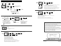
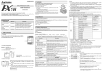
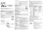
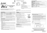
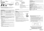
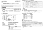
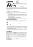
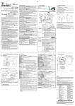
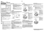
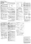
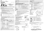
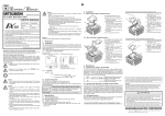
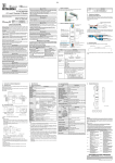
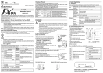
1
Cautions:
2. Installation
1) If a keyword to prohibit read, write or read and write of programs is registered in the PLC, only the
clock time display function is available. Any other function shown above is not available.
If any operation is performed in the 5DM when a keyword is registered in the PLC, the error display
flickers for 5 seconds.
Install the 5DM to the PLC using the following procedure.
A) Top cover for DM (offered as an accessory of 5DM)
B) Connector for optional equipment
C) M3 screw to fix top cover
DISPLAY MODULE FX1N-5DM
USER’S MANUAL
JY992D84901B
This manual only describes the specifications for Display Module FX1N-5DM.
For complete operation, wiring, mounting and programming instructions please refer to the FX1S, FX1N
HARDWARE MANUAL and PROGRAMMING MANUAL.
These manuals should be read and understood before attempting to install or use the unit.
C)
•
Remove the top cover of the basic unit, and attach the top cover for DM
A) instead.
Plug the 5DM in to the connector B).
2) The automatic backlight OFF function is set to 10 minutes as the initial value. As far as the OFF time
is not changed by a sequence program, the backlight turns off 10 minutes later.
If any key is pressed after the backlight turns off, the contents displayed just before the backlight turns
off appear again. A key pressed for the first time after the backlight turns off is regarded as a trigger to
turn on the backlight, and is not regarded as a key operation.
•
If the 5DM is always used, the top cover can be fixed with the M3 screw
C). (Tightening torque: 0.3 to 0.6 Nžm)
4.2 Control devices for 5DM
A)
If the 5DM is used together with a function expansion board, remove and
attach the 5DM by pressing the 5DM mounting hook provided at the bottom
of the 5DM.
B)
When using the 5DM control function, specify data registers (D) and auxiliary relays (M) used to control
the 5DM to special data registers D8158 and D8159.
Five data registers and 15 auxiliary relays are occupied for control of the 5DM.
For the control device use procedure, refer to the FX1S/FX1N/FX2N/FX2NC Series Programming Manual.
Special D
3. Specifications
3.1 Environmental specifications
The environmental specifications are equivalent to those of the PLC main unit. (Refer to the handy manual
offered with the FX1S/FX1N Series PLC main unit.)
Related Manuals
Manual name
Manual No.
FX1S Series Hardware
Manual
FX1N Series Hardware
Manual
FX Series
Programming Manual II
Description
3.2 Power supply specifications
JY992D83901
Describes contents related to hardware of FX1S Series
PLC such as specifications, wiring and installation.
(It is offered with FX1S Series PLC basic unit.)
JY992D88201
Describes contents related to hardware of FX1N Series
PLC such as specifications, wiring and installation.
(It is offered with FX1N Series PLC basic unit.)
JY992D88101
X1
X2
X3
X4
OK
Displays or hides operation errors, etc. *3
Others
M¨+4
ESC key status *4
This section describes the function list of the 5DM.
The operator functions available with the operation keys of the 5DM are described on the back of this manual.
For the 5DM control functions available from the PLC, refer to the FX1S/FX1N/FX2N/FX2NC Series Programming
Manual.
M¨+5
- key status *4
M¨+6
+ key status *4
Function
IN
RUN
ERROR
FX1N-5DM
FX1S-10MR
OUT
0 1 2 3
COM
24+
COM0
Y0
COM1
Y1
COM2
Y2
COM3
Y3
10MR
S: State
T: Timer
C: Counter
Description
Display
Displays current time of clock function (built in FX1S/FX1N Series).
Allows to set time (year, month, day, hour and minute).
Device monitor function
Bit device monitor
Displays ON/OFF status of X, Y, M and S.
Word device (16-bit) monitor
Displays current and set values of T and C and current value of D.
Displays current and set values of 32-bit C and current value of D.
Main unit
: FX1N-5DM
Accessories : Top cover for DM 1
M3 screw to mount top cover 1
Buffer memory monitor function
Displays buffer memory of special units and special blocks
(offered only in FX1N Series).
Error display function
Displays error code and error occurrence step No. when a PLC
error has occurred.
1.3 Outside dimensions
ESC
-
+
OK
➆
Not available.
M¨+12
Not available.
M¨+13
Not available.
M¨+14
Not available.
*2 0: Enables all operations. 1: Enables only the time display function.
2: Enables only the monitor function.
*3 PC hardware errors, parameter errors, grammatical errors and circuit errors are unconditionally displayed.
While this bit is ON, I/O configuration errors, parallel link errors and operation errors are also displayed.
11(0.43)
Data change function
Unit: mm (inches)
Outer painting color: Munsell 0.08GY/7.64/0.81
Mass: 20 g
➃ OK key: Determines the display device, executes write of a numeric value,
or changes over forced setting and forced resetting.
➄ Display area: Displays the current time and the monitored device status.
➅ Connector for PLC
➆ 5DM mounting hook
For specified device
monitor function
*1 Input numeric values correspond to the devices as follows.
1: Input (X) 2: Output (Y) 3: Auxiliary relay (M) 4: State (S) 5: Timer (T)
6: Counter (C), 16-bit (current value/set value) and 32-bit (set value)
7: Data register (D), 16-bit8: Data register (D), 32-bit 9: Time display
10: Counter (C), 16-bit (current value/set value) and 32-bit (current value)
4.3 Description on display area
key: Scrolls the device No. to a larger one or increments a numeric
value.
➅
➀ ➁ ➂ ➃
Not available.
M¨+11
Forces ON and OFF bit devices Y, M and S.
➀ ESC key: Cancels the last key operation or returns to the previous screen.
➁ “-” key: Scrolls the device No. to a smaller one or decrements a numeric
OK
Not available.
M¨+10
Clears current value of T and C (current value: 0, contact: OFF).
➂ “+”
+
M¨+9
T/C reset function
value by.
-
Not available.
Forced set/reset function
1.4 Name of each part
ESC
OK key status *4
M¨+8
17(0.67)
The display area of the 5DM shows the following.
Current value change
Change current value of T, C and D.
Set value change
Change set value of T and C.
5DM control functions: The 5DM is controlled by sequence programs.
For use of these functions, refer to the FX Series Programming Manual ΙΙ
Function
➄
M¨+7
*4 Every operation key is the momentary type, and functions as follows:
While a key is pressed and held: ON
While key is not pressed: OFF
32(1.26)
40(1.57)
D8159
K¨
D: Data register
Setting
Word device (32-bit) monitor
1.2 Product configuration
For protect function
Not available.
M¨+3
Clock function
+
Protects display screen. *2
D¡+4
4. Outline of Performance
POWER
-
D¡+3
For automatic backlight
OFF function
0 1 2 3
ESC
For automatic backlight
OFF function
Disables backlight OFF function.
(Turns on backlight forcedly.)
X5
4 5
Backlight OFF time (min)
M¨+2
Operator functions: The operator can use these functions by using only the operation keys of the 5DM.
Refer to the simplified chart of operations shown on the back face of this manual.
X0
D¡+2
For specified device
monitor function
For specified device
monitor function
1.1 Features
COM
Device No. to be displayed
Requests edition of displayed device data.
Symbols stand for the following.
X: Input Y: Output M: Auxiliary relay
N
D¡+1
Edition completion response
4.1 Function list
L
Application
M¨+1
1. Outline of Product
AC85
- 264V
Description
Device type to be displayed *1
M¨
The power is supplied from the PLC main unit.
5V DC, 110 mA
Describes instructions in FX1S/FX1N/FX2N/FX2NC Series.
The micro display module FX1N-5DM (hereafter referred to as "5DM") is
mounted on the top face of the FX1S/FX1N Series PLC basic unit and
can monitor/update internal PLC data.
D8158
K¡
Control device
D¡
Description
Protect function
Enables full use of all operator functions, enables only monitor
function or enables only clock time display function.
Specified device monitor function
Allows to specify device type and device No. to be displayed in
5DM.
Error display enable/disable
function
Enables or disables error display function (operator function).
Automatic backlight OFF function
Allows to set automatic backlight OFF time (initial value: 10 min).
Operation key status recognition
function
Recognizes ON/OFF status of four operation keys.
➀ ➁
➂ ➃➄
RUN BFM
ON R D
➀ "RUN": Displayed while the PLC is running, and not displayed while
the PLC is stopped.
➅
➆
TCD
XYMS
➁ "BFM": Displays
➇
the contents of the buffer memory when a special
block is connected (only in the FX1N Series).
➈
➂ "ON/OFF": Displayed while T or C is ON in the word device monitor
function, and not displayed while T or C is OFF.
➃ "R" (reset): Displayed while T or C is reset.
➄ "D" (32-bit): Displayed when a 32-bit D is specified.
➅ Device type: Displays the device type (T, C, D, X, Y, M or S) currently
being displayed.
➆ Device No.: Displays the device No. currently being displayed.
➇ Current value: Displays the current value of T, C or D.
➈ Set value: Displays the set value of T or C.
* In the case of 32-bit C or D, upper 5 digits are displayed in ➇ and the
lower 5 digits are displayed in ➈.
5. Operation List
<Monitoring 32-bit C>
Current value
The process for the operator functions are shown below.
•
RUN
1
The operation keys are expressed as follows.
ESC : ESC key
-
: - key
+
: + key
OK
OK
OK
Determine
the input.
➃
Press and hold it for
2 seconds or more.
➄
➂
➀
+
➀ Press the + or - key to change over the current value and the set value. For the set value,
-
"S" is added in a right position above the device No.
+
OK
+1
Determine
the input.
-
➀ An item being changed flickers.
➁ Set "year, month, day, hour and
RUN
➁ When the OK key is pressed, the current value or the set value is changed.
D
C
S
time" in this order.
➁
➂ Press the + key to increase the value. Press the - key to decrease the value.
➃ Press the OK key to determine the input. At this time, the input data is written to the PLC.
-1
<Selecting a device>
OK
<Resetting the current value>
OK
+
➁
-
<Setting the time>
Press and hold
it for 2 seconds
or more. ➀
D
C
OK : OK key
Time display screen (when the power is turned on)
RUN
<Changing the current set value of
32-bit C>
Set value
➂
+
TCD
XYMS
-
OK
To
changed, the current value is reset to "0" and the contact turns off.
Determine
the input.
<Monitoring 16- or 32-bit D>
➀
➂ Select an either device using the + and - keys.
key
<Changing the current value of 16- or 32-bit D>
RUN
(In the initial status, "D" flickers.)
T, C, D (16-bit), D (32-bit), X, Y, M, S or BFM
-
➄ When the OK key is pressed and held for 2 seconds or more while the current value is
1
1
+
D
OK
OK
+
➂
➄
+ key
* "BFM" is displayed only when the FX1N Series
PLC is used.
-
-
➁
➃
➀ For a 32-bit D, "D" is displayed.
➁ For 16-bit D, D is scrolled by 1 point at a time.
For 32-bit D, D is scrolled by 2 points at a time by the + key and by 1 point at a time by the - key.
<Monitoring a bit device (X/Y/M/S)>
➂ Select the current value change mode.
<Forced setting/resetting a bit device (Y/M/S)>
RUN
➃ Press the + key to increase the value. Press the - key to decrease the value.
RUN
1
+
OK
➂
Y
➀
+
OK
Y
Set or reset the bit
device.
-
-
➁
➃
➀ From the displayed device No., the ON/OFF
status of 8 points (in the case of X or Y) or 10
points (in the case of M or S) is indicated.
: OFF status
: ON status
➂
➂ Forced set/reset mode
A selected device is indicated with underline.
OK
➄ Press the OK key to determine the input. At this time, the input data is written to the PLC.
➄
➃ Select a device No.
➄ The current ON/OFF status is reversed.
Underline flickers.
➁ Eight points (in the case of X or Y) or 10 points
(in the case of M or S) are scrolled at a time.
+ key: Scrolls toward larger device Nos.
- key: Scrolls toward smaller device Nos.
* The device turns on and off alternately
when the OK key is pressed.
If the OK key is pressed while the
device is ON, it turns off.
If the OK key is pressed while the
device is OFF, it turns on.
Guidelines for the safety of the user and protection of the Micro Display Module
FX1N-5DM
•
This manual has been written to be used by trained and competent personnel. This is defined
by the European directives for machinery, low voltage and EMC.
•
If in doubt at any stage during the installation of the Micro Display Module FX1N-5DM always
consult a professional electrical engineer who is qualified and trained to the local and national
standards. If in doubt about the operation or use of the Micro Display Module FX1N-5DM
please consult the nearest Mitsubishi Electric distributor.
•
Under no circumstances will Mitsubishi Electric be liable or responsible for any consequential
damage that may arise as a result of the installation or use of this equipment.
•
All examples and diagrams shown in this manual are intended only as an aid to understanding
the text, not to guarantee operation. Mitsubishi Electric will accept no responsibility for actual
use of the product based on these illustrative examples.
•
Owing to the very great variety in possible application of this equipment, you must satisfy
yourself as to its suitability for your specific application.
<Error display>
➀ Error step No.
➁ Error code
Press the ESC key or release the error status to
delete the error display.
➀
➁
<Monitoring 16-bit T/C>
➀
<Changing the current set value of 16- <Resetting the current value>
bit T/C>
RUN
1
T
+
OK
+
-
➁
➂
OK OK OK
Changing the
current value
OK
Determine
the input.
Change the
current value.
-
➄
OK
Press and hold it for
2 seconds or more.
➅
Manual number : JY992D84901
➃
Manual revision : B
➀ If T or C is ON, "ON" is displayed. If T or C is reset, "R" is displayed.
Date
➁ Change over the device to be monitored.
: MAY 2000
T and C not used in the program are not displayed.
(If no T or C is used in the program, "-" is displayed.)
➂ Press the OK key once to change the current value.
Press the OK key three times to change the set value.
(While the current value or set value is changed, it flickers.)
HEAD OFFICE : MITSUBISHI DENKI BLDG MARUNOUTI TOKYO 100-8310
HIMEJI WORKS : 840, CHIYODA CHO, HIMEJI, JAPAN
➃ Press the + key to increase the value. Press the - key to decrease the value.
➄ Press the OK key to determine the input. At this time, the input data is written to the PLC.
➅ When the OK key is pressed and held for 2 seconds or more while the current value is
changed, the current value is reset to "0" and the contact turns off.
JY992D84901B
TELEX : J24532 CABLE MELCO TOKYO
Effective MAY 2000
Specifications are subject to
change without notice