1
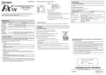
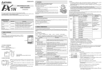
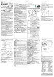
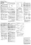
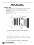
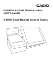
JY992D81801A
1.2 RS232C Connector Pin Layout (D-SUB 25 Pin)
Date: 1999 September
13 12 11 10 9 8 7 6 5 4 3 2 1
This manual contains text, diagrams and explanations which will guide the reader in the correct installation and operation
of the FX-485PC-IF RS485 Interface Unit. It should be read and understood before attempting to install or use the unit.
Further information can be found in the FX Communication User’s manual.
If in doubt at any stage during the installation of the FX-485PC-IF Interface Unit always consult a professional electrical
engineer who is qualified and trained to the local and national standards.
25 24 23 22 21 20 19 18 17 16 15 14
FX-485PC-IF RS485 Interface Unit Hardware Manual
Pin No.
1. Introduction
F X ,F X 0N ,F X 2N ,F X 2N C ,A
series pro gram m able
controller(s) *1
485P C -IF
*1 Each programmable controller requires
necessary adaptor or unit for suporting
computer link.
For system configuration of computer link,
refer to FX communication user’s manual.
For A series, refer to A series manual.
Dimensions: mm (inches)
b)
2
SD (TXD)
Send data (485PC-IF → RS232C device(computer))
3
RD (RXD)
Receive data (RS232C device(computer) → 485PC-IF)
4
RS (RTS)
5
CS (CTS)
No used (These pins are connected inside 485PC-IF. In some cases computer
may require connection.)
6
DR (DSR)
No used (This pin is connected to ER (DTR) inside 485PC-IF. In some cases computer may require connection.)
7
SG
Signal ground
8 to 19
NC
No connection
ER (DTR)
No used (This pin is connected to DR (DSR) inside 485PC-IF. In some cases
computer may require connection.)
NC
No connection
20
No connection
Caution for wiring
•
The terminal screws for the terminal block of the RS485 are M3 screws and therefore the crimp style terminal (see
drawing) suitable for use with these screws should be fitted to the cable for wiring.
6.2 m m (0.2 4" )
or less
•
a)
NC
2. Wiring
C om puter
1.1 External Dimensions
Description
1
21 to 25
The interface unit FX-485PC-IF (hereinafter referred to as “485PC-IF”) can exchange signal of RS232C and RS485
(RS422) for computer link.
Signal Name
F or M 3 (0.1 2")
F or M 3 (0.1 2")
D im ensions : m m (inches)
6.2 m m (0.2 4")
or less
The terminal tightening torque is 0.5 to 0.8 Nm (5 to 8 kgf.cm), and tighten securely to avoid malfunction.
2.1 Connecting to a Computer (RS232C)
Weight: Approx. 0.3kg (0.66lbs)
c)
d)
e)
Accessories: Terminating resistor (330Ω × 2, 110Ω × 1)
f)
M IT S U B IS H I
POW ER
RS-232C
5 V DC
RD
80 (3.15")
SD
F X-485P C -IF
R S -4 2 2 /4 8 5
SDA SDB RDA RDB
485P C -IF
S ignal N am e P in N o.
S D (T X D )
2
R D (R X D )
3
R S (R T S )
4
C S (C T S )
5
D R (D S R )
6
SG
7
E R (D T R )
20
C om puter
S ignal N am e
S D (T X D )
R D (R X D )
R S (R T S )
C S (C T S )
D R (D S R )
SG
E R (D T R )
LINK SG
Note
100 (3.94")
h)
a)
b)
c)
d)
e)
f)
g)
RS (RTS) and CS (CTS), DR(DSR) and ER (DTR) signals are not used, but are connected inside the 485PC-IF, connect wiring depending on the need of the computer.
30
(1.18")
2.2 Connecting to a Programmable Controller(s) (RS485/RS422)
RS232C connector:
RD LED:
SD LED:
POWER LED:
Power supply cable grip:
Power feed jack:
Used for connection between 485PC-IF and computer.
Lit when the programmable controller sends data to the computer.
Lit when the programmable controller receives data from the computer.
Lit when 5V is supplied to the power feed jack f).
Safety grip to prevent disconnection of 5 V power supply.
Jack for connecting power supply unit.
For using a plug with specifications, refer to section 3.2.
g) Terminal cover mounting screws (M3 (0.12"))
h) Terminal for RS422/485:
Used in connection 485PC-IF and programmable controller(s).
Terminal
Description
SDA
This terminal is used when the programmable controller receives data
from the computer.
SDB
RDA
RDB
LINK SG
This terminal is used when the programmable controller sends data to
the computer.
Signal ground
2.2.1 Selection of Wiring
Wiring of RS485 is one-pair wiring or two-pair wiring. The wiring method is decided according to the usage. Please select the wiring method from the table below. For message wait and on-demand function, please see FX Communication User’s Manual.
Using Computer Link
If is necessary to set the message wait to 70ms or less
If is not necessary to set the message wait to 70ms or less
×
*
1
×
Use on-demand function
........ Recommendation, ......... OK,
One-pair wiring
(Refer to section2.2.3)
Two-pair wiring
(Refer to section2.2.2)
× .......... Can not use
*1 When using 485PC-IF with this wiring method remember to take account for/or ignore the “echo” of the commands sent from
computer.
3.2 Power Supply Specifications
2.2.2 Two-pair Wiring
485P C -IF
R *1
F X 2N -485-B D
A series pro gram m able
controllers' c om puter link unit
F X (0N ) -485A D P
SDA
SDA
SDA
SDA
SDB
SDB
SDB
SDB
RDA
RDA
RD
A
RDA
RDB
RDB
RD
B
RDB
R *1
Items
Description
Power source
5 V DC ± 5%
Current consumption
Max. 260 mA
Note
SG
LIN K S G
*2
R *1
SG
*3
FG
Transmission standard
Description
RS232C
Conforming to RS232C
RS485/422
Conforming to RS485 and RS232C
Communication method
G rounding of resistance 100Ω or less
*1 R is the terminating resistor. Connect the terminating resistor (330Ω) between terminals SDA and SDB, and terminals RDA
and RDB.
*2 The shield of the shielded twisted-pair cable must be connected to ground (100Ω or less). When using parallel link, ground
both side. When using no protocol or dedicated protocol, ground one side.
*3 Connect terminal FG to each terminal of the programmable controller main body grounded with resistance of 100 Ω or less.
However, for the computer link unit of the A series programmable controller, see the manual of the computer link unit.
2.2.3 One-pair Wiring
485P C -IF
SDA
F X (0N ) -485A D P
SDA
SDA
SDB
SDB
R *1
F X 2N -485-B D
A series pro gram m able
controllers c om puter link unit
SDB
RDA
RDA
RDB
RDB
RDB
RDB
*2
RS232C
Max. 15 m
RS485/422
Max. 500 m
Supported baud rate
300 to 19,200 bps
Isolation
Photo coupler isolation and transformer isolation
(between programmable controller and communication signal)
4. Diagnostics
For diagnostics of computer link, please see FX Communication User’s Manual.
4.1 POWER LED Check
R *1
Description
Lit
Power source is OK.
Otherwise
Check power supply unit and connection.
4.2 SD LED and RD LED Check
Check the status of the SD LED and the RD LED.
Location
LIN K
SG
*3
FG
SG
*3
FG
*1 R is the terminating resistor. Connect the terminating resistor (110Ω) between terminals RDA and RDB.
*2 The shield of the shielded twisted-pair cable must be connected to ground (100Ω or less).
*3 Connect terminal FG to each terminal of the programmable controller main body grounded with resistance of 100Ω or less.
However, for the computer link unit of the A series programmable controller, see the manual of the computer link unit.
Sending data form programmable controller to computer.
500 V AC > 1 min, tested between terminals in batch and case
5 MΩ > 500 V DC, tested between terminals in batch and case
Wiring between computer and 485PC-IF is OK.
SD LED is not lit
Check wiring between computer and 485PC-IF. Check that data has been
sent from computer.
RD LED is lit
Wiring between programmable controller and 485PC-IF is OK.
RD LED is not lit
Check wiring between programmable controller and 485PC-IF. Check setting of programmable controller(s) for computer link.
This manual has been written to be used by trained and competent personnel. This is defined by the European directives for
machinery, low voltage and EMC.
•
If in doubt at any stage during the installation of the FX-485PC-IF always consult a professional electrical engineer who is qualified
and trained to the local and national standards. If in doubt about the operation or use of the FX-485PC-IF please consult the nearest Mitsubishi Electric distributor.
•
Under no circumstances will Mitsubishi Electric be liable or responsible for any consequential damage that may arise as a result of
the installation or use of this equipment.
•
All examples and diagrams shown in this manual are intended only as an aid to understanding the text, not to guarantee operation. Mitsubishi Electric will accept no responsibility for actual use of the product based on these illustrative examples.
•
Owing to the very great variety in possible application of this equipment, you must satisfy yourself as to its suitability for your specific application.
General specifications other than the those-mentioned below are the same as for the FX or FX2N series programmable controller.
Insulation Resistance
SD LED is lit
•
3.1 General Specifications
Dielectric withstand voltage
Check Point
Guidelines for the safety of the user and protection of the FX-485PC-IF RS485 Interface Unit
3. Specifications
Description
LED Status
Sending data form computer to
programmable controller(s).
G rounding of resistance 100Ω or less
Items
Full-duplex communication
LED Status
SDB
RDA
SG
transmission
distance
SDA
RDA
LIN K S G
D im ensions: m m (inches)
3.3 Performance Specifications
Items
LIN K
SG
*3
FG
φ5.5(0.22")
φ2.1(0.08")
9.5 (0.37")
R *1
Use a plug with specifications as shown right.
HEAD OFFICE : MITSUBISHI DENKI BLDG MARUNOUTI TOKYO 100-8310
HIMEJI WORKS : 840, CHIYODA CHO, HIMEJI, JAPAN
TELEX : J24532 CABLE MELCO TOKYO
Specifications are subject to change without notice