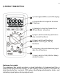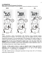
1
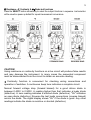
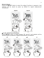
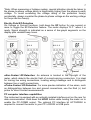
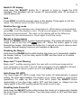
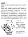
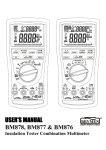
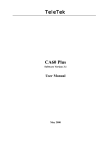
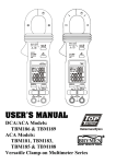
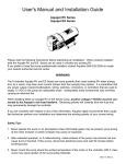
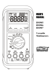
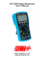
ACT 6000 Digital Multimeter User`s Manual www.actmeters.co.uk www.actmeters.com 1 1) SAFETY Terms in this manual WARNING identifies conditions and actions that could result in serious injury or even death to the user. CAUTION identifies conditions and actions that could cause damage or malfunction in the instrument. This manual contains information and warnings that must be followed for operating the instrument safely and maintaining the instrument in a safe operating condition. If the instrument is used in a manner not specified by the manufacturer, the protection provided by the instrument may be impaired. The meter is intended only for indoor use. The meter protection rating, against the users, is double insulation per IEC/UL/EN61010-1 Ed. 3.0, IEC/EN61010-2-030 Ed. 1.0, IEC/EN61010-2-033 Ed. 1.0, IEC/UL/EN61010-031 Ed. 1.1 and CAN/CSA-C22.2 No. 61010-1-12 Ed. 3.0 to CAT II 1000V, CAT III 600V and CAT IV 300V AC & DC. Terminals (to COM) measurement category: V / mAA / A :CAT II 1000V, CAT III 600V and CAT IV 300V AC & DC. Per IEC61010-1 2nd Ed. (2001) Measurement Category Measurement Category IV (CAT IV) is for measurements performed at the source of the low-voltage installation. Examples are electricity meters and measurements on primary overcurrent protection devices and ripple control units. Measurement Category III (CAT III) is for measurements performed in the building installation. Examples are measurements on distribution boards, circuitbreakers, wiring, including cables, bus-bars, junction boxes, switches, socketoutlets in the fixed installation, and equipment for industrial use and some other equipment, for example, stationary motors with permanent connection to the fixed installation. Measurement Category II (CAT II) is for measurements performed on circuits directly connected to the low voltage installation. Examples are measurements on household appliances, portable tools and similar equipment. ACT Meters Ltd strongly recommends studying and adhering to the Heath & Safety Executive (HSE) Guidance Note GS38 before using this or any other test equipment on live mains. For your own safety it is essential to use adequately fused test leads, such as the ACT/418F, when working on an unfused incoming mains supply (eg. Consumer Unit / Tails). 2 WARNING To reduce the risk of fire or electric shock, do not expose this product to rain or moisture. To avoid electrical shock hazard, observe the proper safety precautions when working with voltages above 60 VDC or 30 VAC rms. These voltage levels pose a potential shock hazard to the user. Do not touch test lead tips or the circuit being tested while power is applied to the circuit being measured. Keep your fingers behind the finger guards of the test leads during measurement. Inspect test leads, connectors, and probes for damaged insulation or exposed metal before using the instrument. If any defects are found, replace them immediately. Do not measure any current that exceeds the current rating of the protection fuse. Do not attempt a current measurement to any circuit where the open circuit voltage is above the protection fuse voltage rating. Suspected open circuit voltage should be checked with voltage functions. Never attempt a voltage measurement with the test lead inserted into the A/mA or A input jack. Only replace a blown fuse with one of the proper rating as specified in this manual. Using fuses differing to those specified immediately voids the warranty and could impair the performance and protection offered by the instrument. Only use the test leads provided with the equipment or Probe Assembly rated CAT III 1000V or better. CAUTION Disconnect the test leads from the test points before changing functions. Always set the instrument to the highest range and work downwards for an unknown value when using manual ranging mode. INTERNATIONAL ELECTRICAL SYMBOLS ! Caution ! Refer to the explanation in this Manual Caution ! Risk of electric shock Earth (Ground) Double Insulation or Reinforced insulation Fuse AC--Alternating Current DC--Direct Current CENELEC DIRECTIVES The instrument conforms to CENELEC Low-voltage directive 2006/95/EC and Electromagnetic compatibility directive 2004/108/EC 3 2) PRODUCT DESCRIPTION 1) 3-5/6 digits 6000 count LCD display 2) Push-buttons for special functions & features 3) Selector to turn the Power On or Off and Select a function 4) Input Jack for milli-amp and microamp current functions 5) Input Jack for all functions EXCEPT current (A, mA, A) functions 6) Common (Ground reference) Input Jack for all functions 7) Input Jack for 10A (20A for 30sec) current function Analogue bar-graph The analogue bar graph provides a visual indication of measurement like a traditional analogue meter needle. Its fast update speed (40/sec) is excellent at detecting faulty door contacts, PIR relays, identifying potentiometer clicks, and indicating signal spikes during adjustments. 4 3) OPERATION DCV, ACV & Line Frequency functions Hold down the Hz button for one second or more to activate or to exit Hz. Note: *Input sensitivity varies automatically with function range selected before activating the Hz function. 6V function range has the highest and the 1000V range has the lowest. It is recommended to first measure the signal voltage (or current) level then activate the Hz function in that voltage (or current) range to automatically set the most appropriate trigger level. You can also press the RANGE button momentarily to select another trigger level manually. If the Hz reading becomes unstable, select lower sensitivity to avoid electrical noise. If the reading shows zero, select higher sensitivity. *Number of Bar-graph pointer is used to indicate input range (sensitivity) selected. 1/2/3/4 pointers indicate 6/60/600/1000V, 6/10/-/-A, 60/600/-/-mA or 600/6000/-/-uA is selected in corresponding V, A, mA or uA function respectively. ( “-” means range not available) *The Hz of mV function is designed specially for logic level (3V or 5V family) frequency measurement. 5 Resistance, Continuity & Diode test functions Press the SELECT button momentarily to select the subject functions in sequence. Last selection will be saved as power up default for repeat measurement convenience. CAUTION Using resistance or continuity functions on a live circuit will produce false results and may damage the instrument. In many cases the suspected component must be disconnected from the circuit to obtain an accurate reading. Continuity function is convenient for checking wiring connections and operation of switches. A continuous beep tone indicates a complete circuit. Normal forward voltage drop (forward biased) for a good silicon diode is between 0.400V to 0.900V. A reading higher than that indicates a leaky diode (defective). A zero reading indicates a shorted diode (defective). "OL" indicates an open diode (defective). Reverse the test leads connections (reverse biased) across the diode. The digital display shows "OL" if the diode is good. Any other readings indicate the diode is resistive or shorted (defective). 6 DCmV & ACmV Press the SELECT button to select the subject functions in sequence. Last selection will be saved as power up default for repeat measurement convenience. A, mA, and A Current functions Press SELECT button to toggle between DC and AC. Last selection will be saved as power up default for repeat measurement convenience. 7 *Note: When measuring a 3-phase system, special attention should be taken to the phase-to-phase voltage which is significantly higher than the phase-to-earth voltage. To avoid exceeding the voltage rating of the protection fuse(s) accidentally, always consider the phase-to-phase voltage as the working voltage for the protection fuse(s). Electric Field EF-Detection On Voltage or Current functions, hold down the EF button for one second or more to toggle the EF-Detection feature. The meter displays “E.F.” when it is ready. Signal strength is indicated as a series of bar-graph segments on the display plus variable beep tones. ●Non-Contact EF-Detection: An antenna is located in the top-right of the meter, which detects the electric field of current-carrying conductors. It is ideal for tracing live wiring connections, locating wiring breakage and to distinguish between live or earth connections. ●Probe-Contact EF-Detection: For more precise indication of live wires, such as distinguishing between live and ground connections, use the Red (+) test probe for direct contact measurements. PC computer interface capabilities The instrument is equiped with an optically isolated interface port on the rear for data communication. Hold down the HOLD button while turning the meter on to enable the PC-COMM output. The optional PC interface kit ACT/6000IK is required to connect the meter to your PC`s RS232 or USB ports. 8 Backlit LCD display Hold down the SELECT button for 1 second or more to toggle the LCD backlight. The backlight will be turned off automatically after 32 seconds to extend battery life. Hold Press HOLD to hold the present value on the display. Press again to exit this mode. This feature does not affect the bar graph. Relative Zero ( ) mode Finds the difference between two measurements. While taking a measurement, press REL to set the display to zero. The Δ icon will appear on the display. Take the second measurement. The value on the display will be the difference between the two measurements. Press again to exit this mode. Manual or Auto-ranging Press the RANGE button to select manual-ranging. The meter will remain in the range it was in but the LCD turns off. Press the button again to step through the ranges. Hold down the button for 1 second or more to resume autoranging. Manual ranging feature is not available in Hz mode. Disabling the Beeper Hold down the RANGE button while turning the meter on to temporarily disable the beeper feature. Turn the rotary switch to OFF and then back on to enable the beeper again. Beep-Jack™ Input Warning Beep-Jack™ audible warning alerts the user with a continuous beep and an error message on the LCD if the test lead is plugged into the mA/μA or A input terminal while the selector switch is not in the mA/μA or A position. Auto-Power-Off (APO) The Auto-Power-Off (APO) mode turns the meter off automatically to extend battery life after approximately 34 minutes of no rotary switch or push button operations. To wake up the meter from APO, press the SELECT button momentarily or turn the rotary switch OFF and then back on. Always turn the rotary switch to the OFF position when the meter is not in use. Disabling Auto-Power-Off Hold down the SELECT button while turning the meter on to temporarily disable the Auto-Power-Off (APO) feature. Turn the rotary switch to OFF and then back on to resume. 9 4) MAINTENANCE WARNING To avoid electrical shock, disconnect the meter from any circuit, remove the test leads from the input jacks and turn OFF the meter before opening the battery cover. Do not operate with the case open. Install only the same type of fuse or equivalent. Calibration Periodic calibration at intervals of one year is recommended to maintain meter accuracy. Accuracy is specified for a period of one year after calibration. If selfdiagnostic message “C_Er” is being displayed while powering on, some meter ranges might be out of specification. To avoid misleading measurements, stop using the meter and send it for re-calibration. Refer to the LIMITED WARRANTY section for obtaining warranty or repair service. Trouble Shooting If the instrument fails to operate, check battery, fuses, leads, etc., and replace as necessary. Double check operating procedure as described in this user’s manual. If the instrument voltage-resistance input terminal is subjected to a high voltage transient (caused by lightning or switching surge to the system) by accident or abnormal conditions of operation, the series fusible resistors will blow (become high impedance) like fuses to protect the user and the instrument. Most measuring functions through this terminal will then be open circuit. The series fusible resistors and the spark gaps should only be replaced by ACT Meters Ltd. Refer to the LIMITED WARRANTY section for obtaining warranty or repair service, or call +44 (0) 1744 88 6660. Battery and Fuse replacement: Battery: 1.5V AAA Size alkaline battery (x2) Fuses: Fuse (F1) for A/mA current input: 0.4A/1000V AC & DC, IR 30kA, F fuse; Dimension: 6 x 32 mm Fuse (F2) for A current input: 11A/1000V AC & DC, IR 20kA, F fuse; Dimension: 10 x 38mm Loosen the screw from the access cover of the case bottom. Lift off the access cover. Replace the batteries or fuse(s). Replace access cover and fasten the screw. 10 5) GENERAL SPECIFICATION Display: 3-5/6 digits 6,000 count Update Rate: 5 per second nominal 24 Segments Bar graph: 40 per second max Operating Temperature: 0oC to 40oC Relative Humidity: Maximum relative humidity 80% for temperature up to 31oC decreasing linearly to 50% relative humidity at 40oC Altitude: Operating below 2000m Storage Temperature: -20oC ~ 60oC, < 80% R.H. (with batteries removed) Temperature Coefficient: Nominal 0.15 x (specified accuracy)/ oC @ (0oC ~ 18oC or 28oC ~ 40oC), or otherwise specified Sensing: Average sensing Pollution Degree: 2 Safety: per IEC/UL/EN61010-1 Ed. 3.0, IEC/EN61010-2-030 Ed. 1.0, IEC/EN61010-2-033 Ed. 1.0, IEC/UL/EN61010-031 Ed. 1.1 and CAN/CSAC22.2 No. 61010-1-12 Ed. 3.0 to CAT II 1000V, CAT III 600V and CAT IV 300V AC & DC Transient Protection: 6.5kV (1.2/50s surge) Terminals (to COM) Measurement Category: A, mA/A & V: CAT II 1000V, CAT III 600V and CAT IV 300V AC & DC E.M.C. : Meets EN61326-1:2006 (EN55022, EN61000-3-2, EN61000-3-3, EN61000-4-2, EN61000-4-3, EN61000-4-4, , EN61000-4-5, EN61000-4-6, EN61000-4-8, EN61000-4-11) In an RF field of 3V/m: Other function ranges: Total Accuracy = Specified Accuracy + 100 digits Performance above 3V/m is not specified Overload Protection: A & mA: 0.4A/1000V DC/AC rms, IR 30kA @ 1000V DC/AC rms A: 11A/1000V DC/AC rms, IR 20kA @ 1000V DC/AC rms V: 1100V DC/AC rms mV, Ohm & others: 1000V DC/AC rms Low Battery: Below approx. 2.3V Power Supply: 1.5V AAA Size battery X 2 Power Consumption (typical): 3.5mA APO Consumption (typical): 10A APO Timing: Idle for 34 minutes Dimension: 161*81*50mm L*W*H (With Holster) Weight: Approx. 340 gm (With Holster) Special Features: Backlit LCD; Auto-ranging; Relative Zero mode; Display Hold; EF-Detection (NCV); Interface capabilities with PC computer; Input warning detection Included Accessories: Gold-plated (tips) silicon test lead set; Rubber Holster; Magnetic Hanger; 2 x AAA batteries (installed); user’s manual Optional Accessories: ACT/6000IK PC Interface Kit, ACT/430N Padded Case, 11 ACT/CA60 Current Clamp 6) ELECTRICAL SPECIFICATION Accuracy is given as +/- (% of reading digits + number of digits) or otherwise specified @ 23oC +/- 5oC and less than 75% R.H. AC Voltage RANGE Accuracy 50Hz ~ 400Hz 60.00mV, 600.0mV 1.0% + 5d 6.000V, 60.00V, 600.0V, 1000V CMRR: >60dB @ DC to 60Hz, Rs=1k Input Impedance: 10M, 50 pF nominal Ohm RANGE Accuracy 600.0, 6.000K, 0.5%+4d 60.00K, 600.0K 6.000M 0.7%+4d 60.00M 1.2%+4d Open Circuit Voltage: 0.45VDC typical DC Voltage RANGE Accuracy 60.00mV 0.4%+5d 600.0mV 0.2%+3d 6.000V, 60.00V, 600.0V, 1000V NMRR: > 60dB @ 50Hz/60Hz CMRR: > 100dB @ DC, 50Hz/60Hz; Rs=1k Input Impedance: 10M, 50 pF nominal Audible Continuity Tester Audible Threshold: Below 20 typically Response time: 32ms Diode Tester RANGE Accuracy 1.000V 1.0% + 3d Test Current: 0.56mA typically Open Circuit Voltage: < 1.8VDC typically DC Current Accura Burden cy Voltage 0.5%+5 600.0A d 0.10 mV/uA 0.5%+3 6000A d 0.5%+5 60.00mA d 1.7 mV/mA 0.5%+3 600.0mA d 1.2%+6 6.000A d 0.03V/A 1.8%+6 1) 10.00A d 1) 10A continuous, >10A to 20A for 30 sec. max with 5 minutes cool down interval RANGE AC Current RANGE 50HZ ~ 400HZ 600.0A, 6000A 60.00mA, 600.0mA Accura cy 1.0%+3 d Burden Voltage 0.10 mV/uA 1.7 mV/mA 1.2%+6 d 0.03V/A 1.8%+6 1) 10.00A d 1) 10A continuous, >10A to 20A for 30 sec. max with 5 minutes cool down interval 6.000A 12 Logic Level Hz (mV Function) Sensitivity RANGE (square wave) 5.00 Hz ~ 500.0 kHz 3 Vpeak 5.00 Hz ~ 1.000 MHz 5 Vpeak Accuracy: 0.03%+2d Hz (Line) @ ACV, DCV, Current Sensitivity Function Range (Sine RMS) 6V 0.4V 10Hz - 10kHz 60V 4V 10Hz - 50kHz 600V 40V 10Hz - 50kHz 1000V 400V 45Hz - 1kHz 600A 40A 10Hz - 10kHz 6000A 400A 10Hz - 10kHz 60mA 4mA 10Hz - 10kHz 600mA 40mA 10Hz - 10kHz 6A 1A 10Hz - 1kHz 10A 6A 10Hz - 1kHz Accuracy: 0.03%+3d Non-Contact EF-Detection Typical Voltage BarGraph Indication 20V (tolerance: 10V ~ 36V) 55V (tolerance: 23V ~ -83V) 110V (tolerance: 59V ~ --165V) 220V (tolerance:124V ~ ---330V) 440V (tolerance:250V & ----1000V) Indication: Bar-graph segments & audible beep tones proportional to the field strength Detection Frequency: 50/60Hz Detection Antenna: Top-right Corner Probe-Contact EF-Detection: For more precise indication of live wires, such as distinguishing between live and ground connections, use the Red (+) test probe for direct contact measurement All specifications are nominal and may change as design improvements occur. ACT Meters Ltd shall not be liable for damages resulting from misapplication or misuse of its products. E&OE. 13 LIMITED WARRANTY ACT Meters Ltd warrants to the original product purchaser that each product it manufactures will be free from defects in material and workmanship under normal use and service within a period of 12 months from the date of purchase. This warranty does not apply to accessories, fuses, fusible resistors, spark gaps, batteries or any product which, in ACT Meter`s opinion, has been misused, altered, neglected, or damaged by accident or abnormal conditions of operation or handling. To obtain warranty service, contact ACT Meters Ltd or its authorized agent and send the product, with proof of purchase and description of the difficulty, postage and insurance prepaid, to the address given. ACT Meters Ltd assumes no risk for damage in transit. ACT Meters Ltd will, at its option, repair or replace the defective product free of charge. However, if ACT Meters Ltd determines that the failure was caused by misuse, altered, neglected, or damaged by accident or abnormal conditions of operation or handling, you will be billed for the repair. Use of non-original accessories, unauthorized opening, attempted repair, or the fitting of incorrect value fuses, invalidates the warranty. THIS WARRANTY IS EXCLUSIVE AND IS IN LIEU OF ALL OTHER WARRANTIES, EXPRESSED OR IMPLIED, INCLUDING BUT NOT LIMITED TO ANY IMPLIED WARRANTY OR MERCHANTABILITY OR FITNESS FOR A PARTICULAR PURPOSE OR USE. ACT METERS LTD WILL NOT BE LIABLE FOR ANY SPECIAL, INDIRECT, INCIDENTAL OR CONSEQUENTIAL DAMAGES. STATEMENT OF CONFORMITY ACT Meters Ltd is certified in accordance with ISO 9001 for our Quality Management Systems. The instrument enclosed has been checked and/or calibrated using equipment that is traceable to National Standards. Do not discard of this product in household waste! It contains valuable materials. For recycling information visit actmeters.co.uk Mark on your equipment certifies that this equipment meets the requirements of the EC (European Community) regulations concerning safety and electromagnetic compatibility. 14 ACT Meters Ltd strongly recommends studying and adhering to the Heath & Safety Executive (HSE) Guidance Note GS38 before using this or any other test equipment on live mains. For your own safety it is essential to use adequately fused test leads, such as the ACT/418F, when working on an unfused incoming mains supply (for example Consumer Unit / Tails). No part of this publication may be reproduced or utilized in any form or by any means without written permission from ACT Meters Ltd. © 2015 ACT Meters Ltd A C T METERS LTD OLD SMITHY, CHURCH RD, RAINFORD, MERSEYSIDE WA11 8HD UNITED KINGDOM Tel: +44 (0) 1744 88 6660 Fax: +44 (0) 1744 88 6661 Email: [email protected] www.actmeters.co.uk www.actmeters.com