1
iPECS-LIK
Feature Description & Operation
Manual
Issue 5.6
iPECS-LIK
Feature Description & Operation Manual
Issue 5.6
Revision History
ISSUE
DATE
DESCRIPTION OF CHANGES
1.0
20-Mar-02
Initial Release
1.1
21-Aug-02
General Update
1.2
8-Nov-02
Update for Software version 1.1Bd
2.0
22-Sep-03
Update for release 2 software
2.1
16-Feb-03
Update for European release 2 software
2.2
29-Jul-04
Update for Software version 2.0Ai
2.3
12-Dec-04
Draft for version 3.
Draft for
version 3.
22-Feb-05
Update for iPECS S/W Phase 3 (3.0As base)
iPECS-LIK
Feature Description & Operation Manual
ISSUE
Issue 5.6
DATE
DESCRIPTION OF CHANGES
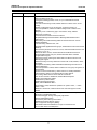
4.d2
24-Aug-06
Updates for iPECS release 4 software and LG-Nortel logo
General edits through-out.
Changed formatting (header, footer, etc.) for unified iPECS Manual
appearance.
CLI based Call Routing for DID, added reference to DID Lines in ICLID
routing.
Flexible configuration for up to 600 ports, covered in section 1.2.
Hunt Group Mailbox, referenced mailbox assignments in Station Hunt
Groups.
Multiparty voice conferencing (Up to 24 Parties in total), added to
Multi-Party Conference.
Conference Room Added Conference Room.
Simplified Message retrieval added to Message Wait/Call Back and
restructured.
Muted Ring w/Pre-Selected Msg added & restructured Pre & Custom
Display Messages.
T.38 Fax Relay, added IP FAX, T.38.
Day/Night Mode applied between groups, added reference and rewrote ICM
Tenancy.
ACD sections previously section 2.5 to 2.20, restructured ACD sections now
section 2.5.1~2.5.12.
Multi-level Admin access, restructured admin with Multi-level section.
Programmable Admin TCP port, restructured Web Admin & added
programmable tcp port.
Web User manual, multi-lingual, added Web User Manual section with
Multi-lingual support.
Network Security & Priority added new section with VLAN, Diffserv, IPSec
and SRTP.
Transparent Networking added Centralized Networking with Fail-over &
Remote Gateways.
Hunt Group Station Forward, added condition for Hunt group recognition of
forward state.
System Processor Redundancy, added section for standby MFIM600.
Call Recording, added unconditional Call recording feature.
IP Trunking, added SIP and H.323 with GK routed call
VSF section revised to VMIM/VSF, added VMIM description.
VMIM e-mail notification added
VMIM Back-up station added
VMIM multi-language support
MOH, added VMIM/VSF MOH
Authorization codes, added new operation for system codes, “* + table
index + code”.
Mobile Ext. enhanced, mobile receives hunt calls and support for Attd.
Recall.
4. d3
30-Sep-07
Updates for iPECS release 4 software (General edits for errata).
Emergency Call Attendant Alert
Automatic Daylight Savings Time (DST) Adjustment
Direct Inward Dialing (DID)
Automatic System Time Synchronization
Distributed Systems Network, paging
E-911 support for Emergency dialing
VSF/VMIM Outbound Notification to Pager or External Phone
TLS for Web Admin and Webphone
3
iPECS-LIK
Feature Description & Operation Manual
ISSUE
Issue 5.6
DATE
DESCRIPTION OF CHANGES
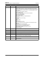
5.0
26-July-08
General updates & errata
Change “MFIM” references to “iPECS, include iPECS 50 and updated
capacity table Reference to VSF/VMIM announcement changed, expansion
from 20 to 70 codes, VSF MOH code 21 or 71) Multi-language code 22 or
72 throughout.
Updates for iPECS release 5 software
One-time DND forward
For TNET added paging reference and RTP description.
Device Zone Management
Call Coverage enhancement
SIP Extension support
Tenancy Group ring mode for Flexible DID/ICLID
Station ICR
Conference Group w/recording)
iP Bridge
Cabinet Alarm
NMS
System DECT
DISA Call Forward removed
Added LIP-8000 series soft key operation for auto dial features (LNR,
SAVE, etc.
Added Attendant active MFIM display
Updated Table 1.2-1 and updated VSF capacity
Call Forward using external number added
Added Option for voice mail attachment to e-mail
Change BGM operation
SMDR ICM added
5.0d1
07-Jan-09
Add in capacity table and Changed for iPECS-1200
5.0d2
17-Feb-09
Add group name for Terminal/Circular/VM/UCS.
5.0d3
13-Apr-09
Add condition 3 in 2.72.3.6 (Voice Mail Back-up Station).
5.0d4
12-May-09
Update for outgoing mailbox destination
5.0d5
02-Feb-10
Update description of DID call wait feature.
5.5
09-JUL-10
Updates for iPECS release 5.5B software
Add IP Watch timer for cpu redundancy and IPCR
5.5d1
30-DEC-10
Updates for iPECS release 5.5C software
5.6
01-NOV-11
Updates for iPECS release 5.6 software
Add IP-Attendant
4
iPECS-LIK
Feature Description & Operation Manual
Issue 5.6
Table of Contents
1. Introduction ......................................................................... 1
1.1 MANUAL APPLICATION ............................................................. 1
1.1.1 Organization ...........................................................................................1
1.1.2 Feature Information ................................................................................1
1.2 SYSTEM CAPACITIES ................................................................ 2
2. System ................................................................................. 5
2.1 ACCOUNT CODE ......................................................................... 5
2.2 ALARM SIGNAL/DOOR BELL .................................................... 7
2.3 AUTHORIZATION CODES (PASSWORD) .................................. 9
2.4 AUTO CALL RELEASE ............................................................. 12
2.5 AUTOMATIC CALL DISTRIBUTION (ACD) .............................. 13
2.5.1 Agents ...................................................................................................13
2.5.1.1 Agent Auto Connect/Zap Tone ........................................................... 13
2.5.1.2 Agent Id Login/Logout ......................................................................... 13
2.5.1.3 Agent Help Request ............................................................................ 15
2.5.1.4 Agent Queued Calls Display ............................................................... 16
2.5.1.5 Agent Automatic Wrap-Up .................................................................. 17
2.5.1.6 Agent On/Off Duty w/Reason Code .................................................... 18
2.5.2 Announcements ....................................................................................21
2.5.3 Auto ACD DND Unavailable Service ....................................................22
2.5.4 Calls-In-Queue routing ..........................................................................23
2.5.5 Calls-In-Queue Page Alert ....................................................................24
2.5.6 Event Messages ...................................................................................26
2.5.7 Group Mail Box .....................................................................................27
2.5.8 Group Name .........................................................................................28
2.5.9 Incoming Call Routing ...........................................................................29
2.5.10 ACD Caller Controlled ICLID Routing .................................................30
2.5.11 Supervisors .........................................................................................31
2.5.11.1 Supervisor Login/Logout ................................................................... 31
2.5.11.2 Supervisor Help Response ............................................................... 32
2.5.11.3 Agent Call Monitor ............................................................................ 33
2.5.11.4 Group Status Display ........................................................................ 34
2.5.11.5 Group Parameter Control ................................................................. 35
2.5.11.6 Agent Status Control ......................................................................... 36
2.5.12 ACD Statistics Report .........................................................................38
2.6 AUTOMATIC PAUSE INSERTION ............................................ 40
i
iPECS-LIK
Feature Description & Operation Manual
Issue 5.6
2.7 AUTOMATIC PRIVACY ............................................................. 41
2.8 AUTO SERVICE MODE CONTROL .......................................... 42
2.9 AUTOMATIC SYSTEM DAYLIGHT SAVINGS TIME ................ 43
2.10 AUTOMATIC SYSTEM TIME SYNCHRONIZATION ............... 44
2.11 BATTERY BACK-UP, MEMORY ............................................. 45
2.12 CALL FORWARD ..................................................................... 46
2.13 CALL FORWARD, PRESET .................................................... 50
2.14 CALL PARK ............................................................................. 52
2.15 CALL PICK-UP ......................................................................... 54
2.15.1 Directed Call Pick-Up ..........................................................................54
2.15.2 Group Call Pick-Up .............................................................................55
2.15.3 Pick Up Group Call Pick-Up ................................................................56
2.16 AUTO CALL RECORDING ...................................................... 58
2.17 CALL TRANSFER .................................................................... 59
2.17.1 Call Transfer, Station ..........................................................................59
2.17.2 Call Transfer, CO/IP ...........................................................................60
2.17.3 Call Transfer, Voice Mail .....................................................................62
2.18 CALL WAITING/CAMP-ON ...................................................... 63
2.19 CO/IP ACCESS ........................................................................ 64
2.20 CO/IP CALL TIME RESTRICTION ........................................... 66
2.21 CO/IP CALL WARNING TONE TIMER .................................... 67
2.22 CO/IP QUEUING ...................................................................... 68
2.23 CONFERENCE ......................................................................... 70
2.23.1 Conference Room ...............................................................................70
2.23.2 Multi-Party Voice Conference .............................................................72
2.23.3 Unsupervised Conference ..................................................................74
2.23.4 Conference Group ..............................................................................75
2.23.5 Conference Member VIEW & DELETE in Add_On_Conference ........77
2.24 CUSTOMER SITE NAME ......................................................... 79
2.25 DATA LINE SECURITY ............................................................ 80
2.26 DELAYED CO/IP RING ............................................................ 81
2.27 DELAYED AUTO ATTENDANT ............................................... 82
2.27.1 Ring Assigned Case ...........................................................................82
2.27.2 DISA Incoming Case (Russia Only) ....................................................82
ii
iPECS-LIK
Feature Description & Operation Manual
Issue 5.6
2.28 DIAGNOSTIC/MAINTENANCE ................................................ 84
2.29 DIAL-BY-NAME ........................................................................ 85
2.30 DIAL PULSE TO TONE SWITCHOVER .................................. 87
2.31 DIALING RESTRICTIONS ....................................................... 88
2.31.1 Class of Service ..................................................................................88
2.31.2 Day/Timed & Night Station COS .........................................................90
2.31.3 Temporary Station COS/Lock .............................................................91
2.31.4 Walking COS ......................................................................................93
2.32 DIFFERENTIAL RING .............................................................. 95
2.33 DND (DO NOT DISTURB) ........................................................ 97
2.34 DOOR OPEN ............................................................................ 99
2.35 EMERGENCY CALL E-911 (CALLER LOCATION) SUPPORT .
101
2.36 EMERGENCY CALL .............................................................. 103
2.37 EXECUTIVE/SECRETARY FORWARD ................................. 104
2.38 EXTERNAL AUTO ATTENDANT/VOICE MAIL .................... 106
2.38.1 AA/VM Group ....................................................................................106
2.38.2 In-band (DTMF) Signaling ................................................................107
2.38.3 SMDI (Simplified Msg Desk Interface) ..............................................107
2.38.4 Voice Mail Box Translation ...............................................................109
2.39 FLEXIBLE NUMBERING PLAN ............................................. 111
2.40 8 DIGITS ................................................................................. 112
2.41 HEADSET COMPATIBILITY .................................................. 113
2.42 HOLD ...................................................................................... 115
2.42.1 Hold Preference ................................................................................115
2.42.2 Hold Recall .......................................................................................115
2.42.3 Exclusive Hold ..................................................................................116
2.42.4 System Hold .....................................................................................118
2.42.5 Automatic Hold .................................................................................119
2.43 HOT DESK ............................................................................. 121
2.44 ICLID CALL ROUTING .......................................................... 123
2.45 IN-ROOM INDICATION .......................................................... 124
2.46 IP BRIDGE MODE .................................................................. 125
2.47 IP SYSTEM DECT .................................................................. 126
iii
iPECS-LIK
Feature Description & Operation Manual
Issue 5.6
2.48 IP FAX RELAY, T.38 SUPPORT ............................................ 127
2.49 IP TRANS-CODING ................................................................ 128
2.50 LNR (LAST NUMBER REDIAL) ............................................. 130
2.51 LCR (LEAST COST ROUTING) ............................................. 132
2.52 LINKED STATION PAIRS ...................................................... 134
2.53 LBC (LOUD BELL CONTROL) .............................................. 136
2.54 MOBILE EXTENSION ............................................................ 137
2.55 MULTIPLE LANGUAGE SUPPORT ...................................... 139
2.56 MULTIPLE VOICE MAILBOX SUPPORT .............................. 141
2.57 MOH (MUSIC-ON-HOLD) ....................................................... 142
2.58 NETWORK MANAGEMENT SYSTEM .................................. 144
2.59 NETWORK SECURITY & PRIORITY ..................................... 145
2.60 PRE-DEFINED & CUSTOM TEXT DISPLAY MESSAGES ... 146
2.60.1 DND operation in internal call to pre-selected station .......................149
2.61 REDUNDANT SYSTEM PROCESSOR ................................. 151
2.62 REGISTRATION & FRACTIONAL MODULE TABLES ......... 153
2.63 RINGING LINE PREFERENCE .............................................. 155
2.64 SPEED DIAL .......................................................................... 156
2.64.1 Display Security ................................................................................156
2.64.2 Speed Dial Pause Insertion ..............................................................156
2.64.3 Station Speed Dial ............................................................................157
2.64.4 System Speed Dial ...........................................................................160
2.64.5 System Speed Zone (Groups) ..........................................................163
2.65 STATION CALL COVERAGE ................................................ 164
2.66 STATION GROUPS ................................................................ 166
2.67 RING GROUPS INDICATION ................................................ 169
2.68 SMDR (STATION MESSAGE DETAIL RECORDING) .......... 170
2.68.1 Call Cost Display ..............................................................................170
2.68.2 SMDR Call Records ..........................................................................171
2.68.3 Lost Call Recording ..........................................................................174
2.69 SYSTEM ADMIN PROGRAMMING ....................................... 177
2.69.1 Keyset Administration .......................................................................177
2.69.2 Multi-Level Admin Access .................................................................177
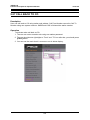
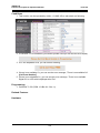
2.69.3 Web Administration ...........................................................................178
iv
iPECS-LIK
Feature Description & Operation Manual
Issue 5.6
2.69.4 Web User Manual .............................................................................179
2.70 SYSTEM NETWORKING ....................................................... 181
2.70.1 Centralized Control TNET .................................................................181
2.70.2 Distributed Control Network ..............................................................182
2.70.2.1 Net Call ........................................................................................... 183
2.70.2.2 Net Transfer .................................................................................... 184
2.70.2.3 Identification Service ....................................................................... 185
2.70.2.4 Call Completion .............................................................................. 185
2.70.2.5 Call Offer ......................................................................................... 186
2.70.2.6 Net Conference ............................................................................... 187
2.70.2.7 Message Waiting Indication (MWI) ................................................. 187
2.70.2.8 Net Call Forward – Unconditional ................................................... 188
2.70.2.9 Net Call Forward – Busy ................................................................. 189
2.70.2.10 Net Call Forward – No Answer ..................................................... 190
2.70.2.11 Net Call Forward – Busy / No Answer .......................................... 191
2.70.2.12 CO Transit-In ................................................................................ 192
2.70.2.13 CO Transit-Out ............................................................................. 192
2.70.2.14 BLF Presentation .......................................................................... 193
2.70.2.15 Do-Not-Disturb (DND) ................................................................... 194
2.70.2.16 (CAS) Attendant Call .................................................................... 195
2.70.2.17 Centralized Voice Mail .................................................................. 195
2.70.2.18 Paging to Networked System ....................................................... 196
2.71 TRAFFIC ANALYSIS ............................................................. 198
2.71.1 Traffic Analysis, Attendant ................................................................200
2.71.2 Traffic Analysis, Call Reports ............................................................201
2.71.3 Traffic Analysis, H/W Usage .............................................................202
2.71.4 Traffic Analysis, CO/IP Reports ........................................................203
2.72 UNIVERSAL NIGHT ANSWER (UNA) ................................... 205
2.73 VMIM/VSF INTEGRATED AUTO ATTD/VOICE MAIL .......... 206
2.73.1 VMIM/VSF ........................................................................................206
2.73.2 VMIM/VSF-Auto Attendant ...............................................................206
2.73.3 VMIM/VSF Voice Mail .......................................................................209
2.73.3.1 Message Storage ............................................................................ 209
2.73.3.2 Message Retrieval .......................................................................... 210
2.73.3.3 Remote Message Retrieval ............................................................ 212
2.73.3.4 Message Retrieval Options ............................................................. 213
2.73.3.5 E-Mail Notification ........................................................................... 214
2.73.3.6 Voice Mail Back-up Station ............................................................. 216
2.73.3.7 Voice Mailbox Settings ................................................................... 216
2.73.3.8 Call Forward from VM ..................................................................... 218
2.73.3.9 Outbound Message Notification ...................................................... 219
2.73.4 System Voice Memo .........................................................................220
2.73.5 Company Directory ...........................................................................222
2.73.6 Record VM Greeting using CCR .......................................................223
2.73.7 Administrator Mailbox .......................................................................224
v
iPECS-LIK
Feature Description & Operation Manual
Issue 5.6
2.73.8 Announce Only Mailbox ....................................................................226
2.73.9 Message Cascade ............................................................................226
2.73.10 Class of Service Settings ................................................................227
2.73.11 Send Message ................................................................................228
2.73.12 Distribution Lists .............................................................................229
2.73.13 Mark a message private .................................................................230
2.73.14 Mark a message for delivery confirmation ......................................231
2.74 WAKE-UP ALARM (ONE TIME WAKE UP ALARM) ............ 233
2.75 WAKE-UP ALARM (FIVE TIME WAKE UP ALARM) ............ 235
2.76 ZONE HOLIDAY ASSIGNMENT ............................................ 237
2.77 REMOTE DEVICE ZONE MANAGEMENT ............................ 238
2.78 ZONE CALL AND CONNECTION NUMBER LIMIT .............. 239
2.78.1 Zone Outgoing CO call Number Limit ...............................................239
2.78.2 Inter Zone Connection Number Limit ................................................239
2.79 SYSTEM CALL ROUTING ..................................................... 241
2.80 CO CALL REROUTING ......................................................... 243
2.81 OUTGOING MAILBOX DESTINATION ................................. 245
2.82 REMOTE CONTROL WITH MOBILE EXTENSION ............... 246
2.83 PREFIX DIALING TABLE ...................................................... 247
2.84 IP CALL RECORDING ........................................................... 249
2.85 3RD PARTY CALL RECORDING ........................................... 250
2.86 FORCED DISCONNECT BUTTON (EMERGENCY
SUPERVISOR BUTTON) ......................................................... 251
2.87 CALL BACK TO CO ............................................................... 253
2.88 PERSONAL GROUP .............................................................. 255
3. Intercom .......................................................................... 257
3.1 DIRECT STATION SELECT/BUSY LAMP FIELD (DSS/BLF) 257
3.2 INTERCOM CALL (ICM CALL) ................................................ 258
3.3 INTERCOM CALL HOLD ......................................................... 260
3.4 INTERCOM CALLER CONTROLLED ICM SIGNALING ......... 261
3.5 INTERCOM LOCK-OUT ........................................................... 262
3.6 INTERCOM STEP CALL .......................................................... 263
vi
iPECS-LIK
Feature Description & Operation Manual
Issue 5.6
3.7 INTERCOM TENANCY GROUP .............................................. 264
3.8 INTERCOM TRANSFER .......................................................... 266
3.9 MESSAGE WAIT/CALL BACK ................................................ 268
3.9.1 CLI Message Wait ..............................................................................268
3.9.2 Short Message Service (SMS) ...........................................................270
3.9.3 Station Message Wait/Call Back .........................................................272
3.9.4 Message Wait Reminder Tone ...........................................................275
3.10 PAGING .................................................................................. 276
3.10.1 Internal/External & All Call Page .......................................................276
3.10.2 Meet Me Page Answer .....................................................................278
3.10.3 SOS Paging ......................................................................................279
3.11 PUSH-TO-TALK PAGING ...................................................... 280
3.12 BARGE IN .............................................................................. 282
4. CO/IP ................................................................................ 283
4.1 AUTO FAULT DETECTION AND RECOVERY ....................... 283
4.2 CO LINE FLASH ...................................................................... 284
4.3 CO/IP LINE GROUPS .............................................................. 285
4.4 CO/IP LINE PRESET FORWARD ............................................ 286
4.5 CO/IP RING ASSIGNMENT ..................................................... 287
4.6 CO LINE RELEASE GUARD TIME .......................................... 288
4.7 CO RING DETECT ................................................................... 289
4.8 DIAL PULSE SIGNALING ........................................................ 290
4.9 DIRECT INWARD DIAL (DID) .................................................. 291
4.10 DIRECT INWARD SYSTEM ACCESS (DISA) ....................... 293
4.11 DTMF SIGNAL SENDING ...................................................... 295
4.12 IP ADDRESS DIALING .......................................................... 296
4.13 IP TRUNKING ......................................................................... 297
4.13.1 H.323 v4 Service ..............................................................................297
4.13.2 SIP Service .......................................................................................298
4.14 IP WAN DIALING AFTER ANSWER ..................................... 300
4.15 ISDN (INTEGRATED SERVICE DIGITAL NETWORK) ......... 301
4.15.1 ISDN AOC (Advice of Charge) .........................................................301
4.15.2 Calling/Called Party Identification .....................................................302
vii
iPECS-LIK
Feature Description & Operation Manual
Issue 5.6
4.15.3 Keypad Facility .................................................................................303
4.15.4 Multiple Subscriber Number (MSN) ..................................................304
4.16 ISDN SUPPLEMENTARY SERVICES ................................... 307
4.16.1 ISDN Call Deflection .........................................................................307
4.16.2 ISDN Malicious Call Id Request ........................................................308
4.17 PRIVATE LINE ....................................................................... 309
4.18 MULTIPLE CLI ....................................................................... 311
5. iPECS Phone ................................................................... 313
5.1 ANSWERING MACHINE EMULATION ................................... 313
5.2 AUTO CALLED NUMBER REDIAL (ACNR) ........................... 315
5.3 AUTO RELEASE OF [SPEAKER] ........................................... 317
5.4 AUTOMATIC SPEAKER SELECT ........................................... 318
5.5 BACK GROUND MUSIC .......................................................... 319
5.6 CALL LOG DISPLAY ............................................................... 321
5.7 CO LINE NAME DISPLAY ....................................................... 322
5.8 DID CALL WAIT ....................................................................... 323
5.9 DND - ONE TIME DND ............................................................. 324
5.10 FLEX BUTTON DIRECT SPEED DIAL ASSIGNMENT ......... 326
5.11 FLEXIBLE LED FLASH RATES ............................................ 327
5.12 GROUP LISTENING ............................................................... 328
5.13 STATION INDIVIDUAL CALL ROUTING (ICR) ..................... 329
5.14 CALL PROFILE ...................................................................... 331
5.15 INTERCOM SIGNALING MODE ............................................ 334
5.16 MUTE ...................................................................................... 336
5.17 OFF-HOOK SIGNALING ........................................................ 337
5.18 ON-HOOK DIALING ............................................................... 338
5.19 PRIME LINE IMMEDIATELY/DELAYED ............................... 339
5.20 RING TONE DOWNLOAD ..................................................... 341
5.21 SAVE NUMBER REDIAL (SNR) ............................................ 342
5.22 SILENT TEXT MESSAGE ...................................................... 344
5.23 SPEAKERPHONE .................................................................. 345
viii
iPECS-LIK
Feature Description & Operation Manual
Issue 5.6
5.24 STATION FLEXIBLE BUTTONS ........................................... 347
5.25 STATION RELOCATION ....................................................... 349
5.26 STATION USER PROGRAMMING & CODES ....................... 350
5.27 TWO-WAY RECORD ............................................................. 356
5.28 VOICE OVER .......................................................................... 358
5.29 SERIAL DSS .......................................................................... 360
6. Attendants ....................................................................... 362
6.1 ACTIVE CPU (MFIM) DISPLAY ............................................... 362
6.2 ALTERNATE ATTENDANT ..................................................... 363
6.3 ATTENDANT POSITIONS ....................................................... 364
6.4 ATTENDANT RECALL ............................................................ 365
6.5 ATTENDANT STATION PROGRAM CODES .......................... 366
6.6 CABINET ALARM .................................................................... 369
6.7 CALL FORWARD, ATTENDANT ............................................. 370
6.8 CALL FORWARD CO/IP OFF-NET ......................................... 371
6.9 CALL/QUEUING ....................................................................... 373
6.10 DAY/NIGHT/TIMED/SCENARIO RING MODE ...................... 374
6.11 DSS CONSOLES ................................................................... 376
6.12 DISABLE OUTGOING CO/IP ACCESS ................................. 380
6.13 DND OVERRIDE .................................................................... 381
6.14 EMERGENCY CALL ATTENDANT ALERT .......................... 382
6.15 EZ-ATTENDANT .................................................................... 384
6.16 FEATURE CANCEL ............................................................... 385
6.17 INTRUSION ............................................................................ 386
6.18 LCD DISPLAY FORMAT CONTROL ..................................... 387
6.19 SYSTEM CLOCK SET ........................................................... 388
6.20 IP-ATTENDANT ..................................................................... 390
7. SLT ................................................................................... 391
7.1 BROKER CALL ........................................................................ 391
ix
iPECS-LIK
Feature Description & Operation Manual
Issue 5.6
7.2 HOWLER TONE ....................................................................... 393
7.3 SLT MESSAGE WAIT INDICATION ........................................ 394
7.4 SLT NAME ENTRY .................................................................. 395
7.5 TRANSFER CLI TO SLT .......................................................... 396
7.6 SLT FLASH MODE .................................................................. 397
8. SIP Extension .................................................................. 398
8.1 REGISTRATION ....................................................................... 398
8.2 PROVISIONING ........................................................................ 405
8.3 MAKE CALL ............................................................................. 409
8.4 CALL ANSWER ....................................................................... 411
8.5 CALL HOLD ............................................................................. 412
8.6 CALL TRANSFER .................................................................... 413
8.7 CALL FORWARD ..................................................................... 414
8.8 DO NOT DISTURB (DND) ........................................................ 415
8.9 CONFERENCE ......................................................................... 416
8.10 CALL WAIT & BROKER CALL ............................................. 417
8.11 CALL PARK ........................................................................... 418
8.12 MCIM REQUIREMENT FOR SIP PHONE .............................. 419
8.13 VOIP OR VOIM8/24 REQUIREMENT FOR SIP PHONE ....... 420
8.14 CALL TRACE OF SIP EXTENSION FOR DEBUGGING ....... 421
8.15 DSS/BLF (BUSY LAMP FIELD) ............................................. 422
8.16 SIP VIDEO CALL ................................................................... 423
8.17 SIP VIRTUAL MOBILE EXTENSION (VMEX) ....................... 424
8.18 SIP VIRTUAL CO LINE (VCOL) ............................................. 432
x
iPECS-LIK
Feature Description & Operation Manual
Issue 5.6
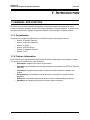
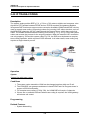
1. INTRODUCTION
1.1 MANUAL APPLICATION
This document provides detailed information covering description and operation of the
numerous features available in the iPECS Series Release 5 system software. The document
is written assuming the system employs the default-numbering plan for North America.
1.1.1 Organization
Features are arranged alphabetically in six different major groupings as follows:
• Section 2 System Features
• Section 3 Intercom Features
• Section 4 CO/IP
• Section 5 iPECS Phone
• Section 6 Attendant Position
• Section 7 SLT
1.1.2 Feature Information
Each section is an alphabetical listing of features with the description and operation of each.
The structure is divided into 6 parts as below:
• Description: explains the nature of the feature.
• Operation: gives detailed step-by-step operation of the feature for iEPCS IP Phones
and SLTs.
• Conditions: explains known feature interactions and constraints related to the
feature.
• Programming: lists database entries that may be required for proper feature
operation.
• Reference: lists related topical information to aid in understanding the feature.
• Hardware: lists hardware required for proper feature operation.
1
iPECS-LIK
Feature Description & Operation Manual
Issue 5.6
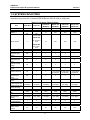
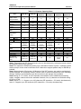
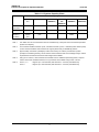
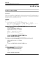
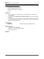
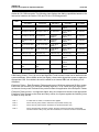
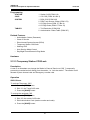
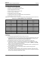
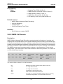
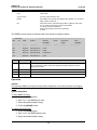
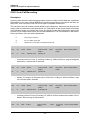
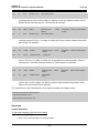
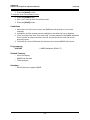
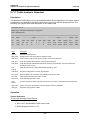
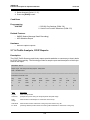
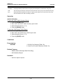
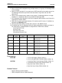
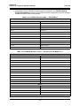
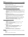
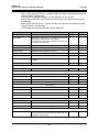
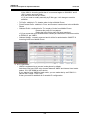
1.2 SYSTEM CAPACITIES
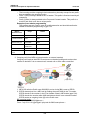
The iPECS Series is available in several configurations as listed in Table 1.2-1. Total port
capacities range from the 31-channel iPECS-Micro to iPECS-1200 at 1200 ports.
Table 1.2-1 System Capacity Chart
Item
Main Cabinet
System Ports
Stations*1
iPECS-Micro
iPECS-50
n/a
31 ports
26 w/2 SLT
std.
n/a
50 ports
50 w/2 SLT
std.
iPECS-100
iPECS- 300
iPECS-600
iPECS-1200
(MFIM100)
(MFIM300)
(MFIM600)
(MFIM1200)
10 slots
100 ports
10 slots
300 ports
10 slots
600 ports
10 slots
1200 ports
70
300
600
1200
42
200
400
600
35
4
150
5
300
5
600
5
max 42, basic
iPECS 50A
PSTN circuits*1
5
std. 4 PSTN +
VoIP
Max. RSGMs*2
Attendants
13
4
iPECS 50B
std. 4 BRI +
VoIP
25
4
Serial Port (RS232C)
USB Host port
n/a
1
1
1
1
1
1
1
1
1
1
1
Alarm/Door bell
input
n/a
1
2
2
2
2
External Control
Relays
Music Source
Inputs
n/a
1
2
4
4
4
n/a
1
2
2
2
2
Power Fail Circuit
n/a
1
4
External Page
zones
Internal Page
Zones
n/a
1
2
2
2
2
10
10
10
35
35
100
800
(23 digits)
800
(23 digits)
800
(23 digits)
3000
(23 digits)
6000
(23 digits)
12000
(23 digits)
10
10
10
20
50
20 (23 digits)
20 (23 digits)
1000
1000
4000
8000
24000
10 (23 digits)
10 (23 digits)
10 (23 digits)
10 (23 digits)
10 (23 digits)
1 (23 digits)
1 (23 digits)
1 (23 digits)
1 (23 digits)
1 (23 digits)
1 (23 digits)
1
3
3
9
9
9
5000
20
5000
20
5000
20
10000
72
15000
72
30000
200
12
40
40
48
48
100
System Speed Dial
System Speed Dial
10
Zones (Groups)
Station Speed Dial 20 (23 digits)
Total station speed
1000
dial
Last Number Redial 10 (23 digits)
Save Number
Redial
DSS
Consoles/Station
SMDR buffer
CO Line Groups
Station & Hunt
Groups
2
4 + Ext. PFTU 4 + Ext. PFTU 4 + Ext. PFTU
(6 optional)
(6 optional)
(6 optional)
100 (23 digits) 100 (23 digits) 100 (23 digits)
iPECS-LIK
Feature Description & Operation Manual
Issue 5.6
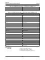
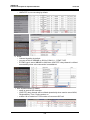
Table 1.2-1 System Capacity Chart
iPECS-100
iPECS- 300
iPECS-600
iPECS-1200
(MFIM100)
(MFIM300)
(MFIM600)
(MFIM1200)
50
70
70
70
200
20
20
30
100
150
200
26
50
70
300
600
1200
20
20
20
40
80
160
25
25
35
150
300
600
10
10
10
36
36
100
26
474
500
50
450
500
70
430
500
300
700
1000
600
1400
2000
1200
2800
4000
280(245)
minutes
(4 channels)
280(245)
minutes
(6 channels)
210(175)
minutes
(6 channels)
210(175)
minutes
(6 channels)
n/a
n/a
n/a
9 hrs
9 hrs
9 hrs
MCIM
WTIM
VoIP channels*4
Redundancy
1
16
5 std.
No
2
16
Std. 4-8
No
2
16
6 std.
Yes
4
32
6 std.
Yes
SIP channels
(Stations + CO
lines)
Same as
system port
Same as
system port
100
200
Item
iPECS-Micro
iPECS-50
Station & Hunt
Group Members
Pickup Group
Pickup Group
Member
Conf. Grps System
Station
Executive/Secretary
pairs
26
Authorization
Codes
Station
System
Total
VSF*3
VMIM
9 hrs, max x 6 9 hrs, max x 30
8
30
32
32
n/a
n/a
Yes
Yes
200/100
Note5
500
Note 1 The station and CO Line maximums are not simultaneously; total ports cannot exceed
the specified System Port capacity.
Note 2 For maximum RSGM connection ports, calculation formula is ports = available system
station ports)/2, there must be sufficient VoIP channels to support packet relay for RSGM rtp
packets.
Note 3 Approximately 35 minutes (16 Mbytes) of the VSF memory are used to provide basic
system prompts, the remaining memory can be used for announcements and voice message
storage. Values in parenthesis are the announcement and storage time available.
Note 4 Using G.711 codecs, 8 VoIP channels are available. Due to additional processing
needs, complex codecs reduce the available channels; four (4) channels are available using
G.723 or G.729.
Note 5 Issue 0, 1, 2 : Support up to 100 channels (SIP extension + CO trunk) simultaneously
Issue 3 : Support up to 200 channels (SIP extension + CO trunk) simultaneously
3
iPECS-LIK
Feature Description & Operation Manual
Issue 5.6
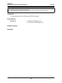
Table 1.2-1 System Capacity Chart
Item
Capacity
iPECS-Mi
cro
iPECS-50
iPECS-100
(MFIM100)
iPECS300
(MFIM300)
iPECS-600
(MFIM600)
iPECS-1200
(MFIM1200)
5 std.
Std. 4-8
6 std.
6 std
n/a
n/a
Redundancy
No
No
Yes
Yes
Yes
Yes
SIP channels
(Stations +
CO lines)
Same as
system
port
Same as system
port
100
200
200/100
Note5
500
VoIP
channels*4
Note 1
The station and CO Line maximums are not simultaneously; total ports cannot exceed the specified
System Port capacity.
Note 2
For maximum RSGM connection ports, calculation formula is ports = available system station ports)/
2, there must be sufficient VoIP channels to support packet relay for RSGM rtp packets.
Note 3
Approximately 35 minutes (16 Mbytes) of the VSF memory are used to provide basic system
prompts, the remaining memory can be used for announcements and voice message storage. Values
in parenthesis are the announcement and storage time available.
Note 4
Using G.711 codecs, 8 VoIP channels are available. Due to additional processing needs, complex
codecs reduce the available channels; four (4) channels are available using G.723 or G.729.
Note 5
Issue 0, 1, 2
: Support up to 100 channels (SIP extension + CO trunk) simultaneously
Issue 3
: Support up to 200 channels (SIP extension + CO trunk) simultaneously
4
iPECS-LIK
Feature Description & Operation Manual
Issue 5.6
2. SYSTEM
2.1 ACCOUNT CODE
Description
Station users may allow tracking of specific calls by entering a non-verified variable length (up
to 12 digits) identifier for a call. The identifier or “Account Code” is output as part of the Station
Message Detail Record (SMDR) for the call.
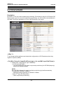
Operation
iPECS Phone
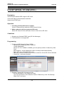
To assign a Flex button for {ACCOUNT CODE} operation:
{ACCOUNT CODE} button: [PGM] + {FLEX} + [PGM] + ‘84’ + [SAVE]
{ONE-TOUCH ACCOUNT CODE} button: [PGM] + {FLEX} + [PGM] + ‘84’ + Account
code (up to 12 digits) + [SAVE]
To enter an Account Code using an {ACCOUNT CODE} button prior to placing a call:
1. Lift the handset.
2. Press the {ACCOUNT CODE} button.
3. Dial the Account Code (1 to 12 digits).
4. Press ‘*’, Intercom dial tone is heard.
5. Place the CO/IP call as normal.
Or,
1. Lift the handset or press the [SPEAKER] button.
2. Press the {ONE-TOUCH ACCOUNT CODE} button.
3. Place the CO/IP call as normal.
To enter an Account Code using an {ACCOUNT CODE} button during a call:
1. Press the {ACCOUNT CODE} button.
2. Dial the Account Code (1 to 12 digits).
3. Press ‘*’.
Or,
1. Press the {ONE-TOUCH ACCOUNT CODE} button.
SLT
To enter an Account Code prior to placing a call:
1. Lift the handset.
2. Dial Flex Numbering Plan code ‘550’.
3. Dial the Account Code (1 to 12 digits).
4. Press ‘*’.
5. Place the CO/IP call as normal.
5
iPECS-LIK
Feature Description & Operation Manual
Issue 5.6
To enter an Account Code during a call:
1. Momentarily press the Hook-switch.
2. Dial Flex Numbering Plan code ‘550’.
3. Dial the Account Code (1 to 12 digits).
4. Press ‘*’.
Conditions
1. When entering an Account Code during a call, DTMF digits are not heard by the
connected party.
2. A maximum of 1000 {ONE-TOUCH ACCOUNT CODE} buttons may be assigned in
the system.
3. If an Authorization Code is entered as the Account Code, the SMDR record will show
the station number or the bin number for a System Authorization Code rather than the
user entered Authorization Code.
Programming
NUMBERING
1 Flexible Numbering Plan (PGM 106-Btn 8)
Related Features
• Authorization Codes (Password)
• SMDR (Station Message Detail Recording)
• Station Flexible Buttons
Hardware
6
iPECS-LIK
Feature Description & Operation Manual
Issue 5.6
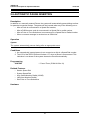
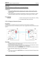
2.2 ALARM SIGNAL/DOOR BELL
Description
The system can be configured to recognize the status of an external contact (normally open or
closed). The system will signal assigned iPECS Phones when the contact activates. This
capability is commonly employed to provide remote Alarm or Door Bell signals to the user.
Assigned stations receive the Alarm Signal, either a single tone burst repeated at 1-minute
intervals or a continuous tone. The Alarm Signal may be terminated at the user’s phone by
dialing the Alarm Stop code or, if assigned, pressing the {ALARM STOP} button. To rearm the
Alarm function, the alarm condition must be cleared and the Alarm signal terminated.
When used as a Door Bell, assigned iPECS Phones receive a single tone burst each time the
external contact is activated and no reset is required.
Operation
System
At detection of contact operation, the Alarm/Door Bell signal is sent to assigned stations.
iPECS Phone
To assign a Flex button as an {ALARM STOP} button to terminate the Alarm Signal:
[PGM] + {FLEX} + ‘565’ + [SAVE]
To terminate an Alarm Signal while idle:
1. Dial the Flex Numbering Plan code 565, confirmation tone is received and the Alarm
Signal is terminated. If the alarm condition is cleared, the system will automatically
rearm the alarm monitoring.
Or,
1. Press the {ALARM STOP} button.
Conditions
1. The Alarm contacts must be “dry”, no voltage or current source connected.
2. Only an iPECS Phone may be assigned to receive Alarm/Door Bell signals.
3. An iPECS Phone with LCD assigned to receive Alarm/Door Bell signals will show
“ALARM” or “DOOR BELL” as appropriate.
Programming
SYSTEM
STATION
1
2
3
4
1
Alarm Enable (PGM 163-Btn 1)
Alarm Contact Type (PGM 163-Btn 2)
Alarm/Doorbell Mode (PGM 163-Btn 3)
Alarm Signal Mode (PGM 163-Btn 4)
Alarm/Door Bell Attribute (PGM 113-Btn 8)
Related Features
• Door Open
7
iPECS-LIK
Feature Description & Operation Manual
Issue 5.6
Hardware
• iPECS Phone
• External contact connected to Alarm input of MFIM, refer to iPECS Hardware
Description & Installation Manual.
8
iPECS-LIK
Feature Description & Operation Manual
Issue 5.6
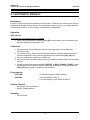
2.3 AUTHORIZATION CODES (PASSWORD)
Description
Authorization Codes provide a means to control access to Off Premise Call Forward, Walking
COS, or DISA and may be required for outgoing CO/IP Line or LCR access based on
configuration of the iPECS database. When users dial an Authorization Code that matches an
Authorization Code stored in the database, the system invokes the Station COS or the COS
assigned to Authorization code. Each Authorization code has separate Day/Night mode COS
assignments.
There are two types of Authorization Codes, Station and System. A Station Authorization Code
is specifically related to a given station and intended for a single user. The System
Authorization Codes are intended for use by any station in the system.
The Station Authorization Codes includes the associated station number and the assigned
code. The structure of the System Authorization code can be set as either “*”, or “*” the
Authorization table index and the code digits. The later allows duplicate codes to be employed
using entry of table index to provide a unique identification of the entry.
The Administrator and Attendants are permitted to assign any Authorization code including
codes for another station. Normal users may only assign the Station Authorization code for the
specific station.
Operation
iPECS Phone
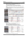
To assign a Station Authorization Code:
1. Press the [PGM] button.
2. Dial ‘33’, the Authorization Code Program Code.
3. Dial the Station number.
4. Dial the Authorization Code (1 to 12 digits).
5. Press the [SAVE] button.
To enter an Authorization Code when second dial tone is received:
1. Dial the station number for the Station Authorization code or, for a System
Authorization Code, dial ‘*’ or ‘*’ and the Authorization table index.
2. Dial the corresponding Authorization Code.
3. Place call as normal.
SLT
To assign a Station Authorization code:
1. Lift the handset.
2. Dial SLT Program Mode Entry code ‘561’.
3. Dial Station User Program code ‘33’.
4. Dial Authorization Code (1 to 12 digits).
5. Momentarily press the Hook-switch, receive confirmation tone.
9
iPECS-LIK
Feature Description & Operation Manual
Issue 5.6
To enter an Authorization Code when second dial tone is received;
1. Dial the station number for the Station Authorization code or, for a System
Authorization Code, dial ‘*’ or ‘*’ and the Authorization table index.
2. Dial the corresponding Authorization Code.
3. Momentarily press the Hook-switch.
4. Place call as normal.
DISA
To enter an Authorization Code when second dial tone is received:
1. Dial the station number for a Station Authorization code or, for a System code, ‘*’ or ‘*’
and the Authorization table index,
2. Dial the corresponding Authorization Code.
3. Place call as normal.
System Attendant
To assign an Authorization Code:
1. Press the [PGM] button.
2. Dial Attendant Station Program Code ‘031’.
3. Dial station number for a Station code or, for system code, ‘*’ or ‘*’ and the
Authorization table index.
4. Dial Authorization Code.
5. Press the [SAVE] button.
Conditions
1. When a DISA Line is marked for Authorization Code entry, the caller will hear DND
Warning tone and must input a valid Authorization Code to continue. In case of an
entry error, the user may retry entry of the code. In case of multiple entry errors, the
user may retry entry based on the DISA Retry counter. The station, if assigned, is
forced to COS 7 after repeated attempts fail.
2. A user must enter a valid code within the number of attempts assigned as the FAC
(Forced Account Code) Retry Count. The station, if enabled, is placed to COS 7 after
repeated failure attempts.
3. A user may enter an Authorization Code from any station to place a CO/IP call using
Walking COS.
4. The default Station Authorization code is the station number and “*”.
5. The total number of Authorization codes is provided in Table 1.2-1.
6. CO/IP groups may be configured to require entry of a valid Authorization Code. In this
case, a second dial tone is provided when the CO/IP group is accessed. If the code
entered is invalid, error tone is returned and the user must enter a valid code within
the FAC Retry Count.
7. If the Check Password option is enabled in the LCR database, when dialed digits
match the LDT table digits, the system will send second dial tone to request the user
input a valid Authorization code.
8. An Authorization code may include any dial pad digit except “*” and ‘#’.
10
iPECS-LIK
Feature Description & Operation Manual
Issue 5.6
9. Duplicate or conflicting System Authorization codes are not allowed when using the
older “*” and code operation. For example, code “1234” conflicts with code “123” and
cannot be recognized as a unique code. Since the index operation employs the table
index and the station number forms part of the Station code, conflicts will not occur
and duplicate codes are allowed for these types of Authorization code.
10.Use of Authorization codes varies based on the system nation code. In some regions,
particularly the US and UK, a System Authorization code may be required for DISA
access. Entering a Station code on a DISA line will fail in these areas. In other regions,
a System Authorization code can be used with Walking COS.
11.In case of System Authorization code, there is a system base admin option - End code
(#) usage in System Auth Code (PGM 160 – Btn 26).
If this value is set to ON, user must enter End Code (#) after entering authorization
code.
Programming
STATION
CO/IP
SYSTEM
TABLES
1
1
2
1
2
3
4
5
Station Account (PGM 112-Btn 19)
CO/IP Group Authorization (PGM 141-Btn 8)
DISA Authorization Code (PGM 142-Btn 5)
DISA Retry Counter (PGM 160-Btn 5)
FAC Retry Count (PGM 160-Btn 16)
Old Auth Code Use (PGM 161-Btn 16)
COS 7 When Auth fails (PGM 161-Btn 17)
End code(#) usage in System Auth Code (PGM 160
– Btn 26)
1 LCR Check Password (PGM 221-Btn 6)
2 Station Authorization Code Table (PGM 227)
Related Features
•
•
•
•
•
•
•
•
•
Account Code
Auto Service Mode Control
Direct Inward System Access (DISA)
CO/IP Line Groups
CO/IP Access
Temporary Station COS/Lock
Walking COS
Call Forward
Station User Programming & Codes
Hardware
11
iPECS-LIK
Feature Description & Operation Manual
Issue 5.6
2.4 AUTO CALL RELEASE
Description
CO/IP or intercom calls (except Hands-free Answerback), will be released automatically if the
user does not complete dialing or, for intercom calls, the called party does not answer after a
pre-determined time.
Operation
System
Auto Call Release of Intercom calls:
If a station places an intercom call and the called station does not answer in the Intercom
Call Release Time, the call is terminated and the calling user receives error tone.
Auto Call Release of CO/IP calls:
If a station seizes an idle CO/IP Line and does not dial within the CO/IP Call Automatic
Release Time, the call is terminated and the user will receive error tone.
Conditions
1. If the Automatic Call Release Timer is set to ‘0’, Auto Call Release is disabled.
2. When the handset is used to place a call, the user will receive error tone for 30
seconds followed by 30 seconds of Howler tone and the station is placed in a fault
mode. If on-hook dialing is used, the station receives error tone for one (1) second and
returns to idle automatically.
Programming
STATION
SYSTEM
1 Howling Tone to Stn (PGM 111-Btn 5)
1 CO Call Automatic Release Timer (PGM 180-Btn 12)
2 Intercom Call Automatic Release Timer (PGM
182-Btn 4)
Related Features
• Howler Tone
Hardware
12
iPECS-LIK
Feature Description & Operation Manual
Issue 5.6
2.5 AUTOMATIC CALL DISTRIBUTION (ACD)
Description
iPECS ACD incorporates flexible incoming call routing, real-time agent monitoring and
supervision, and call record statistics as well as ACD Event messages for management
reporting. Calls route to an ACD group directly or otherwise including via call transfer, CCR and
ICLID routing.
2.5.1 Agents
2.5.1.1 Agent Auto Connect/Zap Tone
Description
Agents using a headset can have calls from enabled ACD groups connected to them
automatically. This feature removes the requirement for the agent to answer ACD calls
manually. The Agent receives a short tone (Zap Tone), if assigned, and is then connected to
the ACD caller.
Operation
System
When Zap tone is enabled, operation of this feature is automatic.
Conditions
1. The station must be in the headset mode for this feature to operate.
Programming
STATION GROUPS
1 ACD Group (PGM 191)
2 Zap Tone (PGM 191-Btn 24-1)
Related Features
• Station Groups
Hardware
• iPECS Phone
2.5.1.2 Agent Id Login/Logout
Description
Stations or 4-digit Agent Ids are assigned as members of an ACD group. A station or Agent ID
can be assigned to a maximum of two (2) ACD groups. Each Agent has a unique 4-digit Agent
Id used to login and logout of active ACD group participation. Agents can login from any station
13
iPECS-LIK
Feature Description & Operation Manual
Issue 5.6
in the system but only at one station. When an Agent logs in, any active login for the Agent is
terminated and the new login is honored. An Agent may login to two (2) groups at one time,
logging into and out of the primary and secondary group separately.
Operation
Agent iPECS Phone
To assign {LOGIN} or {LOGOUT} buttons:
1. [PGM] + {FLEX} + Login or Logout code + ACD Group Number (optional) + [SAVE]
To Login to a primary group using the Agent Id;
1. Lift handset or press [SPEAKER] button,
2. Dial ‘581’ the ACD Agent Primary Login code or press the Login Flex button,
3. Dial the ACD group number,
4. Dial the Agent ID, the agent is logged into the ACD group.
To Logout of the primary ACD Group;
1. Lift handset or press [SPEAKER] button,
2. Dial ‘582’ the ACD Agent Primary Logout code or press the Logout Flex button,
3. Dial the ACD group number,
4. Dial the Agent ID, the agent is logged into the ACD group.
To Login to a secondary group using the Agent Id;
1. Lift handset or press [SPEAKER] button,
2. Dial ‘583’ the ACD Agent Secondary Login code or press the Login Flex button,
3. Dial the ACD group number,
4. Dial the Agent ID, the agent is logged into the ACD group.
To Logout of the secondary ACD Group;
1. Lift handset or press [SPEAKER] button,
2. Dial ‘584’ the ACD Agent Secondary Logout code or press the Logout Flex button,
3. Dial the ACD group number,
4. Dial the Agent ID, the agent is logged out of the ACD Group.
SLT
To Login to a primary group using the Agent Id;
1. Lift handset,
2. Dial ‘581’ the ACD Agent Primary Login code,
3. Dial the ACD group number
4. Dial the Agent ID, the agent is logged into the ACD group.
To Logout of the primary ACD Group;
1. Lift handset,
2. Dial ‘582’ the ACD Agent Primary Logout code.
3. Dial the ACD group number
4. Dial the Agent ID, the agent is logged out of the ACD Group.
14
iPECS-LIK
Feature Description & Operation Manual
Issue 5.6
To Login to a secondary group using the Agent Id;
1. Lift handset,
2. Dial ‘583’ the ACD Agent Secondary Login code,
3. Dial the ACD group number
4. Dial the Agent ID, the agent is logged into the ACD group.
To Logout of the secondary ACD Group;
1. Lift handset,
2. Dial ‘584’ the ACD Agent Secondary Logout code.
3. Dial the ACD group number,
4. Dial the Agent ID, the agent is logged out of the ACD Group.
Conditions
1. The system outputs ACD events including Login/Logout messages when Discovery
Manager Print is enabled.
2. The Agent Id can be any 4-digit number (0000-9999). iPECS does not verify the Agent
Id, other than requiring that four digits be entered.
3. Any Agent Id may be used to login except at a Hot Desk station where the user
Authorization code is required.
Programming
NUMBERING PLAN
STATION GROUPS
SYSTEM
1
2
3
4
1
1
2
ACD Agent Primary Login code (PGM 109-Btn 5)
ACD Agent Primary Logout code (PGM 109-Btn 6)
ACD Agent Secondary Login code (PGM 109-Btn 7)
ACD Agent Secondary Logout code (PGM 109-Btn 8)
ACD Group (PGM 191)
Discovery Manager Print (PGM 160-Btn 13)
Application Interface Msg (PGM 161-Btn 18)
Related Features
• Station Groups
• Hot Desk
• Authorization Codes (Password)
Hardware
2.5.1.3 Agent Help Request
Description
Agents request assistance from a Supervisor using the ACD Help Code, default 574. Using
iPECS Phones, agents with the {HELP} button can request assistance without interrupting an
active conversation.
15
iPECS-LIK
Feature Description & Operation Manual
Issue 5.6
Operation
Agent iPECS Phone
To assign {HELP} buttons:
1. [PGM] + {FLEX} + ‘574’ + ACD Group Number (optional) + [SAVE]
To request Supervisor assistance while on an active ACD call,
1. Press the {HELP} button.
SLT
To request Supervisor assistance while on an active ACD call,
1. Hook-flash.
2. Dial ‘574’, the Agent Help code.
3. Dial the desired ACD Group number.
Conditions
1. Agents receive error tone to indicate there is no active Supervisor.
2. Using the {HELP} button during a call, no signals are sent on the active conversation
and the connected party is unaware of the request for assistance.
Programming
NUMBERING PLAN
STATION GROUPS
1 ACD Group Help Code (PGM 107-Btn 5)
1 ACD Group (PGM 191)
2 ACD Supervisor (PGM 191-Btn 18)
Related Features
• Station Groups
• Supervisor Help Response
Hardware
2.5.1.4 Agent Queued Calls Display
Description
An Agent can view the queued call status for an ACD group when not on a call, in off-duty or
wrap-up status. In addition, an active Agent can view the queued call status for an ACD group
while on a call using {Display Call Queue} Flex button. The Call Queue display will show the
ACD group number, the number of calls in queue and the longest queue time.
16
iPECS-LIK
Feature Description & Operation Manual
Issue 5.6
Operation
Agent iPECS Phone
To assign a {DISPLAY CALL QUEUE} buttons;
[PGM] + {FLEX} + ‘575’ + ACD Group Number + [SAVE]
To display ACD Call Queue status when the Agent is idle and on-duty;
1. Lift the handset or press the [SPEAKER] button.
2. Dial ‘575’, the ACD Call Queue status code
3. Dial the ACD Group number. The display shows the Queued call status and will
update as the queue status changes. If no calls are in queue, the phone returns to idle.
4. Hang-up to return to idle and normal display.
Or,
1. Lift the handset or press the [SPEAKER] button.
2. Press the {DISPLAY CALL QUEUE} button. The display shows the Queued call
status and will update as the queue status changes. If no calls are in queue, the phone
returns to idle.
3. Hang-up to return to idle and normal display.
To display ACD Call Queue status when the Agent is on a call;
1. Press the {DISPLAY CALL QUEUE} button, the displays shows the queued status for
seconds and then returns to the normal call display.
Conditions
1. The Agent cannot display queued call status while the phone is ringing.
2. If there are no queued calls to display, the phone returns to idle after providing error
tone.
Programming
NUMBERING PLAN
STATION GROUPS
1 Display ACD Call Queue Status (PGM 107-Btn 6)
1 ACD Group (PGM 191)
Related Features
• Station Groups
Hardware
• iPECS Phone with Display
2.5.1.5 Agent Automatic Wrap-Up
Description
When an Agent completes an ACD group call, the Agent automatically enters into the Wrap-up
state. In this state, an Agent will not receive ACD calls, allowing the Agent to complete
paperwork, etc. The Agent remains in this automatic Wrap-Up state for the duration of the ACD
group’ Wrap-Up Timer. After the Wrap-Up Timer or by using ‘Wrap-Up-End’ feature, the Agent
returns to available status and can receive ACD group calls.
17
iPECS-LIK
Feature Description & Operation Manual
Issue 5.6
Operation
Agent iPECS Phone
To assign a {WRAP-UP-END} button;
[PGM] + {FLEX} + ‘585’ + [SAVE]
Activation;
Automatic when Agent completes an ACD group call
Deactivation;
1. Automatically after Wrap-Up Timer.
Or,
1. Dial ‘585’ the Wrap-Up-End code.
Or,
1. Press {WRAP-UP-END} flexible button, before expiration of the Wrap-Up Timer.
Conditions
1. During Agent automatic Wrap-Up, the assigned {WRAP-UP-END} flexible button
flashes. The button LED extinguishes when the Wrap-Up Timer expires or if the button
is pressed, both return the Agent to available.
Programming
NUMBERING PLAN
STATION GROUPS
1 ACD Agent Wrap-Up-End Code (PGM 109-Btn 9)
1 ACD Group (PGM 191)
2 ACD Wrap-up Timer (PGM 191-Btn 9)
Related Features
Hardware
2.5.1.6 Agent On/Off Duty w/Reason Code
Description
Agents can control their status, On/Off-duty, and assign a Reason code for an Off-duty state.
The system outputs the Reason code as part of the ACD Event message output. The Reason
code may be any digit (0 ~ 9, * and #). With the exception of Reason code ‘0’, when the Agent
goes Off-duty manually, the Agent must return to the On-duty state manually.
If assigned as the Auto ACD DND code, using Reason code ‘0’ activates the ACD DND
Wrap-up timer. At expiration of the timer, the Agent is placed back On-duty. This provides the
flexibility of an Agent activated Wrap-up time.
The Agent may assign an {ACD ON/OFF DUTY} button to for easy access. The ACD group
number and the Reason code can be assigned for an {ACD ON/OFF DUTY (GROUP)
(REASON)} button. By entering the Auto ACD DND code, the Agent will have an ACD DND
button and, if assigned Reason code ‘0’, the Agent will return to On-duty status after the ACD
DND Wrap-up time.
18
iPECS-LIK
Feature Description & Operation Manual
Issue 5.6
Operation
Agent iPECS Phone
To assign an {ACD ON/OFF DUTY (GROUP)} button;
[PGM] + {FLEX} + ‘571’ + (optional ACD group number) + (optional Reason Code) +
[SAVE]
To toggle to Off-duty state from On-Duty,
1. Dial ‘571’, Agent On/Off Duty Code.
2. Dial ACD group number
3. Dial Reason Code (‘0’ ~ ‘9’, ‘*’ or ‘#’)
Or,
1. Press {ACD ON/OFF DUTY (GROUP)} button.
2. Dial Reason Code (‘0’ ~ ‘9’, ‘*’ or ‘#’)
Or,
1. Press {ACD ON/OFF DUTY (GROUP)(REASON)} button.
To return to an On-duty state;
1. Dial ‘571’, Agent On/Off Duty Code
2. Dial ACD group number
Or,
1. Press the {ACD ON/OFF DUTY (GROUP)} button.
Or,
1. Press the {ACD ON/OFF DUTY (GROUP)(REASON)} button.
To assign an {ACD ON/OFF DUTY IN ALL HUNT GROUP} button;
1. [PGM] + {FLEX} + the code for {Agent On/Off duty in all hunt group} + (optional
Reason Code) + [SAVE]
2. The code for {Agent On/Off duty in all hunt group} is in PGM109-Btn 17.
If a station is included in two or more hunt group, To go to ON duty in all hunt group when the
user is OFF duty in more one hunt group
1. Dial the code for {Agent On/Off duty in all hunt group}.
Or,
1. Press {ACD ON/OFF DUTY IN ALL HUNT GROUP} button.
Or,
1. Press { ACD ON/OFF DUTY IN ALL HUNT GROUP(REASON)} button.
If a station is included in two or more hunt group, To go to OFF duty in all hunt group when the
user is ON duty in all hunt group;
1. Dial the code for {Agent On/Off duty in all hunt group}.
2. Dial Reason Code (‘0’ ~ ‘9’, ‘*’ or ‘#’)
Or,
1. Press {ACD ON/OFF DUTY IN ALL HUNT GROUP} button.
2. Dial Reason Code (‘0’ ~ ‘9’, ‘*’ or ‘#’)
19
iPECS-LIK
Feature Description & Operation Manual
Issue 5.6
Or,
1. Press { ACD ON/OFF DUTY IN ALL HUNT GROUP(REASON)} button.
SLT
To toggle to Off-duty state from On-Duty;
1. Lift handset or press [SPEAKER] button,
2. Dial ‘571’, Agent On/Off Duty Code
3. Dial ACD group number
4. Dial Reason Code (‘0’ ~ ‘9’, ‘*’ or ‘#’)
To return to an On-duty state;
1. Lift handset or press [SPEAKER] button,
2. Dial ‘571’, Agent On/Off Duty Code
3. Dial ACD group number
If a station is included in two or more hunt group, To go to ON duty in all hunt group when the
user is OFF duty in more one hunt group
1. Lift handset or press [SPEAKER] button,
2. Dial the code for {Agent On/Off duty in all hunt group}.
If a station is included in two or more hunt group, To go to OFF duty in all hunt group when the
user is ON duty in all hunt group;
1. Lift handset or press [SPEAKER] button,
2. Dial the code for {Agent On/Off duty in all hunt group}.
3. Dial Reason Code (‘0’ ~ ‘9’, ‘*’ or ‘#’).
Conditions
1. The system will output an Agent Availability message with the dialed Reason code
when an Agent changes availability status. The message will include the button type
“Wrap” if the ACD DND timer is activated.
2. The {ACD ON/OFF-DUTY} flex button will flash while the agent is Off-duty for any
reason. The button LED extinguishes when the Agent returns to On-duty status.
3. While Off-duty, the supervisor’s flex button LED assigned for the Agent’s station
flashes at the DND rate. The supervisor may call the station overriding the Off-duty
status.
4. The {ACD ON/OFF-DUTY (GROUP)(0)} button overwrites other {ACD DUTY
(GROUP)} buttons, only one {ACD ON/OFF-DUTY (GROUP)} button can be
assigned at a station.
5. The default value of the ACD DND Wrap-Up Timer is 10 seconds.
Programming
NUMBERING PLAN
STATION
1 Agent On/Off Duty code (PGM 107-Btn 2)
2 Agent ON/OFF duty in all hunt group (PGM 109-Btn
17)
1 Auto ACD DND Reason code (PGM 113-Btn 15)
20
iPECS-LIK
Feature Description & Operation Manual
STATION GROUPS
Issue 5.6
1 ACD Group (PGM 191)
2 ACD DND Wrap-up Timer (PGM 191-Btn 20)
Related Features
• Agent Automatic Wrap-Up
• Auto ACD DND Unavailable Service
• Event Messages
Hardware
2.5.2 Announcements
Description
Each ACD group can provide announcements to incoming callers. Primary and secondary
announcements are available with control timers. The first announcement is played after 1st
control timer. The 2nd control timer determines the period between the first and second
announcement. The second announcement can be replayed at defined intervals. If desired, the
primary message can be defined to play in full to all callers as a ‘guaranteed announcement’
or only for calls that queue.
When enabled, a CIQ (Calls in Queue) announcement is played to callers that are queued to
the ACD group. The CIQ announcement (“Your Call is number xx in Queue”) is played to
queued callers after the 1st announcement is played and again after each time the 2nd
announcement is played. Internal callers with an iPECS Display Phone also receive the “You
are xx in queue” display message.
Operation
System
ACD group announcements are played automatically based on the ACD group assignments.
System Attendant
To record a VMIM/VSF Announcement for an ACD Group;
1. Press the [PGM] button.
2. Dial ‘06’, the VMIM/VSF Record code.
3. Dial VSF/VMIM sequence number to select a VSF/VMIM.
4. Dial the VMIM/VSF Announcement number (01-70)
5. Dial record language type (1~3), the current announcement is played followed by the
“Press # to record” prompt.
6. Dial ‘#’.
7. After the beep-tone, record message.
8. Press the [SAVE] button to stop recording and save the message
21
iPECS-LIK
Feature Description & Operation Manual
Issue 5.6
To delete a recording
1. Press the [PGM] button.
2. Dial ‘06’, the VMIM/VSF Record code.
3. Dial VSF/VMIM sequence number to select a VSF/VMIM.
4. Dial the VMIM/VSF Announcement number (01-70).
5. Dial record language type (1~3), the current announcement is played followed by the
“Press # to record” prompt.
6. Press the [SPEED] button during playback to erase message
Conditions
1. ACD group announcements are recorded in the VSF or VMIM. Up to seventy (70)
Announcements are available for group announcement recordings. Announcements
71 and 72 are reserved for MOH and Multi Language selection announcements,
respectively.
2. The CIQ Message must be recorded in the VMIM/VSF.
3. When equipped to support multiple languages, the Language selection
announcement is played prior to a guaranteed announcement.
4. To define a guaranteed announcement, assign 0 seconds to the 1st announcement
control timer.
Programming
STATION GROUPS
1 ACD Group (PGM 191)
2 ACD ICLID Routing (PGM 191-Btn 21)
3 CIQ Mention (PGM191-Btn 24-21)
Related Features
• VMIM/VSF-Auto Attendant
• ACD Caller Controlled ICLID Routing
• Multiple Language Support
Hardware
2.5.3 Auto ACD DND Unavailable Service
Description
An Agent who does not answer a call offered from an ACD group during the ACD No-Answer
timer is placed in a ‘No response’ unavailable status, called ACD DND. In this state, the Agent
will not receive ACD calls from the group. The status is maintained until the agent manually
returns to available status or, if the Auto ACD DND Reason code is set to ‘0’, after the ACD
DND Wrap timer the Agent returns to available status.
The Agent On/Off Duty code toggles the Agent duty status On and Off. The station may be
assigned an {ACD ON/OFF-DUTY (GROUP)} button to set the active Agent duty status. The
{ACD ON/OFF-DUTY (GROUP)} button LED will flash to indicate an unavailable status.
22
iPECS-LIK
Feature Description & Operation Manual
Issue 5.6
Operation
Agent iPECS Phone
To assign a {ACD ON/OFF-DUTY (GROUP)} button;
[PGM] + {FLEX} + ‘571’ Agent On/Off Duty code + (optional ACD group number) +
[SAVE]
To return to available status;
1. Dial ‘571’”, Agent On/Off Duty Code.
2. Dial ACD group number.
Or,
1. Press {ACD ON/OFF-DUTY (GROUP)} button.
SLT
To return to available status;
1. Lift handset or press [SPEAKER] button,
2. Dial ‘571’, Agent On/Off Duty Code
3. Dial ACD group number.
Conditions
1. The system will output an Agent Available message with a Reason code when an
Agent changes availability status.
2. While Unavailable, the supervisor’s flex button LED assigned for the station number
of the agent will flash at the DND rate and the supervisor may call the station.
Programming
NUMBERING PLAN
STATION
STATION GROUPS
1
1
1
2
Agent On/Off Duty Code (PGM107-Btn 2)
Auto ACD DND Reason code (PGM 113-Btn 15)
ACD Group (PGM 191)
ACD No Answer Timer (PGM 191-Btn 24-22)
Related Features
• Agent On/Off Duty w/Reason Code
Hardware
2.5.4 Calls-In-Queue routing
Description
When a caller is queued to an ACD Group, various announcements may be played and music
on hold may be sent to the caller. The caller may dial a digit at any time while queued to exit
the queue, except during a Guaranteed Announcement. The dialed digit is compared to digits
defined in the ACD Group CIQ Route Table. If a match is found, the call is routed to the defined
23
iPECS-LIK
Feature Description & Operation Manual
Issue 5.6
destination (Station, Station Group, etc.). If a match is not found, external callers receive an
error message and are placed back in queue; internal callers are simply placed back in queue.
Operation
Operation of this feature is automatic based on caller input
Conditions
1. ACD CIQ routing is not supported during or within 5 seconds of a Guaranteed
Announcement. Digits dialed during a Guaranteed Announcement use Caller
Controlled ICLID routing.
2. The call must be in queue for the ACD group, dialing during ring back tone is not
recognized by the iPECS.
Programming
STATION GROUPS
1 ACD Group (PGM 191)
2 ACD CIQ Route Table (PGM 191-Btn 23)
Related Features
• Station Groups
• Announcements
• ACD Caller Controlled ICLID Routing
Hardware
2.5.5 Calls-In-Queue Page Alert
Description
The administrator can establish CIQ (Calls-In-Queue) thresholds for each ACD Group so that
an assigned VMIM/VSF announcement plays over a defined Page zone, if the number of calls
in queue equals or exceeds a CIQ threshold. The message, which is recorded by an Attendant,
plays immediately or after a defined delay. The message repeats at assigned intervals until the
number of Calls in Queue falls below the threshold. iPECS allows different treatment and
VMIM/VSF announcements for up to three different Calls-In-Queue thresholds.
Operation
System
When the number of Calls-In-Queue changes, up or down the iPECS;
1. Checks CIQ thresholds,
2. Determines if threshold is reached,
3. Queues announcement for threshold (sets Delay timer),
4. Plays CIQ announcement.
5. Repeats announcement as defined.
24
iPECS-LIK
Feature Description & Operation Manual
Issue 5.6
System Attendant
To record a CIQ Announcement for an ACD Group;
1. Press the [PGM] button.
2. Dial ‘06’, the Message Record code.
3. Dial VSF/VMIM sequence number to select a VSF/VMIM.
4. Dial the VMIM/VSF Announcement number (01-70)
5. Dial language selection (1~3), the current announcement is played followed by the
“Press # to record” prompt.
6. Dial ‘#’.
7. After the beep-tone, record message.
8. Press the [SAVE] button to stop recording and save the message.
To delete a recording
1. Press the [PGM] button.
2. Dial ‘06’, the Message Record code.
3. Dial VSF/VMIM sequence number to select a VSF/VMIM.
4. Dial the VMIM/VSF Announcement number (01-70)
5. Dial language selection (1~3), the current announcement is played followed by the
“Press # to record” prompt.
6. Press the [SPEED] button during playback to erase message.
Conditions
1. Thresholds are assigned as total Calls-In-Queue to activate a Page alert and are
checked from lowest priority (CIQ #1) to highest priority (CIQ #3). Thus, the highest
priority CIQ defined should have the largest threshold and the lowest priority CIQ
should have the smallest threshold.
2. The VMIM and VSF have seventy (70) announcements employed for Auto Attendant,
ACD groups, CCR, Page Alerts, etc.
25
iPECS-LIK
Feature Description & Operation Manual
Issue 5.6
Programming
STATION GROUPS
1
2
3
4
5
ACD Group (PGM 191)
CIQ #1 Threshold (PGM 191, Btn 24-6)
CIQ #1 Announcement Location (PGM 191-Btn 24-7)
CIQ #1 Page Zone (PGM 191-Btn 24-8)
CIQ #1 Announcement Delay Timer (PGM 191-Btn
24-9)
6 CIQ #1 Announcement Repeat Timer (PGM 191-Btn
24-10)
7 CIQ #2 Threshold (PGM 191-Btn 24-11)
8 CIQ #2 Announcement Location (PGM 191-Btn
24-12)
9 CIQ #2 Page Zone (PGM 191-Btn 24-13)
10 CIQ #2 Announcement Delay Timer (PGM 191-Btn
24-14)
11 CIQ #2 Announcement Repeat Timer (PGM 191-Btn
24-15)
12 CIQ #3 Threshold (PGM 191-Btn 24-16)
13 CIQ #3 Announcement Location (PGM 191-Btn
24-17)
14 CIQ #3 Page Zone (PGM 191-Btn 24-18)
15 CIQ #3 Announcement Delay Timer (PGM 191-Btn
24-19)
16 CIQ #3 Announcement Repeat Timer (PGM 191-Btn
24-20)
17 VSF Group Number (PGM 190)
Related Features
• Station Groups
• VMIM/VSF Integrated Auto Attd/Voice Mail
• Internal/External & All Call Page
Hardware
2.5.6 Event Messages
Description
Each ACD group sends messages for group and agent events over the defined Serial or TCP
port. These event messages are employed by 3rd party applications to provide enhanced Call
Center functionality. Details of the event messages are provided in the iPECS 3rd Party Support
Guide.
26
iPECS-LIK
Feature Description & Operation Manual
Issue 5.6
Operation
System
When enabled, Event messages are sent automatically
Conditions
Programming
STATION GROUPS
SYSTEM
1 ACD Group (PGM 191)
1 ACD Pack (PGM 175-Btn 9)
2 Discovery Manager Print (Output ACD Event Msg)
(PGM 160-Btn 13)
Related Features
• Station Groups
Hardware
2.5.7 Group Mail Box
Description
A mailbox can be associated with a Station Group. Calls to the group are assigned to overflow
and can be otherwise re-routed to the Station Group Mail box. When routed to Voice Mail,
messages are placed in the assigned Station Group Msg Wait Station mailbox.
Messages are retrieved in the same manner as normal voice messages employing the Station
Group number as the station number and the defined Station Mailbox Password. Messages
can be retrieved only if a {GROUP MAILBOX} Flex button is assigned to the station.
Operation
Agent iPECS Phone
To assign a {GROUP MAILBOX} Flex button;
[PGM] + {FLEX} + VM Group + Group Msg Wait Station + [SAVE]
To retrieve Station Group Voice Mail
1. Lift the handset or press the [SPEAKER] button
2. Press {GROUP MAILBOX} button to receive the “Password” prompt.
3. Dial the ACD Group number + Group Mailbox password to receive the “Number of
Messages” prompt.
4. Dial desired option code.
5. At completion of session, hang-up to return to idle.
27
iPECS-LIK
Feature Description & Operation Manual
Issue 5.6
Remote Caller
To leave a voice message
1. After Greeting and beep, leave the message.
2. Hang up to quit recording or dial ‘*’ for further options.
Conditions
1. The System Administrator or Supervisor may change the Group Mailbox password.
2. An external caller (CO/IP call) cannot access the Group Mailbox to retrieve messages.
Programming
STATION GROUPS
1 Group Attributes (PGM 191)
2 Mailbox Message Wait Station (PGM 191-Btn 24-2)
3 Mailbox Password (PGM 191-Btn 24-3)
Related Features
•
•
•
•
External Auto Attendant/Voice Mail
Station Groups
VMIM/VSF Voice Mail
Supervisors
Hardware
• iPECS Phone
2.5.8 Group Name
Description
Each hunt group is assigned a name of up to 12 characters. The name is employed as the
called party display for internal callers in the output of group statistics.
Operation
System
Operation of this feature is automatic when programmed.
Conditions
28
iPECS-LIK
Feature Description & Operation Manual
Issue 5.6
Programming
STATION GROUPS
1
2
3
4
5
6
Station Group Attributes (PGM 191)
Terminal/Circular Group Name (PGM 191-Btn 20)
ACD Group Name (PGM 191-Btn 22)
Ring Group Name (PGM 191-Btn 18)
VM Group Name (PGM 191-Btn 9)
UCS Group Name (PGM 191-Btn 16)
Related Features
• Station Groups
Hardware
2.5.9 Incoming Call Routing
Description
Incoming calls to an ACD group route directly to the station/agent that has been idle the longest
(Uniform Call Distribution) or an ACD group announcement recorded by an Attendant. If all
agents are busy, the call is queued to the group or routes to the Alternate Destination. The
queued caller receives ACD group announcements or audio from the defined music source.
Callers that remain in queue receive audio from the defined music source or ring-back tone
and, after the defined Overflow time, route to an Overflow destination.
Agents can be assigned a priority from ‘0’ ~ ‘9’, ‘0’ being the lowest priority and ‘9’ the highest.
When priorities are assigned, calls are routed to the highest priority Agent that has been idle
the longest.
If there are no Agents active in the group when a call arrives, the call will receive the “No
Member” treatment. Intercom calls receive re-order and external callers are routed to an
Attendant.
Operation
System
Routing of ACD group calls is automatic based on the ACD group assignments.
Conditions
1. The Alternate ACD Destination can be a station or a group but cannot be a member
of the ACD group.
2. The Overflow destination may be any station or group including the ACD group VMIM/
VSF Mailbox but cannot be a member of the overflowing ACD group.
3. If an agent becomes available during an announcement, except a guaranteed
announcement, the call is passed immediately to the agent.
29
iPECS-LIK
Feature Description & Operation Manual
Issue 5.6
Programming
STATION GROUPS
1
2
3
4
5
6
7
ACD Group (PGM 191)
Overflow Destination (PGM191-Btn 7)
Overflow Time (PGM 191-Btn 8)
Music Source (PGM 191-Btn 11)
Alternate Destination (PGM 191-Btn 13)
Report No Members (PGM 191-Btn 10)
Agent Priority (PGM 191-Btn 19)
Related Features
• Automatic Call Distribution
Hardware
2.5.10 ACD Caller Controlled ICLID Routing
Description
With Caller Controlled ICLID enabled (ICLID Usage) for the ACD Group, at any time during or
within 5 seconds after a Guaranteed Announcement, the system will monitor for digits dialed
by the caller. Received digits are compared to the ICLID Table entries. If a match is found, the
call routes to the destination defined in the ICLID Ring Assignment Table. Available
destinations are a Voice Mail announcement, system speed dial, a station or a station group.
If a match is not found, the call returns to the queue and is handled as defined for the ACD
group.
Operation
System
ICLID Routing of ACD group calls is automatic based on the ACD group assignments.
Conditions
1. The conditions of VMIM/VSF AA Announcements and ICLID Call Routing apply.
2. Only the caller-entered digits are employed for ACD ICLID routing.
3. The ICLID Table routing is only followed if the 1st ACD announcement is Guaranteed,
ICLID Usage is enabled and the digits are entered during the 1st Announcement.
4. The caller may correct an entry by dialing * and dialing the correct entry.
Programming
STATION GROUPS
TABLES
1
2
1
2
ACD Group (PGM 191)
ICLID Usage (PGM191-Btn 21)
ICLID Table (PGM 203)
ICLID Ring Assignment (204)
30
iPECS-LIK
Feature Description & Operation Manual
Issue 5.6
Related Features
• Automatic Call Distribution
• ICLID Call Routing
• VMIM/VSF-Auto Attendant
Hardware
2.5.11 Supervisors
2.5.11.1 Supervisor Login/Logout
Description
Each ACD group is assigned up to five (5) Supervisors to monitor and control real-time status
of the ACD group and Agents assigned to the group. A Supervisor can be assigned to multiple
groups. The Supervisor login/logout feature provides a means for a supervisor to log into one
or more ACD groups and monitor calls.
Each Supervisor has a unique 4-digit Agent Id used to login and logout of active ACD group
participation. Supervisors can login from any station in the system but only at one station at a
time. If a Supervisor logs into a group from a station while logged in at another station, the
active login is terminated and the new login is honored.
Operation
Supervisor iPECS Phone
To login;
1. Dial ‘572’ the ACD Supervisor Login code or press the Flex button.
2. Dial the ACD group number
3. Dial supervisor Id code (‘0000’-‘9999’)
To Logout;
1. Dial ‘573’ the ACD Supervisor Logout code or press the Logout Flex button.
2. Dial the ACD group number
3. Dial supervisor Id code (‘0000’-‘9999’)
Conditions
1. The system will output a Login/Logout message when a Supervisor logs-in or out.
2. The Supervisor Id can be any 4-digit number (‘0000’-‘9999’).
3. iPECS system does not verify the Supervisor Id codes, other than requiring four digits
are entered.
4. Any Agent Id may be used to login through stations not assigned as a Hot Desk.
5. The ACD Supervisor can have an ACD Group Status button for each group to indicate
Group activity.
31
iPECS-LIK
Feature Description & Operation Manual
Issue 5.6
Programming
NUMBERING PLAN
STATION GROUPS
1
2
1
2
Supervisor Login code (PGM 107-Btn 3)
Supervisor Logout code (PGM 107-Btn 4)
ACD Groups (PGM191)
ACD Group Supervisor (PGM 191-Btn 18)
Related Features
• Automatic Call Distribution
• Hot Desk
Hardware
• iPECS Phone
2.5.11.2 Supervisor Help Response
Description
An Agent may request assistance from a Supervisor using the ACD Group Help Code, default
574 or {HELP} button. The Supervisor is then notified of the Help request in the iPECS Phone
display and a flashing {HELP RESPONSE} button. The Supervisor can respond using the Help
Response button, which is required, and be connected to the Agent’s active call with the
microphone muted. The Supervisor hears the Agent and connected party and may join the
conversation by pressing the [MUTE] button to activate the microphone.
Operation
Agent iPECS Phone
To request Supervisor assistance,
1. Press the {HELP} button.
SLT
1. Hook-flash and dial ‘574’, the Agent Help code
2. Dial the desired ACD Group number.
Supervisor iPECS Phone
To assign a {HELP RESPONSE} button
1. [PGM] + {FLEX} + ‘574’ + “Group Number” + [SAVE]
To respond to a Help request, at the Supervisor Phone,
1. Lift the handset or press the [SPEAKER] button,
2. Press the flashing {HELP RESPONSE} button, the Supervisor is connected to the
active Agent call with the microphone muted, the [MUTE] button LED is On.
32
iPECS-LIK
Feature Description & Operation Manual
Issue 5.6
To converse with the Agent and connected party
1. Press the illuminated [MUTE] button.
Conditions
1. The Agent Help request is sent to the lowest numbered available Supervisor station
for the associated ACD Group.
2. If no Supervisor is available, the Agent receives error tone.
3. A Warning Tone, if enabled, will be sent to the Agent as the Supervisor is connected
to the conversation.
4. Only one active Help request is allowed at a time, a second help request will cancel
any active help request.
Programming
NUMBERING PLAN
STATION GROUPS
1
1
2
3
ACD Group Help Code (PGM 107-Btn 5)
ACD Groups (PGM 191)
ACD Group Supervisor (PGM 191-Btn 18)
ACD Warning Tone (PGM 191-Btn 12)
Related Features
• Automatic Call Distribution
• Agent Help Request
Hardware
• iPECS Phone
2.5.11.3 Agent Call Monitor
Description
Agent Call Monitor permits an active Supervisor to monitor an Agent’s call in progress for
training purposes or to assist the Agent. When used, the Supervisor is connected to the call
with the microphone muted, the [MUTE] button LED is On. If ACD Warning Tone is enabled, a
Warning Tone is provided to the Agent’s call indicating the Supervisor has entered the call. The
Supervisor hears the Agent and connected party and may join the conversation by pressing the
[MUTE] button to activate the microphone.
The Supervisor station must be assigned an {AGENT MONITOR} button to activate the Agent
Call Monitor feature.
33
iPECS-LIK
Feature Description & Operation Manual
Issue 5.6
Operation
Supervisor iPECS Phone
To assign an {AGENT MONITOR} button
1. [PGM] + {FLEX} + ‘577’ + “Group Number” + [SAVE]
To enter an active Agent call from the Supervisor phone
1. Lift the handset or press the [SPEAKER] button.
2. Call the desired Agent and receive busy tone,
3. Press the {AGENT MONITOR} button, the Supervisor is connected to the active
Agent call with the microphone muted, the [MUTE] button LED is On.
To converse with the Agent and connected party
1. Press the illuminated [MUTE] button.
Conditions
1. The Supervisor must be active and logged into the Agent’s ACD group to monitor calls
in progress.
Programming
NUMBERING PLAN
STATION GROUPS
1
1
2
3
Supervisor Monitor Code (PGM 107-Btn 8)
ACD Groups (PGM 191)
ACD Group Supervisor (PGM 191-Btn 18)
ACD Warning Tone (PGM 191-Btn 12)
Related Features
• Station Groups
Hardware
• iPECS Phone
2.5.11.4 Group Status Display
Description
An ACD Supervisor may view the status of each of the ACD groups to which the Supervisor is
assigned. The display will give the status of the active ACD group at the time of the request.
The display indicates the following statistics:
Number of calls in Queue
Wait time for the call in queue longest and
Agents in service and available
When a call is queued to the group, the ACD Supervisor is notified, in real-time, by the LED of
the {GROUP STATUS} button. The {GROUP STATUS} button allows access to the ACD
Group status display or the Group Status code may be used to display the status information.
34
iPECS-LIK
Feature Description & Operation Manual
Issue 5.6
Operation
Supervisor iPECS Phone
To assign a {GROUP STATUS} button at the Supervisor
1. [PGM] + {FLEX} + ‘576’ + “Group Number” + [SAVE]
To display the Group status when the {GROUP STATUS} button is flashing
1. Lift the handset or press the [SPEAKER] button,
2. Dial ‘576’, the Group Status display code,
3. Dial ‘1’ to see the Group Status information,
Or,
1. Press the flashing {GROUP STATUS} button,
2. Dial ‘1’ to see the Group Status display.
Conditions
1. The Supervisor must be assigned as a Supervisor for the ACD Group and be logged
into the group to access the Group Status display information.
2. The {GROUP STATUS} button will flash when the Calls-in-Queue exceed the
assigned Supervisor Call Count and/or a call has been queued for longer than the
Supervisor Queued Call Timer.
Programming
NUMBERING PLAN
STATION GROUPS
1
1
2
3
4
ACD Group Status Code (PGM 107-Btn 7)
ACD Group (PGM 191)
ACD Group Supervisor (PGM 191-Btn 18)
Supervisor Timer (PGM 191-Btn 14)
Supervisor Queued Call Count (PGM191-Btn 15)
Related Features
• Station Groups
Hardware
• iPECS Phone
2.5.11.5 Group Parameter Control
Description
An ACD Group Supervisor can adjust several of the ACD Group routing parameters, in
real-time. Adjustable parameters are:
• Overflow Destination
• Overflow Time
• Wrap-up Time
• ACD Voice Mailbox Password
35
iPECS-LIK
Feature Description & Operation Manual
Issue 5.6
Operation
Supervisor iPECS Phone
To assign a {GROUP STATUS} button at the Supervisor
1. [PGM] + {FLEX} + ‘576’ + “Group Number” + [SAVE]
To use the Supervisor Status Menu
1. Lift the handset or press the [SPEAKER] button,
2. Press the {GROUP STATUS} button,
[1] ACD STATUS
[2] ACD DATABASE
[3] ACD DUTY
[#] ACD PRINT
3. Dial ACD Dbase Code ‘2’,
4. Select database item, scrolling with the [VOL UP]/[VOL DWN] button;
Overflow Destination- station (Net station) (1)/group (2)/system speed dial (3)
Overflow Time- xxx seconds
Wrap-Up Time- xxx seconds
Password- up to 12 digits
5. Enter new data,
6. Press the [SAVE] button.
Conditions
1. The Supervisor must be assigned as a Supervisor for the ACD Group and be logged
into the group to access the Group Status display information.
Programming
NUMBERING PLAN
STATION GROUPS
1 ACD Group Status Code (PGM 107-Btn 7)
1 ACD Group (PGM 191)
2 ACD Group Supervisor (PGM 191-Btn 18)
Related Features
• Station Groups
Hardware
• iPECS Phone
2.5.11.6 Agent Status Control
Description
An ACD Supervisor can view and control the status of Agents in the group.
36
iPECS-LIK
Feature Description & Operation Manual
Issue 5.6
Operation
Supervisor iPECS Phone
To assign a {GROUP STATUS} button at the Supervisor
1. [PGM] + {FLEX} + ‘576’ + “Group Number” + [SAVE]
To view/control Agent Status
1. Lift the handset or press the [SPEAKER] button,
2. Press the {GROUP STATUS} button,
[1] ACD STATUS
[2] ACD DATABASE
[3] ACD DUTY
[#] ACD PRINT
3. Dial ‘3’, Agent Code, the LCD menu will update:
[1] DUTY STATUS
[2] DUTY ON/OFF
[#] DUTY PRINT
To view Agent Status
1. Dial ‘1’, Agent Status Code,
ACD STATUS : XXX
TOTAL CALLS : XXX
2. Press [VOL UP] or [VOL DWN] for:
– Number of ACD calls served
– Number of unanswered ACD Calls
– Average ring time before answer
– Average ACD call service time after answer.
3. Press the ‘*’ key for a next agent selection,
Or,
To control Agent duty status
1. Dial ‘3’, ACD Agent Duty Code,
2. Dial ‘2’ for Duty ON/OFF,
3. Dial ‘0’ or ‘1’, (‘0’: Off Duty, ‘1’: On Duty).
Conditions
1. The Supervisor must be assigned as a Supervisor for the ACD Group and be logged
into the group to access the Group Status display information.
Programming
NUMBERING PLAN
STATION GROUPS
1 ACD Group Status Code (PGM 107-Btn 7)
1 ACD Group (PGM 191)
2 ACD Group Supervisor (PGM 191-Btn 18)
37
iPECS-LIK
Feature Description & Operation Manual
Issue 5.6
Related Features
• Station Groups
Hardware
• iPECS Phone
2.5.12 ACD Statistics Report
ACD reports can be requested by the Supervisor and can be programmed for periodic output
over the SMDR port or selected TCP port. The system will provide reports for the ACD Group
and Agent statistics as follows:
ACD Group Statistics Report
• Group Number
• Time stamp
• Total calls
• Number of unanswered calls
• Average queue time
• Longest queue time
• Total number of calls placed in queue
• Number of times calls experience all agents busy
• Total time all agents were busy
• Average ring time before answer
• Average service time after answer
Agent Statistics Report
• Group Number
• Agent Number
- Number of ACD calls served
- Number of unanswered ACD Calls
- Average ring time before answer
- Average ACD call service time after answer.
Operation
Supervisor iPECS Phone
To assign a {GROUP STATUS} button at the Supervisor
1. [PGM] + {FLEX} + ‘576’ + “Group Number” + [SAVE]
To output ACD Statistics Report
1. Lift the handset or press the [SPEAKER] button,
2. Press the {GROUP STATUS} button,
[1]STATUS
[2]DBASE
[3]AGENT
[#]PRINT
3. Dial ‘#’, ACD Group Statistics Reporting Code,
4. Press the [MUTE] button to initialize the ACD database after printing; this eliminates
overlap of future reports.
38
iPECS-LIK
Feature Description & Operation Manual
Issue 5.6
To output the Agent Statistics Report
1. Lift the handset or press the [SPEAKER] button,
2. Press the {GROUP STATUS} button,
[1]STATUS
[2]DBASE
[3]AGENT
[#]PRINT
3. Dial ‘3’, Agent Code, the LCD menu will update:
1STATUS/2ON/OFF)/#PRINT
4. Dial ‘#’, Agent Statistics Reporting Code,
5. Press the [MUTE] button to initialize the ACD database after printing; this eliminates
overlap of future reports.
Conditions
1. The ACD status can be printed periodically. The period is assigned in Admin
Programming. The ACD records contain information for both ACD agents and ACD
group.
2. The Supervisor must be assigned as a Supervisor for the ACD Group and be logged
into the group to access the Group Status display information.
Programming
NUMBERING PLAN
STATION GROUPS
1 ACD Group Status Code (PGM 107-Btn 7)
1 ACD Group (PGM 191)
2 ACD Group Supervisor (PGM 191-Btn 18)
Related Features
• Station Groups
Hardware
39
iPECS-LIK
Feature Description & Operation Manual
Issue 5.6
2.6 AUTOMATIC PAUSE INSERTION
Description
In addition to a manually entered Pause, the system will automatically pause dialing to allow
for potential connection delays. The pause will be inserted when any of the following occur:
• After a Flash is encountered in a Speed Dial number,
• After a PABX access code is encountered in a Speed Dial or redial number,
• After a Pulse to Tone Switchover is encountered in a Speed Dial or Redial number.
• When a connect message is received on an ISDN Line.
Operation
System
The system automatically pauses dialing after an appropriate event.
Conditions
1. An automatically inserted pause is not counted as a digit in a Speed Dial number.
2. The LCD of the iPECS Phone will show a "P" when a pause is encountered. This
indication is not shown if the system inserts the Pause automatically.
Programming
SYSTEM
1 Pause Timer (PGM 181-Btn 10)
Related Features
•
•
•
•
•
Station Speed Dial
System Speed Dial
Auto Called Number Redial (ACNR)
LNR (Last Number Redial)
Dial Pulse to Tone Switchover
Hardware
40
iPECS-LIK
Feature Description & Operation Manual
Issue 5.6
2.7 AUTOMATIC PRIVACY
Description
Privacy is insured on all communications in the system. If desired, the customer may elect to
disable the Automatic Privacy feature, allowing another station to join in an existing external
conversation uninvited. In such a case, a conference is established.
Operation
iPECS Phone
To intrude into a call when Privacy is disabled
1. Press a busy (lit steady) individual {CO} /{IP} access button, user connected to the
call with existing internal station user.
Conditions
1. With Automatic Privacy disabled, privacy is still assured on all intercom and
conference calls.
2. To override privacy, Privacy must be disabled and the intruding station must have
Override enabled as well as a direct appearance for the desired {CO} /{IP} line.
3. Only one station can intrude on an active call.
4. An intrusion tone can be provided to the call indicating another station has accessed
the line.
5. If either internal party presses another {CO}/{IP}, a {DSS}, {PAGE}, [CONF] or other
conflicting button, the party is removed from the “Conference” and must press the
{CO} /{IP} button again to reenter the conversation.
Programming
STATION
SYSTEM
1 Override Privilege (PGM 113-Btn 4)
1 Privacy (PGM 161-Btn 3)
2 Privacy Warning Tone (PGM 161-Btn 4)
Related Features
• Multi-Party Voice Conference
• Station Flexible Buttons
Hardware
• iPECS Phone
41
iPECS-LIK
Feature Description & Operation Manual
Issue 5.6
2.8 AUTO SERVICE MODE CONTROL
Description
The service mode defines different ring assignments, COS and answering privileges for the
system. The service mode can be controlled automatically through definitions in the Auto Ring
Mode Selection Table, which defines the time of day for the Day, Night and Timed shift modes.
The Attendant may change the system mode selection from automatic to manual.
Operation
System
Operation of this feature is automatic.
Conditions
Programming
STATION
CO/IP
SYSTEM
TABLES
1
1
2
1
2
3
4
5
1
2
3
Station COS (PGM 116)
CO Ring Assignment (PGM 144)
CO COS (PGM 141-Btn 2)
DISA COS (PGM 166)
External Control Contact (PGM 168)
PBX Trunk Access Codes (PGM 172)
LD Digit Count (PGM 177-Btn 3)
LD Digit Code (PGM 177-Btn 19)
Toll Restriction (PGM 224)
Authorization Codes Table (PGM 227)
Auto Ring Mode Selection Table (PGM 233)
Related Features
•
•
•
•
•
•
•
•
Off-Hook Signaling
Authorization Codes (Password)
Direct Inward System Access (DISA)
Day/Night/Timed/Scenario Ring Mode
System Clock Set
CO/IP Ring Assignment
LBC (Loud Bell Control)
Dialing Restrictions
Hardware
42
iPECS-LIK
Feature Description & Operation Manual
Issue 5.6
2.9 AUTOMATIC SYSTEM DAYLIGHT SAVINGS TIME
Description
The system can automatically adjust for Daylight Saving Time (DST). When DST is enabled,
the system will adjust the system time forward one (1) hour at the DST Start time and back one
(1) hour at the DST End time. The system time is sent for display to all devices and terminals
and is the basis of the system various time-based features (Walking COS, Wake-up Alarm,
etc.).
Operation
System
Operation of this feature is automatic.
Conditions
1. The DST Start and End times are set through the Web Admin interface only.
2. The interval between the DST Start and End times must be at least 7 days.
Programming
SYSTEM
1
2
3
4
System Time (PGM 178-Btn 1)
System Date (PGM 178-Btn 2)
DST Enable (PGM 178-Btn 3)
DST Start & End Time (Web only)
Related Features
• Auto Service Mode Control
• Automatic System Time Synchronization
• System Clock Set
Hardware
43
iPECS-LIK
Feature Description & Operation Manual
Issue 5.6
2.10 AUTOMATIC SYSTEM TIME SYNCHRONIZATION
Description
When enabled, the system automatically determines and sets the time of day employing
Network Time Protocol (NTP) or ISDN time messages. When using NTP, the system, at ten
(10) minute intervals, requests the time from the specified NTP time server and receives GMT
time. This feature allows the System Time to synchronize with the NTP time server
automatically. If the time deviates more then two (2) seconds, the system clock is adjusted to
match the NTP server.
When using ISDN, the system receives the time of day in ISDN messages and automatically
adjusts the time if the time in the system deviates from the ISDN time.
Operation
System
Operation of this feature is automatic.
Conditions
1. NTP packets are expected over UDP port 123. Assure this port is open and available.
2. A secondary NTP server address can be defined should the first server not respond.
3. The system adjusts for the local time zone assigned in the system as the Standard
System Time as well as Daylight Savings Time (DST), if set.
Programming
SYSTEM
1
2
3
4
Network Time/Date (PGM 161 – Btn 12)
NTP Active (PGM 195 – Btn 1)
NTP Sever address (Web only)
Std system time, local Time Zone (Web only)
Related Features
• Auto Service Mode Control
• Automatic System Daylight Savings Time
• System Clock Set
Hardware
44
iPECS-LIK
Feature Description & Operation Manual
Issue 5.6
2.11 BATTERY BACK-UP, MEMORY
Description
The system database is protected from power-loss by a long life (10-year) lithium dry cell
battery. Should local power fail, the battery will maintain the system memory and proper
operation of the system clock.
Operation
System
Operation of this feature is automatic.
Conditions
1. The Initialization switch must be in the OFF position to enable Memory Battery
Back-up. Otherwise, should power fail, the system will initialize the database on
power-up. Refer to the iPECS Hardware Description and Installation manual
section 4.4.2.
2. The Lithium battery is not field-replaceable.
Programming
Related Features
Hardware
45
iPECS-LIK
Feature Description & Operation Manual
Issue 5.6
2.12 CALL FORWARD
Description
Users may have selected incoming calls re-routed to other stations (local or networked), station
groups, the VMIM/VSF, or over a system CO/IP line (Off Net).
The user selects the type and condition under which calls will forward by entering a Call
Forward code as follows:
Code 0:
Remote Call Forward, forwards all calls to the station, except recalls, activated from a remote
station, Call Forward, Follow-me.
Code 1:
Unconditional, all calls to the station, except recalls, are forwarded internally or externally
immediately upon receipt.
Code 2:
Busy, if the station is busy, forwards all calls, except recalls, to the selected station.
Code 3:
No Answer, forwards all calls, except recalls, to the selected station when the station does not
answer within the No Answer timer.
Code 4:
Busy/No Answer, forwards calls if the selected station is busy or does not answer within the No
Answer timer.
Code 5:
Attendant Off-Premise, forwards incoming CO/IP calls to an outside number.
Code 6:
Off-Net Unconditional, all calls to the station, except recalls, are forwarded internally or externally,
only SLT.
Code 7:
Off Net Busy, forwards all calls, except recalls, to the selected station when station is busy, only
SLT.
Code 8:
Off Net No Answer, forwards all calls, except recalls, to the selected station when the station does
not answer within the No Answer timer, only SLT.
Code 9:
Off Net Busy/No Answer, forwards calls if the selected station is busy or does not answer within
the No Answer timer, only SLT.
Operation
iPECS Phone
To activate Call Forward, Unconditional or Busy/No Answer
1. Lift the handset or press the [SPEAKER] button to receive dial tone.
2. Press the [FWD] button
3. Dial desired Call Forward code (‘1’~‘4’).
4. Dial the station or station group to receive calls.
or,
Dial CO access code (9, 8xx, 88xx) and desired external phone number.
Press [SAVE] button to save.
or,
Press [SPEED] button
Dial desired bin number.
5. Replace the handset, return to idle.
46
iPECS-LIK
Feature Description & Operation Manual
Issue 5.6
To activate Call Forward, Remote (Follow-me)
1. Lift the handset or press [SPEAKER] button to receive dial-tone
2. Press the [FWD] button,
3. Dial Call Forward code ‘0’,
4. Dial the station’s Authorization Code (Station number + password),
5. Dial Forward condition (‘1’~‘4’),
6. Dial the destination station or station group,
or,
Dial CO access code (9, 8xx, 88xx) and desired external phone number.
Press [SAVE] button to save.
or,
Press [SPEED] button
Dial desired bin number
7. Replace the handset, return to idle.
To deactivate Call forward
1. Press flashing [FWD] button, Call Forward will deactivate and the [FWD] button LED
is off.
SLT
To activate Call Forward, Unconditional, Busy/No-Answer to an internal number
1. Lift the handset to receive dial tone.
2. Dial Call Forward feature dial code ‘554’
3. Dial desired Call Forward code (‘1’~‘4’).
4. Dial the destination station, station group or dial CO access code (9, 8xx, 88xx) and
desired external phone number.
5. Momentarily press the hook-switch, receive confirmation tone.
6. Replace the handset, return to idle.
To activate Call Forward to a Speed number
1. Lift the handset to receive dial tone.
2. Dial Call Forward feature access dial code “554”.
3. Dial Call Forward code (‘6’~‘9’),
4. Dial Speed Dial bin number.
5. Replace handset to return to idle.
To activate Call Forward, Remote (Follow-me)
1. Lift the handset.
2. Dial the Call Forward feature code ‘554’.
3. Dial Remote Forward code ‘0’
4. Dial the station’s Authorization Code (Station + Password),
5. Dial Forward condition (‘1’~‘4’)
6. Dial the destination station, station group .or dial CO access code (9, 8xx, 88xx) and
desired external phone number.
7. Momentarily press the hook-switch, receive confirmation tone.
47
iPECS-LIK
Feature Description & Operation Manual
Issue 5.6
8. Replace handset return to idle.
To deactivate the Call forward
1. Lift the handset, receive stutter dial-tone,
2. Dial Call Forward feature access dial code “554”,
3. Dial ‘#’ to cancel Call Forward.
Conditions
1. A station receiving a forwarded call can transfer the call to the forwarding station.
2. A station, denied the use of Call Forward, will receive error tone in response to
attempts to activate Call Forward.
3. A forwarded intercom call will signal the receiving station in the Tone Signaling mode,
regardless of the Intercom Signaling Mode at the station.
4. Calls cannot be forwarded to a station in DND and, if attempted, error tone is returned.
5. Attempting activation of Call Forward will automatically deactivate any activate
Display Text Message. Active Call Back or Queue requests are not canceled.
6. When Call Forward is active, a station can make outgoing calls (internal or external)
but cannot activate a Call back or Queue request.
7. Private lines can be forwarded if the forwarding and receiving station have a direct
appearance {CO} button for the Private line or if calls are forward to a VSF, VMIM or
Voice Mail group.
8. For CO/IP calls, manually activated Call Forward will override any Preset Call Forward
assigned for the station or CO/IP line.
9. Users may forward calls to the VMIM/VSF without recording a greeting, in which case,
calls are still forwarded to the VMIM/VSF but callers receive the "No announcement
recorded" message before they can leave a voice mail.
10.Call Forward status is maintained in the system’s non-volatile memory for protection
from power outage.
11.A station in a Station Hunt Group (ACD, Circular or Terminal) can be assigned to
receive incoming hunt calls, overriding any Call Forward. That is, the system either
recognizes the Forward condition and bypasses hunt calls around the station or routes
hunt calls to the station based on the system database (Member Forward).
12.Off-Net Call Forward of incoming CO/IP calls is essentially an automated DISA call,
which will establish an Unsupervised Conference. Such calls are subject to the
conditions of a DISA call and Unsupervised Conference and may require entry of an
Authorization Code.
13.Off-Net forward calls are not answered until the system completes dialing of the
external call. The call, internal or external, is then connected to the Off-Premise call.
14.If the Speed Dial number used in Off-Net Call Forward contains a Flash, only digits
prior to the Flash are dialed.
15.An unlimited number of stations may be set-up in a Call Forward chain, forwarding
calls from one station to the next. However, a station cannot forward calls to a station
already a part of the chain.
16.Calls to a Call Forward chain will progress as appropriate through the chain to the last
station. If the last station enters DND, CO/IP calls revert to the previous station while
intercom calls receive DND tone.
48
iPECS-LIK
Feature Description & Operation Manual
Issue 5.6
17.No Answer forward employs the Station No Answer Forward Timer unless it is set to
zero in which case the System No Answer Timer is used.
Programming
STATION
SYSTEM
STATION GROUPS
1 Call Forward (PGM 111-Btn 2)
2 Station Call Forward No Answer Timer (PGM
123-Btn 1)
1 System Call Forward No Answer Timer (PGM
181-Btn 1)
1 Member Forward (PGM 191-Btn 14-Circ/Term,
24-23-UCD, or 12-Ring)
Related Features
•
•
•
•
•
•
•
•
•
•
•
•
Call Forward, Attendant
Authorization Codes (Password)
DND (Do Not Disturb)
DND - One Time DND
Direct Inward System Access (DISA)
Unsupervised Conference
Dialing Restrictions
Station Groups
Station Speed Dial
System Speed Dial
Intercom Signaling Mode
Call Forward, Preset
Hardware
49
iPECS-LIK
Feature Description & Operation Manual
Issue 5.6
2.13 CALL FORWARD, PRESET
Description
With Call Forward, Preset, calls to a station forward to a pre-determined destination assigned
in the system database. Preset Station Call Forward can define separate treatment of CO/IP
calls and intercom calls. In addition, separate busy and no-answer treatments are defined.
Treatments available are:
• Unconditional, all calls immediately forward,
• Internal Busy, Intercom calls that encounter busy, forward immediately.
• Internal No-Answer, Intercom calls, which are not answered in the No-Answer time,
forward. Note calls to a busy station also forward after the No-Answer time.
• External Busy, external calls that encounter busy forward immediately.
• External No-Answer, external calls, not answered in the No-Answer time, forward.
Note calls to a busy station also forward after the No-Answer time.
In addition, calls can be directly forward to the users Voice Mail box using Call Forward, Preset.
Operation
System
Operation of Preset Call Forward is automatic.
Conditions
1. A station receiving a forwarded call can transfer the call to the forwarding station.
2. Calls cannot be forwarded to a station in DND and, if attempted, error tone is returned.
3. Manual Forward has higher priority than Preset Forward and overrides any Preset
Forward setting.
4. Calls to a Preset Call Forward chain will progress as appropriate through the chain to
the last station. If a station in manual Call Forward or DND is encountered, it is
bypassed and the next station in the chain is signaled. If the last station has entered
DND, CO/IP calls revert to the previous station, signaling until answered or
abandoned.
5. Internal Busy or No Answer will only operate when the internal call encounters a busy
state or no answer, respectively. External Busy or External No Answer will only
operate when the external call encounters a busy state or no answer, respectively.
6. Preset call forward status is not shown in the station’s LCD display.
7. A station in a Station Hunt Group (ACD, Circular or Terminal) can be assigned to
receive incoming hunt calls, overriding any Call Forward. That is, either the system
recognizes the Forward condition and bypass hunt calls around the station or routes
hunt calls to the station based on the system database.
8. No Answer forward employs the Station No Answer Forward Timer unless it is set to
zero in which case the System No Answer Timer is used.
50
iPECS-LIK
Feature Description & Operation Manual
Issue 5.6
Programming
STATION
STATION GROUPS
SYSTEM
1 Preset Call Forward (PGM 120)
2 Station Call Forward No Answer Timer (PGM
123-Btn 1)
3 Direct Transfer Mail Box Destination (PGM 120-Btn
6)
1 Member Forward (PGM 191 Btn-14-Circ/Term,
24-23-UCD, or 12-Ring)
1 System Call Forward No Answer Timer (PGM
181-Btn 1)
Related Features
•
•
•
•
•
•
•
Call Forward
Off-Hook Signaling
External Auto Attendant/Voice Mail
VMIM/VSF Integrated Auto Attd/Voice Mail
DND (Do Not Disturb)
DND - One Time DND
Private Line
Hardware
51
iPECS-LIK
Feature Description & Operation Manual
Issue 5.6
2.14 CALL PARK
Description
A user may place an active CO/IP call in a special holding location (Park Orbit) for easy access
from any station in the system.
Operation
iPECS Phone
To park an active external call
1. Press the [TRANS] button.
2. Dial the Park Orbit.
3. Return to idle.
To retrieve a parked call
1. Lift the handset or press the [SPEAKER] button,
2. Dial the Park Orbit.
SLT
To park an active external call
1. Momentarily press the hook-switch.
2. Dial the Park Orbit.
3. Return to idle.
To retrieve a parked call
1. Lift the handset.
2. Dial the Park Orbit.
Conditions
1. If the selected Park Orbit returns a busy signal, the user may simply dial another Park
Orbit without the need to disconnect.
2. Intercom calls cannot be placed in a Park Orbit.
3. A Parked call will recall to the station that parked the call should the Call Park Timer
expire. The normal Hold Recall process is then initiated.
4. A Parked call will indicate busy at all appearances.
Programming
SYSTEM
1 Call Park Recall Timer (PGM 180-Btn 2)
Related Features
• Hold Recall
• Attendant Recall
52
iPECS-LIK
Feature Description & Operation Manual
Issue 5.6
Hardware
53
iPECS-LIK
Feature Description & Operation Manual
Issue 5.6
2.15 CALL PICK-UP
2.15.1 Directed Call Pick-Up
Description
A station may answer (“Pick-Up”) incoming and transferred intercom, CO and IP calls ringing
at another station. All ringing calls are subject to Directed Call Pick-up except Private Line and
queue Callbacks.
iPECS phone users may assign a Flex button as a {DIRECTED CALL PICK-UP} button.
Operation
iPECS Phone
To assign a {DIRECTED CALL PICK-UP} button
1. [PGM] + {FLEX} + ‘7’ + [SAVE]
To Pick-up a call ringing at another station
1. Lift the handset or press [SPEAKER] button.
2. Dial ‘7’, the Directed Call Pick-up feature code.
3. Dial the ringing station’s intercom number.
Or,
1. Lift the handset or press [SPEAKER] button.
2. Press the {DIRECTED CALL PICK-UP} button.
3. Dial the ringing station’s intercom number.
SLT
To Pick-up a call ringing at another station
1. Lift the handset
2. Dial ‘7’, the Directed Call Pick-up code.
3. Dial the ringing station’s number.
Conditions
1. To pick-up a CO/IP call, the station must have an idle appearance button available.
2. When several calls are ringing at a station simultaneously, Call Pick-up will connect
the oldest highest priority call (Ringing Line Preference, PGM 173).
3. Queue callback and Private Line calls are not subject to Call Pick-up and such
attempts receive error tone.
4. Handsfree announced intercom calls cannot be picked up by another station. Only
ringing intercom calls are subject to Call Pick-up.
54
iPECS-LIK
Feature Description & Operation Manual
Issue 5.6
Programming
SYSTEM
1 Ringing Line Preference Priority (PGM 173)
Related Features
•
•
•
•
Intercom Signaling Mode
Ringing Line Preference
Group Call Pick-Up
Private Line
Hardware
2.15.2 Group Call Pick-Up
Description
A station can answer (“Pick-Up”) incoming and transferred intercom, CO and IP calls ringing at
another station in the same station group. All ringing calls, except Private Line and Queue
Callbacks, are subject to Pick-up by other stations in the same group.
iPECS phone users may assign a Flex button as a {GROUP CALL PICK-UP} button.
Operation
iPECS Phone
To assign a {GROUP CALL PICK-UP} button
1. [PGM] + {FLEX} + ‘566’ + [SAVE]
To Pick-up a call ringing at another station
1. Lift the handset or press [SPEAKER] button.
2. Dial ‘566’, the Group Call Pick-up feature code.
Or,
1. Press the {GROUP CALL PICK-UP} button.
SLT
To Pick-up a call ringing at another station
1. Lift the handset
2. Dial ‘566’, the Group Call Pick-up code.
Conditions
1. To pick-up a CO/IP call, the station must have an idle appearance button available.
2. When several calls are ringing simultaneously, Call Pick-up will connect the oldest
highest priority call (Ringing Line Preference, PGM 173).
3. Queue callback and Private Line calls are not subject to Call Pick-up and such
attempts receive error tone.
4. Handsfree announced intercom calls cannot be picked up by another station. Only
ringing intercom calls are subject to Call Pick-up.
55
iPECS-LIK
Feature Description & Operation Manual
Issue 5.6
5. When a station belongs to multiple groups, calls to the group with the lowest number
are answered first.
Programming
STATION GROUPS
SYSTEM
1 Station Group (PGM 190-Btn 1)
1 Ringing Line Preference Priority (PGM 173)
Related Features
•
•
•
•
•
Intercom Signaling Mode
Ringing Line Preference
Directed Call Pick-Up
Station Groups
Private Line
Hardware
2.15.3 Pick Up Group Call Pick-Up
Description
A station can answer (“Pick-Up”) incoming and transferred intercom, CO and IP calls ringing at
another station in the same pick up group. All ringing calls, except Private Line and Queue
Callbacks, are subject to Pick-up by other stations in the same group.
iPECS phone users may assign a Flex button as a {PICK UP GROUP CALL PICK-UP} button.
Operation
iPECS Phone
To assign a {PICK UP GROUP CALL PICK-UP} button
1. [PGM] + {FLEX} + ‘588’ + [SAVE] button
To Pick-up a call ringing at another station
1. Lift the handset or press [SPEAKER] button.
2. Dial ‘588’, the Pick Up Group Call Pick-up feature code.
Or,
1. Lift the handset or press [SPEAKER].
2. Press the {PICK UP GROUP CALL PICK-UP} button.
SLT
To Pick-up a call ringing at another station
1. Lift the handset
2. Dial ‘588’, the Pick Up Group Call Pick-up code.
3. Dial Pick Up Group Number.
56
iPECS-LIK
Feature Description & Operation Manual
Issue 5.6
Conditions
1. When a user dial ‘Group Call Pick-up feature code(566)’, a station can answer calls
ringing at another station in the same pick up group in PGM190 and PGM192. But
when a user dial ‘Pick Up Group Call Pick-up feature code(588)’, a station can answer
calls ringing at another station in the same pick up group in PGM192. A station can’t
pick up the call of pick up group in PGM190 with ‘Pick Up Group Call Pick-up feature
code(588)’.
2. To pick-up a CO/IP call, the station must have an idle appearance button available.
3. When several calls are ringing simultaneously, Call Pick-up will connect the oldest
highest priority call (Ringing Line Preference, PGM 173).
4. Queue callback and Private Line calls are not subject to Call Pick-up and such
attempts receive error tone.
5. Handsfree announced intercom calls cannot be picked up by another station. Only
ringing intercom calls are subject to Call Pick-up.
6. When a station belongs to multiple pick up groups, calls to the group with the lowest
number are answered first.
7. It can be picked up by pressing flex button of associate station, if it’s programmed ON
at ADM 114-B20.
Programming
STATION GROUPS
STATION
SYSTEM
1 Pick Up Group (PGM 192-Btn 1)
1 Pick up by Button (PGM 114-Btn 20)
1 Ringing Line Preference Priority (PGM 173)
Related Features
•
•
•
•
•
Intercom Signaling Mode
Ringing Line Preference
Directed Call Pick-Up
Pick Up Group
Private Line
Hardware
57
iPECS-LIK
Feature Description & Operation Manual
Issue 5.6
2.16 AUTO CALL RECORDING
Description
iPECS Phone users can be configured in the system to record all calls to a mailbox or the hard
disk drive of an iPECS Phontage or UCS Client. When recorded to a mailbox, users manage
the recording through voice mail. For recordings to the Phontage or UCS Client, recordings are
managed directly by Phontage or UCS Client with the ability to listen to, delete or send the
recording to others via e-mail.
Operation
Recording of calls is automatic when assigned.
To manage the recordings, use the procedures outlined in the Phontage or UCS Client User
Guide.
Conditions
1. The Phontage or UCS Client can record one call at a time and must be idle. While
recording, if the Phontage or UCS Client places or receives a call, recording
terminates.
2. When call recording begins, the station will receive a Call Recording confirmation
tone.
3. A remote Phontage or UCS Client will not support call recording.
4. If user want to record in case of CO call, he can set CO in PGM 112-Btn 20. If he set
ALL, all calls can be recorded.
Programming
STATION
1 Two-way Record Privilege (PGM 112-Btn11)
2 Auto Call Recording (PGM 112-Btn 20)
3 Call Recording Destination (PGM 112-Btn 21)
Related Features
Hardware
• iPECS Phone, PC with Phontage or UCS Client
58
iPECS-LIK
Feature Description & Operation Manual
Issue 5.6
2.17 CALL TRANSFER
2.17.1 Call Transfer, Station
Description
CO/IP calls can be transferred to other stations in the iPECS system. Calls can be transferred
announcing the call (screened) or without an announcement (unscreened).
When a call is transferred, the Transfer Recall Timer is initiated. If the timer expires before the
call is answered, the Hold Recall process is initiated.
Operation
iPECS Phone
While on a CO/IP call, Screened Call Transfer
1. Press [TRANS] button.
2. Dial the station to receive the transfer.
3. At answer or splash tone, announce the call.
4. Hang-up to complete the transfer.
Or,
1. Press the {DSS/BLF} button for the desired station.
2. At answer or splash tone, announce the call.
3. Hang-up to complete the transfer.
While on a CO/IP call, Unscreened Call Transfer
1. Press [TRANS] button.
2. Dial the station to receive the transfer.
3. Hang-up to complete the transfer.
Or,
1. Press the {DSS/BLF} button for the desired station.
2. Hang-up to complete the transfer.
SLT
While on a CO/IP call, Screened Call Transfer
1. Momentarily depress the hook-switch.
2. Dial the station to receive the transfer.
3. At answer or splash tone, announce the call.
4. Hang-up to complete the transfer.
While on a CO/IP call, Unscreened Call Transfer
1. Momentarily depress the hook-switch.
2. Dial the station to receive the transfer.
59
iPECS-LIK
Feature Description & Operation Manual
Issue 5.6
3. Hang-up to complete the transfer.
Conditions
1. The transferring station may camp a call on to a busy station.
2. The LED of a {LOOP} or {POOL} button will display the status of a call until the station
no longer has call supervision i.e.; the call is successfully transferred.
3. To prevent Toll abuse, CO/IP lines without an active call (either incoming or dialed
digits on outgoing) cannot be transferred.
4. For outgoing CO Line calls, the system will monitor the CO Line for dial tone to prevent
Toll abuse. When an IP Line is seized, the system does not monitor for dial tone.
Programming
STATION
SYSTEM
1 No Touch Answer (PGM 111-Btn 6)
1 Transfer Recall Timer (PGM 180-Btn 7)
Related Features
•
•
•
•
Hold Recall
Call Transfer, CO/IP
Call Waiting/Camp-On
Station Flexible Buttons
Hardware
2.17.2 Call Transfer, CO/IP
Description
A station may be permitted to transfer a CO/IP call to another CO/IP line, establishing an
Unsupervised Conference between the two external parties.
If the receiving party is called through an ISDN or VoIP path, the Transfer Hold Recall Timer is
initiated and if it expires, Hold Recall is initiated.
Operation
iPECS Phone
While on a CO/IP call, Screened Call Transfer
1. Press [TRANS] button.
2. Place CO/IP call in normal manner.
3. At answer, announce the call.
4. Hang-up to complete the transfer.
While on a CO/IP call, Unscreened Call Transfer
1. Press [TRANS].
2. Place CO/IP call in normal manner.
60
iPECS-LIK
Feature Description & Operation Manual
Issue 5.6
3. Hang-up to complete the transfer.
SLT
While on a CO/IP call, Screened Call Transfer
1. Momentarily depress the hook-switch.
2. Place CO/IP call in normal manner.
3. At answer, announce the call.
4. Hang-up to complete the transfer.
While on a CO/IP call, Unscreened Call Transfer
1. Momentarily depress the hook-switch.
2. Place CO/IP call in normal manner.
3. Hang-up to complete the transfer.
Conditions
1. For this feature, at least one of the two CO/IP lines (transferred or receiving) must
provide detection of disconnect supervision and lost loop condition.
2. ISDN and VoIP calls can provide ‘Answer Supervision’, thus the iPECS system can
provide Transfer Recall.
3. If, during the transfer to an external party, the user presses the CO/IP line of the
original call, the outgoing call is disconnected and the original call is connected to the
user.
4. An H.323 or SIP call cannot be transferred to a like VoIP call using unscreened call
transfer.
Programming
STATION
SYSTEM
1
1
2
3
4
Off Net Forward (PGM 111-Btn 14)
Transfer Recall Timer (PGM 180-Btn 7)
Off Net Prompt Usage (PGM 160-Btn 11)
CO to CO US Timer Extension (PGM 160-Btn 12)
Unsupervised Conference Timer (PGM 182-Btn 5)
Related Features
• Hold Recall
• Call Transfer, Station
• Unsupervised Conference
Hardware
61
iPECS-LIK
Feature Description & Operation Manual
Issue 5.6
2.17.3 Call Transfer, Voice Mail
Description
CO/IP calls can be transferred directly to a station’s voice mailbox, either VMIM/VSF or an
external Voice Mail system.
Operation
iPECS Phone
While on a CO/IP call, Call Transfer
1. Press [TRANS] button.
2. Press [MSG/CALLBK] button.
3. Dial the number or press the {DSS/BLF} button for the desired station.
4. Hang-up to complete the transfer.
Conditions
1. The LED of a {LOOP} or {POOL} button will display the status of a call until the station
no longer has call supervision i.e.; the call is successfully transferred.
Programming
STATION
SYSTEM
1 Direct Transfer Mail Box Destination (PGM 120-Btn
6)
1 Transfer Recall Timer (PGM 180-Btn 7)
Related Features
•
•
•
•
Hold Recall
Call Waiting/Camp-On
External Auto Attendant/Voice Mail
VMIM/VSF Voice Mail
Hardware
• iPECS Phone
62
iPECS-LIK
Feature Description & Operation Manual
Issue 5.6
2.18 CALL WAITING/CAMP-ON
Description
Call Waiting is used to notify a busy station that a call is waiting to be answered. The busy
station is notified of the waiting call by a ‘Camp-On’ tone. For users of an iPECS Phone, the
LED of the [HOLD] button will flash.
After receiving a busy signal, the calling station camps on to the called station. The called
station can respond by:
a. answering the waiting call, which places the active call on hold first,
b. sending a silent text or voice message,
c. activating One-Time DND, or
d. ignoring the Camp-On tone.
Operation
iPECS Phone
To activate a Camp-On while receiving Intercom busy tone
1. Press the ‘*’ button, called and calling stations receive Camp-On tone.
SLT
To activate a Camp-On while receiving Intercom busy tone
1. Press the ‘*’ button, called and calling stations receive Camp-On tone.
Conditions
1. The user may only Camp-On to a station in the busy mode. A user may not Camp-On
to a station in DND, in a conference, receiving a Page, etc.
2. The Camp-On procedure is employed by an Attendant or Secretary of an Executive/
Secretary pair to activate DND Override.
3. A Camp-On tone is sent each time the calling user presses the ‘*’ button.
4. A text or voice message, Pre-defined or Custom may be used to respond to a
Camp-On.
Programming
Related Features
•
•
•
•
•
Pre-defined & Custom Text Display Messages
DND (Do Not Disturb)
Intercom Call (ICM Call)
Silent Text Message
Voice Over
Hardware
63
iPECS-LIK
Feature Description & Operation Manual
Issue 5.6
2.19 CO/IP ACCESS
Description
Stations can access outgoing CO/IP lines based on CO/IP Group Access programming. iPECS
Phones may use flexible buttons assigned to access a specific {CO} line, {POOL} button for
outgoing calls or a {LOOP} button.
Individual users may be allowed to assign CO/IP access flexible buttons.
Operation
iPECS Phone
To assign a {LOOP} button
1. [PGM] + {FLEX} + [PGM] + ‘85’ + [SAVE]
To assign a {POOL} button
1. [PGM] + {FLEX} + ‘8x’ + [SAVE]
To place an outgoing CO/IP call
1. Lift the handset or press the [SPEAKER] button.
2. Press desired {CO} line, {POOL}, {LOOP} button or dial the CO line or Group access
code.
To answer an incoming CO/IP call
1. Lift the handset or press the [SPEAKER] button.
Or,
1. Press flashing {CO} line, {POOL} or {LOOP} button; lift the handset to speak
privately.
SLT
To place an outgoing CO/IP call
1. Lift handset.
2. Dial the CO line or Group access code.
3. Dial the desired number.
To answer an incoming CO/IP call
1. Lift handset.
Conditions
1. When a user dials ‘9’, the system will search the preferred CO group for idle CO/IP
line, if there is no idle CO/IP line then the system will search the 1st CO/IP Group for
an idle CO/IP line. The system may continue the search through all CO/IP line groups
for an available line if ‘1st CO/IP Group Override’ is enabled.
2. A telephone user not allowed access to a CO/IP line receives error tone when access
is attempted. The station may receive transferred calls on such denied access lines
but will not be able to flash or use the CO/IP line for an outgoing call.
64
iPECS-LIK
Feature Description & Operation Manual
Issue 5.6
3. A station denied access to a CO/IP line but assigned to have ring for the CO/IP line
will receive ring, a flashing {CO}/{IP} line LED and may answer the call. The user may
transfer the call but cannot make an outgoing call on the CO/IP line.
4. CO/IP lines placed on hold may be retrieved by dialing the retrieve held CO/IP code
“8#” and the CO/IP line number.
5. The Tx path to a station will be muted until the system has verified the Toll Restriction
for the CO/IP line.
6. When a CO line is seized, the system will monitor the line for dial tone.
7. The system selects lines from a group using the Round robin or Last-choice method
based on Admin Programming.
8. When an iPECS Phone is not assigned Ringing Line Preference, the user must press
the ringing {CO}/{IP} line button to answer the call.
9. iPECS Phone users may be assigned exclusive use of a CO line as a Private Line.
Programming
STATION
CO/IP
1
2
3
4
1
2
CO/IP Line Access (PGM 112-Btn 4)
CO Line Programming (PGM112-Btn 6)
Prefer CO/GROUP (PGM112-Btn 14th)
CO Line Group Access (PGM 117)
CO/IP Line Group (PGM 141-Btn 1)
CO/IP Ring Assignment (PGM 144)
Related Features
•
•
•
•
CO/IP Line Groups
CO/IP Ring Assignment
Ringing Line Preference
Private Line
Hardware
65
iPECS-LIK
Feature Description & Operation Manual
Issue 5.6
2.20 CO/IP CALL TIME RESTRICTION
Description
The system can be programmed to limit the length of outgoing calls by specified stations. When
a specified station places an outgoing call, the system initiates the Call Restrict timer and, 15
seconds prior to expiration, a warning tone is delivered. At expiration, the system terminates
the call returning the external CO/IP line to idle.
In PGM 142 – 21 : CO CUT OFF TIMER is added.
By using this timer, CO Base call time restriction is possible.
Operation
System
Operation of this feature is automatic when assigned
Conditions
1. Once activated, the Call Warning Tone timer continues timing while the call is
connected to the system even if the call is transferred or picked up at another station.
2. There are two kinds of CUT OFF timer. One is Station base, the other is CO base (It
is newly added). If two timers are assigned simultaneously, call can be followed by
shorter timer.
Programming
STATION
CO/IP
1 CO/IP Call Time Restriction (PGM 112-Btn 3)
2 Cut Off Timer (PGM 123-Btn 2)
1 CO CUT OFF TIMER (PGM 142-Btn 21)
Related Features
• CO/IP Call Warning Tone Timer
Hardware
66
iPECS-LIK
Feature Description & Operation Manual
Issue 5.6
2.21 CO/IP CALL WARNING TONE TIMER
Description
Stations can receive a tone indicating the elapsed time of a CO/IP call has reached the Warning
Tone time. The station hears the tone after the CO Warning Tone Timer has elapsed.
Operation
System
Operation of this feature is automatic when assigned
Conditions
1. Warning tone is received 15 seconds prior to expiration of the timer and is repeated at
intervals equal to the Warning Tone Timer.
Programming
STATION
SYSTEM
1 CO Call Time Tone (PGM 112-Btn 1)
1 Elapsed Call Tone Timer (PGM 180-Btn 19)
Related Features
• CO/IP Call Time Restriction
Hardware
67
iPECS-LIK
Feature Description & Operation Manual
Issue 5.6
2.22 CO/IP QUEUING
Description
When CO/IP lines are busy, permitted users can request to be placed in queue awaiting the
CO/IP line or a CO/IP line in the same group to become available. When an appropriate CO/IP
line becomes available, the system calls the waiting station on a first in first out basis.
Operation
iPECS Phone
To request to be placed in queue for a busy CO/IP line
1. Press busy {CO/IP}or {CO/IP GRP} button.
2. Press the [MSG/CALLBK] button, confirmation tone is received.
3. Hang-up, the [MSG/CALLBK] LED flashes.
To cancel the queue from the queued station
1. Press the [MSG/CALLBK] button, the [MSG/CALLBK] LED extinguishes.
SLT
To request to be placed in queue while receiving “All Lines Busy” signal
1. Momentarily press the hook-switch.
2. Dial ‘556’, the Callback feature code.
To cancel the queue from the queued station
1. Lift the handset.
2. Dial ‘556’, the Callback feature code.
System
When a CO/IP line becomes available
1. Send distinctive Queue recall to the station with oldest queue, flash appropriate {CO}/
{IP} line button LED. Make CO/IP line and station busy to all other users.
Conditions
1. A CO/IP line can have any number of simultaneous queue requests.
2. A station may only have a single active CO/IP queue request. Activating a new queue
request will replace, and thus cancel, an existing queue.
3. A Queue recall will always signal the station with tone ring, ignoring the station’s
assigned Intercom Signaling mode.
4. Queue recall will bypass a busy station, and place the station at the bottom of the
queue list.
5. Queue recall will signal a station for 15 seconds, after which, the station is removed
from the queue; the queue is cancelled.
68
iPECS-LIK
Feature Description & Operation Manual
Issue 5.6
Programming
STATION
1 CO/IP Queuing (PGM 112-Btn 5)
Related Features
• CO/IP Access
Hardware
69
iPECS-LIK
Feature Description & Operation Manual
Issue 5.6
2.23 CONFERENCE
2.23.1 Conference Room
Description
In addition to ad-hoc conferencing, users may establish a Conference Room. Other internal
and external parties are invited to the conference and can join the conference without further
action by the user who established the Conference Room. A user can transfer an active call to
a Conference Room. A Conference Room can be password protected so that only parties that
enter the password are allowed to join the Room.
Up to 9 Conference Rooms can be set-up and each can support a maximum of 32 parties with
the g.711 or g.729 codec or 24 parties with the g.723 codec. Conference Rooms employ
channels from an MCIM (Multi-party Conference Interface Module). Each MCIM supports up to
32 parties and multiple MCIM units may be installed as shown in the chart below.
iPECS-Micro
1 MCIM unit maximum
iPECS-50 & 100
2 MCIM units maximum
iPECS-300
4 MCIM units maximum
iPECS-600
8 MCIM units maximum
iPECS-1200
30 MCIM units maximum
Operation
Attendant Phone
To view Room participant list
1. Press the [PGM] button.
2. Dial ‘054’.
3. Dial Room number (1~9).
To delete a Conference Room
1. Press the [PGM] button.
2. Dial ‘055’.
3. Dial Room number (1~9).
iPECS Phone
To set-up a Conference Room
1. Press the [PGM] button.
2. Dial 53 to create a Conference Room.
3. Dial the desired Conference Room number (1~9).
4. If desired, enter a password for the Conference Room (must be exactly 5 digits).
5. Press [SAVE] button to establish the Room.
70
iPECS-LIK
Feature Description & Operation Manual
Issue 5.6
To join a Conference Room
1. Dial 59, the Conference Room entry code.
2. Dial the Conference Room Number.
3. Dial the Conference Room password.
To delete a Conference Room
1. Press the [PGM] button.
2. Dial 54, the delete Conference Room code.
3. Dial the Conference Room number (1~9)
4. Dial the Conference Room password.
5. Press [SAVE] button to delete the Conference Room.
To transfer a call to a Conference Room
1. Press the [TRANS] button.
2. Dial 59, the Conference Room entry code.
3. Dial the Conference Room Number.
4. Dial the Conference Room password.
5. Hang-up to complete the transfer.
SLT
To set-up a Conference Room
1. Lift the handset.
2. Dial 561, SLT Programming code.
3. Dial 53, the Create Conference Room code.
4. Dial the desired Conference Room number (1~9).
5. Dial the Conference Room password.
6. Momentarily press the hook-switch.
To join a Conference Room
1. Lift the handset.
2. Dial 59, the Conference Room entry code.
3. Dial the Conference Room Number.
4. Dial the Conference Room password.
To delete a Conference Room
1. Lift the handset.
2. Dial 561, SLT Programming code.
3. Dial 54, the delete Conference Room code.
4. Dial the Conference Room number (1~9).
5. Dial the Conference Room password.
6. Momentarily press the hook-switch, receive confirmation tone.
Conditions
1. Once established, a Conference Room will remain opened until the Room is deleted.
71
iPECS-LIK
Feature Description & Operation Manual
Issue 5.6
2. The Conference Room feature employs the Multi-party Conference Interface Module
(MCIM), which must be installed for proper operation.
3. iPECS Phontage and UCS Client may also create, delete and join a Conference
Room. For operation, refer to the iPECS Phontage or UCS Client User Guide.
Programming
Related Features
•
•
•
•
Multi-Party Voice Conference
Automatic Speaker Select
Hold Recall
Unsupervised Conference
Hardware
• MCIM, Multi-party Conference gateway Module
2.23.2 Multi-Party Voice Conference
Description
The system allows multiple internal and external parties to be connected on a call, conference.
An unlimited number of 3-party conferences may be established using iPECS Phones. In
addition, each MCIM (Multi-party Conference Interface Module) up to 32 parties with the g.711
or g.729 codec and 24 with the g.723 codec may be connected in a single voice conference.
The MCIM will support any combination of parties and conferences to the maximum total
number of parties in conference. Multiple MCIMs, see chart below, are installed to support
multiple multi-party conferences with a maximum of 32 parties in any single conference.
iPECS-Micro
1 MCIM unit maximum
iPECS-50 & 100
2 MCIM units maximum
iPECS-300
4 MCIM units maximum
iPECS-600
8 MCIM units maximum
iPECS-1200
30 MCIM units maximum
Operation
iPECS Phone
To establish an ad-hoc conference
1. Establish first call.
2. Press the [CONF] button. The LED will light, the connected party is placed on
exclusive hold and the user receives dial tone.
3. Place second call.
4. When connected, press [CONF], new call is placed on exclusive hold.
5. Repeat steps 3 and 4 above to add additional conference parties.
72
iPECS-LIK
Feature Description & Operation Manual
Issue 5.6
6. Press [CONF] button to establish conference.
To place a conference on hold
1. Press the [HOLD] button, the [CONF] button LED will flash.
To retrieve held conference
1. Press [CONF] button, all parties reconnected.
SLT
To establish an ad-hoc a conference
1. Establish first call.
2. Momentarily press the hook-switch, the connected party is placed on exclusive hold
and the user receives dial tone.
3. Place second call.
4. When connected, repeat steps 2 and 3 above to add additional parties.
5. When completed adding parties, momentarily press hook-switch twice in 2 seconds,
all parties are connected.
Conditions
1. The [CONF] button remains illuminated at the initiators phone for the duration of the
conference.
2. There is no limit on the number of 3-way conferences the system will support with
iPECS Phones. With the MCIM, the system can support conferences of more than 3
parties. Each MCIM supports 32 conference channels with the g.711 or g.729 codec
or 24 with the g.723 codec and can support multiple conferences with a total maximum
number of 32 or 24 users.
3. If all MCIM channels are busy when a request for a channel is received, the user will
receive error tone and the display will indicate that no Conference channels are
available.
4. If the system receives a disconnect signal and no internal parties remain in the
conference, the conference is terminated and all parties are disconnected. If an
internal party is still connected when a disconnect signal is received, the connection
to remaining parties is maintained.
5. The normal Hold Recall process is applied to a conference on hold using the
Unsupervised Conference recall Timer for recall timing.
6. If while setting up a conference, system error tone is received, the initiator must press
the [CONF] button (SLT must hook-flash) to regain Intercom dial tone.
7. A station that is busy, in DND or other non-idle state cannot be added to a conference.
8. The MCIM is also employed to support the Conference Room feature.
Programming
Related Features
•
•
•
•
Automatic Speaker Select
Hold Recall
Unsupervised Conference
Broker Call
73
iPECS-LIK
Feature Description & Operation Manual
Issue 5.6
• Conference Room
Hardware
• MCIM required to support voice conferences with more than 3 parties.
2.23.3 Unsupervised Conference
Description
An iPECS phone user may establish a conference with external parties and exit the conference
while allowing the external parties to converse privately without supervision from the user.
The system will disconnect the Unsupervised conference if disconnect is detected with only two
parties connected or at expiration of the Unsupervised Conference timer. Fifteen seconds prior
to expiration of the timer, a Disconnect Warning Tone is provided.
If enabled, either party in an Unsupervised Conference can request the Unsupervised
Conference timer be extended. The party enters the Timer Extension feature code and a digit
1 to 9 indicating the Timer extension multiplier. The system will then extend the timer based on
the dialed digit multiple of the Timer. For example, if the Unsupervised Conference timer is 5
minutes and the user dials the digit 4, the timer will extend to 20 minutes (4 multiplied by 5
minutes).
Operation
iPECS Phone
To set up an Unsupervised conference
1. Establish normal conference.
2. Press the [CONF] button. The [CONF] button LED flashes to indicate the
Unsupervised Conference state.
To reenter the Unsupervised conference
1. Press the flashing [CONF] button.
Conf Party
To extend the Unsupervised Conference from a connected party
1. Dial ‘# #’.
2. Dial the Timer extension multiplier (1~9).
Conditions
1. The Unsupervised Conference Timer also applies to an external call placed by a DISA
user.
2. An Unsupervised conference will be terminated if the system receives a disconnect
signal or the Unsupervised Conference Timer expires.
3. An Unsupervised Conference will not recall the user.
74
iPECS-LIK
Feature Description & Operation Manual
Issue 5.6
Programming
NUMBERING
STATION
SYSTEM
1 Unsupervised Conference Timer Extension Code
(PGM 109-Btn 3)
1 Off Net Forward (PGM 111-Btn 14)
1 CO to CO UC Time Extension (PGM 160-Btn 12)
2 Unsupervised Conference Timer (PGM 182-Btn 5)
Related Features
• Direct Inward System Access (DISA)
• Multi-Party Voice Conference
Hardware
• iPECS Phone to establish Unsupervised Conference
• MCIM required to support conferences with more than 3 parties
2.23.4 Conference Group
Description
Stations and external contacts can be arranged in groups so that a user may create a
conference with all members of the group through a single call. Each conference group can
have up to 32 members that can be a station or an external telephone number. Conference
groups are assigned in the iPECS User Portal (Station Web Admin) by assigning a conference
group number and the members of the group. A voice recording, which is played to members
receiving the Conference group call, can be associated with the group. Initiation of a Group call
can be password protected with a 5-digit password assigned when the group is created.
There are two (2) types of Conference Groups, Station and System. The Station Conference
group is created by the station user, who is assigned as the group supervisor, and is the only
member that can initiate a Conference group call. The System Conference Group is created by
an Attendant or system administrator and any member can initiate the Conference Group call.
The member initiating the call becomes the supervisor for that Conference Group call.
The supervisor can manage membership in the conference and can monitor the status of each
member, in/out of conference. The Supervisor can remove members from the conference or,
if members are absent, the supervisor can add a non-member to the conference. An Absent
Supervisor timer terminates the conference if the supervisor is not in the conference for the
timer interval. Setting the interval to ‘0’ disables this feature.
Once a group is created, the supervisor imitates the conference by calling the conference
group. The system then attempts to call each member of the group either simultaneously or in
turn using the Interval timer assigned for the group. Members that answer the call receive the
recorded voice announcement, if any, and can enter the conference, dial ‘1’, or reject the
conference, hang-up. The system will attempt to contact a busy or no-answer member based
on the assigned Retry Count. A call is consider no-answer using the no-answer timer set when
the group was created.
75
iPECS-LIK
Feature Description & Operation Manual
Issue 5.6
Operation
To create a conference group from the iPECS User Portal:
1. Access Station Program in the Web Admin.
2. Select Conference Group button.
3. Create the Conference group entering:
• The name of group : up to 12 character,
• The password: Passwords must be 5-digits.
• Announcement number for the group: (pre-recording the announcement is
required),
• The Absent Supervisor timer,
• The No answer timer,
• The busy/no-answer Retry count,
• The Interval time: Each member is called in turn at expiration of the interval timer.
4. Set the Member Attributes by entering:
• Index number
• Type: Station, Individual CO, CO group, loop or Transit-out code (access loop for
networking call).
• The CO value: the supervisor wants to select a specific CO line or CO group.
• Dial number: The station number or Co dial number.
iPECS phone
To assign a {GRP MONITOR} button
1. [PGM] + {FLEX} + [PGM] + ‘55’ + [SAVE]
To initiate a Conference Group call:
1. Lift the handset.
2. Dial 68xxx, the Group Conference code and group number.
3. Enter the Conference group password, if assigned, members receive the Conference
Group call.
To enter a Conference Group call:
1. Answer the ringing call and receive recorded announcement, if assigned and
recorded.
2. Dial ‘1’ to enter the conference or hang-up to reject the conference. For iPECS
Phontage or UCS clients, use Accept or Deny when notified of the conference.
To monitor member conference status or delete members while in the conference:
1. Press the Monitor flex button, the state of the first member is displayed.
2. Press [VOL UP/VOL DWN] button to display the state of other members.
3. Press the [DND] button to delete a participant from the conference.
To monitor the Group member conference status while Not in the conference:
1. Press the [PGM] button.
2. Dial 55, the Monitor Conference Group code.
3. Press [VOL UP/VOL DWN] button to display the state of other members.
76
iPECS-LIK
Feature Description & Operation Manual
Issue 5.6
To add a non-member to the Group:
1. Press the [HOLD] button to place the conference on hold.
2. Call the desired party.
3. Press the [CONF] button.
Conditions
1. The conditions associated with Multi-Party Voice Conference apply.
2. Members using the iPECS Phontage or UCS client may view the state of other
members in the conference.
3. The number of available groups is given in Table 1.2-1 System Capacity Chart. Each
group can have up to 32 members including the supervisor.
4. The user must have access to the Station Web Admin with the proper password
(Authentication code).
5. If there are insufficient MCIM channels available when initiating the conference group
call, the initiator receives error tone.
6. Two-way record can be used to record the Conference Group call.
Programming
Related Features
• Multi-Party Voice Conference
• Conference Room
• System Admin Programming
Hardware
• MCIM
2.23.5 Conference Member VIEW & DELETE in Add_On_Conference
Description
In Add_On_Conference,
Conference supervisor can see the conference member and remove the member from
conference.
Operation
1. Conference supervisor press {VIEW} soft button in conference.
2. LCD displays the first member. If member is a station, “STA XXX” display. If member
is a co line, telephone number of caller/called party in the co line display.
3. Conference supervisor can see other members by pressing [Volume up/down]
button. (Next member if [Volume down] button, previous member if [Volume up]
button)
4. If press {DELETE} soft button, the current member will be removed from conference.
77
iPECS-LIK
Feature Description & Operation Manual
Issue 5.6
5. If press {BACK} soft button, conference supervisor will be back to normal conference
state.
LCD of supervisor in conference.
CONFERENCE
09 SEP 10
03:32 am
CONF
VIEW
MUTE
Press {VIEW} soft button.
MEMBER 01
STA 101
BACK
DELETE
Press [VOLUME UP/DONW] to see next member.
MEMBER 02
01223456789
BACK
DELETE
Press {DELETE} soft button to remove the current member from conference.
MEMBER 02
STA 104
BACK
DELETE
Press {BACK} soft button to go back to normal conference state.
CONFERENCE
09 SEP 10
CONF
03:32 am
VIEW
MUTE
Conditions
1. Only supervisor of Add_On_Conference can use this feature.
2. Only keyset with 3 soft button can use this feature.
Programming
Related Features
• Multi-Party Voice Conference
Hardware
78
iPECS-LIK
Feature Description & Operation Manual
Issue 5.6
2.24 CUSTOMER SITE NAME
Description
A Customer Name, up to 23 characters, may be entered into the system database. The name
is displayed on the SMDR and database outputs as well as during an Admin session.
Operation
System
Operation of this feature is automatic when a name is assigned
Conditions
Programming
SYSTEM ID
1 Customer Site Name (PGM 100-Btn 2)
Related Features
Hardware
79
iPECS-LIK
Feature Description & Operation Manual
Issue 5.6
2.25 DATA LINE SECURITY
Description
Data transmitted over analog CO lines is subject to distortion and errors if system tones such
as Camp-On and Override are applied during transmission. To eliminate such errors, stations
that use analog data (modems or Fax) can be assigned to block incoming system tones.
Operation
System
System tones are automatically blocked when Data Line Security is assigned
Conditions
1. Stations or an Attendant attempting to Camp-On or Override a station with Data Line
Security will receive error tone.
2. When Data Line Security is enabled, the system will not apply audio gain to the call.
Programming
STATION
1 Data Line Security (PGM 111-Btn 4)
Related Features
• Call Waiting/Camp-On
• DND Override
• Intrusion
Hardware
80
iPECS-LIK
Feature Description & Operation Manual
Issue 5.6
2.26 DELAYED CO/IP RING
Description
Ring signals for an incoming CO/IP call can be sent to stations immediately upon detection or
after an assigned ring cycle delay. The delay can be up to 9 system ring cycles, thus allowing
other stations to answer the call.
Operation
System
Delay Ring operation is automatic when assigned
Conditions
1. Delay Ring can be assigned for a station or Station Group.
2. If no delay is entered when programming Ring assignments, the station will receive
immediate ring.
3. Private Lines may be assigned with delayed ring.
4. If no station or Station Group is assigned for immediate ring, the call will ring
immediately at the first available Attendant.
Programming
CO/IP
1 CO Station Ring Assignment (PGM 144)
Related Features
• Private Line
• Station Groups
• CO/IP Ring Assignment
Hardware
81
iPECS-LIK
Feature Description & Operation Manual
Issue 5.6
2.27 DELAYED AUTO ATTENDANT
2.27.1 Ring Assigned Case
Description
An incoming CO/IP call can be routed to the VMIM/VSF Auto Attendant either immediately
upon detection or after a delay of up to 30 seconds. This allows other stations assigned
immediate ring the opportunity to answer before the call is routed to the Auto Attendant.
Operation
System
Operation of this feature is automatic when assigned
Conditions
1. When Delayed Auto Attendant Ring is assigned, after the delay, the call will no longer
ring assigned stations and will only ring to the VMIM/VSF Auto Attendant.
2. If no delay is entered, the call will ring to the VMIM/VSF Auto Attendant immediately.
3. To assign Delayed Attendant ring, at least one station or Station Group must be
assigned immediate ring.
4. Ring is assigned to a VMIM/VSF Auto Attendant announcement (01-70) as a “station
type” with a delay from 00 to 30 seconds.
Programming
CO/IP
1 CO Station Ring Assignment (PGM 144)
Related Features
• CO/IP Ring Assignment
Hardware
2.27.2 DISA Incoming Case (Russia Only)
Description
In case of DISA incoming call, there are two Timers that is related with DISA Delay. These
timers can be set in PGM 142 – Co-line Base.
DISA Answer Timer : When DISA incoming call is routed to a system, after this time, system is
answered.
DISA Delay Timer : When system is answered, after this time, VSF system announcement start
to play.
82
iPECS-LIK
Feature Description & Operation Manual
Issue 5.6
Operation
Conditions
1. These two timer is applied only for Russia.
Programming
CO/IP
1 CO Line Attribute 2 (PGM 142)
Related Features
• DISA Service Attribute
• DID Service Attribute
Hardware
83
iPECS-LIK
Feature Description & Operation Manual
Issue 5.6
2.28 DIAGNOSTIC/MAINTENANCE
Description
The system software incorporates various diagnostic and maintenance routines that may be
“called” remotely or locally through the systems RS-232 serial ports, a TCP/IP connection using
a Web browser established over IP networks or a PPP connection over ISDN. Routines that
can be accessed include trace functions at the device level, commands for diagnostics and
maintenance, and tools for manipulation at the OS level.
An optional Network Management System application is available providing remote access to
the system for maintenance and diagnostics. For details on the iPECS NMS application, refer
to the iPECS NMS Manual.
Operation
Conditions
Programming
Related Features
Hardware
84
iPECS-LIK
Feature Description & Operation Manual
Issue 5.6
2.29 DIAL-BY-NAME
Description
A name, up to 16 characters, may be assigned to each Station and System Speed dial. In
addition, each station may be assigned a 12-character name. When assigned, a user may
place an intercom call to another station or select a Station or System Speed dial using the
name.
The user selects from one of three Dial-by-Name directories and enters characters employing
2 dial pad buttons for each character. The system finds and displays the nearest match to the
user entries. The user may continue entering characters or scroll the directory at any point
using the [VOL UP]/[VOL DWN] button and select a name to call. The number associated with
a selected name is displayed by using the [TRANS] button.
Operation
iPECS Phone
To use Dial by Name using a [SPEED] button
1. Press the [SPEED] button twice.
2. Dial the desired directory, I: Intercom, U: User Speed Dial, S: System Speed Dial.
3. Search the directory using the [VOL UP]/[VOL DOWN] button or by entering
characters. See Station Speed Dial for character entry procedure.
4. Press the [SAVE] button to place the call.
To use Dial by Name using the LIP-8000 series soft buttons
1. Press the [DIR] soft button.
2. Dial the desired directory, 1: User Speed Dial, 2: System Speed Dial 3: Intercom.
3. Search the directory using the [Navigation] button or by entering two digits for each
character, see section 2.64.3 for character entry procedure.
4. Press the [HOLD/SAVE] button to place the call.
To toggle between the name and number display
1. Press the [TRANS] button.
To program the station user name
1. Press the [PGM] button.
2. Dial ‘74’, the User Name Program code.
3. Dial the name, up to 12 characters; refer to Station Speed Dial for character entry.
4. Press [SAVE] button.
SLT
To program the station user name
1. Lift the handset.
2. Dial ‘561’, SLT Programming code.
3. Dial ‘74’, the User Name Program code.
85
iPECS-LIK
Feature Description & Operation Manual
Issue 5.6
4. Dial the name, up to 12 characters; refer to Station Speed Dial for character entry.
5. Momentarily press the hook-switch, confirmation tone is received.
System Attendant
To program a name for another station
1. Press the [PGM] button.
2. Dial ‘071’, the Attendant User Name Program code.
3. Dial the station number.
4. Dial the name, up to 12 characters; refer to Station Speed Dial for character entry.
5. Press [SAVE] button.
Conditions
1. Available characters are A to Z, space and period.
2. The LCD will display multiple names, one per LCD line up to 16 characters.
3. If a user selects a directory with no entries or there is no match to the user entry, the
“No Entries” message is displayed and error tone is provided.
4. Dial-by-Name is only available to iPECS Phones with a display. Other users will
receive error tone if an attempt is made to access Dial-by-Name.
5. A user may both scroll and enter characters to search a directory.
Programming
STATION
1 System Speed Dial Access (PGM 106-Btn 16)
Related Features
• Station Speed Dial
• System Speed Dial
Hardware
• iPECS Phone w/Display
86
iPECS-LIK
Feature Description & Operation Manual
Issue 5.6
2.30 DIAL PULSE TO TONE SWITCHOVER
Description
On a pulse dial CO line, the user can request the system to change the signaling mode from
pulse to DTMF. This allows the user to access outside facilities that require DTMF signals such
as banking services, voice mail, etc.
Operation
To switch from pulse to DTMF while on a pulse CO line
1. Dial ‘*’, signaling changed to DTMF.
Conditions
1. In a Speed Dial, the ‘*’ will automatically insert a pause before dialing the remaining
digits.
2. This command is only recognized for analog pulse dial CO lines.
3. Dial pulse to tone switchover is not available in the Redial features.
4. When ‘*’ is the first digit of a dialed number, the Display Security feature is enabled
and not Pulse to tone switchover.
5. For VoIP calls, pulse dialing is not available thus; switchover is not required or
supported.
Programming
CO/IP
1 CO Line Type (PGM 141-Btn 4)
2 CO Line Signal Type (PGM 141-Btn 5)
Related Features
• Speed Dial
• Display Security
Hardware
87
iPECS-LIK
Feature Description & Operation Manual
Issue 5.6
2.31 DIALING RESTRICTIONS
2.31.1 Class of Service
Description
Dialing privileges can be assigned for each station, DISA line and Authorization Code. The
dialing privileges are the result of the interaction of the Station and CO Class of Service (COS)
assignments as shown in the following tables. Users placing an outgoing call or dialing after
answering a call will be allowed the dialing privileges assigned.
Station/DISA/Code Class of Service – There are eleven (11) Station Class of Service
assignments, which also apply to DISA and Authorization Code users based on the assigned
COS.
Station COS
Dialing Restriction
1
No restrictions are placed on dialing.
2
Assignments in Exception Table A are monitored for allow and deny numbers.
3
Assignments in Exception Table B are monitored for allow and deny numbers.
4
Assignments in Exception Tables A & B are monitored for allow and deny numbers.
5
The leading digit cannot be a Long Distance code and assignments in Exception Table C
apply.
6
Number of digits cannot exceed LD digit count and assignments in Exception Table C
apply.
7
Intercom and Emergency number calls are allowed. Incoming and transferred calls are
allowed.
8
Assignments in Exception Table D are monitored for allow and deny numbers.
9
Assignments in Exception Table E are monitored for allow and deny numbers.
10
The assignments in the Exception Table D & E are monitored for allow and deny numbers.
11
The assignments in the Exception Table A & B and D & E are monitored for allow and
deny numbers.
CO Class of Service – There are five (5) CO line COS assignments.
Station COS
Dialing Restriction
1
Dialing privileges are governed by the Station COS only.
2
Assignments in Exception Table A govern dialing privileges for Station COS 2 & 4.
3
Assignments in Exception Table B govern dialing privileges for Station COS 3 & 5.
4
No LD calls (LD code & digit count) and assignments of Exception C apply to Station COS
2 & 6 only.
5
No dialing restrictions applied, overrides Station COS 2 through 6.
88
iPECS-LIK
Feature Description & Operation Manual
Issue 5.6
Station & CO COS Interaction The following chart displays the dialing capabilities based on the
interaction between the Station COS and CO line COS assignments.
Station
COS
Restriction
CO COS 1
CO COS 2
CO COS 3
CO COS 4
CO COS 5
1
No restriction
No restriction
No restriction
No LD calls &
Table C
No restriction
2
Exception Table A
Exception Table A
No restriction
No LD calls &
Table C
No restriction
3
Exception Table B
No restriction
Exception
Table B
No LD calls &
Table C
No restriction
4
Exception Table A
&B
Exception Table A
Exception
Table B
No LD calls &
Table C
No restriction
5
Local call & Table
C
Local call & Table
C
Local call &
Table C
No LD calls &
Table C
No restriction
6
Local call & Table
C
Local call & Table
C
Local call &
Table C
No LD calls &
Table C
No restriction
7
Intercom only
Intercom only
Intercom only
Intercom only
Intercom only
8
Exception Table D
Exception Table D
No restriction
No LD calls &
Table C
No restriction
9
Exception Table E
Exception Table E
No restriction
No LD calls &
Table C
No restriction
10
Exception Table D
&E
Exception Table D
&E
No restriction
No LD calls &
Table C
No restriction
11
Exception Table
A, B, D & E
Exception Table
A, B, D & E
No restriction
No LD calls &
Table C
No restriction
PBX Dialing Codes – Four (4) one or two-digit PBX Trunk Access Codes can be defined in the
system database. When dialed as the first digit(s), these codes signal the system to apply the
appropriate COS. If not dialed, the call is treated as an internal PBX call and dialing is not
restricted.
Exception Tables – Each Exception Table permits entry of 50 Allow codes and 50 Deny codes.
Each code can contain up to 20 digits including digits 0-9, ‘#’ as a wild card (any digit) and ′*’
as the end of entry mark. Reference the previous charts for application of the Exception Tables.
Exception Table process – As digits are dialed, they are compared to entries in the appropriate
Exception Table. Based on the Allow and Deny entries, the system applies the following rules
to allow or deny the call.
Rule 1
If a table has no entries, no restrictions are applied.
Rule 2
If there are only Deny entries, restrictions are provided as Deny only.
Rule 3
If there are only Allow entries, restrictions are provided as Allow only.
Rule 4
If there are both Allow and Deny entries, the Deny entries are searched. If the dialed
number matches a Deny entry, the call is restricted; if no match is found the call is allowed.
89
iPECS-LIK
Feature Description & Operation Manual
Issue 5.6
Operation
System
The system automatically applies the assigned COS
Conditions
1. The dialing privileges are based on the CO and Station COS.
2. The selection of the COS is made based on the Authorization code entered by the
user.
3. COS does not apply to calls placed over a VoIP channel.
Programming
STATION
CO/IP
SYSTEM
TABLES
1
1
1
2
3
4
1
Station COS (PGM 116)
CO COS (PGM 141-Btn 2)
DISA COS (PGM 166)
PBX Trunk Access Codes (PGM 172)
LD Digit Count (PGM 177-Btn 4)
LD Digit Code (PGM 177-Btn 19)
Toll Restriction (PGM 224)
Related Features
•
•
•
•
Day/Timed & Night Station COS
Direct Inward System Access (DISA)
Temporary Station COS/Lock
Walking COS
Hardware
2.31.2 Day/Timed & Night Station COS
Description
Each station, DISA line and Authorization code is assigned a COS for two modes: Day, which
includes Timed, and Night service modes. The service mode is generally controlled by the
System Attendant and, based on the mode, appropriate dialing privileges are established.
Operation
System
Dialing restrictions are automatically applied based on COS assignments
Conditions
90
iPECS-LIK
Feature Description & Operation Manual
Issue 5.6
Programming
STATION
CO/IP
SYSTEM
TABLES
1
1
1
2
3
4
1
2
Station COS (PGM 116)
CO COS (PGM 141-Btn 2)
DISA COS (PGM 166)
PBX Trunk Access Codes (PGM 172)
LD Digit Count (PGM 177-Btn 4)
LD Digit Code (PGM 177-Btn 19)
Toll Restriction (PGM 224)
Authorization Codes Table (PGM 227)
Related Features
•
•
•
•
•
•
•
Authorization Codes (Password)
Class of Service
Direct Inward System Access (DISA)
Temporary Station COS/Lock
Walking COS
Auto Service Mode Control
Day/Night/Timed/Scenario Ring Mode
Hardware
2.31.3 Temporary Station COS/Lock
Description
A user or an Attendant can change the Station’s Class of Service to COS 7, temporarily
preventing unauthorized toll dialing from the station, i.e. “lock the station”. The station is still
allowed to place internal calls and Emergency number calls.
Operation
iPECS Phone
To activate Temporary COS
1. Press the [PGM] button.
2. Dial ‘21’, the Temp COS code.
3. Press the [SAVE] button.
To restore the assigned COS
1. Press the [PGM] button.
2. Dial ‘22’, the restore COS code.
3. Dial Authorization Code (station number and code).
4. Press the [SAVE] button.
91
iPECS-LIK
Feature Description & Operation Manual
Issue 5.6
SLT
To activate Temporary COS
1. Momentarily press the hook-switch.
2. Dial ‘561’, the SLT Programming code.
3. Dial ‘21’, the Temp COS code.
4. Momentarily press the hook-switch.
To restore the assigned COS
1. Momentarily press the hook-switch.
2. Dial ‘561’, the SLT Programming code.
3. Dial ‘22’, the restore COS code.
4. Dial Authorization Code (station number and code).
5. Momentarily press the hook-switch.
System Attendant
To activate Temporary COS
1. Press the [PGM] button.
2. Dial ‘021’, the Temp COS code.
3. Dial station range.
4. Press the [SAVE] button.
To restore the assigned COS
1. Press the [PGM] button.
2. Dial ‘022’, the restore COS code.
3. Dial station range.
4. Press the [SAVE] button.
Conditions
1. The station is restored to the Station COS as appropriate for the active service mode,
Day, Night, or Timed.
Programming
STATION
CO/IP
SYSTEM
TABLES
1
1
1
2
3
4
1
2
Station COS (PGM 116)
CO COS (PGM 141-Btn 2)
DISA COS (PGM 166)
PBX Trunk Access Codes (PGM 172)
LD Digit Count (PGM 177-Btn 4)
LD Digit Code (PGM 177-Btn 19)
Toll Restriction (PGM 224)
Authorization Codes Table (PGM 227)
Related Features
• Class of Service
92
iPECS-LIK
Feature Description & Operation Manual
•
•
•
•
Issue 5.6
Walking COS
Auto Service Mode Control
Day/Night/Timed/Scenario Ring Mode
Authorization Codes (Password)
Hardware
2.31.4 Walking COS
Description
A user may temporarily override the toll restriction of a station to make toll calls from a normally
toll restricted station. The user must input an Authorization Code in order to activate Walking
COS and is subject to the assigned COS of the Authorization Code. The COS associated with
the Authorization Code is applied after the code is entered for the next call.
Operation
iPECS Phone
To activate Walking COS
1. Press the [PGM] button.
2. Dial ‘23’, the Walking COS code.
3. Dial the station number and Authorization code, ‘*’ and System Authorization code or
‘*’, the code index and System Authorization code.
4. Place call as normal.
SLT
To activate Walking COS
1. Momentarily press the hook-switch.
2. Dial ‘561’, the SLT Programming code.
3. Dial ‘23’, the Walking COS code.
4. Dial the station number and Authorization code, ‘*’ and System Authorization code or
‘*’, the code index and System Authorization code.
5. Place call as normal.
Conditions
1. The Station COS applied for Walking COS is the COS of the station associated with
the Authorization code or, for a System Authorization code, COS1.
2. Walking COS applies the COS for only one call. Terminating the call returns the
station to the assigned Station COS. The user may reactivate Walking COS to place
another call or use Flash to maintain the Walking COS.
3. Use of Authorization codes varies based on the system nation code. In some regions,
particularly the US and UK, a System Authorization code may be required for DISA
access. Entering a Station code on a DISA line will fail in these areas. In other regions,
a System Authorization code can be used with Walking COS.
93
iPECS-LIK
Feature Description & Operation Manual
Issue 5.6
Programming
STATION
CO/IP
SYSTEM
TABLES
1
1
1
2
3
4
1
2
Station COS (PGM 116)
CO COS (PGM 141-Btn 2)
DISA COS (PGM 166)
PBX Trunk Access Codes (PGM 172)
LD Digit Count (PGM 177-Btn 4)
LD Digit Code (PGM 177-Btn 19)
Toll Restriction (PGM 224)
Authorization Codes Table (PGM 227)
Related Features
•
•
•
•
Class of Service
Auto Service Mode Control
Day/Night/Timed/Scenario Ring Mode
Authorization Codes (Password)
Hardware
94
iPECS-LIK
Feature Description & Operation Manual
Issue 5.6
2.32 DIFFERENTIAL RING
Description
Differential Ring allows any one of 14 different audible Ring signals to be assigned to an iPECS
Phone, allowing users to determine which phone is ringing and the type of call (Intercom or CO/
IP). When the phone receives an incoming call, the selected ring signal is provided over the
speaker. Different selections are assigned for Intercom and CO/IP calls.
Eight different tones are stored in the iPECS Phone. Four of these tones are permanent while
the other four are assigned from the 10 ring-tones in the iPECS system. Note the system
ring-tones may be replaced with any 8 second *.wav file through the iPECS Web Maintenance.
Operation
iPECS Phone
To select the desired ring tone
1. Press the [PGM] button.
2. Dial ‘1’ for Ring Selection.
3. Dial ‘1’ for Intercom or ‘2’ for CO/IP ring
4. Dial Ring Tone selection ‘1’-‘8’, ring tone is received.
To select the desired ring tone By Co-line Base
1. Enter PGM 141 – F16.
2. Dial desired Ring tone.
3. 00 is Not used for Co-line base, 01-12 can be selected.
To download a Ring tone from the system to an iPECS Phone
1. Press the [PGM] button.
2. Dial 1 for Ring selection.
3. Dial 5 for Ring tone download.
4. Dial Ring tone storage bin ‘5’-‘8’.
5. Dial Ring tone selection, ‘0’-‘9’, tone is received.
6. Press the [SAVE] button.
Conditions
1. To employ one of the system Ring tones, it must first be downloaded to a Ring tone
storage bin in the iPECS Phone.
2. The iPECS Phontage and UCS Client do not have access to the system Ring tones.
In the iPECS Phontage or UCS Client multiple tones are available and the user may
load an *.wav file for use as a Ring tone.
3. Any or all of the ten ring-tones stored in the system can be replaced via the iPECS
Web Maintenance.
Programming
95
iPECS-LIK
Feature Description & Operation Manual
Issue 5.6
Related Features
Hardware
• iPECS Phone
96
iPECS-LIK
Feature Description & Operation Manual
Issue 5.6
2.33 DND (DO NOT DISTURB)
Description
A station, which is allowed Do Not Disturb, can be placed in DND to block incoming ring for CO/
IP and Intercom calls, transfers and paging announcements.
Operation
iPECS Phone
To activate DND
1. Press the [DND] button, the [DND] button LED illuminates.
To remove DND
1. Press the [DND] button, the [DND] button LED extinguishes.
SLT
To activate DND
1. Dial ‘553’, the DND feature code; stutter dial tone is received.
To remove DND
1. Dial ‘553’, the DND feature code, dial tone is received.
Conditions
1. A station will receive error tone if not allowed access to DND.
2. If DND is allowed, pressing the [DND] button while ringing will activate One-Time
DND.
3. Only the Secretary of and Executive/Secretary Pair or an Attendant may override DND
at the Executive’s station.
4. An Attendant may cancel DND for other stations.
5. DND service is not available to Attendants.
6. Recalls for CO/IP calls will override the DND feature.
7. A station in DND is out-of-service for all incoming calls including Station Group calls.
8. A station in DND is bypassed by calls forwarded to the station. If the last station in a
Call Forward chain is in DND, the call will ring to the previous station in the chain.
9. When calling a station in DND, the iPECS Phone display will indicate the DND status.
Programming
STATION
1 DND (PGM 111-Btn 3)
Related Features
•
•
•
•
Feature Cancel
Intrusion
Call Forward
DND Override
97
iPECS-LIK
Feature Description & Operation Manual
Issue 5.6
• Executive/Secretary Forward
• Station Groups
• DND - One Time DND
Hardware
98
iPECS-LIK
Feature Description & Operation Manual
Issue 5.6
2.34 DOOR OPEN
Description
The iPECS hardware is equipped with relays that activate External Control Contacts. The
contacts can be assigned to one of several functions including a Door Open Contact. When
used as a Door Open Contact, the contact is connected to a door-lock release mechanism.
When assigned stations receive the Door Bell signal, the user may dial the Door Open code to
activate the contact.
iPECS Phone users may assign a Flex button as a {DOOR OPEN} button.
Operation
iPECS Phone
To assign a {DOOR OPEN} button
1. [PGM] + {FLEX} + Door Open code (‘#*1’, ‘#*2’, ‘#*3’ or ‘#*4’) + [SAVE]
To activate the relay contact
1. Lift handset or press [SPEAKER] button.
2. Dial Door Open code, ‘#*1’, ‘#*2’, ‘#*3’ or ‘#*4’.
3. Hang-up to return to idle.
Or,
1. Lift handset or press [SPEAKER] button.
2. Press the {DOOR OPEN} button.
3. Hang-up to return to idle.
Conditions
1. The number of relay contacts available varies based on the system size. Refer to
Table 1.2-1 for the number of available contacts.
2. The Door Open feature dial code is based on the assigned External Contact as below:
External Contact 1 = ‘#*1’
External Contact 2 = ‘#*2’
External Contact 3 = ‘#*3’
External Contact 4 = ‘#*4’
3. The contacts are rated at 1 amp, 24 VDC.
4. A station will receive error tone if not allowed access to Door Open. (PGM 113-Btn 25)
Programming
SYSTEM
STATION
1 External Contact Control (PGM 168)
2 Door Open Timer (PGM 181-Btn 5)
1 Door Open (PGM 113-BTN 25)
99
iPECS-LIK
Feature Description & Operation Manual
Issue 5.6
Related Features
• LBC (Loud Bell Control)
Hardware
• External Control Contact connected to a door-lock release mechanism.
100
iPECS-LIK
Feature Description & Operation Manual
Issue 5.6
2.35 EMERGENCY CALL E-911 (CALLER LOCATION)
SUPPORT
Description
The Emergency Call E-911 (caller location) Support feature integrates the iPECS to a PBX ANI
Link unit, such as from Tone Commander, to provide caller id and location information to an
emergency center. When an emergency call is placed from a station of the iPECS, an assigned
emergency CO Line is used to connect the ANI link unit. The iPECS sends the station number,
four (4) digits, to the unit as DTMF digits. The ANI Link unit places a call to the emergency
center over a connected CAMA trunk. Caller Id and location information from the ANI Link unit
database is sent to the emergency center in the proper format and the station is connected to
the call.
This feature also provides a means to identify a Power Failure signal from the ANI Link unit.
Typically, an ANI Link unit will incorporate a normally open contact that closes when power to
the unit fails. If a Power Failure signal is detected, iPECS routes emergency calls via PSTN/
ISDN circuits other than those marked for emergency call use until the Power Fail signal is
removed.
Operation
Operation of this feature is automatic when assigned
Programming
STATION
CO/IP LINES
TABLES
1
2
1
1
Emergency CO/Group (PGM 112-Btn 18)
Proctor Monitor (PGM 113-Btn 22)
Proctor On/Off (PGM 141-Btn 12)
Emergency Code Table (PGM 226)
Conditions
1. The system Loop Start lines connected to the ANI Link unit must be assigned to a
separate CO line group and the individual CO/IP lines assigned for emergency
service.
2. The ANI Link unit must be properly connected to an SLT port and an LGCM port on
the same LAN as the MFIM. In addition, the ANI Link device must be co-located with
the iPECS system, in the same building.
3. The ANI Link unit must be properly installed and connected to a CAMA trunk from the
telco to send location information to the local emergency center.
4. It is the Customer’s responsibility to maintain the ANI Link unit number/location
database; there is no integration provided between the iPECS database and the ANI
Link unit.
5. The system must be programmed for a three or four digit numbering plan. The system
must send four digits to the ANI unit. When a three digit plan is used, a leading “0” is
automatically added to the station number.
6. During a power failure, if the ANI Link unit Power Fail contacts, normally open, are
connected to a system SLT port, the iPECS will recognize the fault and emergency
101
iPECS-LIK
Feature Description & Operation Manual
Issue 5.6
calls are not sent to the ANI Link unit. In this situation, emergency calls are sent over
normal system PSTN/ISDN circuits and the station digits are not sent.
7. SMDR output will identify any call made via the Emergency call feature, including the
success or failure of calls.
Related Features
• Emergency Call
• Emergency Call Attendant Alert
Hardware
•
•
•
•
Tone Commander PBX ANI Link unit or equal
CAMA telco trunk
SLTM port connected to ANI Link unit
LGCM port connected to ANI Link unit
102
iPECS-LIK
Feature Description & Operation Manual
Issue 5.6
2.36 EMERGENCY CALL
Description
Regardless of a station’s dialing restrictions (COS), the user may dial assigned Emergency
numbers.
Operation
System
The system will automatically override any toll restrictions and process an assigned
Emergency number call.
Conditions
Programming
STATION
TABLES
1 Emergency CO/Group (PGM 112, BTN 18)
1 Emergency Code Table (PGM 226)
Related Features
Hardware
103
iPECS-LIK
Feature Description & Operation Manual
Issue 5.6
2.37 EXECUTIVE/SECRETARY FORWARD
Description
iPECS Phones can be assigned as Executive/Secretary pairs. By activating DND, the
Executive also activates Unconditional Call Forward to the Secretary, which will forward
Executive calls to the Secretary. With the “CO Call to Secretary” option enabled, all CO calls
to the Executive forward to the Secretary regardless of the Executive’s station status. In
addition, if the Secretary is in DND, Executive calls sent to the Secretary route back to the
Executive if the “Call Exec If Sec in DND” option is enabled.
Each Executive can be assigned a “Grade” (01, highest ~12, lowest). Executives with a higher
grade can call lower grade Executives overriding the Executive/Secretary forward.
With the “Icm Call to Secretary” option(PGM229-Btn5) enabled, all internal calls to the
Executive(except for calls from higher or same grade executive) forward to the Secretary
regardless of the Executive’s station status.
Callers to an Executive in DND can leave a Message Wait indication. The message waiting
indication is given to the Executive or Secretary station based on the system database and
User Programming.
Operation
iPECS Phone
To activate/deactivate Executive/Secretary forward from the Executive iPECS Phone
1. Press the [DND] button to toggle Executive/Secretary Forward.
Conditions
1. The available number of Executive/Secretary pairs is provided in Table 1.2-1.
2. An Executive may have multiple Secretaries and a Secretary may have multiple
Executives. Each forms a separate Executive/Secretary pair.
3. If the Secretary is busy when a call is received for the Executive, the caller will receive
busy tone.
4. The Secretary may override the DND status of the Executive to Camp-On and transfer
calls to the Executive.
5. A chain can be constructed by assigning the Secretary of one pair as an Executive of
another. Although a chain may be constructed, a loop back is not allowed.
6. If an Executive has multiple Secretaries, calls will automatically route to the
Executive’s first idle Secretary.
7. The Executive may use Call Forward to send calls to stations other than the Secretary.
8. Messages are left at the Executive or Secretary based on assignment of “Left Msg
Exec”. When enabled (On), messages are left at the Executive’s station.
9. The Executive Grade can be assigned only for Country Code ‘82’, Korea.
104
iPECS-LIK
Feature Description & Operation Manual
Issue 5.6
Programming
STATION
TABLES
1
2
1
2
3
4
5
DND (PGM 111-Btn 3)
Left Msg Exec (PGM 113-Btn 10)
Executive/Secretary Pair (PGM 229-Btn 1)
CO Call to Secretary (PGM 229-Btn 2)
Call Exec If Secretary in DND (PGM 229-Btn 3)
Exec Grade (PGM 229-Btn 4)
Icm Call to Secretary (PGM 229-Btn 5)
Related Features
•
•
•
•
•
•
DND (Do Not Disturb)
Call Forward
Call Waiting/Camp-On
CLI Message Wait
Message Wait/Call Back
Call Transfer
Hardware
• iPECS Phone
105
iPECS-LIK
Feature Description & Operation Manual
Issue 5.6
2.38 EXTERNAL AUTO ATTENDANT/VOICE MAIL
2.38.1 AA/VM Group
Description
The system provides support for an adjunct Auto Attendant/Voice Mail system via connection
to SLT ports. When a call arrives for the External AA/VM Group, the system will search the
group for an idle port and deliver the call.
Signaling information between the iPECS and AA/VM system may be assigned for in-band
DTMF signaling or the SMDI (Simplified Message Desk Interface) signaling protocol over the
assigned iPECS system RS-232 port.
Operation
The system will interface with the External AA/VM based on database assignments.
Conditions
1. Selection of SMDI or in-band signaling can be alternated using the 2nd Virtual Dip
switch.
2. Only one AA/VM Group (External, VMIM/VSF or Feature Server) can be defined in the
system. Multiple definitions may cause erroneous system operation.
Programming
STATION GROUPS
TABLES
DIP SWITCH
1
2
1
1
Station Group Assignment (PGM 190)
Station Group Attributes (PGM 191)
Voice Mail Dialing Table (PGM 234)
Virtual Dip Switch (PGM 453-Btn 2)
Related Features
•
•
•
•
•
In-band (DTMF) Signaling
SMDI (Simplified Msg Desk Interface)
Auto Call Recording
Two-Way Record
VMIM/VSF Integrated Auto Attd/Voice Mail
Hardware
• External AA/VM system
106
iPECS-LIK
Feature Description & Operation Manual
Issue 5.6
2.38.2 In-band (DTMF) Signaling
Description
The system may employ in-band signaling to communicate with an External AA/VM system.
When a call is routed to the AA/VM SLT port, the system will send DTMF signals informing the
AA/VM of the characteristics of the call. DTMF digit strings are assigned to various functions
allowing the AA/VM to respond appropriately to the call. These definitions are entered in the
“Voice Mail Dialing Table”.
Operation
System
The system will interface with the External AA/VM based on database assignments.
Conditions
1. Selection of SMDI or in-band signaling can be alternated using the 2nd Virtual Dip
switch.
2. Only one AA/VM Group (External, VMIM/VSF or Feature Server) can be defined in the
system. Multiple definitions may cause erroneous system operation.
Programming
STATION GROUPS
TABLES
DIP SWITCH
1
2
1
1
Station Group Assignment (PGM 190)
Station Group Attributes (PGM 191)
Voice Mail Dialing Table (PGM 234)
Virtual Dip Switch (PGM 453-Btn 2)
Related Features
•
•
•
•
AA/VM Group
SMDI (Simplified Msg Desk Interface)
Auto Call Recording
Two-Way Record
Hardware
• External AA/VM system
2.38.3 SMDI (Simplified Msg Desk Interface)
Description
The system may employ SMDI (Simplified Message Desk Interface) protocol to communicate
with an adjunct AA/VM system. When a call is routed to an AA/VM SLT port, the system will
send SMDI messages over the assigned SMDI RS-232 port, informing the AA/VM of the
characteristics of the call.
SMDI Protocol
107
iPECS-LIK
Feature Description & Operation Manual
Issue 5.6
There are three types of SMDI messages. Within each message is an “Action Code”, which
defines the function or required action of the AA/VM system. Fields within the messages also
define the called/calling station and station status. The various message types and definition
of the fields are shown in the chart below.
Type I message
cr lf MD ggg mmmm a xxxxxxxxx sp yyyyyyyyy sp cr lf^Y
Type II message
cr lf MD ggg mmmm a xxxxxxxxx sp sp cr lf^Y
Type III message
cr lf MD ggg mmmm a sp yyyyyyyyy sp cr lf^Y
Field
Description
cr
carriage return
lf
line feed
MD
Message Desk
ggg
Message desk number, AA/VM system, default 001
mmmm
Message Desk terminal, 0001-9999, VM port
a
action code
xxx...x
called station number or station calling the VM group
yy…y
calling station number
sp
ASCII space character
^Y
end of SMDI message, control + Y (0x19)
The following table provides detailed information on the meaning and function of the various
SMDI messages used.
Table 2.38.3-1 SMDI Messages
Action
Code
Reason
Purpose
In-band
code
Message
Type
SMDI
Message MD
001 0001-
A
Unconditional forward to VM
Put Mail
P#
II
A xxxxx yyyyy
B
Called Station busy
Busy Mail
P#3P
II
B xxxxx yyyyy
C
Disconnect, connected party
disconnect
*****
II
C xxxxx yyyyy
D
Direct Fwd to VM group
Get Mail
P##
II
D xxxxx yyyyy
E
Error, invalid number
Error
P#*5P
II
E xxxxx yyyyy
H
Two-way Record
record
None
II
H xxxxx yyyyy
I
DND
DND
P#*6P
II
I xxxxx yyyyy
N
No Answer
No Answer
P#*4P
II
N xxxxx yyyyy
R
Direct CO/IP ring to VM group
AA
None
III
R xxxxx yyyyy
108
iPECS-LIK
Feature Description & Operation Manual
Issue 5.6
Operation
System
The system will interface with the External AA/VM based on database assignments.
Conditions
1. Selection of SMDI or in-band signaling can be alternated using the 2nd Virtual Dip
switch.
2. Only one AA/VM Group (External, VSF, VMIM or Feature Server) can be defined in
the system. Multiple definitions may cause erroneous system operation.
Programming
STATION GROUPS
TABLES
DIP SWITCH
1
2
1
1
Station Group Assignment (PGM 190)
Station Group Attributes (PGM 191)
Voice Mail Dialing Table (PGM 234)
Virtual Dip Switch (PGM 453-Btn 2)
Related Features
•
•
•
•
•
AA/VM Group
In-band (DTMF) Signaling
Auto Call Recording
Two-Way Record
VMIM/VSF Integrated Auto Attd/Voice Mail
Hardware
• External AA/VM system
2.38.4 Voice Mail Box Translation
Description
Stations can be assigned to employ a Voice mailbox number that is different from the station
number. When a call is routed to voice mail, the system will identify the mailbox as the assigned
VM box number in place of the station number. The VM box number can be any 4-digit number
(‘0001’ to ‘9999’). An entry of 0000 or blank sends the station number to the VM system.
Operation
System
Operation of this feature is automatic when programmed.
Conditions
1. VM box translation applies to Feature Server and Adjunct In-band and SMDI Voice
mail systems.
109
iPECS-LIK
Feature Description & Operation Manual
Issue 5.6
Programming
STATION
STATION GROUPS
TABLES
1
1
2
1
Voice Mail Id (PGM 113-Btn 14)
Station Group Assignment (PGM 190)
Station Group Attributes (PGM 191)
Voice Mail Dialing Table (PGM 234)
Related Features
•
•
•
•
AA/VM Group
SMDI (Simplified Msg Desk Interface)
Two-Way Record
VMIM/VSF Integrated Auto Attd/Voice Mail
Hardware
110
iPECS-LIK
Feature Description & Operation Manual
Issue 5.6
2.39 FLEXIBLE NUMBERING PLAN
Description
User access to the iPECS system resources and features is accomplished through feature
codes or iPECS Phone buttons. The Administrator selects from one of the eight (8) different
standard numbering plans and, if desired, assigns codes for individual functions in the Flexible
Numbering Plan. The feature codes are defined in the system’s Flexible Numbering Plan; refer
to Appendix section 4.2 of the iPECS Admin and Programming Manual.
Operation
System
System implements feature activation based on the Flexible Numbering Plan.
Conditions
1. Feature codes can be one to three digits in length.
2. During programming, conflicts in the Numbering Plan are not allowed. The existing
non-conflicting Numbering Plan is used until correctly updated.
Programming
SYSTEM ID
NUMBERING
1 System Id (PGM 100-Btn 4)
1 Flexible Station Numbering Plan (PGM 105)
2 Flexible Numbering Plan (PGM 106 – 109)
Related Features
Hardware
111
iPECS-LIK
Feature Description & Operation Manual
Issue 5.6
2.40 8 DIGITS
Description
We can support it more 4 digits for station number. Station numbering should not conflict with
numbering plan. It is consist of prefix digits and add digits. Prefix digits can have up to 4 digits
and Add digits can have up to 4 digits. If you set Prefix digit use ON, you should consider it
interface with application, TAPI and Ez-Attendant. If you don’t have TAPI and Ez-Atd that
support 8 digits for iPECS-LIK system, it didn’t work.
Operation
System
Operation of 8 digits should be programmed in PGM 100 and 238
Conditions
1. PGM 100-B5 : Prefix Usage
If you set ON, It’s influenced all admin and operation for interface with 3rd Party.
2. PGM 238 : 8-digit tables
1) Prefix digits : 81, Add Digits : 3 → 5 digits use : ex) 81xxx
2) Prefix digits : 8, Add Digits : 4 → 5 digits use : ex) 8xxxx
3) Prefix digits : 2345, Add Digits : 4 → 8 digits use : ex) 2345xxxx
Prefix digits cannot be conflicted with other numbering plan.
Programming
1 Prefix usage ON/OFF (PGM 100)
2 Prefix digits (PGM 238)
Related Features
• Station Numbering Plan
Hardware
112
iPECS-LIK
Feature Description & Operation Manual
Issue 5.6
2.41 HEADSET COMPATIBILITY
Description
An industry standard headset can be connected to an iPECS Phone in place of or in addition
to the handset. The station is then programmed for Headset operation.
In the Headset mode, pressing the [SPEAKER] button will send audio to the Headset instead
of the speakerphone. In addition, when in the Headset mode, ring signals can be delivered to
the speaker or the headset as defined in the system database.
iPECS Phone users may assign a Flex button to select Headset or Speakerphone operation.
The {HEADSET SELECT} button may be used to toggle the operation of the phone between
Headset and Speakerphone.
Operation
iPECS Phone
To assign a Flex button for {HEADSET SELECT}
1. [PGM] + {FLEX} + [PGM] + ‘61’ + [SAVE]
To change operation from Speakerphone to Headset
1. Press the [PGM] button.
2. Dial ‘61’, the Headset select code.
3. Dial ‘0’ to select Headset, ‘1’ to select Speakerphone.
Or,
1. Press {HEADSET SELECT} button.
To change the device to receive ring signals
1. Press the [PGM] button.
2. Dial ‘62’, the Ring select code.
3. Dial ‘1’ for Speaker, ‘2’ for Headset or ‘3’ for both.
To place/answer calls using the headset
1. Press the [SPEAKER] button with the phone in Headset mode.
Conditions
1. The Intercom Signaling Mode can be set in the Headset mode as with the
Speakerphone mode.
2. The station always receives Page announcements over the speaker of the iPECS
Phone.
3. Although the phone is in the headset mode, the system will monitor the hook-switch
status. If the user lifts the handset to go off-hook, audio is delivered to the handset.
Programming
STATION
1 Speaker/Headset Ring Mode (PGM 111-Btn 8)
2 Speakerphone/Headset (PGM 111-Btn 9)
113
iPECS-LIK
Feature Description & Operation Manual
Issue 5.6
Related Features
• Speakerphone
• Paging
Hardware
114
iPECS-LIK
Feature Description & Operation Manual
Issue 5.6
2.42 HOLD
2.42.1 Hold Preference
Description
Hold Preference defines either Exclusive Hold or System Hold as the preferred hold state,
which is activated on the first depression of the [HOLD] button. The selection is based on the
assigned Hold Preference in the system database.
Operation
iPECS Phone
To activate the Preferred Hold while on a call
1. Press the [HOLD] button, the connected party is placed in the preferred hold state.
Conditions
1. A transferred call is placed in the Exclusive hold state at the receiving station
regardless of the assigned Hold Preference.
2. Hold Preference is not available to an SLT or non-iPECS VoIP terminals.
Programming
SYSTEM
1 Hold Preference (PGM 160-Btn 7)
Related Features
• Call Transfer, CO/IP
• Exclusive Hold
• System Hold
Hardware
• iPECS Phone
2.42.2 Hold Recall
Description
When a user places a CO/IP call on hold, a hold timer is activated. If the timer expires, the held
call will recall the station for the I-Hold Recall time. If the call remains unanswered, the
Attendant also receives recall for the Attendant Recall time and, if the call is on Exclusive hold,
the call is placed on System Hold. If still unanswered after the Attendant Recall time, the CO/
IP call is disconnected and the appropriate circuits returned to idle.
115
iPECS-LIK
Feature Description & Operation Manual
Issue 5.6
Operation
Hold Recall operation is automatic
Conditions
1. Separate timers are assigned for the various types of hold: System, Exclusive,
Transfer, etc.
2. If the I-Hold timer is set to zero, the station will not receive recall. If the Attendant
Recall timer is set to zero, the Attendant will not receive recall.
3. If the specific Hold timer is set to zero, recall is disabled.
4. In case of Private Line, recall ring is served to only the station that hold is done until
the station answer.
Programming
SYSTEM
1
2
3
4
5
6
Hold Preference (PGM 160-Btn 7)
Attendant Recall Timer (PGM 180-Btn 1)
Exclusive Hold Recall Timer (PGM 180-Btn 4)
I-Hold Recall Timer (PGM 180-Btn 5)
System Hold Recall Timer (PGM 180-Btn 6)
Transfer Hold Recall Timer (PGM 180-Btn 7)
Related Features
• Call Transfer, CO/IP
• Exclusive Hold
• System Hold
Hardware
2.42.3 Exclusive Hold
Description
CO/IP lines may be placed in a waiting state such that other stations in the system are unable
to access the CO/IP line. Only the station placing the line on Exclusive hold can access the held
line.
If the call remains on hold at expiration of the Exclusive Hold Recall Timer, normal Hold Recall
will apply.
116
iPECS-LIK
Feature Description & Operation Manual
Issue 5.6
Operation
iPECS Phone
To place a call on Exclusive Hold
1. Press the [HOLD] button twice.
To access a call on Exclusive Hold from the holding station
1. Lift the handset or press the [SPEAKER] button.
2. Press the held CO/IP line.
Or,
1. Dial ‘8#’, the Held CO/IP Call Access code.
2. Dial the CO/IP line number.
SLT
To place a call on Exclusive Hold
1. Momentarily press the hook-switch.
To access a call on Exclusive Hold from the holding SLT
1. Lift the handset.
2. Dial ‘8#’, the Held CO/IP Call Access code.
3. Dial the CO/IP line number.
Conditions
1. When a CO/IP line is placed on Exclusive Hold, the button LED will flash at 120 ipm
at the holding station and will be On at all other stations.
2. All Transferred CO/IP calls are placed on Exclusive Hold for the receiving station.
3. The LED of {LOOP} and {POOL} buttons will display the CO/IP line status.
Programming
SYSTEM
1
2
3
4
5
Hold Preference (PGM 160-Btn 7)
Attendant Recall Timer (PGM 180-Btn 1)
Exclusive Hold Recall Timer (PGM 180-Btn 4)
I-Hold Recall Timer (PGM 180-Btn 5)
Transfer Hold Recall Timer (PGM 180-Btn 7)
Related Features
•
•
•
•
Call Transfer, CO/IP
Hold Preference
Hold Recall
System Hold
Hardware
117
iPECS-LIK
Feature Description & Operation Manual
Issue 5.6
2.42.4 System Hold
Description
CO/IP lines may be placed in a waiting state such that other stations in the system are able to
access the CO/IP line. Stations must have access to the CO/IP line in the system database to
access the held call.
If the call remains on hold at expiration of the System Hold Recall Timer, normal Hold Recall
will apply.
Operation
iPECS Phone
To place a call on System Hold
1. Press the [HOLD] button.
To access a call from System Hold
1. Lift the handset or press the [SPEAKER] button.
2. Press the {CO}/{IP} line button.
Or,
1. Lift the handset or press the [SPEAKER] button.
2. Dial ‘8#’, the Held CO/IP Call Access code.
3. Dial the CO/IP line number.
SLT
To place a call on Exclusive Hold
1. Momentarily press the hook-switch.
2. Dial ‘560’, the System Hold feature code.
To access a call from System Hold
1. Lift the handset.
2. Dial ‘8#’, the Held CO/IP Call Access code.
3. Dial the CO/IP line number.
Conditions
1. When a CO/IP line is placed on System Hold, the button LED will flash at 30 ipm and
wink at the holding station and will flash at all other stations.
2. A call on System Hold can be retrieved from any station allowed access to the CO/IP
line in the system database using the CO/IP line button or the Held CO/IP call access
code.
3. The LED of {LOOP} and {POOL} buttons will display the CO/IP line status.
118
iPECS-LIK
Feature Description & Operation Manual
Issue 5.6
Programming
SYSTEM
1
2
3
4
Hold Preference (PGM 160-Btn 7)
Attendant Recall Timer (PGM 180-Btn 1)
I-Hold Recall Timer (PGM 180-Btn 5)
System Hold Recall Timer (PGM 180-Btn 6)
Related Features
•
•
•
•
Call Transfer, CO/IP
Hold Preference
Hold Recall
Exclusive Hold
Hardware
2.42.5 Automatic Hold
Description
While on an active CO/IP call, the system will place the call on hold automatically if the user
presses the [FLASH], [CONF], {DSS/BLF} or other feature buttons. In addition, the station can
be programmed to support CO/IP to CO/IP Automatic Hold. In this case, pressing a CO/IP
button while on a CO/IP call will place the active call on hold and access the selected CO/IP
line.
Operation
iPECS Phone
To use Automatic Hold while on an active CO/IP call
1. Press the desired feature button or {CO}/{IP}; the active call is placed in the Preferred
Hold state.
Conditions
1. CO/IP lines placed on hold with Automatic Hold are placed in the assigned Preferred
Hold.
2. There is no limit on the number of calls that can be placed on hold using Automatic
Hold.
Programming
STATION
SYSTEM
1 Automatic Hold (PGM 112-Btn 2)
1 Hold Preference (PGM 160-Btn 7)
Related Features
• Hold Preference
• Hold Recall
119
iPECS-LIK
Feature Description & Operation Manual
Issue 5.6
Hardware
• iPECS Phone
120
iPECS-LIK
Feature Description & Operation Manual
Issue 5.6
2.43 HOT DESK
Description
iPECS Phones can be assigned as Hot Desk phones allowing users (Agents) to login with the
iPECS. The Hot Desk will become active and will take on the attributes defined for the Agent’s
station number. When the Agent logs off, the Hot Desk phone becomes inactive and the
Agent’s calls are forward to the user-entered destination. A different Agent may then login
through the inactive Hot Desk phone.
Operation
iPECS Phone
To login through an inactive Hot Desk;
1. Lift the handset or press the [SPEAKER] button,
2. Dial ‘*0’,
3. Dial the user’s station number and authorization code, Agent is logged in.
To logout through the active Hot Desk;
1. Press the [PGM] button,
2. Dial ‘* *’ or press the {AGENT LOGOUT} Flex button,
3. Use the [VOL UP]/[VOL DOWN] buttons to select call forward destination for Agent
calls (speed dial, joined mobile phone, VMIM/VSF, or VM group).
4. Press the [SAVE] button.
Conditions
1. The Hot Desk phone can be programmed to log-out an active user automatically if no
action has been taken by the Agent for the Auto Log-out timer.
2. An active (logged in) Agent can login to another inactive Hot Desk. However, this will
log the Agent off the previously active Hot Desk.
3. A user may only logout from the Agent’s active Hot Desk phone. Attempting to logout
using a different Hot Desk phone will return error tone.
4. The Flex button map of the Hot Desk station is fixed and does not take on the
configuration associated with the Agent’s station.
5. When logged off, the Agent’s active database, including the following items, are
saved.
• Station Number
• Station Attributes, PGM 111~124
• CO Routing, Ring assignments, DID routing, etc.
• Voice Mail
• Station Group assignment
6. The number of Hot Desk phones and Hot Desk users is limited to the system capacity.
Each Hot Desk phone and Hot Desk user (Agent) requires a separate station channel
in the system.
121
iPECS-LIK
Feature Description & Operation Manual
Issue 5.6
7. To identify the station number, only station authorization codes may be used for Hot
Desk login.
8. An ACD Agent must use the Agent Login procedure as defined under the ACD feature
description.
9. DKT Phone cannot be Hot Desk.
Programming
STATION
TABLES
1 Hot Desk (PGM 112-Btn 13)
1 Hot Desk Attributes (PGM 250-Btn 1~3)
2 Auto Logout Timer (PGM 250-Btn 3)
Related Features
• Station Groups
• Automatic Call Distribution
• Call Forward
Hardware
• iPECS Phone
122
iPECS-LIK
Feature Description & Operation Manual
Issue 5.6
2.44 ICLID CALL ROUTING
Description
The system can employ ICLID (Incoming Calling Line Id) to determine the routing of incoming
external calls. Each CO/IP Line, including DID Lines, may be assigned to employ ICLID routing.
The system will compare the received ICLID to entries in the ICLID Routing Table and, if a
match is found, will route the call to the destination defined in the ICLID Ring Assignment Table.
Destinations can be the VMIM/VSF, an external Voice Mail, a station or a station group.
An ACD group may be assigned to route calls employing the ICLID Tables. When configured,
calls re-route based on the Caller Entered ICLID.
Operation
System
System implements routing automatically based on database entries and the received ICLID.
Conditions
1. If the received ICLID does not match an entry in the ICLID Route Table, the call is
routed based on the type and other programming (Ring assignments, etc.) for CO/IP
Line.
2. For analog CO Lines, the system will await receipt of valid ICLID for the ICLID Ring
Timer. At expiration of the timer, if ICLID is not received, the call is routed based on
the type and other programming (Ring assignments, etc.).
3. The ICLID received from the CO/IP Line must be a telephone number to match an
ICLID Route Table entry.
4. If ICLID routing is enabled for a DID line, DID Call Wait is disabled.
Programming
CO/IP
ISDN/ICLID
STATION GROUPS
1
1
2
1
ICLID Ring Timer (PGM 142-Btn 14)
ICLID Route Table (PGM 203)
ICLID Ring Assignment Table (PGM 204)
ACD ICLID Use (PGM 191-Btn 21)
Related Features
• CO/IP Ring Assignment
• Automatic Call Distribution
• Direct Inward Dial (DID)
Hardware
123
iPECS-LIK
Feature Description & Operation Manual
Issue 5.6
2.45 IN-ROOM INDICATION
Description
A supervisor can press the In-Room Indication button and [HOLD/SAVE] button when in an
idle state; then each Station’s In-Room Indication LED will illuminate.
10 groups can be programmed. Each group has at most 20 members excluding Supervisor.
Operation
To program a flexible button as the “In-Room Indication button”
1. Press the [TRANS/PGM] button and the flexible button to be assigned.
2. Dial the code (TRANS/PGM + 9* + Room NO (bin no))
3. Press the [HOLD/SAVE] button.
To Active or Deactivate In-Room Indication button,
1. Check if Supervisor station is the idle state and In-Room Indication button is
programmed.
2. Press In-Room Indication button and press [HOLD/SAVE] button.
Conditions
1. If Supervisor station is not Idle, In-Room Indication button does not work.
2. If a station press the In-Room Indication button but the station is not supervisor, an
error tone is heard.
3. If [HOLD/SAVE] button is not pressed within 5 seconds after In-Room Indication
button pressed, the station goes back to the Idle state.
Programming
SYSTEM
1 In-Room Indication (PGM 183)
Related Features
Hardware
124
iPECS-LIK
Feature Description & Operation Manual
Issue 5.6
2.46 IP BRIDGE MODE
Description
The Phontage and UCS client can automatically bridge the audio for a call to linked pair station.
When the Phontage or UCS client place a call in the bridged mode, the iPECS Phone is
connected to the call.
Operation
To use the IP Bridge mode:
1. Place a call from the Phontage or UCS client. The Phontage or UCS client must be in
the Bridged mode.
2. The call must be connected by lifting the handset of the linked iPECS Phone.
Conditions
1.
2.
3.
4.
The Phontage or UCS client must be used locally to the bridged iPECS Phone.
Bridged operation must be selected at the Phontage or UCS client.
The Phontage or UCS Phone must be linked to the associated iPECS Phone.
Bridging is not available from the iPECS Phone to the Phontage or UCS client.
Programming
Related Features
• Linked Station Pairs
Hardware
125
iPECS-LIK
Feature Description & Operation Manual
Issue 5.6
2.47 IP SYSTEM DECT
Description
iPECS supports office building mobility employing Digital European Cordless Technology
(DECT). LG-Ericsson’s DECT Base stations (GDC-400B) connect to the Wireless Telephone
Interface Module (WTIM). The WTIM manages up to eight (8) base stations and up to 3 WTIMs
may be linked to provide a DECT coverage zone with transparent handover. Within the Zone,
DECT handsets (GDC-400H) can roam and maintain an uninterrupted communications link to
iPECS features and resources through the base station to the WTIM. Additional zones can be
created to the maximum number of WTIMs allowed for the system, see Table 1.2-1.
For further information on installation and operation of the IP System DECT solution, refer to
the IP System DECT Manual.
Operation
DECT operation is automatic when configured.
Conditions
1. Multiple, up to three (3) WTIMs may be linked to provide a zone with up to 24 base
stations, (8 per WTIM).
2. The maximum number of WTIMs that can be installed in an iPECS system varies
based on the system model, refer to Table 1.2-1.
Programming
DECT
1 DECT Registration (PGM 491-Web only).
2 DECT Attributes (PGM 491)
Related Features
Hardware
• WTIMs
• GDC-400B Base stations
• GDC-400H handsets
126
iPECS-LIK
Feature Description & Operation Manual
Issue 5.6
2.48 IP FAX RELAY, T.38 SUPPORT
Description
Because of there nature, Fax tones do not transmit well through IP networks, particularly when
compression is employed. To address this, the SLTM, LGCM, BRI and PRI gateways support
T.38 protocol that defines the translation of fax tones to digital signals. When Fax tone is
detected on a port of an iPECS module, the module will activate a T.38 Fax relay channel to
the appropriate Line and SLT module.
Operation
Operation of this feature is automatic.
Conditions
Programming
Related Features
Hardware
127
iPECS-LIK
Feature Description & Operation Manual
Issue 5.6
2.49 IP TRANS-CODING
Description
The system employs either IEEE g.711, g.729 or g.723 codec to digitize and compress voice
signals for RTP packets between iPECS devices. iPECS terminals and gateway Modules
incorporate DSP functions to support codec conversion Available VOIMs include DSP circuitry
used to support trans-coding (converting) codecs for incoming VoIP calls to devices, such as
the MFIM VoIP channels, the VSF channels and the Feature Server, which have no built-in
codec. The VOIMs will trans-code the incoming voice codec (g.711, g.723, g.729) to the system
codec and reverse the process for the outgoing packets. When the external VoIP connection
can only support g.729 and the system codec is g.723, the DSP must implement a complex
trans-coding operation, which requires 2 DSP channels. In all other cases, trans-coding only
requires a single channel per call.
Operation
System
System flow with trans coding:
Conditions
1. The system codec toward the VOIM can be changed anytime within an IP call.
2. The VOIM DSP can generate and detect in-band DTMF and Call Progress tones in
support of DISA functionality.
3. For complex trans-coding (g.723/g.729), the VOIM DSP will require 2 channels.
4. If there are no available channels when trans-coding is required, the VOIM gateway
will release call control.
Programming
Related Features
• System Networking
128
iPECS-LIK
Feature Description & Operation Manual
Issue 5.6
• Remote Device Zone Management
Hardware
• VOIM8 or VOIM24
129
iPECS-LIK
Feature Description & Operation Manual
Issue 5.6
2.50 LNR (LAST NUMBER REDIAL)
Description
The last number dialed is stored (up to 48 digits) in the station’s Last Number Redial buffer.
The user may request the system redial the last dialed number without the need to dial the
number.
For iPECS Phones with displays, the last 10 numbers are stored in the LNR buffer. The user
may view the numbers using the [VOL UP]/[VOL DOWN] button and select the number to dial
from the list.
Operation
iPECS Phone
To use Last Number Redial using the [Redial] button;
1. Lift the handset or press the [SPEAKER] button.
2. Press the [REDIAL] button.
3. Press the [VOL UP]/[VOL DOWN] button to highlight the desired number.
4. Press [SAVE] or [REDIAL] to dial the number highlighted.
To use Last Number Redial using the LIP-8000 series soft buttons
1. Press the [DIR] soft button.
2. Press the [SPEED] soft button.
3. Dial ‘*’.
4. Use the Navigation button to select the desired number.
5. Press the [HOLD/SAVE] button to place the call.
SLT
To use Last Number Redial
1. Lift the handset.
2. Dial ‘552’, the Last Number Redial code.
Conditions
1. For iPECS Phones with display, the redial buffer will store duplicate numbers unless
dialed consecutively.
2. When the CO/IP line used for the original call is busy, the system will select an idle
line from the same CO/IP line Group to place the call.
3. Using Last Number Redial will cancel Automatic Called Number Redial if active.
4. The LNR buffer is not stored in non-volatile memory and is erased if power to the
system is lost.
5. Manually dialing a Flash during an outgoing call will cause only those digits dialed after
the Flash to be stored in the LNR buffer.
6. LNR applies to both CO and VoIP calls.
130
iPECS-LIK
Feature Description & Operation Manual
Issue 5.6
Programming
Related Features
• Save Number Redial (SNR)
• Station Speed Dial
• System Speed Dial
Hardware
131
iPECS-LIK
Feature Description & Operation Manual
Issue 5.6
2.51 LCR (LEAST COST ROUTING)
Description
The LCR Tables are employed to define appropriate routing for outgoing calls based on the
dialed number. Generally, the LCR Tables are structured to define the Least Cost Route for
Long Distance calls.
User dialed digits are compared to table entries and modified based on time of day, day of
week, and assigned routes. There are four LCR Tables: LCR Control Attributes, LCR Leading
Digit Tables, LCR Digit Modification and LCR Initialization Tables.
LCR Access modes are assigned in the LCR Control Attributes Table. These modes define the
manner in which the user accesses the LCR function. LCR may be disabled or one or more of
the three access modes can be allowed to access LCR. The basic modes are:
1. Internal LCR
If the user dialed digits match an Internal LCR code in the LDT (Leading Digit Table),
a CO/IP path is selected and digits are modified using the DMT (Digit Modification
Table).
2. Loop LCR
If the user dials 9 (the 1st available CO line access code) or presses a {POOL} or
{LOOP} button to place a call, the Loop LCR mode is accessed. Dialed digits are
compared to the Loop LCR codes in the LDT; the system will seize a CO/IP line from
the assigned CO/IP Group and sends digits from the DMT.
3. Direct CO LCR
If the user selects a {CO}/{IP} or {CO/IP GROUP} button, the Direct CO LCR mode is
accessed. If the user-dialed number matches a Direct LCR code in the LDT and the
seized CO/IP line belongs to the assigned Direct CO LCR group, the system will send
digits modified based on the DMT.
Operation
System
Operation of LCR is automatic based on assignments in the system’s LCR Tables
Conditions
1. There are a total of 6 LCR access mode combinations that can be defined as below:
1) LCR Access Mode 00 (M00) – LCR is disabled.
2) LCR Access Mode 01 (M01) – Loop LCR access is active.
3) LCR Access Mode 02 (M02) – Loop and Internal LCR access are active.
4) LCR Access Mode 11 (M11) – Direct CO and Loop access are active.
5) LCR Access Mode 12 (M12) – Direct CO, Loop and Internal LCR access are
active, seize Co line according to the LCR attributes.
6) LCR Access Mode 13 (M13) – Direct CO, Loop and Internal LCR access are
active, seize CO line according to the station attributes.
2. Multiple Leading digit table can be provided for each station, CO line.
3. Leading digit entries may be duplicated in the Leading Digit Table. Using a different
“LDT Index” will make each entry unique. The system will use the lowest matching
entry.
132
iPECS-LIK
Feature Description & Operation Manual
Issue 5.6
4. When Direct CO LCR is used on an ISDN line, an ISDN information message with the
Called party Info Element, which includes only the numbering plan and numbering
type, is sent to the ISDN to maintain the ISDN connection while the user finishes
dialing and the system modifies the digits.
5. For Direct CO LCR, the number of digits for the LDT Table should be programmed
considering the dial-tone time-out of the network.
6. Since a CO/IP path is connected, Direct CO LCR does not support the Alternative
DMT index, which allows the system to select a second or alternative CO/IP path to
place the call.
7. If the LCR CO group is not assigned, the system will not seize a CO line call and make
internal call.
8. If the LCR CO group is assigned as the unused group, the system it will seize a CO
line according to the station attributes.
Programming
TABLES
1
2
3
4
LCR Assignment (PGM 220)
LCR LDT Table (PGM 221)
LCR DMT Table (PGM 222)
LCR Table Initialization (PGM 223)
Related Features
•
•
•
•
CO/IP Access
CO/IP Line Groups
ISDN (Integrated Service Digital Network)
Station Flexible Buttons
Hardware
133
iPECS-LIK
Feature Description & Operation Manual
Issue 5.6
2.52 LINKED STATION PAIRS
Description
A station can be logically linked to a primary station so that the two stations function as a single
station. When linked, the two stations effectively act as a single station with the station
attributes of the primary station. The status of one station is reflected in the status of the other
and features activated at one are active at the other. All internal or external calls to a linked pair
station will ring both stations.
All features available to the primary station are available and controllable by the secondary
station, one station may activate Call Forward and the other may cancel the forward. The
displays of the linked stations will display the status of the linked pair. When one is busy, the
display of the linked station will be as shown below.
IN USE AT LINK STA
Operation
System
Operation of Linked pairs is automatic when defined
Conditions
1. Any combination of iPECS Phones and SLTs may be assigned as Linked pairs.
However, a DSS Console may not be assigned as a linked pair station.
2. Intercom calls to the Linked stations always signal in the Tone ring mode and cannot
be changed using the Caller Controlled ICM Signaling feature.
3. Linked pair stations are treated as having a single station number for all features
including LCD displays, station programming, ADMIN access, ACD statistics, SMDR,
etc.
4. The station attributes of the Secondary station will follow attributes of the Primary
station, i.e. Day/Night COS, CO Warning Tone, CO Auto Hold, CO Call Drop, DID Call
Waiting, Speed Access, Alarm, VSF Access, DND, FWD, Paging, CO Line Access,
CO Ring Assign, etc.
5. If one station of a Linked pair is busy, the other station of the linked pair is also
considered as busy, thus use of the linked station to place a call is not supported.
6. A station can be linked to another station without registration to the system. This
allows a station to be linked without affecting the overall capacity of the system. In this
case, only an iPECS phone, Phontage or SLT attached to an SLTM2 can be used as
the unregistered linked station. In other cases, the linked station must be registered
with the system, reducing the system capacity by one.
7. IP ATD can be linked pair only Slave(MAC linked pair) using PGM 443.
8. SIP cannot be linked pair.
9. Linked pair stations cannot connect with each other between Master and Slave but
ring for indication.
134
iPECS-LIK
Feature Description & Operation Manual
Issue 5.6
10.Linked pair cannot transfer a call with each other. But if Master (or slave) transfer to
Slave (or Master) and on hook, you can recall and hold the call in slave (or Master).
Programming
SYSTEM
1 Linked Station Pairs (PGM 124)
Related Features
• Intercom Caller Controlled ICM Signaling
Hardware
135
iPECS-LIK
Feature Description & Operation Manual
Issue 5.6
2.53 LBC (LOUD BELL CONTROL)
Description
The iPECS hardware is equipped with relays that activate External Control Contacts. Each
contact is assigned to one of several functions including a Loud Bell Control. If used as a Loud
Bell Control, the contact will activate when:
• External Page is accessed
• Assigned Station receives ring (LBC)
• UNA (Universal Night Answer) CO/IP line receives a call while in the Night or Timed
Ring mode.
Operation
System
Operation of the relays is automatic when defined
Conditions
1. The number of available contacts is given in Table 1.2-1.
2. When assigned to activate as a Loud Bell Control, CO/IP ring, transfers, and tone ring
Intercom calls to the assigned station will activate the contacts.
3. The contacts are rated at 1 amp, 24 VDC.
4. If the system is in the Night or Timed ring mode with External Night Ring enabled, a
call on a CO/IP line assigned with UNA will activate the LBC 1 contact. This permits
operation of an external night ring device. While in the Night or Timed ring mode,
LBC1 is not activated by ringing at the assigned station.
Programming
CO/IP
SYSTEM
1 Universal Night Answer (PGM 141-Btn 7)
1 External Night Ring (PGM 160-Btn 6)
2 External Contact Control (PGM 168)
Related Features
• Universal Night Answer
• Door Open
Hardware
• External Control Contact connected to an external loud bell.
136
iPECS-LIK
Feature Description & Operation Manual
Issue 5.6
2.54 MOBILE EXTENSION
Description
A mobile phone may be registered to a station allowing the mobile phone to place and receive
calls through the system. ISDN DID calls are sent to the user’s iPECS Phone and the active
registered mobile phone simultaneously. If the mobile phone is paired with a Hunt group
station, Hunt group calls routed to the station also ring to the active mobile phone when
enabled.
The mobile phone users can access the facilities of the iPECS to place internal and external
calls as well as activate/access features. To access system facilities and resources, the mobile
user calls the DID number of the corresponding iPECS Phone. When the call is received, the
system matches the CLI to the mobile phone and provides the mobile user with system dial
tone.
The user may be allowed to register and activate a mobile phone.
Operation
iPECS Phone
To register a the mobile phone number;
1. Press the [PGM] button,
2. Dial ‘37’.
3. Dial the mobile phone number.
4. Press the [SAVE] button.
To activate a registered mobile phone from the user’s station:
1. Press the [PGM] button.
2. Dial ‘38’.
3. Dial digit ‘1’ to activate, ‘0’ to deactivate.
4. Press the [SAVE] button.
To place a call from the mobile extension using the iPECS:
1. Dial the DID number of the station, the system will check the CLID, answer the call
and the user will receive intercom dial tone.
2. Place internal or external iPECS call as normal.
To Transfer a call from the mobile extension using the iPECS:
1. Dial ‘*’ while on an iPECS call.
2. Dial the desired extension, the call is transferred and the mobile phone returns to idle.
NOTE
The mobile may reconnect by dialing ‘#’.
137
iPECS-LIK
Feature Description & Operation Manual
Issue 5.6
System
Incoming DID calls are sent to active mobile phones automatically.
Conditions
1. When the mobile phone places an external call through iPECS, the CLI of the
corresponding station is used.
2. The Mobile Extension features are supported via system digital (T1 and ISDN) lines
only.
3. Message Wait and Callback cannot be activated to a mobile phone.
4. The Mobile Extension feature is not supported over a distributed networked
environment.
5. When an incoming ISDN DID call is received, the system will access an ISDN line and
place a call to the mobile phone. Thus, an ISDN line must be available for the system
to notify the mobile user of the incoming call.
6. Hold and Transfer Recalls to the mobile phone are sent to mobile phone and the
associated station.
7. ACD, Circular and Terminal Hunt Group calls can be routed to the active Mobile
Extension.
Programming
SYSTEM
1 Mobile Extension Table (PGM 236)
Related Features
•
•
•
•
•
DND (Do Not Disturb)
Station Message Wait/Call Back
Attendant Recall
Distributed Control Network
Station User Programming & Codes
Hardware
• iPECS Phone
138
iPECS-LIK
Feature Description & Operation Manual
Issue 5.6
2.55 MULTIPLE LANGUAGE SUPPORT
Description
With the VSF or VMIM, iPECS can support six (6) languages simultaneously. Prompts in the
desired languages are loaded into the VMIM/VSF memory along with the Language Selection
prompts. To assure the proper language is employed, the Language Selection prompts is
played when an incoming call is assigned to be answered by a DID, DISA, Auto Attd or station
hunt group announcement. The Language Selection prompts are played in multiple phrases,
one in each of the equipped languages, with a request for the caller to input a digit to select the
appropriate language. The system then employs the defined announcement (DID, DISA, etc.)
recorded for the selected language.
Operation
System
System automatically plays the Language Selection prompts and plays prompts in the selected
language.
To record a VMIM/VSF Multi Language Selection prompts
1. Press the [PGM] button.
2. Dial ‘06’, the VMIM/VSF Record code.
3. Dial the VMIM/VSF device Sequence number.
4. Dial the VMIM/VSF Multi Language selection Announcement number, 72.
5. Dial the Language number, only required with multi-language support. The current
announcement is played followed by the “Press # to record” prompt.
6. Dial ‘#’.
7. After the beep-tone, record message.
8. Press the [SAVE] button to stop recording and save the message.
Conditions
1. The Language Selection prompts must be recorded as announcement number 72.
2. Multi-language support is only available with the VMIM and VSF.
3. Separate announcements must be recorded by the Attendant for each language
supported.
Programming
SYSTEM
1 Multi-language (PGM 179)
Related Features
• VMIM/VSF Integrated Auto Attd/Voice Mail
• Direct Inward Dial (DID)
• Station Groups
139
iPECS-LIK
Feature Description & Operation Manual
Issue 5.6
• Announcements
• Direct Inward System Access (DISA)
Hardware
• VSF and/or VMIM
140
iPECS-LIK
Feature Description & Operation Manual
Issue 5.6
2.56 MULTIPLE VOICE MAILBOX SUPPORT
Description
A station can access any Voice Mailbox by dialing the VM group, the mailbox number and
password. iPECS Phone users may assign one or more Flex buttons to access a specific
mailbox and receive a visual indication (LED flashes) of message status in the mailbox. A Flex
{VMAILBOX} button is assigned to allow access to multiple Voice Mailboxes.
Operation
iPECS Phone
To assign a {VMAILBOX} Flex button;
1. [PGM] + {FLEX} + VM group + Mail-box (station) number + [SAVE]
To access a Voice Mailbox using the {VMAILBOX} Flex button;
1. Lift the handset or press the [SPEAKER] button.
2. Press the {VMAILBOX} Flex button.
3. Dial the Mailbox password.
Conditions
1. A Flex button can be assigned to access the Mailbox for a Station Group or CO/IP Line
Voice Mailbox.
2. The {VMAILBOX} button LED will flash indicating new messages have been received
in the associated mailbox.
3. The Flex button cannot be assigned to access the mailbox of a networked station.
4. An adjunct Voice Mail may not provide proper notification to the system of message
status and thus, the {VMAILBOX} button LED may not properly indicate new
messages.
Programming
Related Features
• External Auto Attendant/Voice Mail
• VMIM/VSF Voice Mail
Hardware
• iPECS Phone
• External or VMIM/VSF Voice Mail
141
iPECS-LIK
Feature Description & Operation Manual
Issue 5.6
2.57 MOH (MUSIC-ON-HOLD)
Description
When a call is placed in a hold state, the system will deliver audio from the defined MOH
source. In this way, the connected user can determine that the connection is still active.
The system has connections for up to two music sources. The first, BGM1 can be either internal
or external source connected to either of the BGM1 inputs. The second source (BGM2)
requires connection of an external source. Either source, BGM1 or BGM2, can be assigned to
provide MOH.
In addition, to the BGM1 & 2, a message recorded in the VMIM/VSF can be employed as MOH.
The Attendant records the VMIM/VSF announcement for MOH and VSF MOH is assigned as
the MOH source. Separate messages can be recorded for each of the 3 languages supported
by the system. Also, SLTM Port can be employed as MOH. Maximum 5 SLTM port can be
configured as a SLTM MOH.
Operation
System
Operation of MOH is automatic
To record a VMIM/VSF announcement for MOH
1. Press the [PGM] button.
2. Dial ‘06’, the VMIM/VSF Record code.
3. Dial the VMIM/VSF device Sequence number.
4. Dial the VMIM/VSF MOH Announcement number, 71.
5. Dial the Language number, only required with multi-language support. The current
announcement is played followed by the “Press # to record” prompt.
6. Dial ‘#’.
7. After the beep-tone, record message.
8. Press the [SAVE] button to stop recording and save the message.
Conditions
1. The internal source is provided as MOH when MOH Source 0 is selected in the system
database.
2. The BGM1 RCA jack on the front panel of the MFIM and the BGM1 input via the rear
panel RJ-11 jack are common. The external music source should only be connected
to one of the inputs.
3. Only VMIM/VSF announcement number 71 may be used for the MOH message.
4. The iPECS-50 only has a single MOH/BGM source input.
5. The iPECS-Micro only has a single virtual MOH/BGM source input.
Programming
CO LINE
1 MOH (PGM 142-Btn 6)
142
iPECS-LIK
Feature Description & Operation Manual
SYSTEM
RSGM
Issue 5.6
1 MOH Type (PGM 171-Btn 2)
1 MOH Type (PGM 434-Btn 1)
Related Features
• Hold
• Back Ground Music
• Multiple Language Support
Hardware
• External Music source connected to MFIM music source input.
143
iPECS-LIK
Feature Description & Operation Manual
Issue 5.6
2.58 NETWORK MANAGEMENT SYSTEM
Description
iPECS NMS is a Web-based application for monitoring and management of multiple iPECS
systems using standard SNMP (Simple Network Management Protocol). iPECS NMS is an
efficient convenient tool employing standards based protocols and a Web based architecture
to permit administrators remote access to iPECS systems using any common Web browser.
iPECS NMS monitors multiple systems displaying real-time detailed status information for the
system devices and channels. iPECS NMS maintains a log of alarm and fault events defined
by the administrator and can alert administrators of potential service affecting faults. In addition,
call statistics are maintained and can be reported with various tables and graphs.
Operation
Operation of iPECS NMS is automatic once configured
Administrative operations are covered in the iPECS NMS Manual
Conditions
1. iPECS NMS is subject to the conditions outlined in the iPECS NMS Manual.
Programming
SYSTEM
1 SNMP Attributes (PGM 197-Web only)
Related Features
• Diagnostic/Maintenance
Hardware
144
iPECS-LIK
Feature Description & Operation Manual
Issue 5.6
2.59 NETWORK SECURITY & PRIORITY
Description
Each iPECS device (gateway Module or Terminal) supports several security and priority
protocols. iPECS devices incorporate a Web server, which will deliver the Module Web Admin
pages to a standard browser or the Module Admin may be accessed in the Terminal mode
through the RS-232 port of the Module. Characteristics that can be established are:
• IEEE 802.1p/Q, VLAN – sets Virtual LAN tag and priority for Ethernet frame
• Diffserv – sets Diffserv Code Point priority for IP packet
• IPSec – enables IPSec to establish IPSec tunnel and encryption of IP packet
• SRTP – enables Secure RTP for RTP packet payload using AES (Advanced
Encryption Service).
Operation
System
Operation of Security and priority is automatic once configured
Conditions
1. For Web Admin, the password is encrypted using the LG-Ericsson Java Virtual
Encryption plug-in. A Java Virtual Machine (MS or Sun) must be installed in the user’s
PC to support password encryption.
2. Security and priority characteristics can be set for all devices, local or remote.
3. SRTP support is available only with the Phase 4 or higher modules. The devices must
be on the same LAN to support SRTP.
4. iPECS implementation of IPSec employs a proprietary Key exchange protocol from
the MFIM to the iPECS device.
5. IEEE 802.1 VLAN priority and ID are set at each device using the device Web
interface. Diffserv, IPSEC and SRTP treatments may also be set in the device via the
local Web interface. For the MFIM, VLANs are configured via the maintenance
interface of the RS-232 port.
Programming
BOARD
SYSTEM
1 SRTP (PGM 132-Btn 4)
1 Web Password Encryption (PGM161-Btn15)
Related Features
Hardware
145
iPECS-LIK
Feature Description & Operation Manual
Issue 5.6
2.60 PRE-DEFINED & CUSTOM TEXT DISPLAY MESSAGES
Description
A user can select a text message to be displayed on the LCD of a calling iPECS Phone with
Display. When a user activates Text Display Messages, incoming intercom calls will signal the
user with Muted ring in-place of normal ring and the LCD of the calling station will display the
selected message. There are ten Pre-defined messages (01-10), ten system wide Custom
messages and one user defined Custom message. Several of the ten Pre-defined messages
allow for auxiliary information such as a time, date or number.
System level Custom Messages may be entered from the Attendant or Administrator’s phone
or via the Web Admin. The user’s Custom Message is assigned from the user’s phone as well
as the Attendant or the Administrator.
iPECS Phone users may assign a Flex button as a {DISPLAY MESSAGE} button or may
include the message code to act as a {ONE-TOUCH DISPLAY MESSAGE} button.
The Pre-defined messages are:
Message 01
LUNCH RETURN AT hh:mm
Message 02
ON VACATION
RETURN AT DATE mm:dd
Message 03
OUT OF OFFICE
RETURN AT TIME hh:mm
Message 04
OUT OF OFFICE
RETURN AT TIME mm:dd
Message 05
OUT OF OFFICE
RETURN UNKNOWN
Message 06
CALL (enter up to 17 digits)
Message 07
IN OFFICE STA xxxx
146
iPECS-LIK
Feature Description & Operation Manual
Issue 5.6
Message 08
IN MEETING
RETURN AT TIME hh:mm
Message 09
AT HOME
Message 10
AT BRANCH OFFICE
Operation
iPECS Phone
To assign a Flex button for Display Messages
{DISPLAY MESSAGE} button: [PGM] + {FLEX} + [PGM] + ‘51’ + [SAVE]
{ONE-TOUCH DISPLAY MESSAGE} button: [PGM] + {FLEX} + [PGM] + ‘51’ +
message number + [SAVE]
To activate Display Message
1. Press the [PGM] button.
2. Dial ‘51’, the Display Message code.
3. To view available messages, press [VOL UP]/[VOL DOWN] button.
4. Dial the Message number (‘00’-‘20’).
5. Dial auxiliary input, as desired.
6. Press the [SAVE] button.
Or,
1. Press the {DISPLAY MESSAGE} button.
2. To view available messages, press [VOL UP]/[VOL DOWN] button.
3. Dial the Message number (‘00’-‘20’).
4. Dial auxiliary input, as desired.
5. Press the [SAVE] button.
Or,
1. Press the {ONE-TOUCH DISPLAY MESSAGE} button.
2. Dial auxiliary input, as desired.
3. Press the [SAVE] button.
To cancel an active Display Message
1. Press the flashing [FWD] button.
To define the User Custom Text Message (00)
1. Press the [PGM] button.
2. Dial ‘52’, the Custom Message program code.
147
iPECS-LIK
Feature Description & Operation Manual
Issue 5.6
3. Enter the Message contents, up to 24 characters using 2 dial pad digits for each
character.
4. Press the [SAVE] button, confirmation tone is received, the new User Custom Text
Display Message is stored and the station returns to idle.
SLT
To activate a Display Message
1. Lift handset.
2. Dial ‘561’, the SLT Programming code.
3. Dial ‘51’, the Display Message code.
4. Dial Message number (‘00’-‘20’).
5. Dial auxiliary data as desired.
6. Momentarily press the hook-switch, confirmation tone is received.
To cancel an active Display Message
1. Lift the handset.
2. Dial ‘559’, the SLT Feature Cancel code.
To enter the User Custom Message (00)
1. Lift the handset.
2. Dial ‘561’, the SLT Programming code.
3. Dial ‘52’, the Custom Message program code, confirmation is received.
4. Enter the Message contents, up to 24 characters.
5. Momentarily press the hook-switch, confirmation tone is received.
System Attendant
To activate Display Messages for other stations
1. Press the [PGM] button.
2. Dial ‘051’, Attendant Display Message code.
3. Dial station range.
4. To view available messages, press [VOL UP]/[VOL DOWN] button.
5. Dial Message number (‘00’-‘20’).
6. Dial auxiliary data as desired.
7. Press the [SAVE] button.
To cancel active Display Messages for other stations
1. Press the [PGM] button.
2. Dial ‘052’, Attendant Display Message Cancel code.
3. Dial station range.
4. Press the [SAVE] button.
To enter a Custom Message
1. Press the [PGM] button.
2. Dial ‘053’, the Custom Message program code.
3. Dial desired Message code (‘11’-‘20’).
148
iPECS-LIK
Feature Description & Operation Manual
Issue 5.6
4. Enter the Message contents, up to 24 characters.
5. Press the [SAVE] button, confirmation tone is received, the new Custom Message is
stored and the station returns to idle.
Conditions
1. Only the System Attendant or Administrator can assign the contents of Custom
Messages 11-20.
2. The alphanumeric characters are displayed as they are entered; refer to Station
Speed Dial for entry procedures.
3. Display Message is cancelled if the user activates DND or Call Forward.
4. Custom Text Display Messages and Display Message status are stored in non-volatile
memory to protect against loss during power failure.
5. The calling station must be an iPECS or LG-Ericsson digital phone with display to
receive the message.
6. SLTs are notified of an active Display Message with stutter dial tone. iPECS Phones
will have a flashing [FWD] button when there is an active Text Display Message.
7. Activating a Text Display Message does not affect normal operation of the station.
8. Pre-defined Messages 01 to 04 and 06 to 08 permit the user to input auxiliary
information such as time, date or number.
9. The Attendant station can activate a Text Display Messages for other stations.
However, this feature is not available to an Attendant.
Programming
Related Features
•
•
•
•
Silent Text Message
DND (Do Not Disturb)
Call Forward
Speed Dial
Hardware
• iPECS Phone required to receive Display Messages
2.60.1 DND operation in internal call to pre-selected station
Description
When a station is set Pre-selected Message and other station call to the pre-selected station,
The pre-selected station can receive the ring of internal call or not, by [P-MSG DND] Admin.
If [P-MSG DND] Admin of the pre-selected station is ON, the pre-selected station doesn’t
receive the ring and the caller hears DND tone. It is same operation with DND except that the
“pre-selected message” is printed in LCD of caller.
149
iPECS-LIK
Feature Description & Operation Manual
Issue 5.6
Operation
[P-MSG DND] admin is off
1. Call to Station XXX and Station XXX was set Pre-Selected MSG feature.
2. Station XXX can get the ring.
3. Caller hears ring-back tone.
[P-MSG DND] admin is on
1. Call to Station XXX and Station XXX was set Pre-Selected MSG feature.
2. Station XXX doesn’t receive the ring.
3. Caller hears DND tone.
Conditions
Programming
STATION
1 PMSG-DND (PGM 114-Btn 22)
Related Features
• Station Speed Dial
• System Speed Dial
Hardware
150
iPECS-LIK
Feature Description & Operation Manual
Issue 5.6
2.61 REDUNDANT SYSTEM PROCESSOR
Description
The iPECS system supports redundant processor operation. The redundant system processor
is a hot standby processor. The LAN2 port of the master MFIM is connected directly to the
LAN2 port of the standby MFIM. The standby MFIM monitors the active MFIM and takes over
system control if the:
• active MFIM power fails.
• active MFIM is reset.
• LAN1 connection to the active MFIM fails or is removed.
• standby MFIM does not receive a polling message from the active MFIM for 1 minute.
If failure occurs, the standby MFIM will take over and maintain control of the system. When the
original master recovers from failure, it functions in the standby processor mode. The active
MFIM will maintain the system database for both the active and standby processor.
Operation
Operation of redundant processors is automatic when installed.
Conditions
1. The Master/Slave switch on the main MFIM must be set in the Master position and the
back up MFIM must be set in the Slave position to match the system Admin settings.
2. All eight wires of the Cat 5 cable must be terminated on the RJ45 connectors.
3. It is not possible to use the VSF (Internal VM) and a VMIM (external or commercial
VM) should be installed for CPU redundancy. If you set redundancy ON by 161-Btn
20, VSF goes to “OUT of Service”.
4. Master and Slave can be active in case LAN2 cable is out of order or other reason.
These dual active can be protected using IP watch timer (181-B14). If you set the timer
as 1 sec, Master send ARP to Slave every one second and Slave can detect Master
alive. In this case, Slave can be deactive LAN1 for protect dual active.
Programming
NUMBERING PLAN
SYSTEM
1
2
1
2
LAN2 Master IP Address (PGM 102-Btn 16)
LAN2 Slave Address (PGM 102-Btn 17)
CPU Redundancy (PGM 161-Btn 20)
Change Active MFIM by Power Fail (PGM 161-Btn
21)
3 IP WATCH timer (PGM 181-Btn 14)
Related Features
151
iPECS-LIK
Feature Description & Operation Manual
Issue 5.6
Hardware
• Main and back-up MFIMs, see the iPECS Description and Installation Manual
section 4.4.2.
152
iPECS-LIK
Feature Description & Operation Manual
Issue 5.6
2.62 REGISTRATION & FRACTIONAL MODULE TABLES
Description
Normally, local iPECS devices can register with the system only when the “Registration
Switch”, 3rd Dip switch on the MFIM, is On. In this state, the system will allow any local iPECS
device to register, providing a convenient “plug & play” initial installation. After initial installation,
the Registration Switch is placed in the Off position, disabling registration of additional local
device.
To eliminate the potential for unintended device registration, particularly where multiple
systems exist on the same LAN, the system can be programmed to allow local device
registration employing MAC addresses. Using the defined MAC address registration, the
system allows devices with matching MAC addresses to register regardless of the Registration
Switch position.
Three tables are provided to enter MAC addresses. The MAC Registration Table (PGM 102)
allows entry of two MAC address ranges. Any device with a MAC address in either of the
ranges will be permitted to register with the system.
The second is the Fractional Module Table (PGM 235). This Table permits entry of five MAC
addresses and the number of channels to be registered for each device. Entering the MAC
address permits the device to register with the system regardless of the Registration Switch
position. The number of channels available to the device is limited to the number of channels
entered in the Table. This function is commonly used to limit the number of channels available
over an E1/T1 or PRI ISDN circuit (Fractional T1 line).
The third table allows entry of the MAC address of a remote phone or gateway Module as well
as the Nation code and Zone. During registration, the system will compare the MAC address
received form the remote device and, if matched, will permit registration of the device. Once
the device is registered, the data for the device is placed in the appropriate locations and the
data is removed from the Remote Phone & Gateway Registration Table.
Operation
Operation of registration is automatic based on the system database and Registration Switch
position.
Conditions
Programming
NUMBERING PLAN
TABLES
DEVICE LOGIN
ZONE
1 MAC Registration Table (PGM 102-Btn 11~14)
1 Fractional Module Table (PGM 235)
1 Remote Phone & CO Gateway Login, Web Admin
only
1 Zone Data, (PGM 436~441 &444, Web Admin only)
Related Features
153
iPECS-LIK
Feature Description & Operation Manual
Issue 5.6
Hardware
154
iPECS-LIK
Feature Description & Operation Manual
Issue 5.6
2.63 RINGING LINE PREFERENCE
Description
A station is automatically connected to incoming calls by lifting the handset or pressing the
[SPEAKER] button when assigned Ringing Line Preference.
Operation
iPECS Phone
To answer a call while the station is ringing
1. Lift the handset or press the [SPEAKER] button.
Conditions
1. When multiple calls are ringing at the station, a priority defines the order in which calls
are answered. The default priority is:
Transfer > recalls > incoming calls > queued calls
2. Intercom calls are always given the lowest answering priority.
3. Ringing Line Preference overrides Prime Line assignment.
4. SLTs operate only in the RLP mode; when ringing, lifting the handset connects the
SLT to the ringing call.
Programming
STATION
CO/IP
SYSTEM
1
2
1
1
Auto Speaker Select (PGM111-Btn 1)
Ringing Line Preference (PGM 112-Btn 7)
Ring Assignments (PGM 144)
RLP Priority (PGM 173)
Related Features
• Prime Line Immediately/Delayed
• Automatic Speaker Select
Hardware
155
iPECS-LIK
Feature Description & Operation Manual
Issue 5.6
2.64 SPEED DIAL
2.64.1 Display Security
Description
Station and System Speed Dial numbers may be programmed so that the digits are not
displayed on the LCD of iPECS phones.
Operation
To assign Display Security to a Speed Dial number
1. Dial “*” as the first digit of the Speed Dial number.
Conditions
1. The number is displayed when programming the Speed Dial number.
2. Display Security does not affect the SMDR output.
3. Display Security is provided on all CO/IP calls including calls that are transferred or
recall.
4. An “*” in any digit position other than the first, will activate Pulse to Tone Switchover.
Programming
Related Features
• Dial Pulse to Tone Switchover
• Speed Dial
Hardware
2.64.2 Speed Dial Pause Insertion
Description
A pause dialing command may be inserted in a Station or System Speed Dial number. When
encountered, the system will stop dialing the Speed Dial number for the assigned “pause”
duration. Multiple pauses ([HOLD] button depressions) may be inserted into a Speed Dial
number.
156
iPECS-LIK
Feature Description & Operation Manual
Issue 5.6
Operation
System
Pause operation is automatic when encountered; see Station or System Speed Dial for pause
entry
Conditions
1. The timed pause is used only with analog CO lines.
Programming
SYSTEM
1 Pause Timer (PGM 181-Btn 10)
Related Features
• Station Speed Dial
• System Speed Dial
Hardware
2.64.3 Station Speed Dial
Description
Each user can store commonly dialed numbers for easy access using Station Speed Dial bins.
With the iPECS-Micro, iPECS-50 and 100, each station has access to 20 Speed Dial numbers
and, with other iPECS systems, each station has access to 100 Speed Dial numbers. Each
Speed Dial number can be up to 48 digits in length and may include special instruction codes.
Special instruction codes available are:
‘*’ as 1st digit
Activate Display Security, do not display number.
Flash as 1st digit
Activate dial tone detect.
‘#’
Insert a pause dialing command.
‘*’ not 1st digit
Switch from Pulse to DTMF dialing.
[MSG/CALLBK]
Send as ISDN Keypad Facility IE.
[HOLD]
Insert a Pulse to tone switchover.
iPECS Phone users may assign a Flex button for One-Touch access to a specific Speed Dial
bin. In addition, the iPECS Phone user may assign a Telephone number directly to a Flex
button. In this case, the telephone number is allocated to the highest numbered available
Station Speed Dial bin.
157
iPECS-LIK
Feature Description & Operation Manual
Issue 5.6
Operation
iPECS Phone
To assign a Flex button as a {STATION SPEED DIAL} button
1. [PGM] + {FLEX} + [SPEED] + Station Speed Dial bin number + [SAVE]
To dial using a Station Speed Dial with a [SPEED] button
1. Lift handset or press the [SPEAKER] button.
2. Press the [SPEED] button.
3. Dial the desired bin number.
To dial using a Station Speed Dial and the LIP 8000 series soft buttons
1. Press the [DIR] soft button.
2. Press the [SPEED] soft button.
3. Dial the desired bin number.
To program a Station Speed Dial number using the [SPEED] button
1. Press the [PGM] button.
2. Press the [SPEED] button.
3. Dial the Speed Dial bin number.
4. Press the {CO}/{IP}, {LOOP}, or {POOL} button or dial the CO/IP line/group access
code.
5. Dial the number to be stored.
6. Press the [SAVE] button.
7. If desired, enter a name, see alphanumeric entry chart below.
8. Press the [SAVE] button.
To program a Station Speed Dial number using the LIP-8000 series soft buttons
1. Press the [DIR] soft button.
2. Press the [SPEED] soft button.
3. Press the [ADD] soft button.
4. Dial the Speed Dial bin number.
5. Press the {CO}/{IP}, {LOOP}, or {POOL} button or dial the CO/IP line/group access
code.
6. Dial the number to be stored.
7. Press the [SAVE] button.
8. If desired, enter a name, see alphanumeric entry chart below.
9. Press the [SAVE] button.
SLT
To dial using a Station Speed Dial
1. Lift handset.
2. Dial ‘558’, the SLT Speed Dial access code.
3. Dial the desired bin number.
158
iPECS-LIK
Feature Description & Operation Manual
Issue 5.6
To program a Station Speed Dial number
1. Dial 561, the SLT Programming code.
2. Dial 558, the SLT Speed Dial access code.
3. Dial the Speed Dial bin number.
4. Dial the CO/IP line/group access code.
5. Dial the number to be stored.
6. Momentarily press the hook-switch.
7. If desired, enter a name, see alphanumeric entry chart below.
8. Momentarily press the hook-switch.
Alphanumeric characters may be entered to name the Speed Dial number using the chart below.
Table 2.64.3-1 ALPHANUMERIC DIAL-PAD ENTRIES
Q – 11
Z – 12
. – 13
1 – 10
A - 21
B - 22
C - 23
2 - 20
D - 31
E - 32
F - 33
3 - 30
G – 41
H - 42
I - 43
4 - 40
J - 51
K - 52
L - 53
5 - 50
M - 61
N - 62
O - 63
6 - 60
P - 71
R - 72
S - 73
Q - 7*
7 - 70
T - 81
U - 82
V - 83
8 - 80
W - 91
X - 92
Y - 93
Z - 9#
9 - 90
Blank - *1
: - *2
, - *3
0-00
#
Conditions
1. Accessing an empty Speed Dial bin will return error tone.
2. A Speed Dial number can use a specific CO/IP Line/Group entered by the user. If the
assigned line is busy, a line from the same group will be selected. If all lines in the
group are busy, the user may queue for the next available line.
3. All Speed Dial numbers are stored in memory protected from power loss.
4. The CO/IP line used for a Speed Dial is presented to a direct appearance on the
iPECS Phone. If there is no direct appearance at the station, a {POOL} or {LOOP}
button is used as the appearance for the line.
5. The user may pre-select the CO/IP line for a Speed Dial number, overriding the CO/
IP line assignment in the Speed Dial bin.
6. A name can be entered for a Speed Dial number to permit access from the
Dial-by-Name directory.
7. If a Speed Dial number contains a “Dial Tone Detect” command, Flash as the first
entry in the bin, and dial tone detect is enabled for the CO line, the system must detect
dial tone before dialing the Speed Dial number.
159
iPECS-LIK
Feature Description & Operation Manual
Issue 5.6
Programming
SYSTEM
1 CO Dial-Tone Detect (PGM 160-Btn 3)
Related Features
•
•
•
•
•
•
•
•
•
•
CO Line Flash
Dial-by-Name
Display Security
Keypad Facility
LNR (Last Number Redial)
Dial Pulse to Tone Switchover
Save Number Redial (SNR)
Speed Dial Pause Insertion
System Speed Dial
Flex Button Direct Speed Dial Assignment
Hardware
2.64.4 System Speed Dial
Description
Commonly dialed numbers can be stored by the System Attendant or by the Administrator in
Web Admin for easy access by stations allowed use of System Speed Dial bins. With the
iPECS-Micro, iPECS-50 and 100, up to 800 System Speed Dial numbers may be stored. With
iPECS 300 models, up to 3000 System Speed Dial numbers are available. With iPECS
600(1200) models, up to 6000(12000) System Speed Dial numbers are available. Each Speed
Dial number can be up to 48 characters in length and may include special instruction codes.
Special instruction codes available are:
‘*’ as 1st digit
Activate Display Security.
Flash as 1st digit
Activate dial tone detect.
‘#’
Insert a pause dialing command.
‘*’ not 1st digit
Switch from Pulse to DTMF dialing.
[MSG/CALLBK]
Send as ISDN Keypad Facility IE.
[HOLD]
Insert a Pulse to tone switch-over.
iPECS Phone users may assign a Flex button for One-Touch access to a specific System
Speed Dial bin.
160
iPECS-LIK
Feature Description & Operation Manual
Issue 5.6
Operation
iPECS Phone
To assign a Flex button as a {SYSTEM SPEED DIAL} button
1. [PGM] + {FLEX} + [SPEED] + System Speed Dial bin number + [SAVE]
To dial using a System Speed Dial using a [SPEED] button
1. Lift handset or press the [SPEAKER] button.
2. Press the [SPEED] button.
3. Dial the desired bin number:
iPECS-Micro & 50 & 100: ‘200’-‘999’
iPECS-300: ‘2000’-‘4999’
iPECS-600: ‘2000’-‘7999’
iPECS-1200: ‘20000’-‘31999’
To dial a Station Speed Dial number using the LIP-8000 series soft buttons
1. Press the [DIR] soft button.
2. Press the [SPEED] soft button.
3. Dial the desired bin number:
iPECS-Micro & 50 & 100: ‘200’-‘999’
iPECS-300: ‘2000’-‘4999’
iPECS-600: ‘2000’-‘7999’
iPECS-1200: ‘20000’-‘31999’
SLT
To dial using a System Speed Dial
1. Lift handset.
2. Dial ‘558’, the SLT Speed Dial access code.
3. Dial the desired bin number:
IPECS-Micro & 50 & 100: ‘200’-‘999’
iPECS-300: ‘2000’-‘4999’
iPECS-600: ‘2000’-‘7999’
iPECS-1200: ‘20000’-‘31999’
Attendant
To program a System Speed Dial number
1. Press the [PGM] button.
2. Press the [SPEED] button.
3. Dial the Speed Dial bin number:
IPECS-Micro & 50 & 100: ‘200’-‘999’
iPECS-300: ‘2000’-‘4999’
iPECS-600: ‘2000’-‘7999’
4. Press the {CO}/{IP}, {LOOP}, or {POOL} button or dial the CO/IP line/group access
code.
5. Dial the number to be stored.
6. Press the [SAVE] button.
7. If desired, enter a name, see alphanumeric entry chart under Station Speed Dial.
161
iPECS-LIK
Feature Description & Operation Manual
Issue 5.6
8. Press the [SAVE] button.
To dial a Station Speed Dial number with the LIP-8000 series soft buttons
1. Press the [DIR] soft button.
2. Press the [SPEED] soft button.
3. Press the [ADD] soft button
4. Dial the Speed Dial bin number:
iPECS-Micro & 50 & 100: ‘200’-‘999’
iPECS-300: ‘2000’-‘4999’
iPECS-600: ‘2000’-‘7999’
iPECS-1200: ‘20000’-‘31999’
5. Press the {CO}/{IP}, {LOOP}, or {POOL} button or dial the CO/IP line/group access
code.
6. Dial the number to be stored.
7. Press the [SAVE] button.
8. If desired, enter a name, see alphanumeric entry chart under Station Speed Dial.
9. Press the [SAVE] button.
Conditions
1. Accessing an empty Speed Dial bin will return error tone.
2. A Speed Dial number can be assigned to use a CO/IP Line/Group. If the assigned line
is busy, a line from the same group will be selected. If all lines in the group are busy,
the user may queue for the next available line.
3. All Speed Dial numbers are stored in memory protected from power loss.
4. The CO/IP line used for a Speed Dial is presented to a direct appearance on the
iPECS Phone. If there is no direct appearance at the station, a {POOL} or {LOOP}
button is used as the appearance for the line.
5. The user may pre-select the CO/IP line for a Speed Dial number, overriding the CO/
IP line assignment in the Speed Dial bin.
6. A name can be entered for a Speed Dial number to permit access from the
Dial-by-Name directory.
7. If a Speed Dial number contains a “Dial Tone Detect” command, Flash as the first
entry in the bin, and dial tone detect is enabled for the CO line, the system must detect
dial tone before dialing the Speed Dial number.
Programming
STATION
SYSTEM
TABLES
1 Speed Dial Access (PGM 112-Btn 8)
1 CO Dial-Tone Detect (PGM 160-Btn 3)
1 System Speed Zone (PGM 232)
Related Features
•
•
•
•
CO Line Flash
Dial-by-Name
Display Security
Keypad Facility
162
iPECS-LIK
Feature Description & Operation Manual
•
•
•
•
•
•
Issue 5.6
LNR (Last Number Redial)
Dial Pulse to Tone Switchover
Save Number Redial (SNR)
Speed Dial Pause Insertion
System Speed Dial
System Speed Zone (Groups)
Hardware
2.64.5 System Speed Zone (Groups)
Description
System Speed Dial bins can be divided in to zones or groups. iPECS systems have 10 zones
available, except for the iPECS 600(1200), which has twenty (fifty) zones. To access a Speed
Dial bin assigned to a zone, the station must be allowed access to the Speed Dial Zone.
In addition, each zone can be assigned to apply COS dialing restrictions to the Speed Dial
numbers in the zone. When assigned, the system will apply the Station and CO/IP COS to calls
using Speed Dial numbers in a COS enabled zone.
Operation
Refer to System Speed Dial for operation.
Conditions
1. The conditions of System Speed Dial apply to System Speed Dial numbers assigned
to a zone.
2. A station not assigned access to a zone will receive error tone when trying to access
a System Speed Dial number in the zone.
3. The Station COS is applied to the Speed Dial number based on the active service
mode, Day/Timed or Night.
Programming
STATION
TABLES
1 Speed Dial Access (PGM 112-Btn 8)
1 System Speed Zone (PGM 232)
Related Features
• System Speed Dial
• Class of Service
Hardware
163
iPECS-LIK
Feature Description & Operation Manual
Issue 5.6
2.65 STATION CALL COVERAGE
Description
The Call Coverage feature permits an iPECS Phone user to receive ring and answer calls
directed to a covered station. This feature is generally employed to allow a Secretarial
answering position to cover calls to other stations. When a covered station rings, the {CALL
COVERAGE} button LED will flash and the covering station may receive ring (immediate or
delayed) for the call. The covering station can answer the call using the {CALL COVERAGE}
button, terminating ring at other stations. Once answered, the LED of {CALL COVERAGE}
buttons for the station at other covering stations will extinguish.
Operation of this feature requires a {CALL COVERAGE} button at the covering iPECS Phone
and the covered station must activate call coverage. A station can have multiple Call Coverage
buttons each covering a different station and multiple stations can have a Call Coverage button
for a given station.
Operation
iPECS Phone
To assign a {CALL COVERAGE} button at the covering station
1. [PGM] + {FLEX} + ‘67’ + covered Station number + [SAVE]
To activate Call Coverage at the covered station
1. Press the [PGM] button.
2. Dial ‘141’, the Call Coverage code.
3. Dial ‘1’ to enable or ‘0’ to disable Call Coverage.
To assign ring for a {CALL COVERAGE} button
1. Press the [PGM] button.
2. Dial ‘142’, the Call Coverage Ring code.
3. Dial the delay in ring cycles (‘0’-‘9’).
When a covered station receives a call, the covering station will receive the following display:
CALL FOR STA xxxx
FROM yyyy time
Conditional Operation by Administrative Attributes
1. ‘Call Coverage On Busy’ =
OFF : Call Coverage is implemented when a covered station is on idle state
ON : Call Coverage is implemented when a covered station is on idle or busy state
2. ‘Call Coverage Through Mobile Ext’ =
OFF : Call Coverage Ring is not delivered to Mobile Extension
ON : Call Coverage Ring is not delivered to Mobile Extension
3. ‘Call Coverage On Busy Range’ =
External Call Only : Call Coverage only for external call when covered station is busy.
164
iPECS-LIK
Feature Description & Operation Manual
Issue 5.6
External and Internal Call : Call Coverage both for external & internal call when
covered station is busy.
4. ‘Call Coverage Delay Ring Method’ =
by Originator : Call Coverage Delay is implemented by covered station’ ‘Call Cover
Delay Ring’ delay count’
by Member : Call Coverage Delay is implemented by covering station’ ‘Call Cover
Delay Ring’ delay count’
5. ‘Call Coverage For Wakeup Ring’ =
OFF : Wakeup Ring to covered station is not covered
ON : Wakeup Ring to covered station is covered
Conditions
1. An iPECS Phone user may cover for an SLT or other stations. However, since a Flex
button is required, an SLT cannot provide coverage for other stations.
2. When off-hook or in DND, the covering station will only receive a visual indication of
the call from the LED of the {CALL COVERAGE} button and display, no off-hook ring
is provided.
3. The {CALL COVERAGE} button will provide an appearance for CO/IP lines that do
not appear on the covering station except for Private Lines. To cover for Private Lines,
When a covered station receives a call, the covering station will receive the following
display: CALL FOR STA xxxx FROM yyyy time the covering station must have an
appearance and be allowed access to the Private Line.
4. Call Coverage attributes can be assigned either by the covered station user or in the
system database.
5. Link-Paired Station does not receive call coverage ring on both the original and paired
station, since they have their own flexible button and call coverage feature is not
implemented on same station but different flexible buttons for same covered station.
Programming
STATION
1
2
3
4
Call Coverage Enable (PGM 111-Btn 12)
Call Coverage Ring (PGM 111-Btn 13)
Call Coverage On Busy (PGM 111, OFF/ON)
Call Coverage Through Mobile Ext (PGM 111, OFF/
ON)
5 Call Coverage On Busy Range (PGM 111, External
Call Only/ External and Internal Call)
6 Call Coverage Delay Ring Method (PGM 111, by
Originator/by Member)
7 Call Coverage For Wakeup Ring (PGM 111, OFF/
ON)
Related Features
Hardware
165
iPECS-LIK
Feature Description & Operation Manual
Issue 5.6
2.66 STATION GROUPS
Description
Stations can be grouped for incoming call routing and Call Pick-up purposes. Ten types of
groups can be defined:
• Circular
• Terminal
• ACD
• Ring
• Pick-Up
• External Voice Mail
• VMIM/VSF-Voice Mail
• Feature Server UMS Group
• Net VM (Centralized External VM)
• Unified Communication Solution Server
Circular Station Group
In Circular Hunt, calls to a station in the group will go to the station, if unavailable or
unanswered in the hunt no answer time; the call will be directed to the next station defined in
the group. The call will continue to hunt until each station in the group has been tried. The call
remains at the last station or passes to a designated overflow station or group.
A Circular Station Group can be assigned with a pilot number (the Station Group Number) so
that calls to the pilot number will hunt. In this case, the call will be directed to the first station in
the group and, if needed, hunt through each station in the group until reaching the last station.
The call may remain at the last station, passed to an overflow destination or sent to a voice
mailbox.
Terminal Station Group
Calls to a station in a Terminal Station Group that encounter an unavailable or unanswered
status will be routed through the hunt process. The call will proceed to the next listed station in
the group until reaching the last listed station in the group. The call may remain at the last
station or be routed to an Overflow destination.
A Terminal Hunt Group can be assigned with a pilot number (the Station Group number) so that
calls to the pilot number will hunt. In this case, the call will route as described for Circular Pilot
Number hunting.
ACD Station Group
Calls can be sent to an ACD group by dialing the Station Group Number or assigning CO/IP
lines to ring directly to the Station Group. Calls are directed to the station in the group that has
been idle for the longest continuous time, Uniform Call Distribution. If all stations are busy or
unavailable when the call is received, the call may be routed to an alternate location or may
continue to wait (queue) for an available station in the group. After queuing to the group, the
caller may be routed to an overflow destination, which can be a Station, Station Group or Voice
Mailbox.
166
iPECS-LIK
Feature Description & Operation Manual
Issue 5.6
An ACD supervisor can be assigned to monitor the group and act to oversee operations of the
group. The ACD Supervisor can print group statistics and activate alternate routing as well as
assist agents.
Station Ring Group
A call to any station in the Group will cause all stations in the group to ring and any station in
the group may answer the call. If the call remains unanswered beyond the Overflow timer, the
call is sent to the Overflow destination, which can be a Station, Station Group or Voice Mailbox.
Multiple calls can be received by a Station Ring Group and can be serviced in any order.
External AA/VM Station Group
This group is assigned to support an external Auto Attendant Voice Mail system that employs
SLT ports to interface to the iPECS. An External AA/VM group is assigned for either circular or
terminal hunt. The External AA/VM may employ either in-band signaling over the audio channel
or SMDI protocol with a signaling connection to the system RS-232 channel.
Pick-Up Station Group
A station can be assigned to a Call Pick-Up group and then may pick-up (answer) calls to other
stations in the group employing the system’s Group Call Pick-Up feature.
VMIM/VSF AA/VM Group
The VMIM/VSF memory is employed by the integrated iPECS AA/VM application. Incoming
calls can be directed to one of 70 user-recorded announcements, which may request further
routing instructions from the user in the form of caller dialed digits. These digits are employed
to route the caller as defined in the system CCR (Customer Controlled Routing) Tables.
The VMIM/VSF AA/VM Group Voice Mail application receives calls forwarded or recalling from
a station. Such calls will receive the user’s pre-recorded greeting and may leave voice
messages. The user may call the VMIM/VSF AA/VM Group to review and manage the
integrated Voice Mail application.
Feature Server UMS Group
The Feature Server is a PC based TAPI application with high-end Auto Attendant, Voice Mail
and Unified Messaging Service (Voice/Fax and e-mail). The iPECS Feature server receives
calls, plays announcements, stores voice messages and forwards them as wave file
attachments to the user’s e-mail. The application also receives Faxes and forwards them as
attachments to e-mail. The Text-to-Speech option permits listening to e-mails as well as voice
mails.
Net VM
This group is defined to support a Centralized Voice Mail system for a networked environment.
At supported systems, the group is used to handle the AA/VM requirements from the central
iPECS. The Net VM group may be an external VM system or the iPECS Feature Server.
UCS Group
This group is defined to support the Unified Communication Solution available with the iPECS
system.
Group Announcements
Station Group routing can be augmented with announcements recorded in the VMIM/VSF AA/
VM. Callers can be routed to one of several user-recorded announcements. The system
answers the call and plays the defined 1st announcement to the caller. The announcement may
provide the caller with routing options for Caller Controlled Routing. The 1st announcement
167
iPECS-LIK
Feature Description & Operation Manual
Issue 5.6
may be “Guaranteed” meaning it will play in full before routing the call. A 2nd announcement
can be provided to the caller should queue timers expire.
Operation
Conditions
1. The number of groups and member stations per group are given in Table 1.2-1.
2. Station Group calls are not routed to member stations that are in DND.
3. When a member of a Circular, Terminal, or Ring Group activates Call Forward, calls
to the group may still route to the member based on the Member Forward option.
4. A call transferred to a Station Group will follow the routing for the group and will not
initiate the Transfer Recall process.
5. Calls to a Station Group receive either ring-back tone or MOH while queued to the
group.
6. Calls, which are not answered in the Overflow time, are routed to the defined Overflow
destination, station, group, etc. If no Overflow destination is defined, the call is
dropped after expiration of the Overflow timer.
7. One of the 70 VMIM/VSF announcements may be assigned as the Overflow
destination. These announcements allow for Caller Controlled Routing.
Programming
STATION GROUPS
1 Station Group Assignment (PGM 190)
2 Station Group Attributes (PGM 191)
3 Pickup Group (PGM 192)
Related Features
•
•
•
•
•
Automatic Call Distribution
External Auto Attendant/Voice Mail
Group Call Pick-Up
MOH (Music-On-Hold)
VMIM/VSF Integrated Auto Attd/Voice Mail
Hardware
168
iPECS-LIK
Feature Description & Operation Manual
Issue 5.6
2.67 RING GROUPS INDICATION
Description
If a station call to Ring group and a member of the Ring group received the call, the member
can hear mute ring and see the flex button flashing which is the station, caller. And after that
the member of Ring group can push the button and talk with the caller and talking internal call
can be hold. After completing the talk, you can seize again holding station.
Operation
iPECS Phone
To assign a {STATION NUMBER} button of caller station at the called station
1. [PGM] + {FLEX} + calling Station number + [SAVE]
To hold and answer a calling station
1. A user is Talking with another station.
2. The other Caller call to Ring group.
3. The member of ring group can hear the mute ring and flashing the button of caller.
4. The user can press the button and talk with the caller who call to Ring group.
5. And the call of previous talking is holding.
6. The user can press ICM button or flex button for reconnecting with previous call.
Conditions
1. This operation should be operated only by programming.
Programming
SYSTEM
1 Ring-Group Indication (PGM 161-B24-B16)
Related Features
• Ring Group Call Pick-Up service ON
Hardware
169
iPECS-LIK
Feature Description & Operation Manual
Issue 5.6
2.68 SMDR (STATION MESSAGE DETAIL RECORDING)
2.68.1 Call Cost Display
Description
Each SMDR call record includes a “Cost” field, which is a calculated estimate for the cost of the
call. The call cost updates in real-time and displays on the iPECS Phone LCD in place of the
call duration.
The cost is determined by:
1. Fixed charge per “Call Meter Pulse”,
2. ISDN Advice of Charge or
3. Estimated cost updated based on Elapsed Call Timer and assigned costing.
The technique selected to determine cost is based on the type of facility (analog CO, ISDN, or
VoIP), services provided by the carrier and the system database.
Analog CO
Where “Call Metering Pulse” service is available from the carrier, the system will apply the
“SMDR Cost per Unit Pulse” and the “SMDR Decimal” to the Call Metering received to estimate
the call cost.
When no “Metering Type” is selected, the system call duration is used with the cost/pulse and
decimal values to estimate the cost of the call. The cost is updated periodically using the
“Elapsed Call Timer” duration.
ISDN
ISDN providers may support “Advice of Charge” information in the ISDN Facility Message. If
assigned, the system will employ this information to display and output the call cost.
VoIP
For VoIP calls, the system employs the call duration, cost/pulse and decimal values to establish
the call cost estimate. The cost is updated periodically at intervals of the “Elapsed Call Timer”.
Operation
System
Call cost is estimated automatically and output to iPECS Phone displays and the SMDR
RS-232 port
Conditions
1. The call cost display begins after the “SMDR Start Timer” expires, if enabled, or at
receipt of the first Call Meter Pulse.
2. Once connected to the system, the call duration includes the total time the call is
connected including periods when the call is on hold, in queue, etc.
3. To enable Call Cost Display, the “SMDR Cost per Unit Pulse” and “SMDR Decimal”
must be assigned. When not assigned, the call duration is provided by the system.
170
iPECS-LIK
Feature Description & Operation Manual
Issue 5.6
Programming
CO/IP
SYSTEM
1
1
2
3
4
Metering Type (PGM 142-Btn 3)
SMDR Cost per Unit Pulse (PGM 177-Btn 10)
SMDR Decimal (PGM 177-Btn 11)
SMDR Start Timer (PGM 177-Btn 12)
CO Warning Tone Timer (PGM 180-Btn 19)
Related Features
•
•
•
•
SMDR (Station Message Detail Recording)
Lost Call Recording
Traffic Analysis
CO/IP Call Warning Tone Timer
Hardware
• RS-323 device to capture SMDR
2.68.2 SMDR Call Records
Description
SMDR (Station Message Detail Recording) provides detailed information on incoming and
outgoing calls. Assignable options in the system database permit recording of all external calls,
all external outgoing calls or toll calls, calls that exceed a fixed duration and intercom calls. Call
records are output either upon completion of the call (real-time) or in response to a request from
the System Attendant. SMDR may be sent periodically via e-mail to a defined e-mail address.
The SMDR record output for external calls is as shown in the figure below. There are two
flexible fields, Field I and Field II. Each Field is defined to show Ring duration, CLI (Caller Id)
or CPN (Called Party Number).
NO
STA
CO
TIME
START
DIAL/CLI/CPN
NUM-1
COST
ACCOUNT
CODE
DIAL/CLI/CPN
NUM II
DC
XXXX
SSSS
BBB
DD:DD
FF/FF/FF
EE:EE
HCCCCCCCCCC
CCCCCCCC
sssss
aaaaaaaa
aaaa
hccccccccccc
ccccccc
rr
The various fields or items for a Call Record are:
NO
SMDR record number, optional output, (PGM 177-Btn 23)
STA
3 or 4 digit station number
CO
2 or 3 digit CO Line number
Time
Call duration in minutes and seconds
Start
Date and time call was placed/received
NUM I
Flex Field I, for outgoing call displays dialed number, for incoming
call displays Ring duration, CLI or CPN (PGM 177-Btn 20)
171
iPECS-LIK
Feature Description & Operation Manual
Issue 5.6
Cost
Cost of Call
Account Code
Account code entered for call
NUM II
Flex Field II for incoming call, displays Ring duration, CLI or CPN or
blank, (PGM 177-Btn 23)
DC
Disconnect Cause, optional output (PGM 177-Btn 29), with value:
01~7F: Follow cause value of Q.931 specification,
81: Disconnected, toll restricted
84/85: Disconnected, disconnect supervision
0: Other
The SMDR record output for internal calls is as shown in the figure below.
---- Site Name :
-----------------------------------------------------------------------------------------
STA
CO
TIME
START
DIALED
NUMBER
COST
ACCOUNT
CODE
-----
---
--------
--------------
-----------------
----------
-----------
102
00:00:01
06/11/08 10:53
E103
102
00:00:00
06/11/08 14:13
S103
102
00:00:10
06/11/08 11:05
E Conf Rm 1
120
00:00:03
06/11/08 11:11
P123
STA
DIALED
CPN
NUMBER
--------------------
Meaning
100
E101
1) Station 100 called station 101 and station 101 answered.
2) In a conference, station 100 was a conference master, station 101 was a
conference member.
105
S103
Station 105 sent an internal SMS to station 103.
110
E Conf Rm 1
Station 110 was the member of conference room 1.
120
P123
Station 120 paged station 123.
Operation
System
For real-time SMDR, records are output after completion of the call as shown in the figure
above
System Attendant
To print SMDR records
1. Press the [PGM] button.
2. Dial ‘0111’, the SMDR print code.
3. Enter the desired station range.
4. Press the [SAVE] button.
To delete stored records
1. Press the [PGM] button.
2. Dial ‘0112’, the SMDR delete code.
3. Enter the desired station range.
172
iPECS-LIK
Feature Description & Operation Manual
Issue 5.6
4. Press the [SAVE] button.
To abort SMDR printing
1. Press the [PGM] button.
2. Dial ‘0114’, the SMDR abort code.
3. Press the [SAVE] button.
Conditions
1. For SMDR, if the first dialed digit(s) match the programmed LD code or the number of
dialed digits exceeds the LD digit count, the call is considered an LD call. When behind
a PBX, LD determination is made only if a PBX Trunk Access code is dialed as the
first digit(s).
2. Except for DISA calls, the duration of ring for an incoming call is provided in the Dialed
number field.
3. A header, including the assigned “Customer Site Id” is output after two blank lines and
is repeated every 66th line.
4. The SMDR output is a simple ASCII stream of up to 80 characters per line.
5. When enabled, SMDR call record timing begins after the “SMDR Start Timer” expires
and ends at call completion.
6. For security, if an Authorization code is entered as the Account code, the call record
will show “STA-P” and the station number, or “SYS-P” and the Authorization code bin
number in place of the Account code.
7. For incoming calls, the “NUM I” and “NUM II” fields will display the assigned data item
– Ring Service time, CLI, or CPN. For outgoing calls, the NUM I field will always
display the dialed number, user or system.
Programming
SYSTEM
1
2
3
4
5
6
7
SMDR Attributes (PGM 177)
Field I (PGM 177-Btn 20)
Field II (PGM 177-Btn 22)
Print Serial No (PGM 177-Btn 23)
SMDR DISC Cause (PGM 177-Btn 24-5)
SMDR ICM SAVE (PGM177-Btn 24-3)
SMDR ICM PRINT (PGM177-Btn 24-4)
Related Features
•
•
•
•
Call Cost Display
Lost Call Recording
Traffic Analysis
Authorization Codes (Password)
Hardware
• RS-323 device to capture SMDR
173
iPECS-LIK
Feature Description & Operation Manual
Issue 5.6
2.68.3 Lost Call Recording
Description
Incoming calls where the caller hangs up before answer or while in a hold state are considered
Abandoned or Lost calls. Special SMDR call records are provided for lost calls in real-time, as
they occur, and a summary Lost Call count report is available on demand.
The real-time Lost Call records provide details on the called party, when and how long the call
rang or was on hold before being abandoned, etc. Description of the record details is provided
in the following charts. As noted in the charts, the dialed number field indicates the type of call
and the ring or hold duration before the call was abandoned. The first character in the NUM I
field is the status of the call when abandoned:
R
normal ring to a station,
G
ring to a station group and
H
call placed in a hold state, including Transfer hold.
STA
CO
TIME
START
DIAL/CLI/CPN
NUM-1
EXT
31
00:00
14/05/02 15:45
R RING 01:35
COST
ACCOUNT
CODE
DIAL/CLI/CPN NUM II
• Incoming call on CO Line 31 received on May 14, 2002 at 3:45 pm, rang the assigned
stations for 1 minute and 35 seconds.
STA
CO
TIME
START
DIAL/CLI/CPN
NUM-1
101
31
00:00
14/05/02 16:45
R RING 02:03
COST
ACCOUNT
CODE
DIAL/CLI/CPN NUM II
• Station 101 rang for an incoming call on CO Line 31 on May 14, 2002 at 4:45 pm, rang
for 2 minutes and 3 seconds.
STA
CO
TIME
START
DIAL/CLI/CPN
NUM-1
101
02
00:00
15/05/02 09:35
R 100 RING 00:49
COST
ACCOUNT
CODE
DIAL/CLI/CPN NUM II
• Incoming call on CO Line 02 on May 15, 2002 at 9:35 am forward from station 101 to
station 100 and rang for 49 seconds.
STA
CO
TIME
START
DIAL/CLI/CPN
NUM-1
174
COST
ACCOUNT
CODE
DIAL/CLI/CPN NUM II
iPECS-LIK
Feature Description & Operation Manual
104
05
00:00
16/05/02 11:06
Issue 5.6
G621 RING 01:32
• Incoming call on CO Line 05 on May 16, 2002 at 11:06 am routed to station 104 of
Station Group 620 and rang for 1 minute and 49 seconds.
STA
CO
TIME
START
DIAL/CLI/CPN
NUM-1
621
17
00:00
16/05/02 14:03
G621 RING 00:39
COST
ACCOUNT
CODE
DIAL/CLI/CPN NUM II
• Incoming call on CO Line 17 on May 16, 2002 at 2:03 pm routed to Station Group 621
and rang for 39 seconds.
STA
CO
TIME
START
DIAL/CLI/CPN
NUM-1
100
01
03:32
16/05/02 15:30
H100 03:02
COST
ACCOUNT
CODE
DIAL/CLI/CPN NUM II
• Call on CO Line 1 on May 16, 2002 at 3:30 pm placed on hold by station 100 for 3
minutes and 2 seconds had total duration of 3 minutes and 32 seconds.
STA
CO
TIME
START
DIAL/CLI/CPN
NUM-1
129
23
00:4
5
18/05/02 08:40
H100 RING
00:33
COST
ACCOUNT
CODE
DIAL/CLI/CPN NUM II
• Call on CO Line 23 on May, 18, 2002 at 8:40 am was transferred by station 100 to
station 129 was on hold for 33 seconds.
The output for the Lost Call summary count report is shown in the figure below:
Lost call count start time: 05/01/02 09:31
Current time 26/04/02 16:32
Total Lost call count until now: 121
Operation
System Attendant
To print the summary Lost Call Count report
1. Press the [PGM] button.
2. Dial ‘0115’, the Lost Call Count report code.
175
iPECS-LIK
Feature Description & Operation Manual
Issue 5.6
3. Press the [SAVE] button.
To reset the Lost Call summary Count
1. Press the [PGM] button.
2. Dial ‘0116’, the Lost Call Count Reset code.
3. Press the [SAVE] button.
Conditions
1. When the Lost Call Count is reset, the SMDR port will provide a “count reset”
message.
2. Individual Lost Call records are only available in real-time and not on-demand.
3. “Print Incoming Calls” and “Print Lost Calls” must be enabled in the SMDR Attributes
for the system to output real-time Lost Call records and for the Lost Call Count
summary report.
4. The fields of a Lost Call Record are the same as a normal SMDR Call Record.
Programming
SYSTEM
1 SMDR Attributes (PGM 177)
Related Features
• Call Cost Display
• SMDR Call Records
• Traffic Analysis
Hardware
• RS-323 device to capture SMDR
176
iPECS-LIK
Feature Description & Operation Manual
Issue 5.6
2.69 SYSTEM ADMIN PROGRAMMING
2.69.1 Keyset Administration
Description
The system database can be accessed and modified with the keypad and Flex buttons of an
iPECS Phone. The display of the iPECS Phone is employed to view items in the iPECS
database. The user may be required to enter a password for access to Keyset Admin. Based
on the Multi-level password, the user has access to specified system database program codes.
For detailed information on database administration and maintenance, refer to the iPECS
Admin & Program Manual.
Operation
Operation is detailed in the iPECS Admin and Maintenance Manual.
Conditions
1. Only stations assigned with Admin access can enter and change the system database
items. As a default, all iPECS phones can access the database.
Programming
STATION
SYSTEM
1 Admin Access (PGM 113-Btn 1)
1 Admin Access Authority (Web only)
2 System Password (PGM 162)
Related Features
• Web Administration
• Multi-Level Admin Access
Hardware
2.69.2 Multi-Level Admin Access
Description
Access to the Admin database is password protected. Up to three (3) levels of access to the
database can be established by assigning a different password to each level. The Maintenance
level has access to the entire database, all maintenance routines and defines the Admin
Access Authority of the two remaining passwords. The User password can only access the
defined database items and cannot access the Station Program pages. The Admin password
has access to the defined database items as well as Station Program pages. In Web Admin,
the Maintenance password user establishes the Access Authority for each password selecting
the Admin Program Codes available each password level.
177
iPECS-LIK
Feature Description & Operation Manual
Issue 5.6
Operation
Detailed operation of Admin access and assigning access authority for each level is given in
the iPECS Admin & Maintenance Manual.
Conditions
1. Admin Access Authority is defined only in the Web Admin; it cannot be defined when
using Keyset Admin.
2. Admin Access Authority applies to all Admin access whether accessed via an iPECS
Phone, ISDN or IP channels.
Programming
STATION
SYSTEM
1 Admin Access (PGM 113-Btn 1)
1 Admin Access Authority (Web only)
2 System Password (PGM 162)
Related Features
• Keyset Administration
• Web Administration
Hardware
2.69.3 Web Administration
Description
The system database is accessed and modified via an iPECS Phone, the LAN interface or an
ISDN BRI/PRI line. Both the LAN and ISDN access the system’s Web server, which delivers
the database as a set of Web pages to the user’s Web browser. Under the proper conditions,
both also allow for remote access to the system database.
For remote access with the LAN interface, the system must be assigned a remotely accessible
IP address. The IP address should be fixed either as a public IP address or through a NAPT
server with port forwarding. The browser should be pointed to the system's IP address and the
TCP port assigned in the system database.
For the ISDN BRI/PRI, a PPP (Point-to-Point Protocol) connection can be established between
a standard ISDN modem and the iPECS BRI/PRI module. The connection can be set-up over
a normal or DID BRI/PRI line. The system negotiates access using 2 User Ids and matching
passwords assigned in the database. In addition, for DID access the Called Party number must
match the assigned system PPP destination. Once a connection is established over the BRI/
PRI, the user’s Web browser can be opened and pointed to the system’s IP address and
assigned port for access to the database.
When accessed, the system will deliver the iPECS Admin and Maintenance Web page. From
this page, selecting Admin & Maintenance will return the login page where the user must enter
a password that matches an assigned password. Based on the password entered, the user is
permitted access to specified system program codes.
178
iPECS-LIK
Feature Description & Operation Manual
Issue 5.6
For detailed information on database administration and maintenance, refer to the iPECS
Admin & Program Manual.
Operation
Operation is detailed in the iPECS Admin and Maintenance Manual.
Conditions
1. For Web Admin, the password can be encrypted using the LG-Ericsson Java Virtual
Encryption plug-in. A Java Virtual Machine (MS or Sun) must be installed in the user’s
PC to support password encryption.
Programming
NUMBERING PLAN
SYSTEM
ISDN/ICLID
1
1
2
3
1
System IP Address Plan (PGM Code 102)
Web Server TCP Port (PGM 161-Btn 14)
WEB Password Encryption (PGM 161-Btn 15)
Admin Access Authority (Web only)
BRI/PRI PPP Web Admin Attributes (PGM 205)
Related Features
• Keyset Administration
• Multi-Level Admin Access
Hardware
2.69.4 Web User Manual
Description
The iPECS User Guide is available on-line as part of the iPECS Web services. The iPECS main
Web page permits access to the Web User guide. The guide is an html document, which can
be modified by replacing the HTML ROM image in the system with an external ROM image in
accordance with the appropriate LG-Ericsson R & D STI.
Operation
Operation is detailed in the iPECS Admin and Maintenance Manual.
Conditions
1. Access to the User Guide is not password protected.
2. To support local languages, the HTML ROM image of a translated Web User guide
may be loaded into system memory.
Programming
179
iPECS-LIK
Feature Description & Operation Manual
Issue 5.6
Related Features
• Web Administration
Hardware
180
iPECS-LIK
Feature Description & Operation Manual
Issue 5.6
2.70 SYSTEM NETWORKING
2.70.1 Centralized Control TNET
Description
In a Centralized Control TNET (Transparent Network), a central MFIM controls all remote
modules and terminals providing transparent networked access to all the features and
functions of the central iPECS as well as the resources connected to the iPECS.
Where the remote device is not directly reachable by the iPECS, RTP packets must be relayed
through a local VoIP channel. A remote device may not be reachable when WAN access for
the device is through a firewall or NAPT server. In this case, the remote devices are assigned
a zone to manage RTP traffic between other devices connected in the TNET. The zone defines
when an individual device requires use of the local VoIP channel. Zones are used to identify
other group characteristics as outlined in section Remote Device Zone Management.
Remote sites may include an MFIM operating in the local mode as a live back up to the remote
central system. Under normal circumstances, the central MFIM controls remote devices
(gateway Modules and terminals) including any local MFIM VoIP channels. However, should
the WAN connection between the central system and the remote devices fail, the local MFIM
will assume the call server responsibility for the local devices. The local MFIM thus provides
local survivability and, based on configuration, may provide PSTN back-up service (Fail-over)
for internal calls that normally route over the WAN.
Under certain operating conditions, this equipment cannot be relied upon to make emergency
calls. Alternative arrangements should be made for access to the emergency services.
Operation
System
Operation of Centralized Network is automatic when configured & defined
Conditions
1. In a Centralized Network, the maximum number of channels available is the maximum
number of channels supported by the central MFIM.
2. In TNET, Centralized Miscellaneous functions (Relay support, MOH, BGM, Alarms
and External Page) are not supported but, all terminals in the TNET can make and
receive pages.
3. When NAPT or other firewall functions are implemented, packet relay for RTP packets
is required. Packet relay requires VoIP channels for each simultaneous call desired.
4. The local MFIM will take over operation of registered devices if the central controlling
MFIM does not respond to three consecutive poll attempts over a 10-second period.
The central MFIM will gain control automatically upon return of the WAN connection.
5. iPECS can be installed behind a NAPT however, Fixed Nat – port forwarding is
required for the host to be reachable by remote devices.
181
iPECS-LIK
Feature Description & Operation Manual
Issue 5.6
6. Up to 50 local MFIMs can operate in local mode as part of a TNET if cetral MFIM is
MFIM1200. Otherwise, Up to 15 local MFIMs can operate in local mode as part of a
TNET. Up to 30 VSF/VMIM could be used in MFIM1200.
7. You can set TNET enable ON/OFF for using TNET in local MFIM.
Programming
TNET
1
2
3
4
TNET Basic Attributes (PGM 330)
TNET Central MFIM Attributes (PGM 331)
TNET Local MFIM (PGM 332)
Fail-over PSTN Attributes
Related Features
• Remote Device Zone Management
Hardware
• Remote MFIM to support Local Survivability
2.70.2 Distributed Control Network
Description
In the Distributed Control Network, each iPECS system maintains control over the devices
registered to it. The networked systems communicate allowing other networked systems
access to resources over the network. In addition, other features and functions as detailed in
the following sections of this manual are available to users in a distributed network
environment. The iPECS permits remote access to various resources through registered
gateway Modules and terminals.
In addition, iPECS will request access to resources of remote systems. The user-dialed number
is analyzed and the call routed according to the Net numbering table. Should the main path fail
to respond, the iPECS routes the call employing the alternative Speed Dial route assigned.
iPECS supports two (2) standard protocols, QSIG over ISDN and H.450 over IP, for the basic
networking functions and the proprietary iPECS protocol for the advanced networking features.
QSIG employs ISDN PRI channels only with support for ESTI standards ETS 300-237/238/
256/257/260/261/361/362/363/364.
Operation
Operation of Distributed Networking is automatic when configured & defined
Conditions
1. To use the networking features, the software lock-key installation is required. Two
types of software lock-key relate to the networking protocols. One is for QSIG based
networking protocol, and another is for VOIP based networking protocol. Each iPECS
system has a unique software lock-key. To get the software lock-key, contact the
distributor of iPECS system.
182
iPECS-LIK
Feature Description & Operation Manual
Issue 5.6
2. Unified Dialing Plan (UDP): Each station can have a unique number up to 7 digits in
the networked systems, but it depends on their own numbering plan.
3. The alternative route employs a Speed Dial number to place a call and is not a
Networked call. Thus, the Distributed Control Network features are not available.
Programming
Related Features
Hardware
2.70.2.1 Net Call
Description
A station user can make a call to a station in other systems by dialing only a station number
just as an intercom call within the same system.
Operation
1. Lift Handset or press the [SPEAKER] button. The system provides a user with a dial
tone.
2. Dial the station number of other systems, or press the {NET DSS} button of other
systems.
3. The station seizes the network CO line according to the net routing table, and the
system sends a digit stream that is modified by the net routing table.
4. The called party receives a digit stream that is sent by calling party, and analyzes it
using the net routing table to determine.
5. The right destination. The called station receives a ringing signal.
6. The LED of [Network CO] button will be extinguished when the Net Call is cleared.
Conditions
1.
2.
3.
4.
Net call must be used without seizing a CO line.
User hears an error tone if there is no idle networking path.
In spite of ICM mode, the called party receives a ringing signal for the networking call.
When system detects the fatal error from the network, system sends the digit stream
to the network using the alternate speed dial bin. In this case, the call is not a
networking call.
5. The Net Call is also applied CO Call Restriction Timer (PGM180-Btn14).
Programming
SYSTEM
1 Networking Basic Attributes (PGM 320)
2 Networking CO Line Attribute (PGM 322)
3 Network Numbering Plan Table (PGM 324)
183
iPECS-LIK
Feature Description & Operation Manual
Issue 5.6
Related Features
Hardware
2.70.2.2 Net Transfer
Description
A station user can transfer any kind of CO line to a station in other systems by pressing
[TRANS] button and dialing a transferred station such as a call transfer within the same
system. There are two kinds of transfer, screened and unscreened transfer.
Engineering notice)
There are two kinds of standard transfer method in QSIG and H.450; Transfer by join and
Transfer by rerouting. The main difference is how control the connecting path between
transferring and transferred station. In case of Transfer by join, additional connecting path will
be needed to transfer the call to another station. In case of Transfer by rerouting, new
connecting path is used to transfer the call and old connecting path of transferring station will
be cleared.
Operation
Screened transfer
1. Press the [TRANS] button at a station during conversation with a CO line. The CO line
is placed on Exclusive Hold.
2. Dial the station number of another system to transfer the call. The transferred station
of another system receives a ring signal.
3. Announce when the transferred station answers. Both stations can make a
conversation each other, but the held CO is still in waiting on Transfer hold.
4. Hang-up to complete the transfer.
Unscreened transfer
1. Press the [TRANS] button at a station during conversation with a CO line. The CO line
is placed on Exclusive Hold.
2. Dial the station number of another system to transfer the call.
3. Hang-up to complete the transfer.
Conditions
1. If both of transferred and transferred-to stations are located in the same system, the
networking path will be cleared. That is, the transfer call will be setup as intercom call.
2. The transfer will be canceled when user presses the flashing [CO] or [TRANS] button.
3. Net Transfer call does not recall to the origination.
4. User hears an error tone if there is no idle networking path.
5. Net transfer is not activated to a busy station.
184
iPECS-LIK
Feature Description & Operation Manual
Issue 5.6
Programming
SYSTEM
1 Networking Basic Attribute (PGM 320)
2 Networking Supplementary Attribute (PGM 321 –
BTN 1)
3 Networking CO Line Attribute (PGM 322)
4 Network Numbering Plan Table (PGM 324)
2.70.2.3 Identification Service
Description
Calling Name Identification Presentation (CNIP): When a user makes a net call and a name of
station is programmed in the Station Name field (PGM+74), the system includes the name of
calling party to the called party between systems.
Operation
1. A Net Call is arrived a station with LCD display.
While ringing, the CNI will be displayed if they are included in the Setup message.
Conditions
Programming
SYSTEM
1 Network CNIP/COLP Enable (PGM 320 – BTN 3 /
BTN 4)
2.70.2.4 Call Completion
Description
There are two kinds of call completion as follows;
Completion of Calls to Busy Subscribers (CCBS):
After calling a user in another system using basic call and encountering a busy tone. A station
user can be notified when the busy destination of another system becomes idle. If the user
wants to make a call to the destination on that notification, the call can be reinitiated to the
destination of another system again.
Completion of Calls on No Reply (CCNR):
After calling a user in another system using basic call and encountering no reply. The caller can
be notified when the destination becomes an idle status after some actions. If the caller wants
to make a call to the destination, the call can be reinitiated to the destination again.
Operation
To make CCBS (Call Back)
1. Dial the station of another system that is a busy.
2. Press the [CALLBK] button while a busy tone is provided.
The call is cleared after a confirmation tone.
185
iPECS-LIK
Feature Description & Operation Manual
Issue 5.6
3. The busy station goes to Idle; the originator receives a call-back ring.
4. When the originator answers to the call-back ring, a new call will be activated to the
calling station.
Conditions
1. Stand-alone IP Phone that supports H.450 can activate the Call Completion feature.
2. A station can leave or have only one callback message, and a new request will be left
message wait indication message on busy station.
3. A voice message cannot be left even though the VMIM/VSF is installed in a local
system.
4. When the originator does not answer the call back ring within net timer, the call will be
cleared.
5. There are two modes: One is connection mode and the other is connectionless mode.
This can be selectable at PGM 320/BTN 8.
Programming
SYSTEM
1 Networking Basic Attribute (PGM 320)
2 Networking CO Line Attribute (PGM 322)
3 Network Numbering Plan Table (PGM 324)
2.70.2.5 Call Offer
Description
A busy user on one node is given notification that another call is waiting from another node. It
is similar to a Camp-On function.
Operation
To activate Call Offer
1. Dial a busy station number of another system. The caller hears a busy tone.
2. Press the [CAMP ON] button or ‘*’ during hearing a busy tone.
3. The busy station receives an off-hook muted ring.
4. The calling station hears a ring-back tone instead of a busy-tone.
To answer the Call Offer
1. Press the flashing CO line button while receiving a muted ring.
Or,
1. The muted ring is changed to normal CO ring when you go on-hook state. Then you
can answer the offered call.
Conditions
1. Call Offer is only applied to a station that is in talk status.
2. During a conference or paging, call offer is not activated.
3. System does not support the path reservation mode of standard QSIG specification.
186
iPECS-LIK
Feature Description & Operation Manual
Issue 5.6
Programming
SYSTEM
1 Networking Basic Attribute (PGM 320)
2.70.2.6 Net Conference
Description
A call to a station on one node is able to conference in a party on any other node. Members of
conference must be allowed up to 3 stations of the network.
Operation
To make a Net Conference
1. Press the [CONF] button during conversation through the network call.
The exiting call is on hold and an ICM dial tone is provided.
2. Make a Net Call to another station of other node.
3. Press the [CONF] button when 3rd party answers.
The second call is on hold and an ICM dial tone is provided.
4. Press the [CONF] button again at master station. All parties can make a conversation.
To clear a Net Conference
1. Any station in the net conference hangs up during the conference.
2. The net conference will be cancelled and the network path will be cleared.
Conditions
1. Multi-line conference time is not applied on 3 party conference of networking.
2. Standard IP phone can not be a master station of the Net Conference.
Engineering notice)
When IP phone sends Invite Setup to Non-IP phone, this message will be rejected.
When Non IP phone is going to invite IP phone, normal Setup message should send
to the IP phone instead of Invite Setup message.
Programming
SYSTEM
1 Networking Basic Attribute (PGM 320)
2 Network Numbering Plan Table (PGM 324)
2.70.2.7 Message Waiting Indication (MWI)
Description
MWI is the same meaning of CLI (Calling Line Indication) message wait service. As usual, in
normal ISDN call, a station can leave a message wait for an unanswered station of another
node, if CLI message wait is enabled. MWI is indicated by CLI message on station LCD panel.
Also, it can be supported by supplementary service (without CLI) when press [MSG/CALLBK]
button during hearing ring back tone at Net call.
187
iPECS-LIK
Feature Description & Operation Manual
Issue 5.6
Operation
To retrieve MWI message
1. Press the flashing [MSG/CALLBK] button and dial 2.
2. MWI contents (CLI number, date and time, the calling count from the same CLI) will
be shown on LCD.
700100
mm/dd hh/mm CNT:01
3. Press the [▲▼] button. The previous or the next MWI is displayed.
To delete the current CLI Message and see the next one
1. Press “*” button.
2. Current MWI message is cleared with a confirmation tone and the next MWI message
is displayed.
To make a call back
1. Retrieve MWI with pressing the flashing [MSG/CALLBK] button and the [▲▼] button.
2. Press [SAVE] button.
3. Then system makes a net call according to MWI data.
Conditions
1. MWI is applied to LCD panel installed station only.
2. When system makes a call back according to MWI data, the CO line is selected within
the network CO group.
Programming
STATION
SYSTEM
1 STATION Attribute (PGM114-BTN10 : CLI Message
Wait)
1 Networking Basic Attribute (PGM 320)
2 Networking CO Line Attribute (PGM 322)
3 Network Numbering Plan Table (PGM 324)
2.70.2.8 Net Call Forward – Unconditional
Description
It is possible for a user to remotely forward to another station immediately over the network.
Engineering notice).
Currently, iPECS system supports both rerouting and join method by admin programming.
Operation
To activate Net Call Forward
1. Press the [SPEAKER] button and the [FWD] button.
2. Dial Net Call Forward code “1”, and dial the station number of another system.
The [FWD] button will be flashing and a confirmation tone will be provided if allowed.
188
iPECS-LIK
Feature Description & Operation Manual
Issue 5.6
3. Dial the station number that is set Net Call Forward to a station of another node.
The call is routed to a forwarded station immediately, and the forwarded station is
ringing.
4. Answer the ringing at forwarded station.
The calling and forwarded station can make a conversation.
To deactivate Net Call Forward
1. Press the [FWD] button when it is flashing.
The [FWD] button will be extinguished.
Conditions
1. If both of served and diverted-to stations are located in the same system, the
networking path will be cleared. That is, the forwarded call will be setup as intercom
call.
2. System does not check the status of diverted-to station that is in DND, CFW or Empty.
Programming
SYSTEM
1 Networking Basic Attribute (PGM 320)
2 Networking Supplementary Attribute (PGM 321 –
BTN 1)
3 Networking CO Line Attribute (PGM 322)
4 Network Numbering Plan Table (PGM 324)
2.70.2.9 Net Call Forward – Busy
Description
It is possible for a user to forward his station remotely when the station is busy. The forwarded
destination can be over the network.
Engineering notice)
Currently, iPECS system supports both rerouting and join method by admin programming.
Operation
To activate Net Call Forward
1. Press the [SPEAKER] button and the [FWD] button.
2. Dial Net Call Forward code “2”, and dial the station number of another system.
The [FWD] button will be flashing and a confirmation tone will be provided if allowed.
3. Dial the station number that is set Net Call Forward to a station of another node. The
call is routed to a forwarded station when the called station is busy, and the forwarded
station is ringing.
4. Answer the ringing at forwarded station.
The calling and forwarded station can make a conversation.
To deactivate Net Call Forward
1. Press the [FWD] button when it is flashing.
The [FWD] button will be extinguished.
189
iPECS-LIK
Feature Description & Operation Manual
Issue 5.6
Conditions
1. If both of served and diverted-to stations are located in the same system, the
networking path will be cleared. That is, the forwarded call will be setup as intercom
call.
2. System does not check the status of diverted-to station that is in DND, CFW or Empty.
Programming
SYSTEM
1 Networking Basic Attribute (PGM 320)
2 Networking Supplementary Attribute (PGM 321 –
BTN 1)
3 Networking CO Line Attribute (PGM 322)
4 Network Numbering Plan Table (PGM 324)
2.70.2.10 Net Call Forward – No Answer
Description
It is possible for a user to forward his station remotely when the station does not answer within
the CFW NO ANS Timer. The forwarded destination can be over the network.
Engineering notice)
Currently, iPECS system supports both rerouting and join method by admin programming.
Operation
To activate Net Call Forward
1. Press the [SPEAKER] button and the [FWD] button.
2. Dial Net Call Forward code “3”, and dial the station number of another system.
The [FWD] button will be flashing and a confirmation tone will be provided if allowed.
3. Dial the station number that is set Net Call Forward to a station of another node.
The call is routed to a forwarded station when the called station does not answer within
a No Answer timer, and the forwarded station is ringing.
4. Answer the ringing at forwarded station.
The calling and forwarded station can make a conversation.
To deactivate Net Call Forward
1. Press the [FWD] button when it is flashing.
The [FWD] button will be extinguished.
Conditions
1. If both of served and diverted-to stations are located in the same system, the
networking path will be cleared. That is, the forwarded call will be setup as intercom
call.
2. System does not check the status of diverted-to station that is in DND, CFW or Empty.
190
iPECS-LIK
Feature Description & Operation Manual
Issue 5.6
Programming
SYSTEM
1 Networking Basic Attribute (PGM 320)
2 Networking Supplementary Attribute (PGM 321 –
BTN 1)
3 Networking CO Line Attribute (PGM 322)
4 Network Numbering Plan Table (PGM 324)
2.70.2.11 Net Call Forward – Busy / No Answer
Description
It is possible for a user to forward his station remotely when the station does not answer within
the CFW NO ANS Timer. The forwarded destination can be over the network.
Engineering notice)
Currently, iPECS system supports both rerouting and join method by admin programming.
Operation
To activate Net Call Forward
1. Press the [SPEAKER] button and the [FWD] button.
2. Dial Net Call Forward code “4”, and dial the station number of another system.
The [FWD] button will be flashing and a confirmation tone will be provided if allowed.
3. Dial the station number that is set Net Call Forward to a station of another node.
The call is routed to a forwarded station when the called station does not answer within
a No Answer timer, and the forwarded station is ringing.
4. Answer the ringing at forwarded station.
The calling and forwarded station can make a conversation.
To deactivate Net Call Forward
1. Press the [FWD] button when it is flashing.
The [FWD] button will be extinguished.
Conditions
1. If both of served and diverted-to stations are located in the same system, the
networking path will be cleared. That is, the forwarded call will be setup as intercom
call.
2. System does not check the status of diverted-to station that is in DND, CFW or Empty.
Admin Programming
SYSTEM
1 Networking Basic Attribute (PGM 320)
2 Networking Supplementary Attribute (PGM 321 –
BTN 1)
3 Networking CO Line Attribute (PGM 322)
4 Network Numbering Plan Table (PGM 324)
191
iPECS-LIK
Feature Description & Operation Manual
Issue 5.6
2.70.2.12 CO Transit-In
Description
The incoming DID call can reroute to the net call destination that is in another system.
Operation
1. A DID call is arrived from PX.
There is no limit for selecting DID conversion type. According to the result of DID
conversion, the call will be routed.
2. Network CO line is seized automatically, and the call is transfer to the network
destination.
The destination receives the ringing with CLI from PX.
The outside user still hears a ring-back tone.
3. Both the outside user and the destination station can make a conversation when the
destination station answers the ringing.
Conditions
1. Any timer is not assigned to the transit CO line.
2. Outside caller hears busy tone when a networking path is not available during transit.
Programming
2.70.2.13 CO Transit-Out
Description
The sub-system that has no connection to public network can make a use of the main-system
that has connection to public network as well as sub-system. This feature enables a user to
maximize use of the network and reduce call costs by routing outgoing calls to the nearest
appropriate point on the network. The system should provide sufficient digit translation or string
analysis options to enable the switch to route the call correctly.
Operation
1. A station of sub-system seizes CO line.
2. The dummy CO dial tone (in case of PRI real dial tone from PX will be heard) is
provided from the main system or the sub-system. According to the CO dial-sending
mode of en-block or overlap, the CO dial tone providing system is decided.
3. Dial the telephone number of public network user.
4. The dialed telephone on public network receives the call alert ring, and the station of
sub-system hears the ring-back tone.
5. The call connection between the public network telephone and the station of
sub-system is established, when the call is answered.
192
iPECS-LIK
Feature Description & Operation Manual
Issue 5.6
Conditions
1. To use CO transit-out service, the sub-system user must seize the CO line explicitly.
2. The original station’s COS is applied for toll restriction.
3. Outside caller hears busy tone when a networking path is not available during
transit-out.
4. In the main system, the attendant must have the CO access authority about the public
connection of figure.
5. For CO transit out, any code will be available using NET routing table (PGM 324).
However, if there is a conflict between NET routing table and system numbering plan,
system numbering plan has high priority.
6. If you want to use some code for CO transit out, then its type should be PSTN (PGM
324/BTN1).
7. You can determine that your code is repeated or not by PGM324/BTN7.
8. You must decide that a CO line is connected to PSTN or Network interval at PGM 322
BTN4.
9. Main-system can request a password to sub-system user to apply COS to transit-out
call at PGM 324 BTN 12.
10.Sub-system can decide to display dialed digits or not in SMDR because it can contain
password (PGM 324 BTN 13).
Programming
SYSTEM
1 Networking CO Line Attribute (PGM 322 / BTN 4)
2 Networking Routing Table (PGM324)
2.70.2.14 BLF Presentation
Description
Stations on one node are able to program a busy lamp appearance of extension on another
node. The Busy Lamp Field (BLF) key can also be used to call the remote extension. The BLF
presentation can be utilized by the MFIM itself (without BLF manager) or with BLF manager
software based on the programming setting.
Operation
With BLF Manager S/W
1. The BLF manager software periodically receives the status of station from whole
system.
notice) UDP port will be used to send the status information, and TCP port will be used
to send other information.
The BLF manager software sends the broadcast message to whole system when the
status is changed.
The network DSS button will be updated according to the PGM 321, 5th (Duration of
BLF Status).
193
iPECS-LIK
Feature Description & Operation Manual
Issue 5.6
Without BLF Manger S/W
1. According to PGM 324 Btn 6 and 7, System sends BLF information to opposite
networked MFIM IP address and port.
The network DSS button will be updated according to the PGM 321, 5th (Duration of
BLF Status).
Conditions
1. If BLF manger S/W is used for BLF Presentation, the BLF manager should be installed
at one system for completely networked systems.
2. The number of Net DSS can be restricted according to the capability of each system.
3. When a flexible button on a station is assigned as the [NET DSS] button of another
system, the system serves as local BLF to indicate the status of the station.
4. CO BLF is not supported, and also ringing signal does not update a status of that
station. – ICM / CO / Transfer / CO Recall ring.
5. When a station is in DND mode, the [NET DSS] of DND station is flashing.
Programming
SYSTEM
1 Networking Supplementary Attribute (PGM 321)
2 TCP / UDP Port Assign (BTN 2/3)
3 BLF manager IP Address Assign (BTN 4)- With BLF
manger
4 Duration of BLF Status (BTN 5)
5 Networking Supplementary Attribute (PGM 324)
6 DEST MFIM IP Address (BTN 6) – Without BLF
manager
7 DEST MFIM IP Port (BTN 7) – Without BLF manager
Application
• BLF Manager software
2.70.2.15 Do-Not-Disturb (DND)
Description
A call to a station in DND mode can be denied though it is arrived from a station of other
systems. The calling party will be heard a busy tone.
Operation
1. Go to DND mode at a station.
2. From a station of other system, dial the station number in DND mode.
The caller hears a busy tone with LCD display through the network.
The DND station does not receive any ring signal.
194
iPECS-LIK
Feature Description & Operation Manual
Issue 5.6
Conditions
1. When a station is in DND mode, the [NET DSS] of DND station is flashing if BLF
manager is activated.
Programming
2.70.2.16 (CAS) Attendant Call
Description
The attendant call from any node can be routed to the centralized attendant.
This call will be queued when all centralized attendants are busy.
Operation
1. Assign Net DSS to the attendant (except system attendant) in PGM 164.
2. System attendant press ATD DND button.
3. Dial attendant code at any station in the system, then the call will be routed to the Net
attendant.
The system provides ring-back tone to the calling station, and the [Net DSS] button
lights.
To assign [ATD DND] button:
1. [PGM] + {Flex Button} + [PGM] + 83 + [SAVE]
Conditions
1. ICM Call is routed to Net attendant if system attendant press ATD DND button and the
next attendant is Net attendant.
2. CO Call can be routed to Net attendant only if DID/DISA destination is ATD and the
ring is not assigned to any station.
Programming
STATION
SYSTEM
1 Attendant DND Button (PGM 115 – STN PGM 83)
1 Net Attendant Assign (PGM 164)
2 Net DSS cannot be assigned to the System
Attendant.
3 DID/DISA Destination (PGM 167)
4 CO Ring Assignment (PGM 144)
2.70.2.17 Centralized Voice Mail
Description
This function can support that all voice mail occurred in all systems can be recorded in an
external VMS.
195
iPECS-LIK
Feature Description & Operation Manual
Issue 5.6
Operation
Refer to the External Voice Mail function in the system features.
Conditions
1. The centralize VMS should be assigned in slave system, and the number of the
centralized VMS should use the representative number of mail access created in
master system.
2. The numbering plan including the representative of mail access assigned in master
system should be included in the numbering plan of QSIG group in slave system.
Programming
SYSTEM
1 Network Numbering Plan Table (PGM 324 – BTN 6)
2 Centralized VMS Assign (PGM 190)
2.70.2.18 Paging to Networked System
Description
A Station User can initialize a page announcement to other systems by dialing a
pre-programmed number or flex button just as if it were a page announcement within the same
system.
Operation
1. Enter the Network Numbering plan code to the Network Numbering Plan Table
(PGM324) as Net a call in caller system.
2. Enter the Network Paging number and select the page type and destination from the
Network Feature Code Table (PGM325) of the called system.
3. Lift the Handset or press the [SPEAKER] button; the System will provides a dial tone.
4. Dial the Network Paging number of the other System,
OR
5. Press the pre-programmed {NET DSS} button containing the Network Paging number
of the other System.
196
iPECS-LIK
Feature Description & Operation Manual
Issue 5.6
6. The Called party System will receive a digit stream sent by the Calling party; it will be
analyzed using the Network Feature Code Table to determine the appropriate
destination. If the destination is right, the Called system will distribute the page
announcement to the Stations.
7. The [NETWORK CO] button LED will be extinguished when the Net Page Call is
cleared.
Conditions
1. Network Page code must be programmed in the Network Numbering Plan Table
(PGM 324) in the Caller System.
2. Network Page code and page destination must be programmed in the Network Page
Table (PGM 325) in the Called system.
3. Network Page destination could be Internal Page (MFIM100: 1-10, MFIM300/
MFIM600/MFIM1200: 1-35), External Page(1-2), All Call Page(Internal, External, All).
4. User will hear an error tone if there is no idle networking path or if the page destination
is invalid.
5. User can make a page announcement without lifting the handset.
Programming
SYSTEM
1
2
3
4
Networking Basic Attribute (PGM 320)
Networking CO Line Attribute (PGM 322)
Network Numbering Plan Table (PGM 324)
Network Feature Code Table (PGM 325)
197
iPECS-LIK
Feature Description & Operation Manual
Issue 5.6
2.71 TRAFFIC ANALYSIS
Description
The iPECS monitors, stores and periodically or upon request outputs various traffic statistics
covering system resources. The output from the system can be used to:
• Monitor and evaluate system performance
• Observe usage trends and recommend possible corrective actions,
• Determine possible trunk problems, i.e. blocking level too high, and/or
• Recommend system upgrades.
Attendants enable Periodic Reporting. Once enabled, the system continues to monitor and
output the requested report until Periodic Report is disabled. On-demand reports selected by
the System Attendant are output only upon request. The Traffic Report is sent to the defined
system RS-232 or TCP port.
System resources covered by Traffic Repots are:
• Attendant Traffic Report
• Call Summary Report
• Hourly Call Report
• H/W Unit Usage Summary Report
• CO Summary Report
• Hourly CO Report
Summary Traffic Reports cover one of five Analysis periods selected at time of print:
1. Today’s peak activity hour (within 24 hours)
2. Yesterday’s peak activity hour (24 hours prior to Today’s activity)
3. Last hour activity
4. Today’s total activity
5. Yesterday’s total activity
Operation
System Attendant
To print the All Summary Traffic Report
1. Press the [PGM] button.
2. Dial ‘0122’, the All Summary report code.
3. Select Analysis Period (‘1’-‘5’).
4. Select hour for print (‘00’-‘23’).
5. Press the [SAVE] button.
To cancel the periodic All Summary Report
1. Press the [PGM] button.
2. Dial ‘0123’, the cancel All Summary report code.
3. Press the [SAVE] button.
198
iPECS-LIK
Feature Description & Operation Manual
Issue 5.6
To print a traffic report
1. Press the [PGM] button.
2. Dial the report code, ‘0121 & 0124’ – ‘0129’.
0121 All Summary Traffic Reports
0124 Attendant Traffic Report
0125 Call Summary Report
0126 Hourly Call Report
0127 Hardware Usage Summary Report
0128 CO/IP Summary Report
0129 Hourly CO/IP Report
3. Press the [SAVE] button.
Conditions
1. The Print All Summary Traffic Reports generates the Attendant, Call Summary and
CO/IP Summary Traffic Reports.
Programming
SYSTEM
1 RS-232 Port Settings (PGM 174)
2 Serial Port Function Selections (PGM 175)
Related Features
• SMDR Call Records
Hardware
• device to capture reports
199
iPECS-LIK
Feature Description & Operation Manual
Issue 5.6
2.71.1 Traffic Analysis, Attendant
Description
The Attendant Traffic Report covers operational statistics for the Attendants. The report outputs
periodically or the Attendant requests output of the report for a defined Analysis period. The
following is a sample report and description of the report fields.
Site Name : abc co
Report Type : Attendant Traffic Report- Today Peak
Date : 06/05/02 08:34
====================================================================================
ATD
Meas
----------------------Calls----------------------
--------------------Time-----------------
Speed
ATD
No
Hour
Total
Ans
Abdn
H
Abd
Held
Avail
Talk
Held
Noans
Ans
Type
100
13:00
104
82
22
3
0
18
10:12
14:21
01:23
00:52
00:23
Sys
101
13:00
90
72
15
1
0
11
12:43
30:12
00:54
00:23
00:21
Main
Field
Description
ATD No
Attendant Station Number
Meas Hour
(Measurement Hour) Hour data accumulation began
Calls Total
Total number of calls, except group & recalls, routed to the Attendant
Calls Ans
(Calls Answered) Calls answered during the Analysis period
Calls Abdn
(Calls Abandoned) Calls abandoned before answer by the Attendant, does not include calls
abandoned while on hold.
Call
H-Abdn
(Calls Abandoned from Hold) Calls abandoned while on hold
Calls Held
Number of calls placed on hold by the Attendant
Time Avail
(Time Available) Time attendant was available to handle new calls
Time Talk
Total time the Attendant was active on calls
Time Held
Time Attendant had calls on hold
Time
NoAns
(Time No Answer) Average time calls were ringing or in queue for attendant before abandoned
Speed Ans
(Speed of Answer) Average time calls rang before answer by Attendant
ATD type
(Attendant Type) System or Main
Operation
System Attendant
To print the Attendant Traffic Report
1. Press the [PGM] button.
2. Dial ‘0124’, the Attendant Traffic report code.
3. Select Analysis Period (‘1’-‘5’).
200
iPECS-LIK
Feature Description & Operation Manual
Issue 5.6
4. Press the [SAVE] button.
Conditions
1. The Peak Hour is the hour when the system has the highest total call volume.
Programming
SYSTEM
1 RS-232 Port Settings (PGM 174)
2 Serial Port Function Selections (PGM 175)
Related Features
• SMDR (Station Message Detail Recording)
• ACD Statistics Report
Hardware
• device to capture reports
2.71.2 Traffic Analysis, Call Reports
Description
Call activity statistics are provided in the Hourly Call and Call Summary Reports.
Hourly Call Report
The Hourly Call Report covers hourly-completed call activity for the selected Analysis period.
The report indicates the number of completed calls for each hour during the Analysis period as
shown below.
Site Name : abc co
Report Type : Attendant Traffic Report- Today Peak
Date : 06/05/02 08:35
====================================================================================
Anal Hour
# Calls Completed
15:00
0
14:00
0
…..
…..
05:00
211
04:00
543
Totals Calls
754
201
iPECS-LIK
Feature Description & Operation Manual
Issue 5.6
Operation
System Attendant
To print the Hourly Call Report
1. Press the [PGM] button.
2. Dial ‘0126’, the Hourly Call report code.
3. Press the [SAVE] button.
Conditions
Programming
SYSTEM
1 RS-232 Port Settings (PGM 174)
2 Serial Port Function Selections (PGM 175)
Related Features
• SMDR (Station Message Detail Recording)
• ACD Statistics Report
Hardware
• device to capture reports
2.71.3 Traffic Analysis, H/W Usage
Description
The Hardware Usage report provides statistics for the system’s special Hardware resources
such as the VSF as shown in the following sample report.
Site Name : abc co
Report Type : Hardware Usage Report- Today Peak
Date : 06/05/02 08:34
====================================================================================
Unit
Num
Anal
Total
Total
Type
Unit
Hour
Req
Denied
VSF
6
09:00
19
0
Operation
System Attendant
To print the Hardware Usage Summary Report
1. Press the [PGM] button.
2. Dial ‘0127’, the H/W Usage Summary report code.
202
iPECS-LIK
Feature Description & Operation Manual
Issue 5.6
3. Select Analysis Period (‘1’-‘5’).
4. Press the [SAVE] button.
Conditions
Programming
SYSTEM
1 RS-232 Port Settings (PGM 174)
2 Serial Port Function Selections (PGM 175)
Related Features
• SMDR (Station Message Detail Recording)
• ACD Statistics Report
Hardware
• device to capture reports
2.71.4 Traffic Analysis, CO/IP Reports
Description
The CO/IP Traffic Summary and Hourly reports provide statistics on a summary or hourly basis
for CO/IP Group activity. The following provides a sample report and description of the major
fields in the report.
Site Name : abc co
Report Type : CO Group Summary Report- Today Peak
Date : 09/08/02 08:34
====================================================================================
Peak Hour for All CO 11:00
Grp
Num
Anal
Total
Total
Inc
Out
Grp
%
%
No
COs
Hour
Usage
Seize
Seize
Seize
Ovl
ACB
FAO
1
16
10:00
9
6
4
2
0
0
0
20
1
10:00
1
1
0
1
0
0
0
Field
Description
Grp No.
CO/IP Group number
Anal Hour
(Analysis hour) hour during the analysis period with peak usage.
Total
Usage
Total number of call attempts on CO/IP lines in the Group
Total Seize
Total number of times CO/IP lines in the group were used for any call
Inc Seize
(Incoming Seizures) Total number of incoming calls answered for CO/IP lines in the group.
203
iPECS-LIK
Feature Description & Operation Manual
Issue 5.6
Out Seize
(Outgoing Seizures) Total number of outgoing calls attempted on CO/IP lines in the group.
ACB
(All COs Busy) Percentage of the time that all CO/IP lines in the group were simultaneously busy.
FAO
(Failed Attempts Outgoing) Percentage of outgoing calls offered to the CO/IP lines in the group
that were denied due to All Trunks Busy condition.
Operation
System Attendant
To print the CO/IP Traffic Summary Report
1. Press the [PGM] button.
2. Dial ‘0128’, the CO/IP Traffic Summary report code.
3. Select Analysis Period (‘1’-‘5’).
4. Press the [SAVE] button.
To print the CO/IP Hourly Traffic Report
1. Press the [PGM] button.
2. Dial ‘0128’, the CO/IP Hourly Traffic report code.
3. Select Analysis Period (‘1’-‘5’).
4. Press the [SAVE] button.
Conditions
Programming
SYSTEM
1 RS-232 Port Settings (PGM 174)
2 Serial Port Function Selections (PGM 175)
Related Features
• SMDR (Station Message Detail Recording)
• ACD Statistics Report
Hardware
• device to capture reports
204
iPECS-LIK
Feature Description & Operation Manual
Issue 5.6
2.72 UNIVERSAL NIGHT ANSWER (UNA)
Description
UNA allows a user to be alerted over an external loud bell and answer defined CO/IP calls by
dialing a UNA code. While primarily intended for alternate answering during the Night service
mode, UNA will also function in other modes providing Universal Answer in all service modes.
Calls will appear on the {CO}/{IP} appearance or a {POOL} or {LOOP} button. An External
Control Contact can be assigned to activate an external Loud Bell to alert users of incoming
calls.
iPECS Phones may be assigned a Flex button as a {UNA} button.
Operation
iPECS Phone
To assign a Flex button as a {UNA} button
1. [PGM] + {FLEX} + ‘567’ + [SAVE]
To access an incoming UNA call
1. Lift the handset or press the [SPEAKER] button.
2. Dial ‘567’, the UNA feature code, the oldest UNA call is connected.
Or,
1. Lift the handset or press the [SPEAKER] button.
2. Press the {UNA} button; the oldest UNA call is connected.
SLT
To access an incoming UNA call
1. Lift the handset.
2. Dial ‘567’, the UNA feature code, the oldest UNA call is connected.
Conditions
Programming
SYSTEM
1 Universal Night Answer (PGM 141-Btn 7)
Related Features
• LBC (Loud Bell Control)
Hardware
205
iPECS-LIK
Feature Description & Operation Manual
Issue 5.6
2.73 VMIM/VSF INTEGRATED AUTO ATTD/VOICE MAIL
2.73.1 VMIM/VSF
Description
VMIM
The VMIM (Voice Message Interface Module) includes processing and memory for the iPECS
integrated Auto Attendant, Voice Mail and system announcement applications. The memory is
employed to store Auto Attendant announcements, voice mail, greetings and messages, and
various system prompts. The system prompts (time, date, etc.) are employed by the Auto
Attendant and Voice Mail applications as well as other system features. Each VMIM supports
8 channels with 9 hours of voice storage. Each iPECS system, except iPECS-600/1200, may
include 2 VMIMs for a total of 16 channels and 18 hours of storage. The iPECS 600/1200 may
have up to 8/30 VMIMs for a total of 64/240 channels and 72/270 hours of storage.
VSF
The VSF (Voice Store & Forward) unit, which is equipped in smaller MFIMs, provides the
system memory to support the integrated Auto Attendant, Voice Mail and system
announcement applications available in the iPECS. The memory is employed to store Auto
Attendant announcements, voice mail, greetings and messages, and various system prompts.
The system prompts (time, date, etc.) are employed by the Auto Attendant and Voice Mail
applications as well as other system features. Available storage time for the various iPECS
models is provided in Table 1.2-1. Approximately 35 minutes of storage is employed for the
fixed system prompts.
2.73.2 VMIM/VSF-Auto Attendant
Description
When a call comes into the system through a DID or DISA line, the call may be routed to one
of 70 user recorded VMIM/VSF Announcements. An announcement is assigned as a Station
Group announcement or as an Auto Attendant announcement with an Audio/Text Table that
permits CCR (Caller Controlled Routing). Station Group announcements are played when a
call is routed to the group based on definitions in the Station Group Attributes.
For an Auto Attendant Announcement the system will play the announcement and monitor for
digits from the connected external party. A CCR Audio/Text Table defines a dialed digit (‘0’ –
‘9’, ‘#’ and ‘*’) to a route. Each single digit is defined a corresponding route:
Station
Station group
Speed Dial number
Page Zone
Voice Mail
VMIM/VSF Announcement
In addition, the system will monitor digits for a station number. If the user dials a station number,
the Auto Attendant will complete an unsupervised call transfer to the station.
206
iPECS-LIK
Feature Description & Operation Manual
Issue 5.6
Operation
System Attendant
To record an Auto Attd Announcement
1. Press the [PGM] button.
2. Dial ‘06’, the Message Record code.
3. Dial the VMIM/VSF sequence number.
4. Dial the Announcement number (‘01’ - ‘72’).
5. With Multi Language support, enter the Language number (1~3), the current
announcement is played followed by the “Press # to record” prompt.
6. Dial ‘#’.
7. After the beep-tone, record message.
8. Press the [SAVE] button to stop recording and save the message.
To delete a recording
1. Press the [PGM] button.
2. Dial ‘06’, the Message Record code.
3. Dial the VMIM/VSF sequence number.
4. Dial the Announcement number (‘01’ - ‘72’).
5. With Multi Language support, enter the language number (1~3), the current
announcement is played followed by the “Press # to record” prompt.
6. Dial ‘#’.
7. Press the [SPEED] button during playback to erase message.
System
Operation of the CCR Audio Text Tables and Auto Attendant are automatic.
Conditions
1. There are no individual time limits on an Auto Attendant announcement.
2. Up to 500 VSF Announcements may be recorded including Voice Mail user greetings
and the 72 VSF announcements.
3. The external caller may experience ring-back tone before playback of a VMIM/VSF
announcement.
4. The System Attendant must “Save” a recording before returning to the on-hook state,
otherwise, the existing recording is used.
5. To record or delete an Auto Attendant message, all of the VSF or VMIM channels must
be in the idle state.
6. The external caller may dial at any time during an Auto Attendant announcement and
must dial prior to the expiration of the CCR Analysis timer.
7. If the external caller dials an invalid selection or station, the system will play the
“Invalid Entry” prompt and allow re-entry using the DISA Retry Counter.
8. If the external caller dials more than a single digit, the call is routed based on the
System Numbering Plan.
207
iPECS-LIK
Feature Description & Operation Manual
Issue 5.6
9. Calls answered by an Auto Attd (CCR) Announcement are interactive DISA calls and
are subject to conditions of a DISA call.
10.The ‘*’ digit is reserved in the Audio/Text Tables to repeat the current or previous Auto
Attd announcement.
11.The ‘#’ digit is reserved for callers to access their Voice Mailbox remotely.
12.A CCR Announcement may be programmed to disconnect after playing.
13.The Auto Attd Announcement feature is supported for DISA and DID calls.
14.In Admin, VSF is used as the single reference for a parameter that applies to both the
VSF and the VMIM.
15.System announcement number 71, if recorded, is played as MOH.
16.System announcement number 72 is for Multi-Language support only.
Programming
STATION
CO/IP
STATION GROUPS
SYSTEM
TABLES
1
1
1
2
1
2
3
4
5
1
2
VSF Access (PGM 113-Btn 2)
DID Service Attributes (PGM 145)
Station Groups (PGM 190)
Station Group Attributes (PGM 191)
DISA Retry Counter (PGM 160-Btn 5)
DID/DISA Destination (PGM 167)
CCR Analysis Timer (PGM 180-Btn 13)
VSF User Record Timer (PGM 181-Btn 3)
VSF Valid User Message Timer (PGM 181-Btn 4)
CCR Audio Text Tables (PGM 228)
Flexible DID Table (PGM 231)
Related Features
•
•
•
•
•
•
•
Station Groups
Automatic Call Distribution
Direct Inward System Access (DISA)
Direct Inward Dial (DID)
Remote Message Retrieval
Multiple Language Support
MOH (Music-On-Hold)
Hardware
• VSF and/or VMIM
208
iPECS-LIK
Feature Description & Operation Manual
Issue 5.6
2.73.3 VMIM/VSF Voice Mail
2.73.3.1 Message Storage
Description
When a station activates Call Forward to the VMIM/VSF Group, a call is transferred to a VMIM/
VSF mailbox or a transferred call recalls the VMIM/VSF, the call is handled by the iPECS Voice
Mail application. The caller connects to the called station’s User Greeting followed by beep
tone.
The remote caller can record a message and hang-up or dial ‘*’ for further options. At
disconnect, the VM application stores the message in the called user’s voice mailbox and
activates the Message Waiting indication at the user’s station. If VM back up is assigned, the
back-up station (Phontage or UCS Client) is also notified.
Operation
Remote Caller
To leave a voice message after Greeting and beep leave the message
1. Hang up to quit recording or dial ‘*’ for further options.
Conditions
1. Two timers are provided to control voice message length. The Valid User Message
Timer establishes the minimum voice message length. Voice messages shorter than
this timer are not stored. The VSF User Record Timer establishes the maximum voice
message length. When the VSF User Record Timer expires while recording a voice
message, confirmation tone is heard and the message is saved for destination station.
2. If all the VMIM/VSF channels are in use, Ring Back tone is provided until a VMIM/VSF
channel is available.
3. All stations including an SLT can leave and receive voice messages.
4. Individual User Greetings and Voice Mails are protected from loss of AC power.
5. In Admin, VSF is used as the single reference for a parameter that applies to both the
VSF and the VMIM.
Programming
STATION
SYSTEM
1
2
3
4
1
2
3
VSF Back-up Station (PGM 112-Btn 23)
VSF Access (PGM 113-Btn 2)
Direct Transfer to Mailbox (PGM 120-Btn 6)
Station Call Forward Timer (PGM 123)
Call Forward No Answer Timer (PGM 181-Btn 1)
VSF User Record Timer (PGM181-Btn 3)
VSF Valid User Message Timer (PGM 181-Btn 4)
Related Features
• Call Forward
209
iPECS-LIK
Feature Description & Operation Manual
Issue 5.6
• Station Message Wait/Call Back
• VMIM/VSF Voice Mail
• Call Transfer, Voice Mail
Hardware
• VSF and/or VMIM
2.73.3.2 Message Retrieval
Description
A user can access their Mail Box locally by placing a call to the VMIM/VSF Voice Mail group
or, from an iPECS Phone, by pressing the [MSG/CALLBK] button, or by pressing a
{VMAILBOX} button while off-hook receiving Intercom dial tone.
Prompts are then received to guide the user in the Voice Mailbox operation. The user must
enter a Mailbox number, generally the station number, and a corresponding password in
response to the “Request for Mailbox number” (“Please enter your Mailbox number.”)and
"Request for Password" ("Please enter your password code.") prompts.
If the user enters valid and matching Mailbox and password numbers, the "Number of
Messages" prompt (“You have xx new messages. You have yy saved messages.”)is received.
At this point, the user also receives the “VM long option prompt” (To play new messages, press
one, to play saved messages, press two, to set greeting or “password, press eight, to
disconnect, press pound, Press 0 for the operator, Press nine to hear this message again.”).
When the user responds by dialing 1, the first new message is played. At the end of message
playback, the "New Message option" prompt (“To replay message, press one, to listen to the
next message, press two, to delete message, press three, to forward message, press four, to
call the sender, press five, to skip message, press six, to return to main menu, press nine.”)is
played. This process is repeated until the last new message is played and the "No Message"
prompt (“No Messages")is played.
When the user dials 2 in response to the "Number of Messages" prompt, the oldest saved
message is played. At the end of the message, the "Old Message option" prompt (“To replay
message, press one, to listen to the next message, press two, to delete message, press three,
to forward message, press four, to call the sender, press five, to return to main menu, press
nine.”)is played. This process is repeated until the last new message is played and the "No
Message" prompt (“No Messages")is played.
In addition to the options indicated in the prompt, a user can record a memo, which is attached
to the current voice mail by dialing the digit 7. The current voice mail and memo can then be
forwarded to other iPECS users.
When the user dials 9 in response to the "Number of Messages" prompt or during or at the end
of a message the "VM long Options" prompt is played.
210
iPECS-LIK
Feature Description & Operation Manual
Issue 5.6
Operation
iPECS Phone
To assign a {VMAILBOX} Flex button;
1. [PGM] + {FLEX} + VM group + Mail-box (station) number + [SAVE]
To retrieve Voice Mail locally
1. Lift the handset or press the [SPEAKER] button.
2. Press [MSG/CALLBK] button. The message contents summary is shown as below.
ST CL VS VM FS MS
001 001 005 006 001 004
3. Dial digit ‘3’ to select VMIM/VSF Messages.
4. Press the [MSG/CALLBK] to receive the “Mail Box & Password” prompts
sequentially.
5. Dial the Mail Box and corresponding password to receive the “Number of Messages”
prompt.
6. Dial desired option code.
7. At completion of session, hang-up to return to idle.
Or,
1. Lift the handset or press the [SPEAKER] button.
2. Press {VMAILBOX} button.
3. Dial the Mailbox password to receive the “Number of Messages” prompt.
4. Dial desired option code.
5. At completion of session, hang-up to return to idle.
To attach a memo to the current voice message;
1. During or after the New or Old Message option prompt, dial “7”.
2. At the beep, record the memo.
3. Dial ‘*’ to stop recording and store the memo.
4. During or after the New/Old option prompt, dial 4 to forward the message and memo.
SLT
To retrieve Voice Mail locally
1. Lift the handset.
2. Dial the Voice Mail Group to receive the “Mailbox & Password” prompts sequentially.
3. Dial the Mailbox and corresponding password to receive the “Number of Messages”
prompt.
4. Dial desired option code.
5. At completion of session, hang-up to return to idle.
To attach a memo to the current voice message;
1. During or after the New or Old Message option prompt, dial ‘7’.
2. At the beep, record the memo.
211
iPECS-LIK
Feature Description & Operation Manual
Issue 5.6
3. Dial ‘*’ to stop and store the memo.
4. During or after the New Old option prompt, dial ‘4’ to forward the message and memo.
Conditions
1. If no new/old messages are available, pressing ‘1’ or ‘2’, is an invalid operation and
the user receives the “Invalid Entry” prompt or “No Message” prompt.
2. If the dialed number is not recognized, the "Invalid Entry" prompt is played. After the
second invalid entry, the user is disconnected.
3. The user may dial digits at any time during a voice mail playback, system prompt or
silence. The user must dial a digit in response to a system prompt within the CCR
Analysis timer or the system will disconnect and return error tone.
4. Messages can be retrieved in either a FIFO (First in First out) or LIFO (Last in First
out) order to meet the desire of each user.
5. In Admin, VSF is used as the single reference for a parameter that applies to both the
VSF and the VMIM.
6. If user set auto save new message and hear new message, it’s saved automatically
Programming
STATION
1 Retrieve Message Order (PGM 113-Btn 13)
2 Auto save new message (PGM 161-Btn 24-11)
Related Features
• Message Retrieval Options
• Remote Message Retrieval
• Multiple Voice Mailbox Support
Hardware
• VSF and/or VMIM
2.73.3.3 Remote Message Retrieval
Description
The system permits remote users access to their mailbox. After accessing the VMIM/VSF
Voice Mail, operation follows the local procedures.
Operation
Remote Caller
To access Voice Mailbox from a remote location
1. Lift the handset.
2. Dial the telephone number of a DISA assigned CO line assigned for answer by a
VMIM/VSF Auto Attd.
3. Upon answer, dial ‘#’ to receive the “Request for Mail Box number” prompt.
212
iPECS-LIK
Feature Description & Operation Manual
Issue 5.6
4. Follow local access procedures.
Conditions
1. The conditions associated with Message Retrieval and Message Retrieval Options
apply.
2. The conditions associated with DISA apply.
3. In Admin, VSF is used as the single reference for a parameter that applies to both the
VSF and the VMIM.
Programming
Related Features
• Message Retrieval Options
• VMIM/VSF-Auto Attendant
• Message Retrieval
Hardware
• VSF and/or VMIM
2.73.3.4 Message Retrieval Options
Description
The user may dial the digit 9 to receive the “VM long Options” prompt while in the Voice
Mailbox, including during or after a voice message or system prompt except when an option
has been selected that requires user dialing. The later may occur when the user selects
Message Retrieval Option 1/2 (Play New/Saved Message), 7 (Cancel or Forward message, for
Remote Access Only) or 8 (Mail Box settings). The “VM long Options” prompt is:
"To play new messages, press one, to play saved messages, press two, to set station
forwarding, press seven (This option is available only for remote access), to set greeting or
password, press eight, to disconnect, press pound, Press 0 for the operator, Press nine to hear
this message again."
The VMIM/VSF Voice Mail will respond to incoming digits as shown in the following table.
Digit
Function
1
Play New Msg
2
Play Saved Msg
7
Set Cancel/Fwd, available only for remote access
8
Mailbox Setting, "Mailbox Settings" prompt
9
VM Long options
#
Drop, "Goodbye”
0
Attd Call, Call to System Attendant.
213
iPECS-LIK
Feature Description & Operation Manual
Issue 5.6
Operation
iPECS Phone
To access a Message Retrieval option
1. At any time after the “Number of Messages” prompt, dial a Message Retrieval Option
digit. The system initiates the selection providing any needed prompts.
SLT
To access a Message Retrieval option
1. At any time after the “Number of Messages” prompt, dial a Message Retrieval Option
digit. The system initiates the selection providing any needed prompts.
Conditions
1. The user must begin dialing within the CCR Analysis timer in response to a system
prompt. If the timer expires, the system will disconnect the call and the user will
receive error tone.
2. When the “call sender” option results in an external call, dialing restrictions will be
applied based on the Station COS.
3. If the user remains off-hook after a call placed through the voice mail is complete, the
user will be returned to the previous place in the Voice Mailbox. If the user hangs up,
the VMIM/VSF will recall the user and, upon answer will play “Request Mailbox
Number” prompt.
4. In Admin, VSF is used as the single reference for a parameter that applies to both the
VSF and the VMIM.
5. If you set auto save next message ON, it’s saved automatically after hearing the new
message.
Programming
SYSTEM
1 AUTO SAVE NEXT MSG (PGM 161-Btn 24 - 11)
Related Features
•
•
•
•
Message Retrieval
Remote Message Retrieval
Voice Mailbox Settings
Class of Service
Hardware
• VSF and/or VMIM
2.73.3.5 E-Mail Notification
Description
With the VSF or VMIM, the system stores the voice message and sends an e-mail to the e-mail
address associated with the station as notification of the new e-mail. The voice message can
be attached to the e-mail as a wav file.
214
iPECS-LIK
Feature Description & Operation Manual
Issue 5.6
Operation
System
System automatically sends e-mail to notify user of new voice message.
Conditions
1. The voice message is stored in the VMIM/VSF as well as being attached to the e-mail.
The voice message must be expressly deleted from the VMIM/VSF even if the e-mail
is deleted.
2. The e-mail is sent to the address assigned for the station with the “sender” address
defined for the VMIM/VSF. Note the latter is required, as many e-mail servers will
reject anonymous e-mails.
3. The e-mail address for the VMIM/VSF and the station is defined under the Web
Admin.
4. In Admin, VSF is used as the single reference for a parameter that applies to both the
VSF and the VMIM.
5. The Voice message can be attached to the e-mail notification as a .wav file, if the
Attach Message option (PGM 111) is enabled. If disabled, the notification e-mail does
not include an attached wav file.
6. If the below E-mail program is duplicated with each other, Station program have
prority.
Programming
STATION
BOARD
SYSTEM
1
2
3
4
5
6
7
8
9
1
1
VSF MSG – SMTP Mail Server Address
VSF MSG – Receiver Mail Address
VSF MSG – SMTP Mail Server ID
VSF MSG – SMTP Mail Server P/W
VSF MSG – Add Message
VSF MSG – Delete Message After Add
VSF MSG – SMTP Security
VSF MSG – SMTP Port
VSF MSG – Sender Mail Address
UMS Sender Mail Address (PGM 132-Btn 6)
VSF/VMIM SMTP Port
Related Features
• VMIM/VSF Integrated Auto Attd/Voice Mail
Hardware
• VSF and/or VMIM
215
iPECS-LIK
Feature Description & Operation Manual
Issue 5.6
2.73.3.6 Voice Mail Back-up Station
Description
With the VSF or VMIM, an iPECS soft-phone (Phontage and UCS Client) user receives
notification of new messages for assigned stations. The soft-phone will indicate the total
messages for the assigned stations and the soft-phone. The soft-phone user can download the
messages for other stations to the hard drive of the soft-phone PC and, using the soft-phone
application, manage the messages on the hard drive. If enabled, the soft-phone user may
delete voice messages from the VMIM/VSF memory.
Operation
System
System automatically notifies back-up station of new messages
Phontage or UCS Client
See Phontage or UCS Client Guide
Conditions
1. Voice messages are stored in the VMIM/VSF and must be expressly deleted. Deleting
messages from the soft-phone hard drive does not delete the message from the
VMIM/VSF memory.
2. In Admin, VSF is used as the single reference for a parameter that applies to both the
VSF and the VMIM.
3. It is not possible to backup VSF Messages to Phontage PC when Phontage is
connected Remotely in R/NAPT mode.
Programming
STATION
1 VSF Back-up Station (PGM 112-Btn 22)
2 VSF Back-up Delete (PGM 112-Btn 23)
Related Features
• VMIM/VSF Integrated Auto Attd/Voice Mail
Hardware
• VSF and/or VMIM
2.73.3.7 Voice Mailbox Settings
Description
The user can program the Mailbox settings for their mailbox including a security password and
a greeting. When a user presses ‘8’ while retrieving messages, the "Mailbox Setting" prompt,
(“To edit your greeting, press one, to edit you password, press two. To return to main menu,
press nine.”) is played.
216
iPECS-LIK
Feature Description & Operation Manual
Issue 5.6
Operation
To program Mailbox settings while “in” the Voice Mailbox
1. Press ‘8’, for Mailbox settings, the “Mailbox Setting” prompt is received.
for password
1. Dial ‘7’ and receive the “Password Entry” prompt (“Please enter your new password
and press pound when finished.").
2. Dial new password.
3. Press ‘#’ and receive the “Reenter Password” prompt ("Please re-enter your password
to confirm and press pound when finished.").
4. Dial new password again.
5. Press ‘#’ and receive “Password Confirmation” prompt ("Your password is saved.").
for greeting
1. Dial ‘4’ and receive “Greeting Option” prompt ("To listen to your current greeting, press
five to record a new greeting, press seven to return to the main menu, press nine.”).
2. Dial ‘5’, to hear your greeting.
Or,
1. Dial ‘7’ and receive “Record Greeting” prompt, ("At the tone, record your new greeting,
press # when done.").
2. After beep, record greeting speaking in a normal voice.
3. Press ‘#’ and receive “Greeting Confirmation” prompt ("Your greeting is saved.").
for “Mailbox Setting” prompt
1. Dial ‘9’ and receive “Mail Box Setting prompt” (“To edit your greeting, press one, to edit
you password, press two. To return to main menu, press nine”).
Conditions
1. If the user is external, the user must begin dialing within the CCR Analysis time, if not
the call is released.
2. If the dialed number is not recognized, the "Invalid Entry" prompt is played.
3. The user must assign a password (Authentication code up to 12 digits) before access
to the mailbox will be allowed. Note that a greeting need not be recorded.
4. In Admin, VSF is used as the single reference for a parameter that applies to both the
VSF and the VMIM.
Programming
Related Features
•
•
•
•
Message Storage
Message Retrieval
Remote Message Retrieval
Message Retrieval Options
217
iPECS-LIK
Feature Description & Operation Manual
Issue 5.6
Hardware
• VSF and/or VMIM
2.73.3.8 Call Forward from VM
Description
External users can activate or deactivate Call Forward for their station. Pressing ‘7’ while
retrieving messages will return the "Mailbox Set Forward" prompt.
Operation
To activate Call Forward while in the VM;
1. Press ‘7’, for Mailbox set forward, the “Mailbox Set Forward” prompt is received.
2. Dial ‘1’ and receive the “Password Entry” prompt (“Please enter the number to forward
to ...").
3. Dial Station Number as follows:
• To forward to another station, dial the station number.
• To forward calls Off net, dial ‘*’ and enter station speed number. If the station Speed
bin is valid, the confirmation announcement “forwarded to station ('xxx')” or
“forwarded to speed bin number (yyyy)” is played.
To deactivate Call Forward
1. Press ‘7’, for Mailbox set forward, the “Mail Box Set Forward” prompt is received.
2. Dial ‘2’ and receive the “Station forwarding is canceled” prompt.
To return to the Main menu
1. Dial ‘9’ and receive the “Mailbox Settings” prompt.
Conditions
1. If the user is external, the user must begin dialing within and dial subsequent digits
within the VSF Inter-Digit Timer. If not, the call is released.
2. This Mailbox Set Forward is only available for external users.
3. In Admin, VSF is used as the single reference for a parameter that applies to both the
VSF and the VMIM.
Programming
Related Features
•
•
•
•
Message Storage
Message Retrieval
Remote Message Retrieval
Message Retrieval Options
Hardware
• VSF and/or VMIM
218
iPECS-LIK
Feature Description & Operation Manual
Issue 5.6
2.73.3.9 Outbound Message Notification
Description
The VSF and VMIM are able to dial an external number to notify a user of a new voice
message. The system employs the mobile extension number registered for the station
receiving the message. When a caller leaves a message with notification configured, the
system places a call to the registered mobile extension. When the user answers, the extension
prompt is played followed by the new message prompt, (“You have xx new messages.”). The
new message prompt indicates the number of unheard messages.
The user must listen to the new message to confirm the notification. If the user takes no action
within the CCR Inter-digit timer or hangs-up, the call is disconnected and the system will retry
the call after the retry timer expires, until the user listens to the message or the number of
attempts reaches the retry counter. If the user does not answer, the ISDN or VoIP connection
times out or disconnects before answer, or is busy, the system disconnects the notification and
will retry the call after the retry timer. The system will retry the notification until the notification
is successful or the number of call attempts reaches the Retry count.
Operation
Operation of message notification is automatic when configured.
Condition
1. Outbound notification over a PSTN line is not available.
2. Caller Id will be the external caller who left the message or, for messages from another
station, Caller Id will be the station receiving the message.
3. If VSF/VMIM Notify is changed to “Not Use”, any existing notification will be terminated
after the initial notification call.
4. For proper operation, the Station COS and CO Group access for the station must be
such as to allow the notification call.
5. The destination of the notification is the Mobile telephone number assigned in PGM
236.
6. If all lines in the assigned CO group are busy when the system attempts to place the
notification call, the System will continuously try to seize CO line until a line is
successfully seized.
7. The Retry counter is incremented after the system access the CO line for notification.
8. The Retry count is from 1 to 9; the retry interval is from 1 to 3 minutes.
9. If a new message is logged before answer of the notification call, the message will be
available to the user and a new notification is not invoked. If a new message is
received after answering the notification call, the System will invoke another
notification call. The user will receive the notification after returning to idle.
Programming
TABLES
1
2
3
4
Tel Number (PGM 236-Btn 6)
VSF/VMIM Notify (PGM 236-Btn 7)
Notify Retry (PGM 236-Btn 8)
Retry Interval (PGM 236-Btn 9)
219
iPECS-LIK
Feature Description & Operation Manual
Issue 5.6
Related Features
•
•
•
•
Mobile Extension
Message Retrieval
Remote Message Retrieval
Message Retrieval Options
Hardware
• VSF and/or VMIM
2.73.4 System Voice Memo
Description
This feature provides several general Voice Memos to provide the system time and date as well
as station number, and settings over the iPECS Phone speaker or the handset for SLTs.
Operation
iPECS Phone
To hear Date & Time Prompt
1. Dial feature code,
‘661’ for IPECS-Micro & 50 & 100
‘*661’ for all other systems
Announcement for date & time is heard, “Date is May 2nd. Time is xx:xx pm”.
To hear Station Number Prompt
1. Dial feature code,
‘662’ for IPECS-Micro & 50 & 100
‘*662’ for all other systems
the station number announcement for station is heard, “This is station 150”.
To hear Station Settings
1. Dial feature code,
‘663’ for IPECS-Micro & 50 & 100
‘*663’ for all other systems
status for the station is reported. Items reported are as follows:
2. Station IP Address
• Station Mac Address
• Station ICM Mode (Handsfree/Tone/Privacy)
• Listed message x (x: number of all message waiting)
• Wake-Up Time (hh:mm)
• Do not disturb
• Forwarded to station xxx
• Forwarded to speed bin xxx
• Queued CO/IP xx
• Locked (temporary COS change)
• COS x
220
iPECS-LIK
Feature Description & Operation Manual
Issue 5.6
SLT
To hear Date & Time Prompt
1. Lift the handset.
2. Dial feature code,
‘661’ for IPECS-Micro & 50 & 100
‘*661’ for all other systems
announcement for time is heard, “Date is May 2nd. Time is xx:xx pm”.
To hear Station Number Prompt
1. Lift the handset.
2. Dial feature code,
‘662’ for IPECS-Micro & 50 & 100
‘*661’ for all other systems
announcement for station is heard, “This is station 150”.
To hear Station Settings
1. Lift the handset.
2. Dial feature code,
‘663’ for IPECS-Micro & 50 & 100
‘*663’ for all other systems
status for station is reported. Items that will be reported are as follows:
• Station number
• Station IP Address
• Station Mac Address
• Station ICM Mode (Handsfree/Tone/Privacy)
• Listed message x (the number of all message waiting)
• Wake-Up Time (hh:mm)
• Do not disturb
• Forwarded to station xxx
• Forwarded to speed bin xxx
• Queued CO/IP xx
• Locked (temporary COS change)
• COS x
Conditions
1. For station status, items from “Listed message x” to “COS x” will not be announced if
not active.
Programming
STATION
1 VSF Access (PGM 113-Btn 2)
Related Features
• VMIM/VSF
Hardware
• VSF and/or VMIM
221
iPECS-LIK
Feature Description & Operation Manual
Issue 5.6
2.73.5 Company Directory
Description
This feature allows a caller reaching CCR menu or Flexible DID Table menu to utilize the DTMF
keys to “spell” the name of a subscriber and be directed to their extension.
If system checks and finds subscriber stations, Company Directory First Name and Last Name
has to be preprogrammed and station’s Subscriber Name has to be prerecorded in each
station. When station users record his subscriber name, users can record by dialing Record
Company Directory Name code (PGM109-20 in Flexible Numbering Plan Admin).
Operation
To record Company Directory Name
1. Dial the [Record VM Subscriber Name] flexible number.
2. Choose the Recording menu of Subscriber Name, 1.
3. After recording announcement, record subscriber name.
To delete Company Directory Name
1. Dial the [Record VM Subscriber Name] flexible number.
2. Choose the Deleting menu of Subscriber Name, 2.
To use Company Directory Feature
When outside caller presses the programmed CCR digit or DID number at Flexible DID
Table, the system will prompt “Press one to search by first name”, “Press two to search
by last name”, then “Enter the first 3 characters of the person’s first name” or “Enter the
first 3 characters of the person’s last name” Once 3 characters have been entered, the
system will check the entered characters for a match to the programmed name in the
VMIB field in PGM 127 (Station Attribute: Company Directory First Name and Last
Name). System will search an entry only among those who have recorded the subscriber
name.
If a match is found, the system will play “transferring to [programmed name]” and transfer
the call to the station. Call will be transferred once the prompt is finished.
If more than one match is found, the system will play:
“ for [subscriber name], press 1”
“ for [subscriber name], press 2”
…
“ for [subscriber name], press 9”
When the caller enters the desired digit, the system will route the caller to that station
Conditions
1. To be searched in company directory, subscriber name must be recorded. And the
first and last name also should be programmed properly.
Programming
A new table, PGM 127 (First Name, Last Name), will be created in the station database. It will
contain first name and last name for each VMIB mailbox. This table will be updated by the
system administrator.
222
iPECS-LIK
Feature Description & Operation Manual
Issue 5.6
Flexible Number for “Company Directory Name” will be added to record the name of a person.
It can be dialed from an extension to record the name. And the recorded name will be played
for name search and during call transfer.
A new CCR digit in PGM 228 entry will be added. This value will be 13 and represent a directory
request. It can be assigned to any DTMF digit in a CCR menu.
A new Flexible DID Table in PGM 231 entry will be added. This value will be 14 and represent
a directory request.
New system prompts will be added to the VMIB. The prompts will read as follows:
• Press one to search by first name, Press two to search by last name.
• Enter the first 3 characters of the person’s first name,
Enter the first 3 characters of the person’s last name
• Transferring to [programmed name]
• For [subscriber name]
• press X (X = 1 ~ 9)
• No match was found for your entry
Related Features
• CCR
Hardware
• VSF and/or VMIM
2.73.6 Record VM Greeting using CCR
Description
This feature provides an option to record a System (001-072) greeting in each VM Boards by
reaching CCR or Flexible DID Table.
Administrator can assign VM Greeting option at CCR menu or Flexible DID Table.
Operation
An outside caller reaches the CCR menu and presses the digit associated with recording a VM
Greeting prompt.
The system will prompt for a password “enter password”.
System main attendant telephone number, its password should be entered.
Once, the correct password is entered. System will check the installed VMIM board in the
system. And if there is only VMIM board, the system will prompt “enter system greeting
number”. But if there are two or more over installed VMIM boards in the system, the system will
prompt “enter slot number”.
(Please, remember installed VMIM slot number in iPECS system. You have to enter 3 digit for
slot number ex: 001, 010, … slot number of installed VMIM board)
If the correct slot number is dialed, the system will prompt “enter system greeting number”.
223
iPECS-LIK
Feature Description & Operation Manual
Issue 5.6
The user enters 001-072.
The system will prompt to record greeting
Once recorded, the system will allow re-record option.
Operation Procedure
1. When user dials the digit for VMIB greeting recording in CCR menu or Flexible DID
Table menu, system prompts “enter password” prompt.
2. User enters system main attendant’s telephone number, password.
3. If there are two or more over VMIM boards, “Enter slot number” is played
4. User enters 3 digits of VMIM board slot number.
5. “Enter system greeting number” is played.
6. User enters 3 digits system greeting number 001 ~ 072.
7. “Enter language type 1 – 6” is played.
8. “To record a new greeting, press pound” is played. And then if there is a recorded
greeting, the greeting is played.
9. User dials ‘#’.
10.“Start recording after the tone. When you are finished, press pound” is played and
confirm tone is heard.
11.User records the greeting and dials ‘#’ to finish.
12.System goes to step 5 above. So, “Enter system greeting number” is played.
13.User can hang up.
Conditions
Programming
• A new CCR digit in PGM 228 entry will be added. This value will be 14. It can be
assigned to any DTMF digit in a CCR menu.
• A new Flexible DID Table in PGM 231 entry will be added. This value will be 15.
Related Features
Hardware
2.73.7 Administrator Mailbox
Description
This feature provides a mailbox that has administrative interface via telephone commands to
perform common tasks associated with the VM. In addition, administrator mailboxes may be
used to record a broadcast message which is delivered to all mailboxes in a same tenancy
group.
224
iPECS-LIK
Feature Description & Operation Manual
Issue 5.6
Operation
Stations programming will have a field to mark the mailbox with administrative options.
If a mailbox is marked as an administrator, the main prompt will offer “to access administrative
options, press six”
Main Menu
to access administrative options, press six
After pressing 6, the options that can be performed from the mailbox are:
Administrator Mailbox
To add a mailbox, press 1
To delete a mailbox, press 2
To reset a mailbox password, press 3
To record a mailbox greeting, press 4
To record a broadcast message, press 5
To record a mailbox name, press 6
• Add mailbox [1]
“Please enter the mailbox number”
“Enter COS 1-5”
“Press 1 to confirm or # to cancel and go back to administration main”
When confirmed, the VMIB Access is set ON. (Station Attribute – PGM 113)
• Delete mailbox [2]
“Please enter the mailbox number”
“Press 1 to confirm or # to cancel and go back to administration main”
When confirmed, the VMIB Access is set OFF. (Station Attribute – PGM 113)
• Reset mailbox password [3]
“Please enter the mailbox number”
“Press 1 to confirm or # to cancel and go back to administration main”
The password for station is defaulted to be empty. [Authorization Code Table (PGM
227) – Station Password]
Station password is used for mailbox access in iPECS-LIK.
• Record Mailbox greeting [4]
“Please enter the mailbox number”
“to listen press 1, to record press 2, to delete press 3.”
“Press # to cancel and go back to administration main”
• Record a broadcast message [5]
“Please enter the mailbox number” (01-10)
“to listen press 1, to record press 2, to delete press 3, to send press 4.”
“Press # to cancel and go back to administration main”
• Record Mailbox Name [6]
“Please enter the mailbox number”
“to listen press 1, to record press 2, to delete press 3.”
“Press # to cancel and go back to administration main”
Conditions
1. There are no limits on the number of mailboxes that can be marked as administrators.
2. Station Attribute (PGM 127): Administrator Mailbox (ON/OFF)
225
iPECS-LIK
Feature Description & Operation Manual
Issue 5.6
3. This can be available for station.
4. The broadcast message is the shared message. System provides broadcast message
first regardless message retrieve option.
5. A station can delete broadcast message without confirmation.
6. Only administrator can delete a recorded broadcast message.
Programming
Related Features
Hardware
2.73.8 Announce Only Mailbox
Description
This feature provides a method to mark a mailbox as an announce type. This type of mailbox
plays a greeting only and then returns the caller to the previous menu or hangs up.
Operation
An administration option shall enable/disable the announcement only flag.
An administration option shall allow the selection of previous menu or hang up after the mailbox
greeting. Previous menu is for CCR feature.
Conditions
1. There is no limit to the number of mailboxes that can be marked as announcement
only.
Programming
• Station Attribute (PGM 127): Announce Only Mailbox (On/Off)
• Station Attribute (PGM 127): Announce Only Option (Previous menu / hang up)
Related Features
Hardware
2.73.9 Message Cascade
Description
Message cascading is a feature that copies messages left for the originating mailbox to another
mailbox. Once the message is copied into the other mailbox, notification events can take place
based on that mailbox settings.
226
iPECS-LIK
Feature Description & Operation Manual
Issue 5.6
Operation
A mailbox has a cascade field in administration. That field is another mailbox number.
A mailbox has a cascade field type in administration. One of the following types may be
selected:
• Disable - Disable this function.
• Copy-Immediately – Copy (Cascading) begins immediately, allowing storage of
duplicate messages in several mailboxes.
• Copy-Urgent Only – Copy (Cascades) only those messages marked urgent.
• Move-Immediately – Move (Cascading) begins immediately, allowing storage of
duplicate messages in several mailboxes.
• Move-Urgent Only – Move (Cascades) only those messages marked urgent.
Conditions
1. A mailbox can only have 1 cascade mailbox destination.
2. Mailbox messages are retained in each mailbox.
Programming
• Station Attribute (PGM 127):
• Cascade Mailbox : mailbox number
• Cascade type : Disable / Copy-Immediately /Copy-Urgent / Move-Immediately /
Move-Urgent
Related Features
Hardware
2.73.10 Class of Service Settings
Description
The system shall provide administrative options to create COS. These COS can then be
assigned to stations/mailboxes on an individual basis. This will allow these parameters.
Operation
The system shall provide 5 COS settings 1-5.
Each COS has the following items that can be programmed:
1. Greeting length: 00-99 seconds (60 seconds default)
2. Message length: 000- 600 seconds (0 default) ( 0 - VSF User Max Rec Tmr,
PGM181-3)
3. Number of messages: 00-250 (0 default) (0- Number of message is the same as
system capacity)
4. Retention time: 00-99 days (0 days default) (From Time Set, PGM191-1)
227
iPECS-LIK
Feature Description & Operation Manual
Issue 5.6
5. E-mail notification (Disable/Notification only/ Notification and Delete, default:
Notification and Delete)
6. Future delivery messages (on/off, Off default)
7. Confirm message receipt (on/off, Off default)
8. Private message mark (on/off, Off default)
Conditions
1. The default class of service for all mailboxes is 1. COS 1 contains all default settings.
2. Future delivery message feature is not supported.
Programming
VM COS (PGM 253) will be added for the above settings.
Related Features
Hardware
2.73.11 Send Message
Description
A user can record the message and send it to other mail box with several options or distribution
list.
Operation
The main menu prompt will be modified to add “To send a message press 4”.
Main Menu
to send a message, press four
Step 1 – Record Voice Message.
To send a message, user can press [4] in the main menu and record a message.
The prompt will state “At the tone, please leave a message and to stop recording press
pound key”
Step 2 – Decision of Destination
The prompt will state “Enter the mail box number or distribution list number followed
by pound. To spell the name, press *”
Step 2-1 Mail Box
Enter the mail box number
Refer to the Step 3 and Step 4
Step 2-2
Enter distribution list number and # key.
The prompt will state “Your message has been sent”
Step 2-3
228
iPECS-LIK
Feature Description & Operation Manual
Issue 5.6
Press *To spell name
Refer to the Step 3 and Step 4
Step 3
After Step 2-2 and Step 2-3, The prompt will state
“For regular delivery, press one.
To mark urgent, press two.
To mark private, press 3.
To mark urgent and private, press 4
To request delivery receipt of the message for future, press 5”
Step 4
Press 1~4
– The prompt will state “Your message has been sent”
– Refer to the private
Press 5
– The prompt will state “Your message has been sent”
– Refer to “Mark a message for delivery confirmation”
Conditions
1. This option is only played to the mailbox owner if the mailbox COS allows it.
2. This can be available for station.
Programming
Related Features
Hardware
2.73.12 Distribution Lists
Description
This allows a mailbox owner to setup a group of mailboxes and send a message using one
number instead of having to enter each mailbox individually.
A maximum of 5 distribution lists can be set up per mailbox.
Operation
The main menu prompt will be modified to add “for personal options press 5”
Main Menu
for personal options, press five
Step 1
From the main menu press [5]
The prompt will state “to edit a list press 1”
229
iPECS-LIK
Feature Description & Operation Manual
Issue 5.6
Step 2
Press [1]
The prompt will state “Enter list number [1-5]”
Step 3
Press [1-5]
The prompt will state “to a edit list, press 1, to delete a list, press 2”
Step 4
The prompt will state “to add a mailbox press 1, to delete a mailbox press 2, to listen
to mailboxes in list, press 3”
Step 4-1
Press [1] (Add mailbox from list)
The prompt will state “Please enter the mailbox number”
The prompt will state “mailbox XXX added”
Repeat steps 3 to 3-1 until done.
Step 4-2
Press [2] (Delete mailbox from list)
The prompt will state “Please enter the mailbox number”
The prompt will state “mailbox XXX deleted”
Step 4-3
Press [3] (Listen list)
The prompt will state “mailbox XXX”
Repeat steps 3 to 4-3 until done.
Conditions
1. The maximum number of mailboxes in a distribution list is 25.
Programming
Related Features
Hardware
2.73.13 Mark a message private
Description
This allows a mailbox owner to mark a message as private, replying to, or creating a message
to another user. These messages cannot be forwarded.
Operation
After replying to a message, recording a message, the following options will be played:
For regular delivery, press 1.
230
iPECS-LIK
Feature Description & Operation Manual
Issue 5.6
To mark urgent, press 2.
To mark private, press 3.
To mark urgent and private, press 4
To request delivery receipt of the message for future, press 5
Step 1
From the menu press [3] or [4]
The prompt will state “Your message has been sent”
Conditions
1. Private message cannot be forwarded.
2. This option is only played to the mailbox owner if the mailbox COS allows it.
Programming
Related Features
Hardware
2.73.14 Mark a message for delivery confirmation
Description
This allows a mailbox owner to mark a message for confirmation of delivery. When the user
has listened to the sent message, a message is dropped in the sender mailbox confirming listen
receipt.
Operation
After replying to a message, recording a message, the following options will be played:
For regular delivery, press 1.
To mark urgent, press 2.
To mark private, press 3.
To mark urgent and private, press 4
To request delivery receipt of the message for future, press 5
Once the user has listened to a message that has been marked for receipt, the user that
marked the message will get a new message in their mailbox.
When they access this message a prompt will state: “message for XXXX (mailbox #) was
listened to on HH:MM MM/DD”
This message is then treated a normal VM and all options apply.
Conditions
1. This option is only played to the mailbox owner if the mailbox COS allows it.
231
iPECS-LIK
Feature Description & Operation Manual
Issue 5.6
Programming
Related Features
Hardware
232
iPECS-LIK
Feature Description & Operation Manual
Issue 5.6
2.74 WAKE-UP ALARM (ONE TIME WAKE UP ALARM)
Description
This feature allows a user or Attendant to set a wake-up time or desired time to be alerted.
When the time is reached, the system will signal with an audible and visual signal.
Operation
Attendant
To register Wake-Up
1. Press the [PGM] button.
2. Dial “044”, Attendant Station Program code.
3. Dial the desired station range, for a single station, enter an “*” in place of the second
station number.
4. Dial 2-digit hour and 2-digit minute for alerting.
5. For a daily (repeating alarm), dial ‘#’.
6. Press [SAVE] button.
To erase Wake-Up
1. Press the [PGM] button.
2. Dial “045”, the Attendant Station Program code.
3. Dial the desired station range, for a single station, enter an “*” in place of the second
station number.
4. Press [SAVE] button.
iPECS Phone
To register Wake-Up
1. Press the [PGM] button.
2. Dial “41”, the set Wake-up code.
3. Dial 2-digit hour and 2-digit minute for alerting.
4. For a daily (repeating alarm), dial ‘#’.
5. Press [SAVE] button.
To stop the alarm notification
1. Lift the handset or press [SPEAKER] button.
To erase Wake-Up
1. Press the [PGM] button.
2. Dial “42”, the erase Wake-up code.
3. Press [SAVE] button.
233
iPECS-LIK
Feature Description & Operation Manual
Issue 5.6
SLT
To register Wake-Up
1. Lift the handset.
2. Dial “561”, the SLT Programming code, confirmation tone is heard.
3. Dial “41”, the set Wake-up code.
4. Dial 2-digit hour and 2-digit minute for alerting.
5. For a daily (repeating alarm), dial ‘#’.
6. Hook flash, conformation tone is provided.
To stop the alarm notification
1. Lift the handset.
To erase Wake-Up
1. Lift the handset.
2. Dial “562”, the SLT Programming code, confirmation tone is heard.
3. Dial “42”, the erase Wake-up code.
4. Hook flash, a conformation tone is provided.
Conditions
1. In cases where a remote device is installed, the time display in the remote terminal is
adjusted by the Device Zone assignment. Thus, the Wake-up alarm time is based on
the time displayed on the phone and not the system time.
2. When receiving a wake up signal, lifting the handset will return MOH.
3. The Wake-up alarm Ring signal is 30 seconds On/90 seconds Off repeated 3 times.
If no action is taken by the user, the ring signal is given to the Attendant with a display
designating the station number that did not respond.
4. Time (hh:mm) must be entered in the Military 24-hour format.
5. The daily alarm will reset and repeat each day until erased (cancelled). The One-time
alarm will reset and cancel automatically.
Programming
Related Features
Hardware
234
iPECS-LIK
Feature Description & Operation Manual
Issue 5.6
2.75 WAKE-UP ALARM (FIVE TIME WAKE UP ALARM)
Description
If [PGM161 – New 5 Wake Up Usage] is set to ON, then new wake-up feature is enabled. Each
station can have and set up to 5 wake-up times. Each wake-up time is identified using an id
(1-5).
Each wake-up time has a wake-up type:
1
YY/MM/DD
Alarm will be activated only one time in day specified by YY/MM/DD.
2
Mon – Fri
Alarm will be activated from Monday to Friday.
3
Mon - Sat
Alarm will be activated from Monday to Saturday.
4
Mon - Sun
Alarm will be activated every day.
Operation
To register wake-up time alarm from a Station, perform the following steps:
1. Press the [TRANS/PGM] button.
2. Dial [4] [1].
3. Enter wake-up time id: [1] … [5].
4. Dial the desired 2-digit hour (24-hour mode), then 2-digit minute for alerting.
5. Enter wake-up type: [1] … [4].
6. If wake-up type is 1 (YY/MM/DD), enter wake-up date: 2 digits for year, 2 digits for
month and 2 digits for day.
7. Press the [HOLD/SAVE] button.
To erase a wake-up time from a Station, perform the following steps:
1. Press the [TRANS/PGM] button.
2. Dial [4] [2].
3. Enter wake-up time id: [1] … [5].
4. Press the [HOLD/SAVE] button.
To register a wake-up time alarm from the Attendant Station, perform the following:
1. Press the [TRANS/PGM] button.
2. Dial [0] [4] [4].
3. Dial the station range to be alerted. If a single station is to receive the alarm, enter “*”
instead of a second station number.
4. Dial the desired 2-digit hour (24-hour mode), then 2-digit minute for alerting.
5. Enter wake-up type: [1] … [4].
6. If wake-up type is 1 (YY/MM/DD), enter wake-up date: 2 digits for year, 2 digits for
month and 2 digits for day.
7. Press the [HOLD/SAVE] button.
235
iPECS-LIK
Feature Description & Operation Manual
Issue 5.6
To erase a wake-up alarm from the Attendant Station, perform the following Steps:
1. Press the [TRANS/PGM] button.
2. Dial [0] [4] [5].
3. Dial the station range that was to be alerted. If a single station is to receive alarm, enter
“*” instead of a second station.
4. Press the [HOLD/SAVE] button.
Conditions
1. When register or erase wake-up time from a Digital station, it can use [VOL UP] and
[VOL DOWN] buttons to scroll between wake-up times.
2. When register wake-up time from a Digital station, it can use [#] button to scroll
between wake-up types.
3. When register wake-up time from Attendant Station, wake-up information will be
saved in a free wake-up entry, for each station from station range. If one station has
not any free wake-up entry, then the wake-up time from Attendant Station will not be
saved.
4. When erase wake-up time from Attendant Station, all wake-up information will be
erased.
5. When [PGM161 – New 5 Wake Up Usage] : changed from OFF → ON or from ON →
OFF, all wake-up times for all stations are erased and current wake-up times are
canceled.
6. When wake-up time is active in current day, a *(star) will signalize near clock displayed
on Digital station LCD. If there is no wake-up time enabled in current day, then there
is no signalization on Digital station LCD.
7. After finalizing wake-up call, wake-up time is not be automatically erased. Including
wake-up time with YY/MM/DD type. A wake-up time can be erased only manually.
8. After finalizing wake-up call (with answer or not answered), a new wake-up time will
be enabled, if it exist for current day.
9. Wake-up call functionality is similar with old wake-up feature.
10.Wake-up year can be from 2000 to 2031.
Programming
• PGM161 : ENABLE ENHANCED WAKEUP (ON/OFF)
Related Features
Hardware
236
iPECS-LIK
Feature Description & Operation Manual
Issue 5.6
2.76 ZONE HOLIDAY ASSIGNMENT
Description
The Administrator can assign Holiday Zones (up to 40) and Vacation Zones (up to 5 for each
Zone). Devices in a Zone follow the holiday and vacation assignments of the zone. When the
date of a zone is set to Holiday or Vacation, the zone will operate in the programmed ring mode.
Operation
Operation of Zone Holiday Assignment is automatic when programmed.
Conditions
1. When the Tenancy group Ring mode for Flexible DID/ICLID function (PGM231) is
programmed, the priority is higher than the Zone Holiday Assignment (PGM444).
2. Zone Holiday Assignment has a higher priority than the Attendant ring mode.
3. It is recommended to use the same zone for each Tenancy group CO and station.
Programming
SYSTEM
1 Zone Holiday Assignment (PGM 444)
Related Features
Hardware
237
iPECS-LIK
Feature Description & Operation Manual
Issue 5.6
2.77 REMOTE DEVICE ZONE MANAGEMENT
Description
Remote devices, in particular those not reachable by the system, are managed by grouping
devices by various characteristics in a Zone. Placing devices into Zones simplifies
management allowing definition of common characteristics to the devices within the zone.
Zone attributes include:
• Nation code
• Language
• Page area
• Time-zone, GMT or system
• Holiday ring modes
• RTP relay
• RTP Relay group.
Operation
Zone operation is automatic once configured.
Conditions
1. Zone attributes which may affect ringing, such as Holiday and Vacation settings, have
lower priority than other ring assignments such as Tenancy group ring mode
established for DID lines.
2. Zone Attributes do not provide adjustment of time for DST.
3. It is recommended to assign CO/IP lines and stations of a Tenant group in the same
Device Zone.
4. Wake-up time is based on the time displayed in the station’s LCD.
Programming
ZONE DATA
1
2
3
4
5
6
7
Device Zone Number (PGM436-Web only)
Device Zone Attributes (PGM 437-Web Only)
Zone Access & Page Relay (PGM 438-Web only)
Zone Attributes (PGM 439-Web only)
Zone RTP Relay Group (PGM 440-Web only)
Inter-zone Attributes (PGM 441-Web only)
Zone Holiday Assignment (PGM 444)
Related Features
• Centralized Control TNET
Hardware
238
iPECS-LIK
Feature Description & Operation Manual
Issue 5.6
2.78 ZONE CALL AND CONNECTION NUMBER LIMIT
2.78.1 Zone Outgoing CO call Number Limit
Description
Every system has the limited CO lines and all devices are sharing to use CO lines. The number
of CO lines may be smaller than the number of other devices. If some devices use all the CO
lines, the other devices can not call to outside of system. To prevent this situation and to
increase the common usage of the CO lines, outgoing CO calls are limited to zone maximum
outgoing CO call number.
Zone maximum outgoing CO call number can be set from 0 to maximum CO line capacity. The
default value of zone maximum outgoing CO call number is 0 and it means there is no limit to
zone outgoing CO call.
Operation
Operation of this feature is automatic based on zone maximum outgoing CO call number.
Conditions
1. If maximum outgoing CO call number is set to 0, zone outgoing CO call will not be
limited.
2. If maximum outgoing CO call number is set to non-zero value and current zone
outgoing CO call number is more than maximum value, the outgoing CO call trying
station will play error tone and display “OUTGOING CALL LIMIT OVER” on the LCD.
3. Networking call is also processed as an outgoing CO call.
4. System counts emergency call in current outgoing CO call number, but no limit
procedure is applied.
Programming
ZONE DATA
1 Zone Attributes (PGM 439-Web only)
Related Features
Hardware
2.78.2 Inter Zone Connection Number Limit
Description
If some devices exist very far from the other devices, it might cause to the bandwidth limitation.
Those devices must be controlled the number of connections according to the bandwidth
limitation for the voice quality. Inter zone connections are limited to zone maximum total inter
zone connection number and maximum inter zone connection number between zones.
239
iPECS-LIK
Feature Description & Operation Manual
Issue 5.6
Zone maximum total inter zone connection number and maximum inter zone connection
number can be set from 0 to maximum station capacity. The default values of both numbers
are 0 and it means there is no limit to inter zone connections.
Operation
Operation of this feature is automatic based on zone maximum total inter zone connection
number and maximum inter zone connection number between zones.
Conditions
1. If zone maximum total inter zone connection number is set to 0, zone total inter zone
connection will not be limited.
2. If maximum inter zone connection number between zones is set to 0, inter zone
connection between such zones will not be limited.
3. If zone maximum total inter zone connection number is set to non-zero value and
current zone total inter zone connection number is more than maximum value, the
connection will be released, error tone will be played and the station related with the
connection will display “INTER CONN LIMIT OVER” on the LCD.
4. If maximum inter zone connection number between zones is set to non-zero value and
current inter zone connection number between zones is more than maximum value,
the connection will be released, error tone will be played and the station related with
the connection will display “INTER CONN LIMIT OVER” on the LCD.
5. As the connection limit is processed at the moment of the connection establishment,
if the limit is over while incoming ring is answered, the call will be released immediately
after answering and error procedure will be activated.
6. If the recording connection for call recording is over the limit, the call will be recorded
without content.
Programming
ZONE DATA
1 Zone Attributes (PGM 439-Web only)
2 Inter Zone Attributes (PGM 441-Web only)
Related Features
Hardware
240
iPECS-LIK
Feature Description & Operation Manual
Issue 5.6
2.79 SYSTEM CALL ROUTING
Description
System can change destination automatically or manually by condition of time , days , CLI,
CPN, CO, Zone and Tenancy Group number about incoming calls. If scenarios are set,
incoming calls are routed to the destination (like as 231 Flex Did destination) by the condition.
Item of Condition Table
•
•
•
•
•
•
•
•
•
•
•
•
•
Caller ID
Called Num
Days and time (Start Day and End Day, weeks, start time and end time)
Destination (Type and Value)
Scenario Priority
Scenario Active or Not
Scenario Voice Mail box
Scenario COS
Scenario Disa Active or Not
Scenario Tenancy Group number
Scenario Zone
Scenario Start CO and End CO
Scenario Group : this is used for scenario group by attendant
Conditions
1. Scenario Active should be set ON and Day condition chosen a day or everyday for
operation.
2. Even though System is Day/Night/Timed mode, it works by system call routing
scenario. And so, System call routing is highest priority than others.
3. We recommend that Co and Station are same tenancy group and zone.
4. If Start time is 0700 and End time is 1900, it works from AM 07:00 to PM 07:00.
5. The total numbers of table are 16 (MFIM1200 : 32) and have 10 scenario respectively.
And so you can set maximum 160 (MFIM1200 : 320) scenarios.
6. VMID should be Station number that is virtual or not. Virtual means that Station
number is exist but it has not Hard Phone. VMID is used when Destination Type is
Hunt and Destination is VSF hunt group.
7. If you set Disa Active ON and Destination is VSF 1, CCR will work after announcing 1.
8. If VSF is 0 and Disa Active ON, you can hear Disa dial tone.
9. If you choose ATD STN for the type of Caller ID, it works rerouting to STA, Hunt,Mail
Box, Network call and SPEED instead of ATD for internal attendant call in this
condition.
10.Scenario group is only used as manual setting by attendant.
11.If attendant want to use manual SCR using Scenario group, you should do as
following.
241
iPECS-LIK
Feature Description & Operation Manual
Issue 5.6
Operation
1. Press DND in system attendant.
2. Choice 5.
3. Select Scenario (01 ~ 16/32 (if MFIM1200)) – This is Scenario Group number in ADM
251.
4. Press [SAVE] button.
Programming
SYSTEM
1 System Call Routing (PGM251-Web only)
2 Station Icm Group (PGM 125 )
3 CO tenency group (PGM 141-B10)
Related Features
Hardware
242
iPECS-LIK
Feature Description & Operation Manual
Issue 5.6
2.80 CO CALL REROUTING
Description
System can reroute incoming call to CO. If called number matched with compare digits of Table
252, the call are routed to Rerouting number.
Operation
1. Enable Co Call Rerouting ON and Save
2. T-net FoPstn Table (333) is reduced and created new Col Call Rerouting table.
3. If Compare CO Group is not assigned, All incoming calls are compared with Compare
digits.
4. If Compare Co group is 1 and incoming call is co group 2, it doesn’t work.
5. If Compare digits are 454**, called number should be 454xx(xx is any two digits).
6. Item [CO + Rerouting Number] : if co access code is “9” and tel-number is 1234567,
91234567
7. Item [CO + Rerouting Number] : if individual co numbering code is 88 , co is 5 and
tel-number is 1234567, 880051234567
8. Item [CO + Rerouting Number] : if co group numbering code is 8 , co group is 3 and
tel-number is 1234567, 8031234567
9. If you want to reroute Net number, Rerouting Type should be set NET Type.
10.If you want to reroute internal station, Rerouting Type should be set DISA Type.
Example)
Index
Incoming
CO group
Compare Code
CO Code + Telnumber
Routing Type
0
1
454
88005123456
N/A
1
2
456**
801123456
N/A
2
1
42*555
9123456
N/A
3
5
353
801123456
NET Type
4
5
401
DISA Type
Index 0) If Incoming CO digits are matched digit “454” and CO group 1, seize CO 5 and send digit
123456
Index 1) If it’s matched digit “456**” and CO group 2, seize CO group 1 and send digit 123456
Index 2) If it’s matched digit “42*555” and CO group 1, seize First Co and send digit 123456
Index 3) If it’s matched digit “353” and CO group 5, seize CO group 1 and send digit 123456 in case
of transit out of Networking call.
Index 4) If it’s matched digit “401” and CO group 5, work as DISA.
Conditions
1. Caution : If Co call rerouting table is used, Fop table (333) is reduced. And so, if you
don’t like to do it, you should not choice 252 table.
243
iPECS-LIK
Feature Description & Operation Manual
Issue 5.6
2. Tnet Fop table (333) and Rerouting table (252) is reduced as following by system
capacity.
Fop table (333)
Rerouting table (252)
50A/B, 100
: 100 → 20
→ 80
300
: 200 → 30
→ 170
600
: 300 → 50
→ 250
1200
: 600 → 100
→ 500
Programming
SYSTEM
1 CO Call Rerouting (PGM252-Web only)
2 Tnet Fop Table (333)
Related Features
Hardware
244
iPECS-LIK
Feature Description & Operation Manual
Issue 5.6
2.81 OUTGOING MAILBOX DESTINATION
Description
If a CO/IP incoming, Caller dials “0” when listening to a station’s VSF mailbox greeting the call
is routed according to the “Outgoing Mailbox Destination” as programmed for the station.
Operation
VSF outgoing mailbox destination call will be routed automatically.
Conditions
1. When a set a unavailable destination as a outgoing mailbox destination, Call will be
routed to the Attendant.
Programming
STATION
1 STATION ATTRIBUTES (PGM114-BTN19)
Related Features
Hardware
245
iPECS-LIK
Feature Description & Operation Manual
Issue 5.6
2.82 REMOTE CONTROL WITH MOBILE EXTENSION
Description
Mobile extension user can change the mobile extension settings remotely.
Operation
1. The mobile extension user dials his DID number with mobile phone. Then the system
will check the CLID, answer the call and the user will receive internal dial tone.
2. He can enter the “remote control menu” with the code (remote MEX control code :
PGM109-Flex16) and then confirmation tone will be provided.
3. He can select the desirable menu.
4. He hears the dial tone. (Step 2)
Remote control menu
– 1: Activate Mobile extension
– 2: Deactivate Mobile extension
– 3: Fwd to VSF/VM group
– 4: Cancel Fwd to VSF/VM group
– 5: ACD Agent Duty OFF
– 6: ACD Agent Duty ON
Conditions
1. In menu 1 (Activate Mobile extension), PGM Authority (PGM236-F1) should Enable
2. In menu 3 (Fwd to VSF/VM group),
VSF/VM hunt group (PGM190) should be existed.
Call fwd admin (PGM111-F2) should be ON.
VSF Access admin (PGM113-F2) should be Enable
3. In menu 5 (ACD Agent Duty OFF), the reason of Duty OFF is 1.
4. Remote MEX Control code (PGM109-F16) should not be started with ‘#’.
Programming
NUMBERING PLAN
1 Remote MEX Control (PGM109-Btn 16)
Related Features
Hardware
246
iPECS-LIK
Feature Description & Operation Manual
Issue 5.6
2.83 PREFIX DIALING TABLE
Description
PGM 206 – Prefix Dialing Table. With this table, three features can be supported.
1. Analog CO Call Charge with NPR metering.
2. SIP Direct dialing with no wait inter-digit timer.
3. ISDN Prefix Call – ISDN enblock Dialing with Prefix Call Setup.
If first some digits (up to 8 digits) of outgoing dial number are matched with Prefix Code of each
table, this table can start work. By each Co-line (PGM 142 – F20), Table ID (0-6) can be set.
This table ID (PGM 142 – F20) is associated with PGM 206 – each table ID.
Operation
Analog CO Call Charge with NPR metering
1. Outgoing Call is established with analog Co-line.
2. Outgoing digits are matched with prefix code.
3. If Call Charge Timer is set to proper value (ex : 30 sec), call metering pulse is
calculated one time per this timer.
4. For example, If Call charge timer is 30 sec, Call duration is 5 minute, and SMDR Cost
Per Metering Pulse is 1.5$, then Call Cost is [1.5 * 10 = 15$].
SIP Direct dialing with no wait inter-digit timer
1. Outgoing Call is established with SIP Co-line.
2. Outgoing digits are matched with prefix code.
3. If total dialing digits are same as MAX DIGIT, then SIP outgoing call established
directly.
4. So, user need not wait until inter-digit timer expiring.
ISDN Prefix Call – ISDN enblock Dialing with Prefix Call Setup in Russia
1. Outgoing Call is established with ISDN Co-line.
2. Outgoing digits are matched with prefix code.
3. If total dialing digits are same as MAX DIGIT, then ISDN outgoing call is established
directly. So, user need not wait until inter-digit timer expiring.
4. If total dialing digits are less than MAX DIGIT, then ISDN outgoing call is established
after inter digit timer expiring.
5. If total dialing digits are less than MIN DIGIT, then ISDN outgoing call is not
established although prefix code is matched.
6. When ISDN setup is established, Num Of Type, Numbering Plan, Sending Complete
option is applied.
Conditions
1. If outgoing dialing digits are not matched with prefix code, this feature is not working.
2. Table ID is used commonly at three feature.
247
iPECS-LIK
Feature Description & Operation Manual
Issue 5.6
3. In case of Analog Call Charge, related program fields are Prefix Code, Call Charge
Type, Call Charge time.
4. In case of SIP direct outgoing, related program fields are Prefix Code, Max Digit.
5. In case of ISDN enblock dialing, related program fields are Prefix Code, Min Digit, Max
Digit, Num Of Type, Num Plan, Sending Complete.
Programming
1. PGM 206 – Prefix Dialing Table.
2. PGM 142 – Prefix Table ID.
Related Features
Hardware
248
iPECS-LIK
Feature Description & Operation Manual
Issue 5.6
2.84 IP CALL RECORDING
Description
System can record automatically or manually using IPCR server. IPCR(IP call recording)
Server can be registered to P5.5 system. The station with agent ID is automatically recorded
about call , external and conference call.
Operation
Registration
Before registration, you should install the IPCR server in PC based on linux(os:fedora 12)
using install CD or downloading from our bcs web site.
1. IPCR setting before registration to system.
1.1 PBX registration (system IP, SIP ID, SIP Password)
1.2 IPCR Server registration
1.3 User registration
1.4 Channel registration
2. System should set register MAC table for IPCR’s MAC or Dip Switch ON of Register.
3. If SIP ID is not allowed, it’s set SIP ID and password in PGM 443.
Programming Agent ID
1. Enter the number of IPCR’s order in PGM 237.
2. Match Agent ID to favorite station.
3. You can see the ACR (Auto-call recording) or ODR (On Demand Recording).
4. You should choice STN Type for station. But DID Type is for the future.
Two way recording
1. You should set External VM group(ex: 620) and the SIP number of the IPCR as the
member of Ex.VM in PGM190.
2. Automatic Recording Destination should be set the Ex.VM (ex: 620) of IPCR in station
PGM (111~113). And you don’t need to set automatic call recording ON because it’s
set automatically if you assigned the Agent ID to the station.
Operation
1. IP-Phone (S100) without agent ID answered from IP-phone (S101) with agent ID
(A500).
2. If S101 can conference 3 way, S101 connects IPCR with the agent ID (A500).
3. If S101 cannot conference 3 way and there is MCIM, S100,S101 and IPCR are
connected with MCIM for 3-way conference.
4. If you have flex button with two-way record of E.VM (620) and agent ID is ACR, it’s
flashed during two way recording. But it’s ODR, first time, it’s not flashed. After
pressing the flex button (two way record), it’s flashed. ACR is unconditionally recorded
after connection and ODR is conditionally by user’s choice.
5. Even though it’s ODR, it can be recorded during talking. If user don’t press the
two-way recording button within talking, it’s erased.
249
iPECS-LIK
Feature Description & Operation Manual
Issue 5.6
Conditions
1. You can search the recorded using Web Admin of IPCR.
2. IPCR server can be registered up to 10 servers in a system.
Programming
1. PGM 237 – Agent ID Table.
2. PGM 111~113 – Set Hunt group number(Ex.VM) of IPCR.
3. PGM 190 - Set Hunt group number and member of IPCR.
Related Features
Hardware
2.85 3RD PARTY CALL RECORDING
Description
System can record automatically or manually using 3rd party call recording server. The Server
can be registered to P5.5 system. The station with agent ID is automatically recorded about call
, external and conference call.
Operation
Registration
1. SIP phone of 3rd party server can be registered.
1.1 System need one more SIP unlock key.
1.2 ID and password for SIP phone should be set in 3rd party server
1.3 If SIP ID is not allowed, it’s set SIP ID and password on PGM 443 in system.
Programming Agent ID and VM group
< VM group setting >
1. VM xxxx SERVER TYPE is 3rd TYPE in PGM 191-B10.
2. VM xxxx SERVER Number is Server number of PGM 237 in PGM 191-B11.
3. VM xxxx MEMBER TYPE is SIP TYPE in PGM 191-B12.
4. Match Agent ID to favorite station in PGM 237.
Two way recording
1. You should set External VM group (ex: 620) and the SIP number of the 3rd party server
as the member of Ex.VM in PGM190.
2. Automatic Recording Destination should be set the Ex.VM (ex: 620) of 3rd party server
in station PGM (111~113). You can set automatic call recording ALL or CO. In case
CO, it’s recorded only CO.
250
iPECS-LIK
Feature Description & Operation Manual
Issue 5.6
Operation
1. It’s followed as IPCR call recording way.
2. You can do manually recording by information from 3rd party sever using SIP
information.
Conditions
1. 3rd party server can be registered up to 10 servers in a system.
2. This 3rd party call recording server has only the member of SIP type. You don’t use it
by SLT type.
Related features
Hardware
2.86 FORCED DISCONNECT BUTTON (EMERGENCY
SUPERVISOR BUTTON)
Description
Each Digital station that have flexible button can make [FORCED DISCONNECT] button.
[PGM] + [Flex button] + [PGM] + [7#] + [HOLD/SAVE].
In PGM 109 – Flex23, New Numbering Plan – [Forced Seize Busy Stn/Co] is added.
By using this button in DKT or By using this Numbering Plan Code in SLT or DKT, busy co-line
can be seized forcedly, busy station can be intruded forcedly.
Operation
To activate forced co-line disconnect feature:
1. Seize CO line.
2. The user hears busy tone
A. In digital phone, press [Forced Disconnect] button.
B. In digital phone, press [TRANS/PGM] button, and dial [Forced Seize Busy Stn/
Co] numbering plan code.
C. In SLT, do hook flash and dial [Forced Seize Busy Stn/Co] numbering plan code.
3. Busy line goes to idle state forcedly and the user hears a dial tone.
To activate forced intrusion to a busy station feature:
1. Call to busy station.
2. The user hears busy tone
A. In digital phone, press [Forced Disconnect] button.
B. In digital phone, press [TRANS/PGM] button, and dial [Forced Seize Busy Stn/
Co] numbering plan code.
C. In SLT, do hook flash and dial [Forced Seize Busy Stn/Co] numbering plan code.
251
iPECS-LIK
Feature Description & Operation Manual
Issue 5.6
3. Busy station connected with the user forcedly.
Conditions
1. SLT user also can use this feature by dialing numbering plan.
2. If the station was talking to other station or CO line, the call is disconnected when the
station receives forced Intrusion call.
3. The busy station is connected to forced intrusion caller only after short indication with
beep tone.
4. Forced Intrusion call is not possible to a station in DND state.
5. Forced Intrusion call is not possible to attendant.
Programming
Related Features
Hardware
252
iPECS-LIK
Feature Description & Operation Manual
Issue 5.6
2.87 CALL BACK TO CO
Description
User can call back to CO using station web window. Call From Number can call to Call To
Number using own system resource. SMDR and COS is followed the station number.
Operation
To activate make call back to CO:
1. The user can enter to station web using own station password.
2. The user should enter right digits to “From” and “To” box after that, you should press
[CALL] button.
3. You can see the result that it’s success or not in widow display.
253
iPECS-LIK
Feature Description & Operation Manual
Issue 5.6
Conditions
1. This function can be operated by admin 113-24B-11B or web admin as following.
2. If Call Back To CO is disabled, you cannot operate it and you can see the error display.
3. If it’s not adaptable COS, you can see as following.
4. If there is no available Co, you can see the error message, “There is no available CO
[Call From Number]”.
5. If there is no adaptable Co, you can see the error message, “There is no available
Digital CO or LCO with LoopSupervisionTmr”.
Programming
1. Call Back To CO (PGM 113-Btn 24 – Btn 11)
Related Features
Hardware
254
iPECS-LIK
Feature Description & Operation Manual
Issue 5.6
2.88 PERSONAL GROUP
Description
Several stations can share same station number. That means Personal Group is extended
feature of Linked Pair.
A Personal Group is composed with a master station and several member stations.
A master station and all member stations share master station’s number.
By using this shared number, almost features (Call To xxx / Call From xxx / SMDR / Message
Wait…) can be activated.
But, some features can be chosen by PGM 261 attribute about all station activating or individual
station working.
In PGM 260, Personal group master and member can be assigned.
In PGM 261, Personal group attribute can be set.
Operation
Personal Group and Call Coverage
If master and members are assigned in admin 260, call coverage programs are set
automatically as following.
In Master station attribute :
– Call coverage(CC) usage : ON
– CC on busy usage: ON
– CC Mobile ext usage : ON
– CC Delay Ring by members : ON
– CC Service for wake up ring : ON
In Member stations attribute:
– “Call for button” is assigned to max button in each members.
– The initial value of delay is ‘0’.
Call to Personal Group.
Master number Display in caller
Members are ringing with delay of Call Coverage.
All leaved messages can be checked a Master station as well as member stations.
Call from Personal Group Master or Personal Group Member
1. With Master station number, all call can be made.
2. Each member can leave message by the master station number.
Conditions
255
iPECS-LIK
Feature Description & Operation Manual
Issue 5.6
Programming
1 Personal Group Assign (PGM 260)
2 Personal Group Attribute (PGM 261)
Attribute Name
Description
Use Master Wake Up
If this value is set to ON, all member wake-up follow by master wake
up.
If this value is set to OFF, individual wake-up is worked by each
station.
Use Master Call Forward
If this value is set to ON, call forward setting affect to Master and all
member.
If this value is set to OFF, individual Call Forward is worked by each
room.
Use Master DND
If this value is set to ON, DND setting affect to Master and all
member.
If this value is set to OFF, individual DND is worked by each room.
Related Features
•
•
•
•
SMDR
Call Coverage
Wake Up
Message Wait / VM Message
Hardware
256
iPECS-LIK
Feature Description & Operation Manual
Issue 5.6
3. INTERCOM
3.1 DIRECT STATION SELECT/BUSY LAMP FIELD (DSS/
BLF)
Description
When a Flex button on an iPECS Phone or DSS Console is assigned as a {DSS} button, it also
serves as a Busy Lamp Field. The LED indicates the status of the associated station or system
facility.
Operation
iPECS Phone
Operation of this feature is automatic for assigned Flex buttons.
Conditions
1. A station receiving ICM ringing is considered busy and the associated station LED on
all other stations will flash at 30 ipm.
2. A station receiving ICM ringing will receive visual indication by a flashing LED of the
Flex button associated with the calling station.
3. When a station receives a Camp-On the LED of a DSS button associated with the
calling station will flash.
4. The station is considered busy when:
• in use,
• receiving ICM Ring at an iPECS Phone,
• receiving any ring at an SLT.
Programming
Related Features
• Intercom Call (ICM Call)
• Station User Programming & Codes
Hardware
257
iPECS-LIK
Feature Description & Operation Manual
Issue 5.6
3.2 INTERCOM CALL (ICM CALL)
Description
A non-blocking ICM is available to all stations in the system. Users may place an intercom call
to other stations in the system by dialing applicable digits as defined in the system’s Numbering
Plan.
Operation
iPECS Phone
To place an intercom call
1. Lift the handset or press the [SPEAKER] button to receive ICM dial tone.
2. Dial station number or press {DSS/BLF} button.
3. For ring-back tone, await answer or For Intercom splash-tone, speak and await
answer.
SLT
To place an intercom call
1. Lift the handset to receive ICM dial tone.
2. Dial station number.
3. For ring-back tone, await answer or,
For Intercom splash-tone, speak and await answer.
Conditions
1. Intercom dial tone will time-out if action is not taken within Dial-Tone Time or if the time
between digits exceeds the Inter-digit Timer. Error tone is received should a time-out
occur.
2. ICM Dial tone is removed after dialing the first digit.
3. If the called station is busy, Intercom Busy tone is provided for the Busy Tone time (7
seconds) then, error tone is sent by the system. The caller may disconnect or activate
a feature such as Message Wait/Callback prior to the time-out.
4. For iPECS Phone users, consecutive Intercom calls can be placed without the need
to regain ICM dial tone (no need to hang-up) between calls; the user simply presses
another {DSS/BLF} button.
5. An Intercom call to a station in the HF answerback or Voice Announce mode (H or P
Intercom Signaling Mode) is not considered answered unless the called user lifts the
handset or presses the [SPEAKER] button (goes off-hook).
Programming
STATION
SYSTEM
1 Prime Line (PGM 113-Btn 7)
1 ICM Dial Tone Timer (PGM 181-Btn 6)
2 Inter Digit Timer (PGM 181-Btn 7)
258
iPECS-LIK
Feature Description & Operation Manual
Issue 5.6
Related Features
• Intercom Signaling Mode
• Speakerphone
Hardware
259
iPECS-LIK
Feature Description & Operation Manual
Issue 5.6
3.3 INTERCOM CALL HOLD
Description
While on an active ICM Call, users of iPECS Phones can place the ICM Call on hold. The held
station will receive the assigned Music-on-Hold. The call is placed on Exclusive Hold and
recalls to the holding station after expiration of the Exclusive Hold Recall Timer.
Operation
iPECS Phone
To place an active ICM call on hold
1. Press the [HOLD] button, the [ICM] button LED will flash at the exclusive hold rate.
ICM dial tone is received.
To retrieve the held ICM call
1. Press the [ICM] button or the {DSS/BLF} button associated with the held station, the
[ICM] button LED illuminate and the ICM call connected.
Conditions
1. Only one ICM call may be placed on hold at a station.
Programming
Related Features
•
•
•
•
MOH (Music-On-Hold)
Intercom Call (ICM Call)
Exclusive Hold
Hold Recall
Hardware
• iPECS Phone
260
iPECS-LIK
Feature Description & Operation Manual
Issue 5.6
3.4 INTERCOM CALLER CONTROLLED ICM SIGNALING
Description
A user can change the signaling mode of an Intercom call from Tone ring to Voice announce
or Voice announce to Tone ring.
Operation
iPECS Phone
To change the ICM Signaling mode;
1. Place intercom call.
2. Dial ‘#’, ICM Signaling mode will change from Voice announce to Tone ring or Tone
ring to Voice announce.
SLT
To change the ICM Signaling mode;
1. Place intercom call as normal.
2. Dial ‘#’, ICM Signaling mode will change from Voice announce to Tone ring or Tone
ring to Voice announce.
Conditions
1. The ICM Signaling mode cannot be changed when an Intercom call is placed to a
Linked Pair station.
2. If the signaling mode is changed, the call is not subject to Call Forward, No Answer.
3. The signaling mode for a specific Intercom call can only be changed once and cannot
be changed back to the original signaling mode.
4. Changing the signaling mode does not affect privacy at the called station.
Programming
STATION
1 Caller Controlled ICM Signaling (PGM 111-Btn 15)
Related Features
• Intercom Signaling Mode
• Linked Station Pairs
Hardware
261
iPECS-LIK
Feature Description & Operation Manual
Issue 5.6
3.5 INTERCOM LOCK-OUT
Description
If the user takes no action after going off-hook for the Dial Tone timer or fails to dial an
additional digit within the Inter-digit timer, the station will receive error tone for 30 seconds and
be placed out-of-service (locked-out). The LED of associated {DSS/BLF} buttons as well as
the station’s [ICM] button flutter rapidly to indicate the out-of-service state.
For iPECS Phone users, if the [SPEAKER] button is used, the station will receive error tone
for 30 second and then automatically return to idle.
Operation
System
Operation of Intercom Lockout is automatic based on the Dial Tone & Inter-digit timers.
Conditions
1. If the station is assigned Howler Tone, error tone is presented for 30 seconds followed
by 30 seconds of Howler tone followed by lockout and silence.
Programming
STATION
SYSTEM
1 Howler Tone (PGM 111-Btn 5)
1 ICM Dial Tone Timer (PGM 181-Btn 6)
2 Inter Digit Timer (PGM 181-Btn 7)
Related Features
• Intercom Call (ICM Call)
Hardware
262
iPECS-LIK
Feature Description & Operation Manual
Issue 5.6
3.6 INTERCOM STEP CALL
Description
When busy tone is received on a dialed Intercom call, the user may place a call to another
station by dialing the last digit of the station number. The system replaces the last digit of the
previously dialed busy station with the dialed digit and places an Intercom call to the new
station number.
Operation
iPECS Phone
To activate step call, while receiving busy on a dialed Intercom call;
1. Dial a digit other than the last digit of the busy station’s intercom number.
Conditions
1. If the user dials the last digit of the busy station, Camp-On will be activated.
2. After receiving busy tone, if the user takes no action for the Busy Tone timer, 7
seconds, the system will start the Intercom Lockout procedure.
Programming
Related Features
• Intercom Lock-Out
• Intercom Call (ICM Call)
Hardware
263
iPECS-LIK
Feature Description & Operation Manual
Issue 5.6
3.7 INTERCOM TENANCY GROUP
Description
Stations in the iPECS are assigned to an Intercom Tenancy Group, group 00 ~ 15. Stations in
a group are allowed or denied the ability to place intercom calls to stations in other groups on
a group-by-group basis.
Each Intercom Tenancy Group is assigned an Attendant station. All dial “0” calls from a station
in the group are routed to the assigned Attendant. In addition, the assigned Attendant can
control the Day/Night Ring mode for stations in the group switching from Day to Night mode.
Each group is assigned a separate Auto Ring Mode Table to change the Ring and COS mode
automatically during the day and night service mode. In addition, DID calls to the system can
be routed to a specified Intercom Tenancy group. By defining the group as the destination in
the Flexible DID Conversion table calls will follow the Tenancy Group Auto Ring Mode table.
Operation
System
Operation of Intercom Tenancy Groups is automatic when programmed.
Conditions
1. Intercom calls from a station to a denied access Intercom Tenancy Group will return
error tone.
2. Intercom Tenancy does not affect the Station Numbering Plan in the system. All
stations in the system must have different station numbers even if they are assigned
to different Intercom Tenancy groups.
3. The Attendant of an ICM Tenancy Group can be any station in the system and it is not
affected by ICM Tenancy Group access.
4. When the Attendant of an ICM Tenancy Group sets Day/Night/Weekend mode, it will
affect only the assigned ICM Tenancy Group.
5. Calls to and from CO/IP Lines are not affect by ICM Tenancy however; calls can not
be transferred between groups if access is not allowed between the groups.
6. Intercom Tenancy Group 00 is the default or unassigned group. Stations assigned to
group 00 are unaffected by Intercom Tenancy and can place and receive calls with
stations of all other groups.
Programming
STATION
TABLES
1
2
1
2
ICM Group Number (PGM 111-Btn 17)
ICM Tenancy Group (PGM 125)
Flexible DID Table (PGM 231)
Auto Ring Mode (PGM 233)
Related Features
• Intercom Call (ICM Call)
264
iPECS-LIK
Feature Description & Operation Manual
•
•
•
•
Issue 5.6
CO/IP Ring Assignment
Flexible Numbering Plan
Call Transfer
Auto Service Mode Control
Hardware
265
iPECS-LIK
Feature Description & Operation Manual
Issue 5.6
3.8 INTERCOM TRANSFER
Description
Users can transfer an active Intercom call to other stations in the iPECS system. Intercom calls
can be transferred after announcing the call (screened) or without announcing the call
(unscreened).
The Intercom station is placed on Exclusive Hold. The Transfer Recall Timer is initiated and, if
this timer expires before the Intercom call is answered, the call will recall the transferring station
until answered or abandoned.
Operation
iPECS Phone
To perform a Screened ICM transfer, while on an ICM call
1. Press [TRANS] button.
2. Dial the station to receive call.
3. At answer or Splash tone, announce call.
4. Hang-up, return to idle.
Or,
1. Press {DSS/BLF} button for the desired station.
2. At answer or Splash tone, announce call.
3. Hang-up, return to idle.
While on an Intercom call, Unscreened call transfer
1. Press [TRANS] button.
2. Dial Station to receive call.
3. Hang-up, return to idle.
Or,
1. Press {DSS/BLF} button for the desired station.
2. Hang-up, return to idle.
SLT
To perform a Screened transfer of an active Intercom call
1. Momentarily depress the Hook-switch.
2. Dial Station to receive call.
3. At answer or Splash tone, announce call.
4. Hang-up, return to idle.
While on an Intercom call, Unscreened call transfer
1. Momentarily depress the Hook-switch.
2. Dial Station to receive call.
3. Hang-up, return to idle.
266
iPECS-LIK
Feature Description & Operation Manual
Issue 5.6
Conditions
1. The [ICM] button provides an appearance for the transferred station. The LED
indicates status and pressing the button connects to the station.
2. If the receiving station is busy, the transferring station may camp the call on to the busy
station, see Camp-On.
3. A station in DND or out-of-service cannot receive a transfer, and such attempts will
result in error tone.
Programming
Related Features
•
•
•
•
•
Exclusive Hold
Hold Recall
Call Waiting/Camp-On
DND (Do Not Disturb)
Call Transfer
Hardware
267
iPECS-LIK
Feature Description & Operation Manual
Issue 5.6
3.9 MESSAGE WAIT/CALL BACK
3.9.1 CLI Message Wait
Description
When an iPECS Phone with display receives an external call with Calling Line Identification and
the call is abandoned (disconnects before answer), the system will generate a call log with the
Caller Identification, date and time. The user may employ this log to review and, if desired,
return the call.
An iPECS Phone user may assign a {CLI MESSAGE WAIT} button with direct access to the
CLI Message Wait list. The button LED flashes at 30 ipm to indicate a CLI Message Waiting.
Operation
iPECS Phone
To assign a {CLI MESSAGE WAIT} button
1. [PGM] + {FLEX} + [PGM] + 32 + [SAVE]
To review CLI Messages
1. Press the {CLI MESSAGE WAIT} button, the first CLI message is displayed.
2. Press the [VOL UP]/[VOL DOWN] button to scroll through the CLI Messages.
165.123.23.36
21/11 09:10 CNT: 2
To delete the current CLI Message
1. Press the “*” button, the next CLI message is displayed.
To delete all CLI Messages
1. Press the [SPEED] button.
2. Press the “*” button twice.
To return a call to the current CLI Message
1. Press the [SAVE] button.
Conditions
1. The total number of Message Wait indications in queue for the system is 1000. Should
the message Wait buffer fill, the buffer full message, as below will be output over the
RS-232 port.
“Warning: Message Wait Buffer Full.”
2. The CLI Message Wait display includes the date, time, message count and CLI. The
count is the number of attempts by a specific calling party with the time and date from
the most recent attempt.
3. The CLI Message Wait status is stored in non-volatile memory to protect against
power loss.
268
iPECS-LIK
Feature Description & Operation Manual
Issue 5.6
4. When a CO/IP call is assigned to ring multiple stations, or a group, CLI Message Wait
is not provided.
5. When a CO/IP call with CLI is routed to an ACD/Terminal/Circular station group, the
CLI Message Wait will be provided to the last station rung before the call was
abandoned.
6. Once a call is answered by a station in the system, CLI Message Wait is no longer
available i.e.; transferred calls do not provide CLI Message Wait.
7. A CLI Message Wait indication is left at the originally called station even if the call is
forwarded to another station.
8. While idle, the user may toggle between CLI number and CLI name, if available, by
pressing the [TRANS] button.
9. The CLI and called station number will be shown in the SMDR record.
10.For ISDN calls, the CLI Message Wait will display and dial the number as shown in
the Table below, modified based on assignments in PGM 200 as follows:
Incoming Prefix Code
My Area Code
My Prefix Area Code
International Access Code
Inc Prefix
Area
Code
Country
Code
Access Code
Received Caller ID
Display
No
0343
82
00
National:
0343 50-7951
507951
No
0343
82
00
National:
0343 50-7951
507951
No
0345
82
00
National:
0343 50-7951
0343 507951
Yes
0343
82
00
National:
0343 50-7951
507951
Yes
0343
82
00
Subscriber:
0343 50-7951
0343 507951
Yes
0343
82
00
International:
492 888 7777
00492 888
7777
Programming
STATION
SYSTEM
1
2
1
2
3
4
CLIP LCD Display (PGM 114-Btn 1)
CLIP LCD MSG WAIT EN/DIS (PGM 114-Btn 10)
Incoming Prefix Code Insertion (PGM 143-Btn 12)
International Access Code (PGM 143-Btn 14)
My Area Code (PGM 143-Btn 15)
My Prefix Area Code (PGM 143-Btn 16)
Related Features
• Station Message Wait/Call Back
• ISDN (Integrated Service Digital Network)
269
iPECS-LIK
Feature Description & Operation Manual
Issue 5.6
Hardware
• iPECS Phone
3.9.2 Short Message Service (SMS)
Description
The Short Message Service (SMS) provides the ability to send and receive text messages to
and from iPECS phones equipped with a display including the Phontage, UCS Client and
WLAN Phone. The text can comprise words, numbers, or an alphanumeric combination. Each
short message can be up to 100 characters in length when Latin alphabets are used.
Users send and receive messages from their iPECS Phone or the Station Program selection
in the iPECS system Web Home Page. For operation using the iPECS system Home Page see
your System Administrator.
Operation
To assign a Flex button as a {SMS SEND} button;
1. [PGM] + {FLEX} + [PGM] + “36” + [SAVE]
To resend an existing SMS message;
1. Press the [PGM] button.
2. Dial “36”, the SMS send code.
SMS SENDING MODE
RESEND-(1) EDIT-(2)
3. Dial “1” to resend a message.
DIAL STA DEST(XXX-XXX)
SKIP-(*)
4. Dial the desired station range to receive the message or “*” to use the displayed
station range.
STA 100-124
SEND-(SAVE) CANCEL-(#)
5. Press the [SAVE] button to send the message or ‘#’ to cancel.
To send a new message
1. Press the [PGM] button.
2. Dial “36”, the SMS send code.
SMS SENDING MODE
RESEND-(1) EDIT-(2)
3. Dial “2” to send a new message.
DIAL STA DEST(XXX-XXX)
270
iPECS-LIK
Feature Description & Operation Manual
Issue 5.6
4. Dial the desired station range to receive the message.
STA 100-124
SEND-(SAVE) CANCEL_(#)
5. Dial the message using two digits for each character as shown in the table below, use
the [REDIAL] button to delete a character.
Q – 11
Z – 12
. – 13
1 – 10
A - 21
B - 22
C - 23
2 - 20
D - 31
E - 32
F - 33
3 - 30
G – 41
H - 42
I - 43
4 - 40
J - 51
K - 52
L - 53
5 - 50
M - 61
N - 62
O - 63
6 - 60
P - 71
R - 72
S - 73
Q - 7*
7 - 70
T - 81
U - 82
V - 83
8 - 80
W - 91
X - 92
Y - 93
Z - 9#
9 - 90
*1 - Blank
*2 - :
*3 - ,
0-00
#
6. Press the [SAVE] button to send and store the message or ‘#’ to cancel.
To retrieve SMS Messages:
1. Press [MSG/CALLBK] button. The message contents summary will be shown as
below.
ST CL VS VM FS MS
001 001 005 006 001 004
2. Dial “6” to select MS, SMS message wait.
“1” → ST: Station Message wait,
“2” → CL: CLI Message wait
“3” → VS: VMIM/VSF message wait
“4” → VM: external Voice Mail
“5” → FS: Feature server
“6” → MS: SMS message wait.
The display shows the first line of received SMS messages.
MSG: [0] EMERGENCY CONFER
[1] LETS GO TO LUNCH
3. Use the [VOL UP]/[VOL DOWN] to scroll through messages.
MSG: [2] WE HAVE A MEETING A
[3] CONFERENCE AT 9 AM
271
iPECS-LIK
Feature Description & Operation Manual
Issue 5.6
4. Dial the message number (“01”~“10”) to view the entire message, use the [VOL UP]/
[VOL DOWN] to view each line of the message.
MSG:> WE HAVE A MEETING AT
>7PM IF YOU CAN NOT MAKE IT
To delete SMS message
1. Dial ‘#’.
DELETE MESSAGE?
YES : 1 NO : 2 ALL:3
2. Dial “1” to delete current message, “2” to return to idle or “3” to delete all received SMS
messages.
Conditions
1. The system can store up to 10 received SMS messages and 1 sent SMS message per
station.
2. Once the received message storage capacity is reached, additional incoming SMS
messages are ignored.
3. For operation with the Phontage, WLAN Phone or UCS Client, refer to the respective
User Guide.
Programming
Related Features
Hardware
•
•
•
•
iPECS Phone w/Display
iPECS Phontage
iPECS WLAN Phone
iPECS UCS Client
3.9.3 Station Message Wait/Call Back
Description
When a called station does not answer or is in DND, a station user can activate a Message
Wait indication to request a Call Back. A station may receive a Message Wait from any number
of other stations in the system. The station receiving the Message Wait can return the calls
using the [MSG/CALLBK] button.
When a busy station is called, the calling user may request to be placed in a queue to receive
a Call Back. When the called station returns to idle, the system signals the initiating station with
Callback ring. When the user answers, the previously busy station is called.
When a Message is waiting, the [MSG/CALLBK] button LED of iPECS Phones and digital
phones flashes and, for properly equipped SLTs, the MW Lamp will flash.
272
iPECS-LIK
Feature Description & Operation Manual
Issue 5.6
Operation
iPECS Phone
To leave a Message Wait, while receiving ring back tone or no response on a call announce (H
or P mode)
1. Press the [MSG/CALLBK] button, confirmation tone received.
2. Hang up, Message Wait activated.
To leave a Message Wait, while receiving DND tone
1. Press the [MSG/CALLBK] button, confirmation tone received.
2. Hang-up, Message Wait activated.
To leave a Call Back (queue for a station), while receiving busy
1. Press the [MSG/CALLBK] button, the user receives confirmation tone.
2. Hang up, return to idle.
To respond to a Call back recall, when the busy station is available the system calls back,
1. Lift the handset or press the [SPEAKER] button.
2. Previously busy station is called.
To retrieve Station Messages Waiting
1. Press [MSG/CALLBK] button.
Either the message contents summary will be shown as below or the Station
Messages Waiting will be listed, see step 3 below.
ST CL VS VM FS MS
001 001 005 006 001 004
2. Dial “1” to select ST (Station Message Wait)
“1” → ST: Station Message Wait,
“2” → CL: CLI Message Wait
“3” → VS: VMIM/VSF Message Wait
“4” → VM: commercial Voice Mail
“5” → FS: Feature server
“6” → MS: SMS message wait.
3. Press the [VOL UP]/[VOL DOWN] button to scroll through the Station Messages.
To return a call for the current Station Message
1. Press the [SAVE] button.
To delete the first Message Wait from the list
1. Press “*” button, the list is updated removing the first station number in the list.
To delete all Message Waits
1. Press [SPEED] button.
2. Press “*” button twice.
273
iPECS-LIK
Feature Description & Operation Manual
Issue 5.6
SLT
To leave a Message Wait, while receiving ring back tone or no response on a call announce (H
or P mode)
1. Momentarily press the hook switch.
2. Dial “556”, the Message Wait/Call Back code.
3. Hang up, Message Wait activated.
To leave a Message Wait, while receiving DND tone
1. Momentarily press the hook switch.
2. Dial “556”, the Message Wait/Call Back code.
3. Hang up, Message Wait activated.
To retrieve a Station Message Wait;
1. Dial “557”, the Message Wait/Call Back Answer code.
To leave a Call Back (queue for a station), while receiving busy
1. Momentarily press the hook switch.
2. Dial “556”, the Message Wait/Call Back code.
3. Hang up, return to idle.
To respond to a Call back recall, when the busy station is available the system calls back,
1. Lift the handset.
2. Previously busy station is called.
Conditions
1. A Message Wait/Call Back return call will always ring at the receiving station
overriding the Intercom signaling mode selected.
2. A station can leave only one callback request.
3. The [MSG/CALLBK] button LED will continue to flash until all Message Wait and Call
Back requests, including Voice Mails, have been serviced.
4. If a station is attempting to leave a message and the system Message Wait queue is
full, the station will receive ICM busy tone.
5. A Message Wait remainder tone can be enabled to remind the user of messages
waiting.
6. A station in Call Forward can leave a message wait.
7. A Message Wait indication is left at the originally called station even if the call is
forwarded.
8. An iPECS Phone with LCD may call back to stations that left messages in any desired
order, or the normal (“oldest first”) order.
9. Placing an Intercom call to a station will cancel any existing Message Wait from that
station.
Programming
SYSTEM
1 Message Reminder Tone Timer (PGM 181-Btn 8)
274
iPECS-LIK
Feature Description & Operation Manual
Issue 5.6
Related Features
• Message Wait Reminder Tone
• CLI Message Wait
Hardware
3.9.4 Message Wait Reminder Tone
Description
In addition to the [MSG/CALLBK] button LED, the iPECS Phones can be sent a tone as a
periodic reminder to the user of message waits in queue. This tone is sent to the station only
while idle and is heard over the speaker.
Operation
System
Reminder tone is sent to stations automatically when assigned.
Conditions
1. The interval between tones can be 00 to 60 minutes. A setting of 00 disables the
reminder tone.
2. The reminder tone will continue until all messages have been retrieved.
3. A busy station or station in DND will not receive the Message Wait Reminder tone.
Programming
SYSTEM
1 Message Reminder Tone Timer (PGM 181-Btn 8)
Related Features
• Message Wait/Call Back
Hardware
• iPECS Phone
275
iPECS-LIK
Feature Description & Operation Manual
Issue 5.6
3.10 PAGING
3.10.1 Internal/External & All Call Page
Description
A station, which is permitted to access page facilities, can connect and transmit voice
announcements to any or all of the systems Internal/External Page zones. Stations are
grouped into “zones” to receive pages to the zone. Stations not assigned to any zone will not
receive a page including All Call pages.
A page warning tone, if assigned, will be provided to the Page Zone(s) prior to the audio
connection. The user is allowed to continue the page for the specified Page Time-out timer after
which the user is disconnected and the Page Zone(s) is returned to idle.
The default Page Zone dial codes are as follows:
iPECS-Micro
iPECS-50
iPECS-100S
iPECS 300
iPECS 600
iPECS 1200
Internal Page Zones
501~510
501~510
501~535
301~400
Internal All Call Page
543
543
543
543
External Page Zones
545
545~546
545~546
545~546
External All Call Page
548
548
548
548
All Call Page
549
549
549
549
iPECS-Micro have same default Page Zone dial codes with iPECS-50 except External Page.
(iPECS-Micro does not have external port.)
Flexible buttons of an iPECS Phone may be assigned to access a Page Zone as a {PAGE
ZONE} button.
Operation
iPECS Phone
To assign a Flex button as a {PAGE ZONE} button
1. [PGM] + {FLEX} + Page Zone number + [SAVE]
To make a page,
1. Lift the handset.
2. Dial the desired paging code or press a {PAGE ZONE} button.
3. If assigned, after the Page Warning Tone, make announcement.
4. Replace the handset and go on-hook.
To queue for a page when busy is received.
1. Press the [MSG/CALLBK] button.
2. Replace the handset returning to idle.
276
iPECS-LIK
Feature Description & Operation Manual
Issue 5.6
SLT
To make a page,
1. Lift the handset.
2. Dial the desired paging code.
3. If assigned, after the Page Warning Tone, make announcement.
4. Replace the handset, go on-hook.
To queue for a page when busy tone is received.
1. Dial “556”, the Call Back code.
2. Replace the handset returning to idle.
Conditions
1. Stations, which are denied access to paging, will receive error tone when any Page
Access code is dialed.
2. Stations dialing a Page Code will be queued when any of the other Internal or External
Page zones are busy.
3. DTMF signals from stations are transmitted through the systems External Page port
after access.
4. If an iPECS Phone user attempts to page using the speakerphone, pre-selection will
be activated and the display shows "LIFT THE HANDSET TO PAGE".
5. Stations in DND or busy will not receive Page announcements.
6. Stations, which are not included in any Internal Page Zone, will not receive any page,
including All Call.
7. For external paging, an external amplifier and speaker(s) are required.
8. The systems External Control Contacts may be assigned to activate when External
Page is accessed.
9. A station is permitted only one Page Zone queue request at a time. If a station
attempts another Page Zone queue, only the later queue request is honored.
10.When a busy Page Zone becomes idle, the system will select the oldest page queue,
and signal the appropriate station. The signaled station will have an audible ring
indicating the queue callback. The audible ringing will be a distinctive signal. The All
Page Zone, while signaling a queued station, is considered busy. In addition, the All
Page Zone is considered busy when any page zone is active.
11.The queue recall is always in the tone ring mode regardless of the station’s ICM
signaling mode.
12.If the waiting station is idle, the Call Back ring signals the station for 15 seconds, after
which, the queue is canceled and the next station in the queue is signaled.
13.If the waiting station is busy, and the Page zone becomes available the next idle
station in the Page Queue list is signaled and the busy waiting station is placed at the
bottom of Page Queue list. If there is no idle next station in the Page Queue, the Page
Queue is canceled.
14.When the waiting station goes to idle, and both a “Page Queue” and “CO Call back
Queue” exist, the Page Queue is given priority.
277
iPECS-LIK
Feature Description & Operation Manual
Issue 5.6
Programming
STATION
SYSTEM
1
2
1
2
3
Page Access (PGM 111-Btn 7)
Internal Page Zone Access (PGM 118)
Page Warning Tone (PGM 161-Btn 4)
External Control Contacts (PGM 168)
Paging Timeout Timer (PGM 181-Btn 9)
Related Features
• Meet Me Page Answer
Hardware
• External Amplifier & Speakers
3.10.2 Meet Me Page Answer
Description
Any station may respond to a “Meet Me” Page request over an Internal or External Page Zone.
The user answers the page from any station and is connected to the paging party.
Flexible buttons of an iPECS Phone may be assigned as a {MEET ME} button.
Operation
iPECS Phone
To assign a Flex button as a {MEET ME} button
1. [PGM] + {FLEX} + “544” + [SAVE]
To answer a page with Meet Me Page
1. Lift the handset or press the [SPEAKER] button.
2. Dial “544”, the Meet Me Page code or press the {MEET-ME} button.
SLT
To answer a page with Meet Me Page
1. Lift the handset to receive intercom dial tone.
2. Dial “544”, the Meet Me Page code.
Conditions
1. A Meet Me Page must be answered within the Page Time-out timer.
2. A station may answer a Meet Me Page from any station regardless of pickup/paging
group assignments and page access permission.
3. The paging party must remain off-hook until the paged party answers the Meet Me
request. The initiator may press the Mute button to eliminate transmitting over the
page circuit while waiting for the party to answer.
278
iPECS-LIK
Feature Description & Operation Manual
Issue 5.6
Programming
SYSTEM
1 Paging Timeout Timer (PGM 181-Btn 9)
Related Features
• Internal/External & All Call Page
Hardware
3.10.3 SOS Paging
Description
The system allows of being recorded multiple VMIM messages for pre-recorded paging.
Depending on circumstance, user can use pre-recorded messages for paging. Recorded VMIM
message is paged to a page zone at emergency.
Operation
To assign {VMIM SOS Paging} at a flexible button, perform the following Steps:
1. Press the [TRANS/PGM] button.
2. Press the FLEX button to assign.
3. Dial paging code (5xx).
4. Dial Message number (001-070).
5. Press the [HOLD/SAVE] button.
To activate VMIM SOS paging:
1. Press the assigned {VMIM SOS Paging} flexible button.
Condition
•
•
•
•
This feature can be only activated by pressing assigned flexible button in idle state.
The VMIM message for SOS Paging can be recorded only at attendant station.
Paging zone includes internal, external and all call paging area.
VMIM SOS paging is not restricted by VMIM Paging timer. The whole VMIM SOS
paging can be paged even though Paging Timeout timer expires.
Programming
STATION
1 Page Access (PGM 111-Btn 7)
Related Features
• VMIM/VSF, Paging
Hardware
• VSF and/or VMIM
279
iPECS-LIK
Feature Description & Operation Manual
Issue 5.6
3.11 PUSH-TO-TALK PAGING
Description
Each iPECS Phone can be assigned as a member of one or more of the system’s nine
Push-To-Talk page groups. The iPECS Phone user may login or log-out of any one or all PTT
groups to which it is assigned. Once logged in, the user may place or receive one-way page
announcements to/from other users who are logged in to the same PTT group. To place a PTT
page announcement, the user must press and hold the {PTT} Flex button.
An Attendant may log other stations in and out of PTT groups.
Operation
iPECS Phone
To assign a {PTT} Flex button;
1. [PGM] + {FLEX} + [PGM] + “99” + [SAVE]
To log-in to a PTT group;
1. Dial “#0”, the PTT Log-in/out code.
2. Dial the desired PTT group number (“1”~“9” and “0” for all groups).
To log-out of the PTT group(s);
1. Dial “#0”, the PTT Log-in/out code.
2. Dial “*”.
To place a page to the active PTT group;
1. Press and hold the {PTT} Flex button.
2. After confirmation tone, make page announcement.
Attendant
To log other stations in to a PTT group;
1. Press the [PGM] button.
2. Dial “077”, the Attendant PTT log-in/out code.
3. Dial the desired station range.
4. Dial the PTT group number (“1”~“9” and “0” for all groups).
5. Press the [SAVE] button.
To log other stations out of a PTT group;
1. Press the [PGM] button.
2. Dial “077”, the Attendant PTT log-in/out code.
3. Dial the desired station range.
4. Dial “*”.
5. Press the [SAVE] button.
280
iPECS-LIK
Feature Description & Operation Manual
Issue 5.6
Conditions
1. Conditions associated with Internal/External & All Call Page apply to Push to Talk
paging.
2. To access PTT paging, the station must be permitted access to system paging, PGM
CODE 111, button 7.
3. If allowed access to all PTT groups, a station may log-into all groups (PTT group 0) to
place announcements to all groups simultaneously and receive announcements from
any group.
4. A station can only login to PTT groups to which it is assigned as a member.
5. The station must have a {PTT} to place or receive PTT announcements. As a default,
the iPECS WLAN phone is assigned a PTT button.
6. The station may be assigned and logged in to the default active PTT group in the
system database.
Programming
NUMBERING
STATION
1
1
2
3
PTT Log-in/out Code (PGM 109-Btn 4)
Page Access (PGM 111-Btn 7)
Default Active PTT Group (PGM 111-Btn 16)
PTT Group Access (PGM 119)
Related Features
• Paging
Hardware
•
•
•
•
iPECS Phone
iPECS WLAN
iPECS Phontage
iPECS UCS Client
281
iPECS-LIK
Feature Description & Operation Manual
Issue 5.6
3.12 BARGE IN
Description
Barge in permits an authorized extension to intrude into other existing outside/internal calls.
Between intruding extension and parties on initial calls a conference call is established. There
are Two Barging In operations.
– Monitor : The intruding extension can listen to the existing conversation.
– Speech : The intruding extension can join to the existing conversation.
In PGM 113 – Barge In mode, Barge In supervisor mode can be set.
If 0, Barge In is disabled.
If 1, Barge In is possible only monitor other’s conversation.
If 2, Barge In is possible monitor other’s conversation, join it, and forced disconnected it.
Operation
Monitor:
1. Call to the busy station and user hears the busy tone.
2. Press the “MONITOR” button on 3 soft buttons. (Use Navi > Key to Display)
3. Caller can listen to the existing conversation. The others hears “Warning Tone”
Speech & Drop:
1. During caller listen to the existing conversation, press the “JOIN” button on 3 soft
buttons.
2. Caller can join the conversation. The others hear “Intrusion Tone”.
3. Supervisor can cancel the conversation with “DROP” button on 3 soft buttons.
4. Supervisor can exit from barge-in by hang up the phone.
Conditions
1.
2.
3.
4.
This feature is only supported for digital phone with 3 soft buttons.
This feature is only available for called party is talk state (with CO Line or Station).
Barge-In supervisor can see the other party of called station before monitor operation.
Barge-In to SIP extension is allowed only when MCIM is installed.
Programming
• PGM 113 – Barge In Mode.
Related Features
• Intrusion
Hardware
282
iPECS-LIK
Feature Description & Operation Manual
Issue 5.6
4. CO/IP
4.1 AUTO FAULT DETECTION AND RECOVERY
Description
If a CO line fault is reported from a PRI/VoIP/SIP gateway, the iPECS places the CO Line in an
Out-Of-Service state and places it in the Unused CO/IP Group. Upon receiving the CO Line
recovery report, the CO Line is automatically restored. The fault is also reported to the iPECS
NMS when configured.
Operation
System
Operation of Fault Detection and Recovery is automatic.
Conditions
1. The “Unused” CO Group contains CO line numbers that are not used or are temporally
blocked.
Programming
CO/IP
1 CO Line Group (PGM 141-Btn 1)
Related Features
• CO/IP Line Groups
Hardware
283
iPECS-LIK
Feature Description & Operation Manual
Issue 5.6
4.2 CO LINE FLASH
Description
Analog CO lines recognize a brief open or ground connection, “Flash”, as a request for new dial
tone. When used behind a PBX, a Flash is often used to activate a PBX feature or call transfer.
Operation
iPECS Phone
While connected to an analog CO line
1. Press the [FLASH] button, the system generates a flash on the CO line.
SLT
While connected to an analog CO line
1. Momentarily depress the Hook-switch.
2. Dial “551”, the Flash feature code.
Conditions
1. Stations may Flash on a CO Line defined for PABX operation and will experience COS
dialing restrictions if a PABX Trunk access code is dialed.
2. During a Flash, the LED for the CO line button will remain lit.
3. A Flash may be stored as a part of a Station or System Speed Dial number.
4. While connected to an internal call or dial tone, pressing the [FLASH] button will
regain ICM dial tone.
5. While making a Page Announcement (internal or external, including all call paging),
pressing the [FLASH] button will terminate the Page Announcement and return ICM
dial tone.
6. The Flash function is not available on VoIP calls.
Programming
CO/IP
1 Flash Type (PGM 141-Btn 6)
2 CO Flash Timer (PGM 142-Btn 12)
Related Features
• Station Speed Dial
• System Speed Dial
Hardware
284
iPECS-LIK
Feature Description & Operation Manual
Issue 5.6
4.3 CO/IP LINE GROUPS
Description
The CO/IP lines in the system can be placed together into groups for assigning access by
stations and common access dial codes. There are 20 groups in the iPECS-Micro & 50 & 100,
72 groups available in the iPECS 300 & 600 and 200 groups available in the iPECS 1200.
Unused CO lines are assigned to CO/IP Group 21 in the iPECS-Micro & 50 & 100 , 73 in the
iPECS 300 & 600 and 201 in the iPECS 1200. Private Lines are assigned to CO/IP Group 00.
Operation
Conditions
1. Unused CO/IP lines should be assigned to the appropriate group so that stations
cannot access these lines.
2. CO/IP lines in Groups 01 through 72(200) can be accessed individually by dialing the
code “88” and the CO/IP line number.
3. Only {CO}/{IP} line buttons can access the CO/IP lines assigned to group 00, Private
Lines.
4. The system will select a CO/IP line from a group based on the Round Robin or Last
Choice determined by database assignments.
Programming
STATION
CO/IP
SYSTEM
1 CO PGM (PGM 112-Btn 6)
1 CO Line Group (PGM 141-Btn 1)
1 CO Line Choice (PGM 160-Btn 4)
Related Features
Hardware
285
iPECS-LIK
Feature Description & Operation Manual
Issue 5.6
4.4 CO/IP LINE PRESET FORWARD
Description
Each CO/IP Line can be assigned a Ring-No-Answer Preset Forward destination. An incoming
call on the CO/IP line will be routed to the defined ring destination. At expiration of the CO/IP
Line Preset No Answer Forward timer, the call is forward to the defined Preset Forward
destination, which is an index to the ICLID Ring Assignment Table.
The destination can be a station or station group including an adjunct Voice Mail. When the call
is forwarded to an adjunct Voice Mail group, a predefined Voice Mail Id (VMID) will be sent to
the VM system to identify the Mailbox to receive the call.
Operation
System
Operation of this feature is automatic.
Conditions
1.
2.
3.
4.
CO/IP line Preset Forward is disabled for calls initially routed to a station group.
CO/IP line Preset Forward will override Call Forward No-Answer at a station.
CO/IP line Preset Forward is disabled if the Preset Forward Timer is set to 0.
The CO/IP line Preset Forward destination cannot be the VMIM/VSF group.
Programming
CO/IP
ISDN & ICLID
1 CO Preset Forward, Forward timer (PGM 147-Btn 1)
2 CO Preset Forward, Ring Table Index (PGM 147-Btn
2)
3 CO Preset Forward, VMID (PGM 147-Btn 3)
1 ICLID Ring Assignment Table (PGM 204)
Related Features
• Call Forward
• ICLID Call Routing
Hardware
286
iPECS-LIK
Feature Description & Operation Manual
Issue 5.6
4.5 CO/IP RING ASSIGNMENT
Description
Each station in the system can be programmed to provide an audible signal when the system
detects an incoming call on specified CO/IP lines. Separate ring assignments are made for
Day, Night and Timed Ring operation mode. In addition, the audible signal at the station can
be delayed by 1 to 9 ring cycles allowing other stations to answer the call first.
Operation
System
Operation of this feature is automatic.
Conditions
1. Separate assignments are made for stations to ring in the Day, Night and/or Timed
Ring mode.
2. Audible alerting for an incoming VoIP call is based only on the derived IP Address.
3. A busy station receives muted ring or Call Waiting tones as appropriate for the
station’s Off-hook ring assignment.
4. The system Ring mode can be selected manually or automatically. In the Automatic
mode, Day/Night selection is determined based on the Automatic Ring Mode
Selection table. The Attendant has manual control over the Ring mode selection.
5. The LCD of the Attendant station will display Night and Timed Ring Mode and the
[DND] button LED will flash.
6. If a CO/IP line is not assigned to ring at any station, incoming calls on the CO/IP line
will ring the first available Attendant.
Programming
CO/IP
TABLES
1 CO Ring Assignment (PGM 144)
1 Auto Ring Mode Selection Table (PGM 233)
Related Features
• Day/Night/Timed/Scenario Ring Mode
• Auto Service Mode Control
• Off-Hook Signaling
Hardware
287
iPECS-LIK
Feature Description & Operation Manual
Issue 5.6
4.6 CO LINE RELEASE GUARD TIME
Description
To assure that the PSTN switching equipment has sufficient time to restore to the idle condition,
the system will hold analog CO lines in a busy state to users after release of a CO line by a
station. The time between the station disconnect and when the system changes the CO line
status from busy to idle is the CO Line Release Guard time.
Operation
System
Operation of this feature is automatic.
Conditions
Programming
SYSTEM
1 CO Release Guard Timer (PGM 180-Btn 16)
Related Features
Hardware
288
iPECS-LIK
Feature Description & Operation Manual
Issue 5.6
4.7 CO RING DETECT
Description
The system incorporates timers for Ring-on and Ring-off durations to assure proper alerting.
When the duration of the ring signal exceeds the Ring-on timer, alerting will start. When the ring
is not present for a period exceeding the Ring-off timer, alerting will stop. This allows the
system Ring cycle detection to be matched to the many and varied PBX systems.
Operation
System
Operation of Ring detect is automatic.
Conditions
1. Ring On and Ring Off are assigned on a system basis.
2. The CO Ring Detect is applied to analog CO Lines only.
Programming
SYSTEM
1 CO Ring OFF Timer (PGM 180-Btn 17)
2 CO Ring ON Timer (PGM 180-Btn 18)
Related Features
Hardware
289
iPECS-LIK
Feature Description & Operation Manual
Issue 5.6
4.8 DIAL PULSE SIGNALING
Description
An analog CO line will send dial pulse signals to the central office. If programmed as a pulse
CO line, the system will send open loop pulses at 10 pps with the assigned break/make ratio.
Operation
System
Operation of this feature is automatic when programmed.
Conditions
1. The break/make ratio is system programmable as 60/40 or 66/33.
Programming
CO/IP
SYSTEM
1 CO Line Signal Type (PGM 141-Btn 5)
1 Pulse Dial Ratio (PGM 176)
2 Pause Timer (PGM 181-Btn 10)
Related Features
• Dial Pulse to Tone Switchover
• DTMF Signal Sending
Hardware
290
iPECS-LIK
Feature Description & Operation Manual
Issue 5.6
4.9 DIRECT INWARD DIAL (DID)
Description
A carrier service, known as Direct Inward Dial (DID), sends digits to the system so that the call
may be routed directly to a specific station or system facility. Digits sent to the system are
generally the last digits (3 or 4) dialed by the caller. DID service is available over analogue,
digital, and packet networks. Analogue DID lines are limited to one-way incoming service and
require special call-start signaling definition. ISDN lines can provide two-way, incoming DID
and normal outgoing service, and require no special signaling.
After collecting the digits from the carrier, iPECS converts the digits employing one of three DID
digit conversion Types:
• Type 0 - collect incoming digits based on the programmed digit count and convert the
digits according to the DID conversion pattern, resulting in the DID destination
number.
• Type 1 - use the incoming DID digits as the destination number without converting.
• Type 2 - Following the result of DID conversion Type 0, route the call according to the
Flexible DID table conversion.
Operation
System
System response to an incoming DID call (analogue CO line):
1. set-up a connection based on the defined Start signal,
2. collect incoming digits based on the programmed Receive Digit Count,
3. handle digits based on the Conversion type (0-2),
4. route the call to assigned destination.
System response to an incoming DID call (ISDN line):
1. set-up a connection based on the received call set-up messages,
2. collect incoming digits and delete digits from left based on the programmed ISDN
Remove Digit Count,
3. handle digits based on the Conversion type (0-2),
4. route the call to assigned destination.
Conditions
1. If ICLID routing is assigned for the CO/IP Line, the received Caller Id is compared to
the ICLID Table for routing first. If Caller Id does not match an entry in the ICLID Table,
the normal DID call processes are used.
2. DID calls that encounter a busy signal, are not answered in the DID/DISA No Answer
Timer, or are received at a vacant or invalid number can be routed to the Attendant, a
tone, Station group, or VMIM/VSF announcement. When the Attendant receives such
calls, the call is appropriately identified by the Attendant iPECS Phone display.
3. For a station that is part of a non-pilot Station Hunt group, DID calls will follow the
group hunt process if the Station is busy or does not answer the call.
291
iPECS-LIK
Feature Description & Operation Manual
Issue 5.6
4. DID calls are subject to Group Call Pick-up and Directed Call Pick-up.
5. If a VMIM/VSF announcement is defined as the destination in the Flexible DID
Destination Table, a Caller Controlled Routing Table for the announcement can be
defined. iPECS can be configured to drop (disconnect) the call after playing the
recorded announcement.
Programming
STATION
BOARD
CO/IP
SYSTEM
TABLES
1
2
1
2
1
2
3
1
2
3
1
2
SIP User ID Table (PGM 111-Btn 19)
Station SIP Attributes 2 (PGM 126-Web only)
H323 VoIP Attributes
SIP Gateway Attributes
CO Service Type (PGM140)
ISDN DID Remove Digit Count (PGM 143-Btn 5)
DID Conversion Type (PGM 145)
DID/DISA Busy Destination (PGM 167-Btn 1)
DID/DISA Error Destination (PGM 167-Btn 2)
DID/DISA No Answer Timer (PGM 181-Btn 2)
CCR Audio Text Tables (PGM 228)
Flexible DID Table (PGM 231)
Related Features
•
•
•
•
•
VMIM/VSF-Auto Attendant
Directed Call Pick-Up
Group Call Pick-Up
IP Trunking
IP Address Dialing
Hardware
• DID, BRI or PRI Module
292
iPECS-LIK
Feature Description & Operation Manual
Issue 5.6
4.10 DIRECT INWARD SYSTEM ACCESS (DISA)
Description
Each CO/IP path may be assigned for DISA service, which allows an incoming caller to gain
access to the system resources and/or features. The iPECS will answer the outside call and
provide the user intercom dial tone or route the call based on the VMIM/VSF Auto Attendant
announcement settings where Caller Controlled Routing may be defined. The DISA caller may
then access the desired resource using dial codes.
If an Authorization Code is required for DISA access, when the system answers an incoming
DISA call, DND Warning tone is provided to indicate an Authorization Code must be entered.
Operation
System
Incoming call subject to DISA service
1. Recognize incoming call.
2. Answer call and connect caller to Intercom dial tone or AA announcement.
3. Process call based on received digits/programming.
DISA Caller
To access the system’s resources from an external party
1. Place call to DISA facility of the system.
2. At receipt of Intercom dial tone/AA announcement, dial as desired. If DND Warning
tone is received, enter an Authorization Code, to receive Intercom dial tone.
Conditions
1. Each CO/IP path is separately assigned for DISA operation during Day, Night and/or
Timed system operation mode. DISA operation is active only when the system is in
the assigned operating mode(s).
2. DISA callers can be routed to a VMIM/VSF Auto Attendant announcement in place of
Intercom dial tone. The announcement can be associated with a CCR Table or
assigned to disconnect after playback (‘#’).
3. A DISA caller can be required to enter an Authorization Code to access the system’s
external outgoing resources, facilities or features. If required, the caller is permitted to
retry entry of a valid Authorization Code based on the DISA Retry count. Continued
failure results in disconnect.
4. DISA callers are subject to COS dialing restrictions. If Authorization Codes are
required and the code entered matches a Station Authorization Code, the station’s
COS will apply. Otherwise, the assigned DISA COS will apply. In both cases, the CO/
IP COS for the outgoing path will be active.
5. The system will disconnect an outgoing DISA call if the Unsupervised Conference
timer expires or disconnect supervision is received. A disconnect warning tone is
provided 15 seconds prior to disconnect.
293
iPECS-LIK
Feature Description & Operation Manual
Issue 5.6
6. If a DISA caller encounters a system All Lines Busy, busy tone is received for 5
seconds before ICM Dial tone is again presented and the DISA caller may try another
call.
7. LEDs associated with the DISA CO Line appearance will provide normal status
indications at all stations except the Attendants. The LED for the line at an Attendant
will flutter at 240 ipm when busy.
8. An iPECS Phone user can only receive a DISA call with an available CO/IP
appearance button.
Programming
CO/IP
SYSTEM
TABLES
1
2
3
1
2
3
4
5
6
1
2
DISA Account Code (PGM 142-Btn 5)
DISA IP Access (PGM 142-Btn 11)
DISA Service Attributes (PGM 146)
DISA Retry Counter (PGM 160-Btn 5)
DISA COS Assignment (PGM 166)
DID/DISA Busy Destination (PGM 167-Btn 1)
DID/DISA Error Destination (PGM 167-Btn 2)
DID/DISA No Answer Timer (PGM 181-Btn 2)
Unsupervised Conference Timer (PGM 182-Btn 5)
CCR Audio Text Tables (PGM 228)
Auto Ring Mode Selection Table (PGM 233)
Related Features
•
•
•
•
•
•
•
VMIM/VSF-Auto Attendant
Day/Night/Timed/Scenario Ring Mode
Dialing Restrictions
Authorization Codes (Password)
Unsupervised Conference
VMIM/VSF Integrated Auto Attd/Voice Mail
Auto Service Mode Control
Hardware
294
iPECS-LIK
Feature Description & Operation Manual
Issue 5.6
4.11 DTMF SIGNAL SENDING
Description
Dual Tone Multi-Frequency (DTMF) signals are used with CO lines assigned for DTMF
signaling. The duration of the DTMF signal can be adjusted from 40 to 990 milliseconds.
Operation
System
Operation of this feature is automatic when programmed.
Conditions
1. The system mutes the user’s voice transmission to reduce interference while sending
DTMF tones.
Programming
CO/IP
SYSTEM
1 CO Line Signal Type (PGM 141-Btn 5)
1 Inter Digit Timer (PGM 181-Btn 7)
2 DTMF Duration Timer (PGM 182-Btn 9)
Related Features
• Dial Pulse Signaling
Hardware
295
iPECS-LIK
Feature Description & Operation Manual
Issue 5.6
4.12 IP ADDRESS DIALING
Description
If allowed, users may place calls using an IP path. The system accepts user dialed digits as the
IP address for the called party. When dialing an IP call, the asterisk, “*”, is used as the “dot”
between bytes of the IP address.
Operation
iPECS Phone
To place an IP Call
1. Lift the handset or press the [SPEAKER] button.
2. Press {IP GRP} button or dial IP Group access code.
3. Dial ‘xxx * xxx * xxx * xxx’, use ‘*‘ as the dot in the IP address.
4. Press ‘#’ to complete dialing.
SLT
To place an IP Call
1. Lift the handset.
2. Dial IP Group access code.
3. Dial ‘xxx “*” xxx “*” xxx “*” xxx‘, use “*” as the dot in the IP address.
4. Press ‘#’ to complete dialing.
Conditions
Programming
STATION
1 CO/IP Group Access (PGM 117)
2 Direct IP Call (PGM 122-Btn 1)
Related Features
Hardware
296
iPECS-LIK
Feature Description & Operation Manual
Issue 5.6
4.13 IP TRUNKING
4.13.1 H.323 v4 Service
Description
When assigned to support H.323 protocol, VoIP channels provide protocol conversion between
H.323 v4 and the iPECS protocol or SIP. This permits the VoIP channel to connect to external
H.323 networks or terminals and to support H.323v4 supplementary services. In addition,
H.323 VoIP channels can register with an external H.323 GateKeeper to support Gatekeeper
call routing.
Supplementary services are supported employing H.450.1 ~ H.450.12 standards, which define
the following supplementary services:
• H.450.1
• H.450.2
• H.450.3
• H.450.4
• H.450.5
• H.450.6
• H.450.7
• H.450.8
• H.450.9
• H.450.10
• H.450.11
• H.450.12
Operation
System
Operation of H.323 Service is automatic
Conditions
Programming
STATION
BOARD
CO/IP
1
1
1
2
Station IP Attributes (PGM 122)
H323 VoIP Attributes (PGM 130)
CO/IP Line Group (PGM 141-Btn 1)
CO VoIP Mode (PGM 141-Btn 11)
Related Features
• System Networking
• SIP Service
297
iPECS-LIK
Feature Description & Operation Manual
Issue 5.6
• Remote Device Zone Management
Hardware
• VOIM8 or VOIM24
4.13.2 SIP Service
Description
When assigned to support SIP (Session Initiation Protocol), VoIP channels provide protocol
conversion between SIP and the iPECS protocol or H.323. This permits the VoIP channel to
connect to external SIP networks for call services. In addition, to the IETF RFC-3261 Session
Initiation protocol draft standard, iPECS VoIP channels support other SIP related RFCs
including:
RFC-2617
HTTP Authentication, Basic & Digest
RFC-3515
Refer Method
RFC-3264
Offer/Answer Model
RFC-3265
SIP Basic Call Flow Examples
RFC-3891
SIP “Replaces” Header
Using the SIP database assignments, the system will register and authenticate with the SIP
proxy server permitting the system to interoperate employing SIP to establish, manage and
terminate real-time voice sessions with external parties.
Operation
System
Operation of SIP Service is automatic
Conditions
Programming
STATION
BOARD
CO/IP
1
2
1
1
2
SIP User ID Table (PGM111-Btn 19)
SIP User ID Attributes (PGM 126, Web only)
SIP CO Attributes (PGM 133, Web only)
CO/IP Line Group (PGM 141-Btn 1)
CO VoIP Mode (PGM 141-Btn 11)
Related Features
• System Networking
• H.323 v4 Service
298
iPECS-LIK
Feature Description & Operation Manual
Issue 5.6
Hardware
• VOIM8 or VOIM24
299
iPECS-LIK
Feature Description & Operation Manual
Issue 5.6
4.14 IP WAN DIALING AFTER ANSWER
Description
The iPECS system permits sending and receiving DTMF signals after connecting to an external
VoIP party. The DTMF signal can be DTMF tone, Text String, or DTMF protocol (H.323
specification) based on the system programming.
Operation
System
Operation is automatic based on the system database.
Conditions
1. The connected VoIP party must transmit DTMF digits in the mode selected in the
system database otherwise; the DTMF digits will not be recognized.
Programming
Related Features
Hardware
300
iPECS-LIK
Feature Description & Operation Manual
Issue 5.6
4.15 ISDN (INTEGRATED SERVICE DIGITAL NETWORK)
Description
The iPECS system supports both BRI (Basic Rate Interface) and PRI (Primary Rate Interface)
ISDN circuits. Both North American standard 23B+1D channel and ETSI 30B+2D channel
configurations are supported through the selection of the gateway Module, the T1/PRI supports
NA standards while the PRIM supports the ETSI standards.
4.15.1 ISDN AOC (Advice of Charge)
Description
When ISDN Advice of Charge service is provided from the ISDN, the iPECS system will deliver
charge information for display in the LCD of iPECS Phones and include the AOC in SMDR
records. AOC is implemented in accordance with ETSI ISDN AOC Specifications.
Operation
System
ETSI standard AOC operation is automatic.
Conditions
1. AOC information, which is implemented based on ETSI AOC standard, can be sent
during call set-up (AOC-S), during the call (AOC-D) or at the end of call (AOC-E).
2. This feature may not be available in the specific ISDN service area or may be a
subscription service.
Programming
SYSTEM
CO/IP
1 SMDR attributes (PGM 177)
1 Advice of Charge (PGM 143-Btn 9)
Related Features
• SMDR (Station Message Detail Recording)
• Call Cost Display
Hardware
• ISDN gateway Module
301
iPECS-LIK
Feature Description & Operation Manual
Issue 5.6
4.15.2 Calling/Called Party Identification
Description
The iPECS system receives calling party identification in the ISDN call Set-up message,
CLIP-Calling Line Identification Presentation. The answering party identification, which may be
different from the called party, is received in the ISDN connect message, COLP (Connected
Line Identification Presentation). When provided, the LCD of iPECS Phones displays the
identification, which is included in call records. The received identification may be sent to a
selected serial port.
iPECS Phone Display:
LINE RINGING
CLI 03438502821
CLI Serial output:
record at ring start:
AA : BBBBBBBBCCC
record at ring stop
AA : BBBBBBBBCCC : DDDDDDDDD(EEE) -> FFF
record at answer
AA : BBBBBBBBCCC : DDDDDDDDD(EEE) -> FFF
Where:
AA – ISDN CO line number
BB…B – Line Identification received
CCC – Called station
DD…D – Speed Dial name
EEE – Speed Dial bin number
FFF – Answering station
The system will also compare the identification to the Speed Dial bins. If a match exists, the
Name of the Speed Dial bin may be displayed in place of the number, CO/IP Name display.
The system will send calling and answering party identification in the appropriate messages to
the ISDN based on the database. Identification messages may be restricted, not reported, to
the far-end user. Calling Line Identification Restriction and Connected Line Identification
Restriction may be enabled in the system database or by {CLIR} and {COLR} Flex buttons.
302
iPECS-LIK
Feature Description & Operation Manual
Issue 5.6
Operation
System
Operation of this feature is automatic.
iPECS Phone
To program {CLIR} button,
1. [PGM] + {FLEX} + [PGM] + “81” + [SAVE]
To program {COLR} button,
1. [PGM] + {FLEX} + [PGM] + “82” + [SAVE]
To activate CLIR or COLR, before placing or answering an ISDN call
1. Press the {CLIR} or {COLR} Flex button.
Conditions
1. This feature may not be available in the specific ISDN service area or may be a
subscription service.
Programming
STATION
CO/IP
ISDN/ICLID
1
2
1
2
1
CLIP LCD Display (PGM 114-Btn 1)
COLP LCD Display (PGM 114-Btn 2)
COLP Table Index (PGM 143-Btn 1)
Type of Calling Number (PGM 143-Btn 4)
CLIP Print to Serial Port (PGM 200-Btn 2)
Related Features
Hardware
• ISDN gateway Module
4.15.3 Keypad Facility
Description
The ISDN Keypad Facility Information Element (IE) may enable the user to activate certain
ISDN services (e.g. Off-Net Forward). To access this facility, the station must be enabled and
have a Flex button for {KEYPAD FACILITY}. When activated, the digits dialed by a user are
sent in the Keypad Facility IE instead of the Called Party Number IE.
303
iPECS-LIK
Feature Description & Operation Manual
Issue 5.6
Operation
iPECS Phone
To program {KEYPAD FACILITY} button;
1. [PGM] + {FLEX} + [PGM] + “89” + [SAVE]
To activate the keypad facility while on an ISDN line
1. Press the {KEYPAD FACILITY} button.
2. Dial desired digits, other actions disable Keypad facility feature.
Conditions
1. This feature can be activated or deactivated only after a CO line (ISDN) is seized.
2. Once activated, the system will continue to send dialed digits as Keypad Facility IE
messages regardless of ISDN messages. Thus, in the connected mode, DTMF tones
are not sent to the connected party, only the keypad message is sent.
3. If a Speed Dial bin includes [MSG/CALLBK] button as the first entry, the remaining
digits in the Speed Dial number will be sent in a Keypad Facility IE.
4. This feature may not be available in the specific ISDN or may be a subscription
service.
5. The system can handle only a single Call Reference; services that require handling of
two simultaneous Call References, cannot be supported.
Programming
STATION
1 Flex Button Assignment (PGM 115)
Related Features
• Station Speed Dial
• System Speed Dial
Hardware
• iPECS Phone
• ISDN gateway Module
4.15.4 Multiple Subscriber Number (MSN)
Description
MSN enables up to 8 Subscriber Numbers to be allocated to one Basic Rate Interface allowing
Direct-Dial-In call delivery. Sub-Address information is included as additional digits in the
Called Party Number Information Element. These additional digits allow the system to ring a
specific station in the MSN pool of phone numbers, iPECS-Micro, iPECS-50 and
MFIM100:250, MFIM300:500, MFIM600:1000 and MFIM1200:1500. When MSN or
Sub-address information is received, the system references the MSN Table for an index to the
Flexible DID Table, which determines call routing.
In addition, the MSN pool can be utilized for multiple calling number of station. If a station is
assigned a loop button that references a specific MSN entry, the specific MSN will be served
304
iPECS-LIK
Feature Description & Operation Manual
Issue 5.6
as a calling number of the station when make an outbound call over ISDN or SIP using the
assigned button.
Operation
System
Inbound Call
Automatic by programming of Called Telephone Number and Index of Flexible DID Table
in MSN pool.
Outbound Call
Press the assigned MSN Loop Button, and dial over ISDN or SIP.
The assigned MSN telephone number will be served for calling number. And it is
recorded by account code of call in SMDR.
Programming MSN Table Entries (PGM 202)
Called Telephone Number : Calling Number Digits. Mandatory.
CO Line Range : Utilization is Optional. Only the specified CO lines are employed when
make an outbound call using a MSN button if CO line range is specified. If CO line range
is not specified then it employs CO lines as same method as normal loop button does.
Button Assignment
Using Station PGM button : [PGM]+{FLEX}+[PGM]+“85”+‘#’’+MSN digits+[SAVE] (CF.
MSN DIGITS SHOULD EXIST IN ONE OF MSN TABLE ENTRIES)
Using Station Flexible Button Programming :
1. by Keyset
Dial “6”(MSN BUTTON) for Type option,
input MSN digits and [Save]
2. by WebAdmin
Type – LOOP
Value - MSN digits
Print option: as an account Code of Call Record
PGM177–PRINT MSN: ON/OFF:
Conditions
1. If the Called Party Number from the ISDN does not match an MSN Table entry, the
received digits are treated as defined for DID calls to determine an index to the
Flexible DID Table.
2. The MSN Table employs the CO Line entry as a quick look-up reference. If the CO
line number is programmed in the MSN Table, then only those entries with the CO line
number are searched, otherwise the entire MSN Table is searched for a match to the
Called Party Number.
3. When programs {MSN loop button} the “MSN digits” should be matched to one
entries of MSN pool. The button references an index of MSN entries.
4. MSN loop button is overwritten by a individual CO line button if it is exist. On the other
hand, MSN loop button is not overwritten by CO Group button.
Programming
STATION
1 MSN Wait (PGM 114-Btn 12)
2 Flexible Button Assignment (PGM 115)
305
iPECS-LIK
Feature Description & Operation Manual
CO/IP Lines
ISDN/ICLID
Issue 5.6
1 CO/IP Attributes III (PGM 143)
1 ISDN Attributes – I (PGM 200)
2 MSN Table (PGM 202)
Related Features
• Direct Inward Dial (DID)
Hardware
• ISDN gateway Module
306
iPECS-LIK
Feature Description & Operation Manual
Issue 5.6
4.16 ISDN SUPPLEMENTARY SERVICES
In many cases, the ISDN service provider offers enhanced services, to which a user may
subscribe. The iPECS system allows access to these ISDN “Supplementary Services”
implemented under the ETSI regime as described below.
4.16.1 ISDN Call Deflection
Description
When the ISDN Supplementary Service “Call Deflection” is supported, a user can forward
incoming calls on the ISDN line directly through the ISDN without the need to establish a
connection through the system.
When Call Deflection is used, the system sends a call-deflection request message with the
telephone number to receive the call to the ISDN. The ISDN then sends incoming calls to the
desired telephone number. In this case, the system does not set-up a CO line to CO line
(Unsupervised Conference) connection for the call.
Operation
iPECS Phone
To activate ISDN Call Deflection to an external number
1. Lift the handset or press the [SPEAKER] button to receive dial tone.
2. Press the [FWD] button.
3. Dial Forward condition (“1”~“4”, ‘#’)
4. Press [SPEED] button and desired bin number.
5. Replace the handset, return to idle.
To deactivate ISDN Call Deflection
1. Press flashing [FWD] button, Call Forward will deactivate and the [FWD] button LED
is off.
Conditions
1. The ISDN must support the Call Deflection Supplementary Service as defined by the
ETS300-202/206/207 standard protocol.
2. ISDN lines that support Call Deflection must be assigned in the system database,
PGM 143, Btn 7.
Programming
CO/IP
1 ISDN-SS CD (PGM 143-Btn 7)
Related Features
• ISDN Supplementary Services
307
iPECS-LIK
Feature Description & Operation Manual
Issue 5.6
Hardware
• ISDN line
• iPECS Phone
4.16.2 ISDN Malicious Call Id Request
Description
When the ISDN supports the Malicious Caller Id supplementary service, iPECS can request
the CLID from the ISDN. The CLID is saved and output in the SMDR call record. Malicious
Caller Id is activated during an ISDN call and requires a {MCID REQUEST} Flex button to
access the feature.
Operation
iPECS Phone
To program an {MCID REQUEST} button;
1. [PGM] + {FLEX} + “*0” + [SAVE]
To request MCID, while on an incoming ISDN call
1. Press the {MCID REQUEST} button.
Conditions
1. The ISDN must support the Malicious Caller Id Supplementary Service as defined by
the EN300-130 standard protocol.
2. If the MCID request is successful, the SMDR call record will include the CLID returned
from the ISDN and the characters “MT”. If the request fails, the characters “MF” are
included in the record.
3. If the system is programmed to save SMDR records, the MCID is stored in the system
memory as part of the call record.
Programming
CO/IP
SYSTEM
1 MCID Request Code (PGM 109-Btn 1)
1 SMDR Save (PGM 177-Btn 1)
Related Features
• ISDN Supplementary Services
Hardware
• ISDN line
• iPECS Phone
308
iPECS-LIK
Feature Description & Operation Manual
Issue 5.6
4.17 PRIVATE LINE
Description
One or more iPECS Phone users can be assigned exclusive use of a CO line or lines. These
“Private” lines are assigned to CO line Group 00 by the iPECS system and an appearance
{CO} button must be assigned at the user’s iPECS Phone.
Operation
iPECS Phone
To place an outgoing Private line call
1. Press the {CO} button assigned as the Private line, dial tone is received from the CO
line.
2. Dial the desired number.
To answer an incoming Private line call
1. Press the flashing {CO} button.
Conditions
1. Private lines will not recall to the Attendant station.
2. Private lines are not subject to Call Pick-Up except by an assigned Secretary with an
appearance of the Private line.
3. When put on hold, a Private line will recall the user after the appropriate Hold timer.
The user will receive recall for the Hold Recall time, and, if still unanswered, the user
will continue to receive recall for the Attendant Recall time. If the call remains
unanswered, at expiration of the Attendant Recall time, the call will be disconnected
and the Private line returned to idle.
4. A Private line will follow Call Forwarding only if the receiving station has an
appearance ({CO} button) for the Private line. However, calls on a Private line can be
forward to the Voice Mail permitting a voice mail to be recorded.
5. IP channels cannot be assigned as Private lines.
Programming
STATION
CO/IP
1 Flex Button Assignment (PGM 115)
1 CO/IP Line Group (PGM 141-Btn 1)
Related Features
•
•
•
•
Hold
Call Forward
Executive/Secretary Forward
Call Forward, Preset
309
iPECS-LIK
Feature Description & Operation Manual
Issue 5.6
Hardware
• iPECS Phone
310
iPECS-LIK
Feature Description & Operation Manual
Issue 5.6
4.18 MULTIPLE CLI
Description
This feature provides flexibility for CLI service.
In PGM 114, CLI Station Number (PGM 114 – F6) can be programmed.
Station CLI 2 ~ Station CLI 5 will be newly made.
By using these new CLIs, a specific CLI can be provided to the called party.
The name – [CLI Station Number] will be changed to [Station CLI 1].
In PGM 143 – Station CLI Type, CLI can be chosen between Station CLI 1 to Station CLI 5.
It will be newly made.
Station CLI 1 means Original CLI Station Number (PGM 114 – F6) is used.
Station CLI 2 ~ Station CLI 5 means newly added CLI Station Numbers are used.
In PGM 143 – CLIP table index, CLIP can be chosen.
The range is available from 00 – 50.
In case of CLIP table index 00 to 49, then normal CLI making way is applied.
In case of CLIP table index 50, then ONLY Station CLI Station Number (PGM 114 – F6) can
be sent by CLI without adding any prefix.
The 50th CLIP index will be used generally to all CLI cases (from Station CLI 1 to Station CLI 5).
The 50th CLIP index name will be changed to [Station CLI].
Operation
Example - Station 110 has 5 CLI and related program is as followings.
1. CLI Station Number (Original CLI) - 110.
2. Station CLI 2 – 01234567.
3. Station CLI 3 – 01234567890123456.
4. Station CLI 4 – 110.
5. Station CLI 5 – 1234567890.
6. COLP Table index 01 – 450.
7. Area Code – 031.
8. In PGM 143, CO 1 is set to CLI 1, CO 2 is set to CLI 2 …. CO 5 is set to CLI 5.
311
iPECS-LIK
Feature Description & Operation Manual
Issue 5.6
Station 110 Call to outside via CO 1, CLIP table is 01.
1. CLI is 031 450 110.
Station 110 Call to outside via CO 2, CLIP table is 01.
1. CLI is 031 450 01234567.
Station 110 Call to outside via CO 2, CLIP table is 50(Station CLI).
1. CLI is 01234567.
Station 110 Call to outside via CO 3, CLIP table is 50(Station CLI).
1. CLI is 01234567890123456.
Net Slave station 110 seizes the transit out co-line 2. CLIP table is 01. PSTN CLI Method is set
to ON.
1. CLI is 031 450 01234567.
Net Slave station 110 seizes the transit out co-line 2. CLIP table is 50. PSTN CLI Method is set
to ON.
1. CLI is 01234567.
Conditions
1. New CLI Station Number length is Max 16.
2. When program new CLI in PGM 114, Character can be entered in each PGM for future
requirement. But, now it is recommended to enter only Numerals.
3. Default value for PGM 143 – Station CLI Type is CLI Index 1 (Normal CLI).
Programming
STATION
CO/IP
1 PGM 114 – Station CLI 2 – Station CLI 5
1 PGM 143 – Choice CLI Type.(CLI 1 – CLI5)
2 PGM 143 – COLP/CLIP Table.
Related Features
Hardware
312
iPECS-LIK
Feature Description & Operation Manual
Issue 5.6
5. IPECS PHONE
5.1 ANSWERING MACHINE EMULATION
Description
When a call is sent to a Voice mailbox, the associated station can be assigned to notify the user
and allow the user to screen the call. Two methods of notification and call screening are
provided, Ring or Speaker mode.
In the Ring mode, the user is notified by flashing of the AME (Answering Machine Emulation)
Flex button. The user may press the Flex button to hear the caller as the voice message is
stored. In the Speaker mode, when the call is sent to the Voice Mailbox, the caller’s voice is
automatically broadcast over the speaker of the user’s iPECS Phone.
The user may terminate the screening leaving the caller in voice mail to record a message, talk
with the caller and record the conversation in the mailbox, or answer the call and disconnect
the Voice Mail.
The user’s iPECS Phone must be assigned with an AME Flex button for proper operation.
Operation
iPECS Phone
To assign an {AME} button:
Ring Mode
1. [PGM] + {FLEX} + “564” + “0” + [SAVE]
Speaker Mode
1. [PGM] + {FLEX} + “564” + “1” + [SAVE]
To screen a call in the Ring mode;
1. Press the flashing {AME} button, the caller’s voice is broadcast over the station
speaker and stored in the Voice Mailbox.
To stop the voice broadcast and leave the caller in Voice Mail;
1. Press the illuminated [SPEAKER] button.
To talk with the caller and record the conversation in Voice Mail;
1. Press the illuminated [MUTE] button.
To answer the call and cancel the voice message;
1. Press the illuminated {AME} button, the caller is connected and the Voice Mail
disconnected.
Conditions
• AME is supported only on an iPECS Phone and an {AME} Flex button must be
assigned on the phone.
313
iPECS-LIK
Feature Description & Operation Manual
Issue 5.6
• If the user answers the call using the {AME} button, the caller is connected in the
normal manner, the Voice Mail is disconnected and, with the VMIM/VSF, any
message recorded by the caller is not stored.
Programming
NUMBERING
1 AME Feature (PGM 109-Btn 2)
Related Features
• External Auto Attendant/Voice Mail
• VMIM/VSF Integrated Auto Attd/Voice Mail
Hardware
• iPECS Phone
314
iPECS-LIK
Feature Description & Operation Manual
Issue 5.6
5.2 AUTO CALLED NUMBER REDIAL (ACNR)
Description
This feature allows a station user to request and have the system retry a busy or no answer
external call until the call is connected or the feature is cancelled.
This feature is working on SLT also.
Operation
iPECS Phone
To activate ACNR while receiving busy, no answer
1. Press the [REDIAL] button.
2. Hang-up handset, or press [SPEAKER] button.
To cancel ACNR while idle
1. Press flashing [REDIAL] button.
To cancel ACNR during an ACNR attempt
1. Lift the handset or press the [MUTE] button or flashing [REDIAL] button.
SLT Phone
To activate ACNR while receiving busy, no answer
1. In SLT, outgoing call is established.
2. Outside destination is no answer or busy.
3. Press and release the hook-switch, the intercom dial tone should be heard.
4. SLT user press ACNR code.
5. While on waiting state, SLT user hears MOH.
System
1. The system initiates the ACNR process, starting the ACNR Pause Timer.
2. At expiration of the timer, the system activates the station’s speakerphone with the
microphone in the mute mode.
3. The system attempts the previous call.
4. When the called party answers, the user may answer by lifting the handset or pressing
the [MUTE] button to communicate with called party.
Conditions
1. Four timers and a retry counter can be programmed.
ACNR Pause Time
Time allowed between ACNR retries.
ACNR Delay Timer
At expiration of Pause Timer, if no line is available, the system will wait for delay
timer before retry.
315
iPECS-LIK
Feature Description & Operation Manual
Issue 5.6
ACNR Tone Detect
After dialing, the system will abandon retry if no tone or answer is detected
within the Tone Detect time.
ACNR Retry Count
Count determines the number of times system will retry before ACNR is
automatically cancelled.
2. The call will be placed on the same path as originally used. If the path is busy, an
available CO/IP line in the same group will be seized.
3. The ACNR Retry Counter decrements by one when the system completes the dialed
number.
4. When the ACNR Pause Timer expires, if the station is in a busy state, the ACNR Delay
Timer is invoked.
5. Upon completion of dialing, the system will monitor the call for progress signals.
6. To preserve ACNR feature in activated state, SLT user does not go On-Hook.
7. While ACNR dialing or waiting state, if SLT user goes On-Hook, then SLT ACNR is
deactivated, automatically.
8. During ACNR dialing SLT, cannot receive any new call.
Programming
SYSTEM
NUMBERING PLAN
1
2
3
4
1
ACNR Delay Timer (PGM 180-Btn 8)
ACNR Pause Timer (PGM 180-Btn 9)
ACNR Retry Counter (PGM 180-Btn 10)
ACNR Tone Detect Timer (PGM 180-Btn 11)
SLT ACNR Code (PGM 109-Btn 18 – 58#)
Related Features
• LNR (Last Number Redial)
• Speakerphone
• Mute
Hardware
• iPECS Phone
316
iPECS-LIK
Feature Description & Operation Manual
Issue 5.6
5.3 AUTO RELEASE OF [SPEAKER]
Description
After completion of certain features, the [SPEAKER] button turns off automatically, returning
the iPECS Phone to idle.
Operation
System
Auto Release of [SPEAKER] button operation is automatic for supported features, see
conditions below.
Conditions
1. This feature applies to all User and Attendant Programming except Custom Message,
CO/IP line Disable and Version Display. Auto Release of [SPEAKER] button also
applies to features including Call Park, Call Back, Call Forward and CO/IP Queuing.
2. If, during Station User Programming, erroneous data is entered, error tone is received
and the user must correct the error before the station will return to idle automatically.
Programming
Related Features
Hardware
• iPECS Phone
317
iPECS-LIK
Feature Description & Operation Manual
Issue 5.6
5.4 AUTOMATIC SPEAKER SELECT
Description
iPECS Phones programmed for Auto Speaker Select can access a CO/IP line or an internal
call by pressing the appropriate button without the need to lift the handset or press the
[SPEAKER] button. Audio from the CO/IP line or called station is sent to the speaker as if the
user pressed the [SPEAKER] button and the speakerphone’s MIC is activate.
Operation
iPECS Phone
To access an internal or external system resource;
1. Press an assigned {FLEX} button.
Conditions
1. For iPECS Phones not equipped/assigned with speakerphone, the user must lift the
handset to be heard.
2. Paging while on the speakerphone will cause feedback from the paging equipment. If
Auto Speaker is enabled and a {PAGE ZONE} button is pressed, the display will show
"LIFT THE HANDSET". To complete the page, the user must lift the handset within the
predefined 5-second period or return to idle.
Programming
STATION
1 Auto Speaker Select (PGM 111-Btn 1)
Related Features
Hardware
• iPECS Phone
318
iPECS-LIK
Feature Description & Operation Manual
Issue 5.6
5.5 BACK GROUND MUSIC
Description
An iPECS Phone can receive audio, generally music, from an internal or external source while
it is idle. Music from the source is received over the speaker and will be shut-off during ringing,
pages, or while the station is off-hook.
Operation
iPECS Phone
To Receive Background Music,
1. Press [PGM] button.
2. Dial “73” to BGM code.
3. Dial 00-10 to select hear and select the BGM.
00 – no BGM
01 – Music 1
02 – Music 2
03 – VSF MOH 1
04 – SLT MOH 1
05 – SLT MOH 2
06 – SLT MOH 3
07 – SLT MOH 4
08 – SLT MOH 5
09 – VSF MOH 2
10 – VSF MOH 3
4. Press [SAVE] to save your selection.
Attendant
To Transmit BGM through an External Page Port from an Attendant
1. Press [PGM] button.
2. Dial “074” or “075”, the Attendant Station Program code for External Page Port 1 or 2,
respectively.
3. Dial 00-10 to select hear and select the BGM.
00 – no BGM
01 – Music 1
02 – Music 2
03 – VSF MOH 1
04 – SLT MOH 1
05 – SLT MOH 2
06 – SLT MOH 3
07 – SLT MOH 4
08 – SLT MOH 5
09 – VSF MOH 2
10 – VSF MOH 3
4. Press [SAVE] to save your selection.
319
iPECS-LIK
Feature Description & Operation Manual
Issue 5.6
Conditions
1. The speaker volume is adjustable at the station by using the [VOL UP]/[VOL DOWN]
key of the iPECS Phone.
2. BGM is delayed 1 second after a return to idle state.
3. Silence is provided if no BGM source is assigned.
4. For remote devices, BGM must be locally provided; BGM is not sent from an MFIM to
remote devices.
5. iPECS-Micro and iPECS-50 does not provide Music 2.
6. VSF MOHs must be recorded properly. VSF MOH2 and VSF MOH3 should be
assigned prompt number in PGM 171 button 5 and 6.
7. SLT MOHs must be connected properly and should be assigned station number in
PGM 171 button 4.
Programming
SYSTEM
1
2
3
4
5
BGM Type (PGM 171-Btn 1)
MUSIC Setting (PGM 171-Btn 3)
Assign SLT MOH Port (PGM 171-Btn 4)
VSF MOH2 (PGM 171-Btn 5)
VSF MOH3 (PGM 171-Btn 6)
Related Features
• MOH (Music-On-Hold)
• Internal/External & All Call Page
Hardware
• BGM source properly connected to the MFIM, refer to the iPECS Description and
Installation Manual, Section 4.4.2.
320
iPECS-LIK
Feature Description & Operation Manual
Issue 5.6
5.6 CALL LOG DISPLAY
Description
Users of iPECS Phones with Soft keys can view a log of incoming, outgoing and missed calls
on the display. A Flex button must be assigned as a {CALL LOG} button, which allows easy
access to the Call Log menu.
Operation
iPECS Phone
To assign a {CALL LOG} button:
1. [PGM] + {FLEX} + [PGM] + “57” + [SAVE]
To access the Call Log menu;
1. Press the {CALL LOG} button.
STATION 101 (T)
14 SUN 04 14:30
CALLED DIALED LOST
2. Using the Soft keys, select the desired call log (incoming, outgoing, or missed).
STATION 101 (T)
14 SUN 04 14:30
PREV NEXT SEND
3. Use Previous and Next soft keys to view the log contents.
Conditions
1. This feature applies to the LIP-7016D, 7024D, 7024LD, 8012D, 8024D and 8040L.
Related Features
Hardware
• iPECS 7016D, 7024D, 7024LD, 8012D, 8024D, 8040L Phone
321
iPECS-LIK
Feature Description & Operation Manual
Issue 5.6
5.7 CO LINE NAME DISPLAY
Description
When a CO/IP call is received or a user seizes a CO/IP path, the CO/IP number is displayed
on the LCD. If the CO/IP path is assigned a name and CO/IP Name Display is enabled, the CO/
IP name is displayed instead of the CO/IP number.
Operation
iPECS Phone
To display the CO/IP line name while calling
1. Press the {CO}/{IP} button, or CO/IP Access code, LCD displays CO/IP line name.
Conditions
1. Each CO line and IP group is assigned a name of up to 12 characters in the system
database.
Programming
CO/IP
1 CO Line Name Display (PGM 142-Btn 1)
2 CO Line Name Assign (PGM 142-Btn 2)
Related Features
Hardware
• iPECS Phone w/Display
322
iPECS-LIK
Feature Description & Operation Manual
Issue 5.6
5.8 DID CALL WAIT
Description
If DID call is incoming to a station that is already call connected, this DID call is wait until the
station is answering or the DID/DISA no answer timer is expired. To activate this feature, the
ADMIN field of DID call wait must be set enable. If station has a flexible button of DID call wait,
then it can set this feature via flexible button.
Operation
iPECS Phone
To assign a {DID CALL WAIT} button:
1. [PGM] + {FLEX} + [PGM] + “34” + [SAVE]
To activate/deactivate DID call wait from an iPECS Phone:
1. Press the {DID CALL WAIT} button.
2. Dial activate/deactivate code, “1” or “0” respectively.
Conditions
1. The DID call will follow the call routing defined in PGM code 167 after the expiration
of the DID/DISA no answer timer expires.
2. The iPECS Phone must have an appearance button for the DID line.
3. Assigning the ICLID Timer, which enables ICLID routing, for a DID line, disables DID
Call Wait.
Programming
STATION
CO/IP LINE
SYSTEM
1
1
1
2
DID Call Wait (PGM 113-Btn 9)
ICLID Timer (PGM 142-Btn 14)
DID/DISA Destination (PGM 167)
DID/DISA No Answer Timer (PGM 181-Btn 2)
Related Features
• Direct Inward System Access (DISA)
• Direct Inward Dial (DID)
• ICLID Call Routing
Hardware
• iPECS Phone
323
iPECS-LIK
Feature Description & Operation Manual
Issue 5.6
5.9 DND - ONE TIME DND
Description
A station, which is ringing or receiving Off-hook muted ring, can press the [DND] button, to
reject the call and terminate ringing. The station is placed in DND, ringing terminates and the
call receives treatment based on the following precedence:
1. Previous or active Call Forward busy.
2. Preset Call Forward busy.
3. Station Call Coverage.
4. Direct Transfer to Voice Mailbox.
5. Return busy signal and disconnect.
When the station returns to the idle status, DND is cancelled and the [DND] LED is
extinguished.
Operation
iPECS Phone
To activate One Time DND while ringing
1. Press the [DND] button, the [DND] LED lights, station goes to DND state.
System
Deactivation
1. When the station returns to idle, DND is disabled and the [DND] LED extinguishes.
Conditions
1. CO/IP recalls will override One Time DND.
2. The Attendant can override stations in One Time DND by using Camp-On or intrusion.
The Attendant does not have One Time DND service.
3. One Time DND cancels existing Callback queues.
Programming
STATION
SYSTEM
1
2
3
4
1
DND (PGM 111-Btn 3)
Call Forward (PGM 111-Btn 2)
Preset Call Forward (PGM 120)
Direct xfer to Mail box (PGM 120-Btn 6)
System Call Forward No Answer Timer (PGM
181-Btn 1)
Related Features
• Call Waiting/Camp-On
• DND (Do Not Disturb)
• Call Forward
324
iPECS-LIK
Feature Description & Operation Manual
Issue 5.6
• Call Forward, Preset
• Station Call Coverage
Hardware
• iPECS Phone
325
iPECS-LIK
Feature Description & Operation Manual
Issue 5.6
5.10 FLEX BUTTON DIRECT SPEED DIAL ASSIGNMENT
Description
A user may program a telephone number directly to a Flex button without the need to assign
the number to a Speed Dial bin. In this case, the telephone number is allocated to the highest
numbered Station Speed Dial bin available.
Operation
iPECS Phone
To assign a telephone number to a Flex button;
1. Press the [PGM] button.
2. Press the desired Flex button.
3. Press the soft button below the “TEL NUM” display selection or, for iPECS 24D and
24DH phones, press the [ICM] button.
4. Press the CO/IP line button or dial the CO/IP line access code.
5. Dial the telephone number.
6. Press the [HOLD/SAVE] button.
7. Dial the name to be associated with the number (optional).
8. Press the [HOLD/SAVE] button.
To place a call using the Flex button;
1. Lift the handset or press the [SPEAKER] button.
2. Press the assigned Flex button.
Conditions
1. This feature is available to users of the iPECS 7016D, 7024D 7024LD, 8012D, 8024D
or 8040L Phones only.
2. When a Flex button is assigned with a telephone number, the system will allocate the
number to the highest available Station Speed Dial bin number. If no bin is available,
the user will receive error tone when attempting to assign the telephone number.
3. The telephone number may include any of the special Speed Dial instructions ([MSG/
CALLBK], [FLASH], display security, etc.).
Programming
Related Features
• Station Speed Dial
Hardware
• LIP-7016D, 7024D, 7024LD, 8012D, 8024D and 8040L Phone
326
iPECS-LIK
Feature Description & Operation Manual
Issue 5.6
5.11 FLEXIBLE LED FLASH RATES
Description
The flash rates used with the various Flex buttons on the iPECS phone can be adjusted on a
system wide basis to meet the customer’s needs. Up to 29 different functions can be assigned
any one of 15 different flash rates.
Operation
System
System implements flash rates automatically based on database entries.
Conditions
1. Available Flash rates and functions, which can be assigned, are given in the iPECS
Admin & Programming Manual.
Programming
SYSTEM
1 Button LED Flash Rates (PGM 170-Btn 1~29)
Related Features
Hardware
• iPECS Phone
327
iPECS-LIK
Feature Description & Operation Manual
Issue 5.6
5.12 GROUP LISTENING
Description
All iPECS Phones have a built in speaker. If allowed, users may employ the speaker to monitor
a call while using the handset to converse with the outside party. This enables a group of
people in the room to listen to both parties in the conversation.
Operation
iPECS Phone
While on a call using the handset
1. Press the [SPEAKER] button, speaker activates, the speakerphone microphone will
be muted while the handset is off-hook.
Conditions
1. While using the speakerphone, lifting the handset will turn off the speakerphone. To
activate Group Listening, the [SPEAKER] button must be pressed while the handset
is off-hook.
2. While in Group Listening Mode, pressing the [MUTE] button will cause the TX path
from the handset to be muted. However, the distant end is still heard over both the
handset receiver and the station speaker.
3. If full speakerphone operation is desired and available while in Group Listening Mode
simply place the handset on-hook.
Programming
STATION
1 Group Listening (PGM 113-Btn 3)
Related Features
• Speakerphone
• Mute
Hardware
• iPECS Phone
328
iPECS-LIK
Feature Description & Operation Manual
Issue 5.6
5.13 STATION INDIVIDUAL CALL ROUTING (ICR)
Description
Station ICR is an extension of Call Forward where the user establishes a routing scenario.
Each of the ten scenarios defines rules to route incoming calls based on Time, Day of week,
Date and Caller ID to a destination defined by the User. Each scenario is assigned a priority of
0 to 9. When an incoming call is received at the station, the System will search the ICR
scenarios entered by the User, then the call will routed according to the destination in the
highest priority matching scenario.
Operation
iPECS Phone
To create a scenario:
1. Press the [PGM] button.
2. Dial 24, the ICR menu or log on to the Station Web portal.
3. Select the desired Scenario number (0 - 9).
4. Select the type of Caller ID (0 – 5):
• Type 0 - Station CID
• Type 1 - All Station
• Type 2 - CO CID
• Type 3 - All CO call
• Type 4 - All call
• Type 5 - N/A
5. Enter the Scenario Start and End Date (YYMMDD).
6. Select day-of-week using Flex button:
• Flex button 1 (MON) - Flex button 7 (SUN)
• Flex 8 button (Holiday)
7. Enter scenario Start Time and End time (HHMM).
8. Select Type of destination (0 – 6):
• Type 0 - Station
• Type 1 - Hunt group
• Type 2 - CO Line Number
• Type 3 - CO Group number
• Type 4 - CO Loop
• Type 5 - CO Transit
• Type 6 - N/A
9. Select Scenario Priority (0 to 9).
To activate ICR call forward:
1. Lift the handset or press the [SPEAKER] button to receive a dial tone.
2. Press the [FWD] button.
3. Dial the desired Call Forward code (0-4).
4. Dial 587, the Station ICR code.
329
iPECS-LIK
Feature Description & Operation Manual
Issue 5.6
5. Replace the handset, return to idle.
Conditions
1. Any station allowed access may define scenarios in the station’s Web portal.
2. The conditions as listed under Call Forward may apply.
Programming
STATION
SYSTEM
1 Call Forward (PGM 111-Btn 2)
2 Station Call Forward No Answer Timer (PGM
123-Btn 1)
1 System Call Forward No Answer Timer (PGM
181-Btn 1)
Related Features
• Call Forward
Hardware
• iPECS Phone
330
iPECS-LIK
Feature Description & Operation Manual
Issue 5.6
5.14 CALL PROFILE
Description
This function provides many flexibility of call re-routing.
If user is not in office, user is in another place, user can get the call by pre-programmed call
profile table. Each station has its 3 call profile tables (table 1 ~ table 3), and each profile table
can have up to 10 destinations.
In Station Program menu ([PGM] + [2] + [6] : CALL PROFILE), user can set or disable Call
Profile Table. User can choose one Call Profile Table of three tables by this menu. If one Call
Profile is selected, incoming call can routed by this Call Profile table.
In Station Program menu ([PGM] + [2] + [4] : ICR SCENARIO), user can configure Call Profile
destinations scenario. Each destination scenario composed of Destination, Scenario Priority,
Call profile table index (0: Deact 1-3: Call Profile table) and Call profile timer.
Operation
iPECS Phone
To create a Call Profile Scenario: (bold text step is necessary)
1. Press the [PGM] button.
2. Dial 24, the ICR menu or log on to the Station Web portal.
3. Select the desired Scenario number (0 - 9).
4. Select the type of Caller ID (0 – 5):
• Type 0 - Station CID
• Type 1 - All Station
• Type 2 - CO CID
• Type 3 - All CO call
• Type 4 - All call
• Type 5 - N/A
5. Enter the Scenario Start and End Date (YYMMDD).
6. Select day-of-week using Flex button:
• Flex button 1 (MON) - Flex button 7 (SUN)
• Flex 8 button (Holiday)
7. Enter scenario Start Time and End time (HHMM).
8. Select Type of destination (0 – 6):
• Type 0 - Station
• Type 1 - Hunt group
• Type 2 - CO Line Number
• Type 3 - CO Group number
• Type 4 - CO Loop
• Type 5 - CO Transit
• Type 6 - N/A
9. Select Scenario Priority (0 to 9) (0: highest priority).
10.Select Forward From Net (0 / 1).
331
iPECS-LIK
Feature Description & Operation Manual
Issue 5.6
11.Select Call Profile Table Index (0 - 3).
12.Select Call Profile Timer (10 – 60 sec).
To activate ICR call forward:
1. Lift the handset or press the [SPEAKER] button to receive a dial tone.
2. Press the [FWD] button.
3. Dial the desired Call Forward code (0-4).
4. Dial 587, the Station ICR code.
5. Replace the handset, return to idle.
To change Call Profile in Local mode:
1. Press the [PGM] button.
2. Dial 26, the Call Profile menu or log on to the Station Web portal.
3. Select Call Profile Table (0-3). cf) (0: Deact 1-3: Call Profile table).
To change Call Profile in Remote mode:
1. Call to iPECS System (DISA CO Line).
2. Enter ‘#’ to access voice mail box.
3. Enter Station Number.
4. Enter Auth code of station.
5. Enter “7” to set call forward
6. Enter “1” to set station call forward.
7. Enter “Station ICR Code”.
8. Enter “Call Profile Number” (0: ICR fwd, 1-3: Call Profile fwd).
Conditions
1.
2.
3.
4.
5.
6.
7.
8.
This feature is possible only Digital Co line.
This feature is applied only incoming call.
Ring Assigned feature does not applied with this feature.
This feature is applied not only Station Manual Call Forward but also Preset Call
Forward (PGM120).
It is recommended hunt group is set last call profile destination.
Call Profile timer can be set from 10 sec to 60 sec.
First Call Profile timer is always 0 sec regardless of saved value. (A user can confirm
this in station web admin – Station ICR – Overview)
Call Profile timer can be set from 10 sec to 60 sec.
Programming
STATION
SYSTEM
1 Call Forward (PGM 111-Btn 2)
2 Station Call Forward No Answer Timer (PGM
123-Btn 1)
1 System Call Forward No Answer Timer (PGM
181-Btn 1)
332
iPECS-LIK
Feature Description & Operation Manual
Issue 5.6
Related Features
• Call Forward
• Station ICR
Hardware
• iPECS Phone
333
iPECS-LIK
Feature Description & Operation Manual
Issue 5.6
5.15 INTERCOM SIGNALING MODE
Description
Each iPECS Phone can select the signaling mode used for incoming ICM calls while the station
is idle. There are three signaling modes available.
H - Call announcing with Handsfree answerback:
When an ICM call is received, the user receives splash tone followed by the ICM caller’s voice.
The user may respond to the caller without the need to “Lift the handset” or “press the
[SPEAKER] button”.
P - Call announcing with Privacy:
When an ICM call is received, the user receives splash tone followed by the ICM caller’s voice.
To respond the user must lift the handset or press the [SPEAKER] button.
T - Tone ringing:
An ICM call will cause the iPECS Phone to provide audible ICM ring tone. The user must lift
the handset or press [SPEAKER] button to answer. An SLT always functions in the Tone ring
mode.
Operation
iPECS Phone
To change ICM Signaling Mode
1. Press [PGM] button, the [SPEAKER] button LED lights steady.
2. Dial Station User Program code “13”, confirmation tone is received.
3. Dial the desired ICM Signaling Mode code (“1” for H, “2” for T or “3” for P).
4. Press the [SAVE] button.
Conditions
1. Message Wait, Callback, Call Forward and Attendant Override will ring in the tone
mode, regardless of ICM Signaling Mode selected by the user.
2. The ICM signaling Mode Selection does not affect Page announcements.
3. The default ICM Signaling mode is Tone ring and the active mode is stored in
battery-protected memory.
Programming
Related Features
•
•
•
•
•
Intercom Call (ICM Call)
Paging
Message Wait/Call Back
Call Forward
DND Override
334
iPECS-LIK
Feature Description & Operation Manual
Issue 5.6
• Intrusion
Hardware
• iPECS Phone
335
iPECS-LIK
Feature Description & Operation Manual
Issue 5.6
5.16 MUTE
Description
An iPECS Phone can turn off audio transmission from the handset, speakerphone or headset
microphone, “Mic Mute”.
Operation
iPECS Phone
To Mute the Microphone;
1. Press the [MUTE] button, the [MUTE] button LED is on and the microphone (Handset,
Speakerphone, Headset) is muted; the connected party receives silence.
To activate the microphone;
1. Press the illuminated [MUTE] button, the [MUTE] button LED is off, and the
microphone is activated, transmitting audio to the connected party.
Conditions
1. Changing from speakerphone to handset or vice versa during a mute condition will
eliminate the mute status.
2. Returning to idle or placing another CO/IP or intercom call will change the mute status
to its normal (active microphone) condition.
Programming
STATION
1 Headset Ring (PGM 111-Btn 8)
2 Speakerphone (PGM 111-Btn 9)
Related Features
• Speakerphone
• Group Listening
• Headset Compatibility
Hardware
• iPECS Phone
336
iPECS-LIK
Feature Description & Operation Manual
Issue 5.6
5.17 OFF-HOOK SIGNALING
Description
When a station, which is off-hook, receives a call or a CO/IP call rings into the system for the
off-hook station, the station will receive the assigned Off-hook ring signal or, for ICM calls, a
Camp-On, Voice-Over Announcement or Off-hook ring signal may be received.
The Off-hook ring Signal may be either a muted normal ring signal or a single tone burst based
on the system assignment. This signal is delivered to the iPECS Phone speaker.
Operation
System
Operation of Off-hook ring signals is automatically controlled.
Conditions
1. While using the speakerphone, a Camp-On tone is provided over the speaker in place
of the assigned Off-hook ring Signal.
2. Activating the DND or One-Time DND places the station in DND, terminating any
Off-hook signaling.
3. Off-hook ring signals terminate when the call is answered, forwarded, or abandoned.
4. A station, which is receiving Off-hook ring signals, will receive normal ring upon return
to idle status.
Programming
CO/IP
SYSTEM
1 CO Line Ring Assignment (PGM 144)
1 Off-Hook Ring Signal Type (PGM 161-Btn 1)
Related Features
•
•
•
•
Call Waiting/Camp-On
CO/IP Ring Assignment
DND (Do Not Disturb)
DND - One Time DND
Hardware
• iPECS Phone
337
iPECS-LIK
Feature Description & Operation Manual
Issue 5.6
5.18 ON-HOOK DIALING
Description
iPECS Phones equipped with a Speakerphone allow users to place as well as receive calls
while the handset is on-hook. Once the user activates the speakerphone by pressing the
[SPEAKER] button or Automatic Speaker Select, dial tone is received and the user may dial
the desired number.
Operation
iPECS Phone
To activate On-Hook Dialing
1. Press the [SPEAKER] button, dial tone is received and the [SPEAKER] button LED
lights.
2. Place desired call (dial station ICM number or select CO/IP path and dial).
Conditions
1. If the outgoing call is not answered, the user must press the illuminated [SPEAKER]
button to return to idle.
2. When the speakerphone is used, the microphone is active unless the [MUTE] button
is pressed and the [MUTE] button LED is On.
Programming
STATION
1 Auto Speaker Selection (PGM 111-Btn 1)
Related Features
•
•
•
•
•
Mute
Speakerphone
Automatic Speaker Select
Headset Compatibility
Group Listening
Hardware
• iPECS Phone
338
iPECS-LIK
Feature Description & Operation Manual
Issue 5.6
5.19 PRIME LINE IMMEDIATELY/DELAYED
Description
When a user goes to an off-hook state, the system normally provides ICM dial tone. If desired,
a station can be assigned to access a pre-assigned system resource (Prime Line). The Prime
Line can be any of the Idle Line Settings:
• Seize a CO/IP Line,
• Call another station,
• Activate a Flex button feature.
• Call to pre-assigned Hunt group.
• Call to pre-assigned station Speed.
• Call to pre-assigned system Speed.
Prime Line access can be defined as immediate or delayed. When assigned immediate, upon
an off-hook event, the system provides access to the Prime Line. With Delayed Prime Line, the
station user receives normal Intercom dial tone for the Prime Line Delay timer and after the
delay, the Prime Line is accessed.
Operation
iPECS Phone
To access the station’s Prime Line
1. Lift the handset or press [SPEAKER] button and take no action, Prime Line as
assigned will be accessed.
Conditions
1. Any of the station’s Flex buttons may be assigned as the Prime Line. When the user
lifts the handset or presses the [SPEAKER] button, the system will act as if the user
had pre-selected the button prior to going off-hook.
2. Selection of another Flex button or Feature button just prior to an off-hook event will
override the Prime Line assignment.
3. SLT can use the Flex Button Feature of Idle Line Selection with a Speed Bin Number.
4. When Delayed Prime Line is set, the user must wait, taking no action until the Prime
Line is accessed. The user receives ICM dial tone during this period and may dial any
valid numbering plan digit(s) or select a Flex button or feature button.
5. If the Prime Line Delay Timer is greater than Dial tone timer, the Delayed Prime Line
will not activate. It will be necessary to reduce the delay timer or extend the Dial tone
timer.
Programming
STATION
SYSTEM
1 Prime Line setting (PGM 113-Btn 7)
2 Idle Line Selection (PGM 121)
1 Prime Line Delay Timer (PGM 182-Btn 6)
339
iPECS-LIK
Feature Description & Operation Manual
Issue 5.6
Related Features
• Speakerphone
• Intercom Call (ICM Call)
• Station Flexible Buttons
Hardware
• iPECS Phone
340
iPECS-LIK
Feature Description & Operation Manual
Issue 5.6
5.20 RING TONE DOWNLOAD
Description
The user can select one of 14 Ring tones so that the iPECS Phone ring can be distinguished
from other nearby phones. Eight tones are stored in the iPECS Phone permanent memory. The
first four tones are fixed and the 5th through 8th Ring tone can be downloaded from a library of
10 tones stored in the system’s protected memory.
After downloading the tone from the system memory, it can be selected as the Differential Ring
Tone.
Operation
iPECS Phone
To download a Ring Tone from the system memory:
1. Press the [PGM] button.
2. Dial 15, Ring Tone Download code.
3. Dial the desired Ring tone location, “5”~“8”.
4. Dial digits “00” through “10” to hear the Ring Tones.
5. Press the [SAVE] button.
To select the downloaded Ring Tone:
1. Press the [PGM] button.
2. Dial 11 for Intercom Ring tones, 12 for CO/IP Ring tones.
3. Dial the digit (“5”~“8”) to select the Ring Tone.
4. Press the [SAVE] button.
Conditions
1. The downloadable ring tone files are stored in system memory as *.wav files with a
maximum length of 4 seconds. These files can be replaced as desired using the Web
Upload function.
Programming
Related Features
• Station User Programming & Codes
• Differential Ring
Hardware
• iPECS Phone
341
iPECS-LIK
Feature Description & Operation Manual
Issue 5.6
5.21 SAVE NUMBER REDIAL (SNR)
Description
The last dialed number on a CO/IP call may be stored (up to 48 digits) in a buffer for future
redial. This number is saved in memory until the user requests a new number be stored.
Numbers dialed for subsequent calls do not affect the Save Number buffer.
Operation
iPECS Phone
To save a dialed number, while on a CO/IP call
1. After dialing and before hanging up, press the [SAVE] button.
To save a dialed number, while on a CO/IP call using the LIP-8000 menu
1. After dialing and before hanging up, press the [RIGHT NAVIGATION] button.
2. Locate and press the [SAVE] soft button.
To dial a saved number
1. Lift the handset or press the [SPEAKER] button.
2. Press the [SPEED] button.
3. Dial ‘#’.
To save a dialed number, while on a CO/IP call using the LIP-8000 menu
1. Press the [DIR] soft button.
2. Press the [SPEED] soft button.
3. Dial ‘#’.
Conditions
1. The saved number can be a maximum of 48 digits.
2. Dialing the saved number will automatically seize the CO/IP line that was used for the
original call. If the CO/IP line is busy, a CO/IP line from the same group will be selected
and the saved number dialed. If all CO/IP lines from the group are busy, the user will
receive All Lines busy tone and may queue.
3. If user presses the [SAVE] button after seizing a CO/IP line without dialing, the Save
Number Redial buffer will be erased.
4. If there is no {CO}/{IP} button, the call will be presented on a {POOL}, or {LOOP}
button.
5. Save Number Redial is protected from power failure.
6. Manually dialing a Flash during a CO call will cause only those digits after the Flash
to be stored and re-dialed as the Save Number Redial.
Programming
342
iPECS-LIK
Feature Description & Operation Manual
Issue 5.6
Related Features
•
•
•
•
Station Speed Dial
System Speed Dial
LNR (Last Number Redial)
CO Line Flash
Hardware
• iPECS Phone
343
iPECS-LIK
Feature Description & Operation Manual
Issue 5.6
5.22 SILENT TEXT MESSAGE
Description
Silent Text Messaging is used to respond to an OHVO call without disconnecting the existing
call. Silent Text Messages are sent by pressing a pre-programmed message button or [DND]
button.
Operation
iPECS Phone
To program a {TEXT MESSAGE} button
1. [PGM] + {FLEX} + [PGM] + “51” + Display Message code (“00”-“20”) + [SAVE]
To respond to an Off-Hook Voice Over call with a Text message
1. Upon receiving announcement, press the desired {TEXT MESSAGE} or [DND]
button, text message is sent to the display of the calling party, OHVO call is
terminated.
Conditions
1. Silent Text Messaging employs the Custom Message/Pre-defined Display Messages.
But, Display Message code in {TEXT MESSAGE} button is 01 ~ 09, the “STA IN DO
NOT DISTURB” message is displayed.
2. When Silent Text Messaging is used to respond to an OHVO call, the existing call will
not be disconnected.
3. When a SLT places the OHVO call, the receiving station will receive the “NO DISPLAY
AVAILABLE” message and error tone to indicate Silent Text Messaging is not
available to the SLT.
Programming
STATION
1 Voice Over (PGM 113-Btn 6)
Related Features
•
•
•
•
Call Waiting/Camp-On
Group Listening
Voice Over
Pre-defined & Custom Text Display Messages
Hardware
• iPECS Phone
344
iPECS-LIK
Feature Description & Operation Manual
Issue 5.6
5.23 SPEAKERPHONE
Description
iPECS Phones equipped with speakerphone circuitry enable the telephone to be used
hands-free in two-way conversations.
Operation
iPECS Phone
To activate the speakerphone
1. Press the [SPEAKER] button, [SPEAKER] LED lights steady.
To switch from Handset to Speakerphone
1. Press the [SPEAKER] button, [SPEAKER] LED lights steady.
2. Replace Handset, Speakerphone activated.
To terminate a speakerphone call
1. Press the [SPEAKER] button, [SPEAKER] LED extinguishes.
Conditions
1. If Automatic Speaker Select is enabled for the station, pressing a DSS, CO/LOOP/
POOL/IP or Speed Dial button will automatically activate the speakerphone.
2. The [MUTE] button LED indicates the status of the Microphone, when lit the
Microphone is inactive.
3. When Group Listen is enabled, pressing the [SPEAKER] button while using the
handset will send audio to both the Handset and Speaker. However, only the Handset
microphone is active. In order to activate the Speakerphone Microphone, the Handset
must be placed on-hook.
4. Each iPECS Phone equipped with Speakerphone is allowed/denied Speakerphone
operation in the system database.
5. When Headset operation is assigned for the station, the Speakerphone is disabled
and the [SPEAKER] button activates the Headset audio path instead of the speaker.
Programming
STATION
1 Headset Ring (PGM 111-Btn 8)
2 Speakerphone (PGM 111-Btn 9)
Related Features
•
•
•
•
Mute
Group Listening
Automatic Speaker Select
Headset Compatibility
345
iPECS-LIK
Feature Description & Operation Manual
Issue 5.6
Hardware
• iPECS Phone
346
iPECS-LIK
Feature Description & Operation Manual
Issue 5.6
5.24 STATION FLEXIBLE BUTTONS
Description
The iPECS Phone incorporates a field of “Flex” buttons as well as the fixed feature buttons.
The Flex buttons are assigned in the system database to access features, functions and
resources of the system. Specifically, Flex buttons can be assigned as:
• An Empty button has no system database assignment.
• A {DSS/BLF} button, used to place One-touch ICM call to a designated station and
display status of the station.
• A Flex Numbering Plan, button activates the feature associated with the assigned
digits from the Flexible Numbering Plan.
• A Speed Dial bin button accesses and dials the number from the assigned Speed Dial
bin.
• A Pool button, accesses a CO/IP path from the CO/IP group designated for the Pool
button. A Pool button is used primarily to provide an outgoing call appearance when
a direct CO line appearance is not available. It may be used as the last choice for an
incoming CO/IP call. The Pool button LED provides the status for the duration of the
call.
• A Loop button provides an appearance for incoming CO/IP calls when a direct CO/IP
appearance is not available. The Loop button LED provides the status for the duration
of the call.
• A Station User Program Code button, access or activate the special features available
with the Station User Program Codes, see section 5.24.
• A CO Line Appearance button provides access to the individual CO Line assigned to
the Flex button. The CO Line button LED provides the status of the CO Line.
With the exception of CO Line buttons, Flex buttons can be assigned at the station by the
end-user. If allowed in the database, the user can also assign or reassign CO Line buttons.
Operation
iPECS Phone
To assign a Flex button at the station
1. Press the [PGM] button.
2. Press the desired Flex button.
3. Dial the digits from the Flexible Numbering Plan.
4. Press the [SAVE] button.
Or,
1. Press the [PGM] button.
2. Press the desired Flex button.
3. Press the [PGM] button.
4. Dial the digits from the Station User Program Code or Fixed Number Plan.
5. Press the [SAVE] button.
347
iPECS-LIK
Feature Description & Operation Manual
Issue 5.6
Conditions
1. The {LOOP} and {POOL} buttons provide a status indication for the call as long as the
station has supervisory control.
2. If there is no available {CO}/{IP} {LOOP} or {POOL} button for a call, the station will
not ring for an incoming CO/IP call; transfers to the station immediately recall the
initiator and recalls are routed directly to the Attendant.
3. A station may have multiple {LOOP} and {POOL} buttons.
4. When all CO Lines in a group are busy, any {POOL} buttons associate with the group
will show busy, otherwise, {POOL} buttons will only display the status of an activate
call.
5. {POOL} buttons will access a CO Line from the designated group using the Round
Robin or Last Used method as assigned in the database.
6. The priority for the appearance of a CO call transfer is first a direct CO Line
appearance ({CO}/{IP} button), if not available a {LOOP} appearance is employed, if
not available a {POOL} appearance is used. If there is no appearance available, the
transferring station recalls immediately.
7. Station User Program Codes are defined in section 5.24.
Programming
NUMBERING
STATION
1 Flexible Numbering Plan (PGM 105~109)
1 Flexible Button Assignment (PGM 115)
Related Features
• Flexible Numbering Plan
• Station User Programming & Codes
Hardware
• iPECS Phone
348
iPECS-LIK
Feature Description & Operation Manual
Issue 5.6
5.25 STATION RELOCATION
Description
The iPECS Phone once registered can be re-located to any LAN port connected to the iPECS
system without loss of any data or programming.
Operation
This feature is automatically activated.
Conditions
1. If an iPECS Phone requires replacement, the administrator must follow the terminal
replacement procedure outlined in section 1 of the iPECS Series Admin &
Maintenance Manual.
Programming
TABLES
1 Station IP Address (PGM 103-Btn 2)
Related Features
Hardware
• iPECS Phone
349
iPECS-LIK
Feature Description & Operation Manual
Issue 5.6
5.26 STATION USER PROGRAMMING & CODES
Description
iPECS Phone users can program an array of functions and features, access status information
and assign special features codes to Flex buttons. The Station User Program Codes used for
these purposes are fixed as listed below.
Code
Description
Entries
10
Enblock Dial
11x
Intercom Differential Ring
1~8
12x
CO/IP Differential Ring
1~8
13
ICM Signaling Mode
1: H, 2: T, 3: P
14x
Call Coverage Attribute
1~2
15x
Station Ring Download
5~ 8 + 00~19
19
Ear Mic Headset
6000 & 7000 phones only
21
Knock down Station COS
22
Restore Station COS
Auth code
23
Walking COS
Auth code
24
ICR Scenario
Scenario Data
25
LIP Phone Statistics
Real-time Packet Monitoring
31
Station Msg Wait Retrieve
32
CLI/IP Msg Wait Retrieve
33
Register Authorization Code
34
DID Call Wait
35
Exec/Sec MWI
36
Send SMS message
37
Register Mobile Extension
tel number
38
Activate Mobile Extension
1 On, 0 Off
39
Register Mobile Ext CLI
tel number
41
Set Wake-Up Time
Once/Permanent & Hour/Min
42
Erase Wake-Up Time
51
Custom/Pre-selected Msg
00~20
52
Register Custom Msg (00)
“Msg”
53
Create Conference Room
Room number (1~9)
54
Delete Conference Room
Room number (1~0)
57
{Call Log Display} button
61
Headset/Speakerphone mode
0:H, 1:S
62
Select Headset Ring type
1:S, 2:H, 3:Both
67
{Call Coverage} button
Auth Code
1 On, 0 Off
350
iPECS-LIK
Feature Description & Operation Manual
Issue 5.6
71
LCD Display Mode
Domestic/English
72
Sys version display
73
Select BGM source
(0~2)
74
User Name registration
“name”
75
Display Phone IP Address
76
Change IP Address (Dot:*)
77
Display MAC IP Address
78
Change Mode
79
Display Phone Version
7*
Display Key numbers
80
{RECORD} button
81
ISDN {CLIR} button
82
ISDN {COLR} button
83
{ACD DND} button
84
{ACCOUNT CODE} button
85
{LOOP} button
86
{INTRUSION} button
87
{ICM} button
88
{CAMP-ON} button
89
ISDN {KEYPAD FACILITY} button
8#
{OHVO} button
99
Push-To-Talk
*0
Hot Desk Login
**
Hot Desk Logout
*7
Hunt Unconditional (forced) Call forward
*8
Register Bluetooth device
*9
Activate Bluetooth device
90
{Speed} button
iPECS phones only
91
{Conference} button
iPECS phones only
92
{Callback} button
iPECS phones only
93
{DND} button
iPECS phones only
94
{Flash} button
iPECS phones only
95
{Mute} button
iPECS phones only
96
{Monitor} button
iPECS phones only
97
{Redial} button
iPECS phones only
98
{Call Forward} button
iPECS phones only
iPECS phones only
351
iPECS-LIK
Feature Description & Operation Manual
Issue 5.6
In addition, a Station User Program Menu display is provided by the iPECS Phone display to
assist the user in programming the Station User Program Code features and functions. The
[VOL UP]/[VOL DOWN] buttons are used to scroll through the menu items and the dial pad is
used to enter a selection. The codes are also used to assign a function/feature to a Flex button.
The Station User Program Menu display is graphically illustrated in the figure below.
USER PROGRAM MENU Displays:
First top-level Menu selection
[1] RING/NEWKEYSET
[2] COS
Under selection [1] Ring, select 1~5 as below
[1] STA RING TYPE
[2] CO RING TYPE
[3] ANSWER MODE
[4] CALL COVER ATTR
[5] STA RING DOWNLOAD
[1] STA RING TYPE
Under selection [2] COS, select 1~3 as below
[1] COS DOWN
[2] COS RESTORE
[3] WALKING COS
[4] ICR SCENARIO
[5] LIP KEYSET STAT
[1] COS DOWN
Next top-level Menu selection
[3] MSG RET/M-EXT
[4] WAKE UP TIME
352
iPECS-LIK
Feature Description & Operation Manual
Issue 5.6
Under selection [3] MSG RETRIEVE, select 1~8 as below
[1] MSG RETRIEVE METHOD
[2] MSG RETRIEVE EXAMPLE
[3] USER AUTH REGIST
[4] DID CALL WAIT
[5] CHOICE EXEC/SEC MSG
[6] SEND SMS MESSAGE
[7] REG MOBILE-EXT
[8] ACTIVE MOBILE-EXT
[9] REGISTER MOBIL CLI
[0] VM MOBILE NOTIFY
Under selection [4] WAKE UP TIME select 1~2 as below
[1] SET WAKE UP TIME
[2] WAKE UP DISABLE
Next top-level Menu selection
[5] MESSAGE
[6] HEADSET
Under selection [5] MESSAGE, select 1~2 as below
[1] SET PRE CUST MSG
[2] PGM CUSTOM MSG
[3] ACTIVE CONF-ROOM
[4] DEACTIVE CONF-ROOM
[5] MONITOR CONF_GROUP
[1] SET PRE:CUST MSG
Under selection [6] HEADSET select 1~2 as below
[1] HEADSET OR SPK MODE
[2] HEADSET RING MODE
Next top-level Menu selection
[7] SUPPLEMENTARY
[*] SYSTEM
353
iPECS-LIK
Feature Description & Operation Manual
Issue 5.6
Under selection [7] SUPPLEMENTARY, select 0~9 as below
[1] LCD DISPLAY LANGUAGE
[2] MFIM/E VERSION
[3] BGM
[4] REGISTER STA NAME
[5] DISP PHONE IP ADDR
[6] CHANGE PHONE IP ADDR
[7] DISP MAC ADDR
[8] CHANGE MODE
[9] STA MSG WAIT RETR
[*] DISP ADD-ON PACKAGE
Under selection [*] SYSTEM, access Admin
[#] ENTER ADMIN
[7] FORCED FWD TO DEST
[8] REGISTER BLUETOOTH
[9] BLUETOOTH USAGE
[0] HOTDESK LOGIN
[*] HOTDESK LOGOUT
Operation
iPECS Phone
To assign a Station User Program Code to a Flex button
1. Press the [PGM] button, the Station User Program Menu is displayed.
2. Press the desired Flex button.
3. Dial the desired Station User Program Code and additional inputs that may be
required.
4. Press the [SAVE] button.
To activate a Station User Program Code feature or function
1. Press the [PGM] button, the Station User Program Menu is displayed.
2. If desired, use the [VOL UP]/[VOL DOWN] to display the desired menu item, or dial
the desired Station User Program Code and additional inputs as required.
Programming
354
iPECS-LIK
Feature Description & Operation Manual
Issue 5.6
Conditions
Related Features
•
•
•
•
•
•
•
•
•
Station Flexible Buttons
Temporary Station COS/Lock
Walking COS
Station Message Wait/Call Back
CLI Message Wait
Wake-Up Alarm
Pre-defined & Custom Text Display Messages
Headset Compatibility
Attendant Station Program Codes
Hardware
• iPECS Phone w/Display
355
iPECS-LIK
Feature Description & Operation Manual
Issue 5.6
5.27 TWO-WAY RECORD
Description
An iPECS Phone user can record any active conversation to the station user’s mailbox or to
hard disk drive of an iPECS Phontage or UCS Client. All calls including incoming, outgoing,
internal, external, conference, conference rooms and conference group calls can be recorded.
A {RECORD} button must be assigned to access this feature.
Operation
iPECS Phone
To assign a flexible button as a {RECORD} button
1. [PGM] + {FLEX} + [PGM] + 80 + recording destination (optional) + [SAVE]
To activate Two-Way Record while on a CO/IP call
1. Press the {RECORD} button, record warning tone heard, and recording starts.
To stop Two-Way Record while on an CO/IP call
1. Press the {RECORD} again.
Or,
1. Hang-up, return to idle.
To manage the recordings, use the procedures outlined in the Phontage or UCS Client User
Guide.
Conditions
1. The {RECORD} button LED will flash at 240 ipm while recording.
2. This feature is available when using the VMIM/VSF VM, the Feature Server or using
an external AA/VM, which employs the SMDI communications mode. When an
external AA/VM system employs the in-band (DTMF) mode, Two-Way Record is not
available.
3. With the Feature Server or VMIM, internal calls can be recorded as well as external
calls.
4. Use of this feature when the Two-Way Recording Warn Tone is disabled may be
interpreted as a violation of federal, state, or local laws, and an invasion of privacy.
Check applicable laws in your area before recording calls using this feature.
5. If a destination for the recording is not defined for the {RECORD} button, the Call
Record Destination defined in PGM 112 is employed.
Programming
STATION
SYSTEM
1
2
3
1
Two-way Record Privilege: ON (PGM 112-Btn 11)
Auto Call Record (PGM 112-Btn 20)
Call Record Destination (PGM 112-Btn 21)
Two-way Record Warning Tone (PGM 161-Btn 19)
356
iPECS-LIK
Feature Description & Operation Manual
Issue 5.6
Related Features
•
•
•
•
•
•
•
External Auto Attendant/Voice Mail
VMIM/VSF Integrated Auto Attd/Voice Mail
Conference
Conference Group
Multi-Party Voice Conference
Conference Room
Auto Call Recording
Hardware
• iPECS Phone
• VSF, VMIM, Feature Server or External SMDI based AA/VM system
• Phontage or UCS Client
357
iPECS-LIK
Feature Description & Operation Manual
Issue 5.6
5.28 VOICE OVER
Description
This feature allows users of iPECS Phones, off-hook on a call (CO, IP or Intercom), to receive
a voice announcement through the handset receiver with the existing call. The Voice Over is
muted so as not to interfere with the existing conversation. The called station user may then
respond to the calling party using Camp-On response or may use Silent Text Messaging to
respond.
Operation
iPECS Phone
Placing a Voice Over (OHVO) while receiving busy
1. Dial ‘#’ or press a pre-programmed {OHVO} button.
2. After splash tone, begin announcement.
Responding to a Voice Over announcement
1. Use Camp-On response procedure or Silent Text Messaging or One-Time DND.
SLT
Placing a Voice Over (OHVO) while receiving busy
1. Dial ‘#’.
2. After splash tone, begin announcement.
Responding to a Voice Over announcement
1. Use Camp-On response procedure.
Conditions
1. When the called station responds via Camp-On, all conditions and options available
to Camp-On apply.
2. OHVO may be used to notify the called party of a transferred call (CO/IP Line or
Intercom) by announcing the call then releasing to complete the transfer.
3. When a call is transferred via OHVO the receiving station will receive muted ringing
after the transfer is complete.
4. The Pre-defined or Custom Text Display Message feature may be used in response
to a Voice-Over announcement and the conditions associated with these features
apply.
5. Both the originating and receiving station must be programmed to allow OHVO calls.
6. When Silent Text Messaging is used to respond to an OHVO call, the existing call will
not be disconnected.
7. If the receiving station is in conference or using the Speakerphone or Group Listen,
Voice Over is not available. Camp-On will be activated and a Camp-On tone sent to
the receiving station.
358
iPECS-LIK
Feature Description & Operation Manual
Issue 5.6
Programming
STATION
1 Voice Over (PGM 113-Btn 6)
Related Features
•
•
•
•
Call Waiting/Camp-On
Group Listening
Silent Text Message
Pre-defined & Custom Text Display Messages
Hardware
• iPECS Phone to receive Voice Over
359
iPECS-LIK
Feature Description & Operation Manual
Issue 5.6
5.29 SERIAL DSS
Description
LIP-8000 keyset supports Serial DSS to be connected through serial cable.
There are 3 types of serial DSS ; 12 button Serial DSS (LIP-8012DSS), 12 button Serial DSS
with LCD (LIP-8012LSS), 48 button Serial DSS (LIP-8048DSS).
Operation
Connecting Serial DSS to LIP-8000 keyset
1. Check the station have the authority to use serial DSS in Admin.
2. Check the serial DSS power is off (only for LIP-8048DSS).
3. Power off the LIP-8000 keyset.
4. Connect serial DSS to keyset through serial cable.
5. Power on the DSS (only for LIP-8048DSS).
6. Power on the keyset.
7. Program DSS button on station program by pressing [PGM] + Flex button.
Or, program DSS button from web “Flexible button PGM” menu.
Editing LSS Labe
1. After connecting serial LSS, enter ADM 129 and enter serial dss order and desired
button number.
2. Edit Label string according to flex button feature.
3. If Label is saved and Flex button is programmed, the label string is displayed in the
flex button field.
Conditions
1. Total number of Serial DSS per a system is limited. Refer the table below.
System
Max. number of Serial DSS
Max. number of LSS
iPECS-Micro
50
40
iPECS-50
50
40
iPECS-100
50
40
iPECS-300
100
60
iPECS-600
200
80
iPECS-1200
200
80
Above limitation includes Hot-desk Agent stations.
2. LIP-8004D doesn’t support serial DSS.
3. Maximum 4 serial DSS boxes can be connected to one keyset.
360
iPECS-LIK
Feature Description & Operation Manual
Issue 5.6
4. LIP-8048DSS is powered by external adaptor, but others cannot use external adaptor.
They should be powered from keyset or LIP-8048 DSS.
5. LIP-8000 keyset can supply power to maximum two DSS. For this, the keyset should
use external adaptor. And LIP-8048 DSS also can supply power to maximum two
DSS.
6. Linked pair Slave station cannot use the serial DSS.
7. If LSS label is not programmed, MFIM gives the default name of LSS feature.
8. If ICM number is programmed to LSS and the label is not programmed, destination
station name is displayed. If the station doesn’t have its name, STAXXX is displayed
by default.
9. If Speed number is programmed to LSS and the label is not programmed, the Speed
name is displayed. If the Speed bin doesn’t have its name, SPDXXX is displayed by
default.
10.When program DSS button feature of Label, 1st DSS starts from button 49, 2nd DSS
starts from button 97, 3rd DSS starts from button 145, 4th DSS starts from button 193.
11.When using keyset admin serial DSS buttons don’t work.
12.To program DSS button using keyset admin, press the [VOLUME UP/DOWN] button
to scroll flexible button number index.
13.When DSS configuration is changed, the initial value of 48Btn DSS is as same as
initial value of DSS map1 ~ map4, 12BTN DSS and 12BTN LSS doesn’t have initial
values.
14.If DSS configuration is changed and the phone restarts, programmed DSS data is
initialized from the changed DSS.
15.To Control LSS contrast, press the [VOLUME UP/DOWN] button in idle state. DSS
contrast is changed with keyset LCD.
16.Once after serial DSS is connected to LIP-8000, the configuration DB is saved until
different type of serial DSS is connected to the station.
17.System Max. number of Serial DSS Max. number of LSS
18.Each station can have serial DSS usage authority option. If disabled, serial DSS
configuration of the station is initialized and DSS is not installed to that station.
Programming
STATION
1 Serial DSS Usage (PGM 111 –Btn21)
2 Flex Button Assign (PGM 115)
3 Serial LSS Label Edit (PGM 129)
Related Features
Hardware
361
iPECS-LIK
Feature Description & Operation Manual
Issue 5.6
6. ATTENDANTS
6.1 ACTIVE CPU (MFIM) DISPLAY
Description
When the system is equipped for CPU Redundancy, the System Attendant can determine and
change the active and standby CPU.
Operation
System Attendant
To view the active MFIM
1. Press the [PGM] button.
2. Dial “078” the Attendant Station Program code, the active CPU is displayed.
To Change Standby MFIM to Active MFIM
1. Press the [PGM] button.
2. Dial “078” the Attendant Station Program code.
3. Dial ‘#’ to change standby MFIM to active MFIM.
Conditions
1. The system must be equipped with and properly programmed (PGM 161) for
Redundant Processor operation for the Attendant to display or change the active
MFIM.
2. The System Attendant can assign a Flex button to indicate when the back-up MFIM is
active. When the Flex button is assigned as (PGM 078) the LED of the flex button will
turn on indicating the back-up MFIM is active.
Programming
SYSTEM
1 CPU Redundancy Use (PGM 161-Btn 20)
Related Features
• Redundant System Processor
Hardware
362
iPECS-LIK
Feature Description & Operation Manual
Issue 5.6
6.2 ALTERNATE ATTENDANT
Description
This feature allows an Alternate answer point while the Attendant station is in an unavailable
mode. When in the unavailable mode, the next available Attendant in the Attendant group will
receive Attendant calls and recalls.
Operation
Attendant
To assign a flexible button to activate {ALT ATD} button
1. [PGM] + {FLEX} + “562” + [SAVE]
To toggle Attendant Unavailable feature
1. Dial “562”, the Alternate Attendant code or press {ALT ATD}.
Conditions
1. Alternate Attendant activates the DND feature at the Attendant station and affects all
calls to the Attendant station.
2. A Flex button can be assigned to activate Alternate Attendant. The {ALT
ATTENDANT} button LED indicates the status of the Alternate Attendant feature, On:
Attendant unavailable.
3. A station, which is receiving calls forwarded from the System Attendant, cannot use
the Alternate Attendant feature.
4. All except for one attendant can activate Alternate Attendant. When the last Attendant
attempts to activate this feature, error tone is received.
5. An Attendant forwarded to an unavailable Attendant is also considered to be in the
unavailable Attendant mode.
6. When there is a queued Attendant call, unavailable Attendant stations [HOLD] button
will flash but no audible ring is provided and the station cannot retrieve the call. When
an Attendant changes from unavailable to available status, any queued Attendant
calls will be available to the Attendant.
Programming
Related Features
Hardware
363
iPECS-LIK
Feature Description & Operation Manual
Issue 5.6
6.3 ATTENDANT POSITIONS
Description
The iPECS -50 and 100 can have a maximum of four (4) Attendants. Other iPECS systems
have capacity for five (5) Attendants. Each Attendant position must be equipped with an iPECS
multi-button Phone and may include multiple DSS Consoles.
There are 2 different types of Attendant as follows,
• System Attendant - The first station in Attendant Group. In addition to Main Attendant
features, the System Attendant is commonly used for System Attendant
Programming, Admin Programming and Day/Night/Timed Mode control.
• Main Attendant – Attendant group stations other than the first station of Attendant
Group.
Operation
Condition
1. As a default, the first Attendant (System Attendant) is assigned as Station 100 (logical
number), and others are not assigned.
2. Attendant calls (dialing “0”) and recalls are routed to first available attendant.
Programming
SYSTEM
1 System Attendant Assignment (PGM 164-Btn 1)
2 Main Attendants Assignment (PGM 164-Btn 2~4/5)
Related Features
Hardware
• iPECS Phone
364
iPECS-LIK
Feature Description & Operation Manual
Issue 5.6
6.4 ATTENDANT RECALL
Description
Unanswered or abandoned CO/IP calls that remain unanswered for the Hold or Transfer Hold
timer, as appropriate, will recall the station placing the call on hold. If the call remains
unanswered for the assigned Recall time, the first available Attendant will also receive recall.
The Attendant and station will receive the recall signal for the Attendant Recall Timer period
after which the system will disconnect and return the CO/IP line to idle.
Operation
System
Attendant recall operation is automatic.
Conditions
Programming
SYSTEM
1 Attendant Recall Timer (PGM 180-Btn 1)
2 Hold Recall Timer (PGM 180-Btn 5)
Related Features
• Hold
• Call Transfer
Hardware
365
iPECS-LIK
Feature Description & Operation Manual
Issue 5.6
6.5 ATTENDANT STATION PROGRAM CODES
Description
Using the Attendant Station Program Codes, the Attendant can print SMDR and Traffic reports
on-demand, assign Authorization Codes, control certain user features, record VMIM/VSF
announcements, enable/disable Auto Service Mode Control, etc. Items are available using the
Program Code directly or scrolling the multi-level display menu. The following indicates the
menu displays, including the digit for selecting the item, the item description and further
required entries. The various levels of the display menu are indicated by indentation. For
additional information, reference Appendix 4.3 of the iPECS Admin & Programming Manual.
Note also, some Program Codes are only available to the System Attendant or stations allowed
access to the Attendant Program code “0”.
[1] PRINT
[1] SMDR
[1] PRINT SMDR STA BASE
station range input
[2] DELETE STATION BASE
station range input
[3] DISPLY CALL CHARGE
[4] ABORT PRINTING
[5] PRINT LOST CALL
[6] DELETE LOST CALL
[2] TRAFFIC - System attendant only
[1] PRINT ALL SUMMARY
enter Analysis time & type
[2] PRINT ALL PERIDICLLY
enter Analysis time, type & Print time
[3] ABORT PERIDIC PRINTING
[4] PRINT ATD TRAFFIC
enter Analysis time & type
[5] PRINT CALL SUMMARY
[6] PRINT CALL HOUR
[7] PRINT H/W USAGE
enter Analysis time & type
[8] PRINT CO SUMMARY
enter Analysis time & type
[9] PRINT CO HOUR
enter CO group number
[2] COS
[1] SET ICM ONLY MODE
enter station range
[2] RESTORE COS
enter station range
[3] AUTHORIZATION
System Attendant only
[1] REGISTER AUTHORIZATION
enter station
366
iPECS-LIK
Feature Description & Operation Manual
Issue 5.6
[2] ERASE AUTHORIZATION
enter station
[4] DATE AND TIME
[1] LCD DATE TIME SET
System Attendant only
[2] LCD DATE MODE CHANGE
System Attendant only
[3] LCD TIME MODE CHANGE
System Attendant only
[4] ATD SET WAKE UP TIME
enter station range
[5] ATD WAKE UP DISABLE
enter station range
[6] Set Time from ISDN Message
enter 1= on, 0= off
[7] ATD HOTDESK LOGIN
[8] ATD HOTDESK LOGOUT
[5] MESSAGE
[1] SET PRE: CUSTOM MSG
enter station range & Msg (00~20)
[2] DND/FWD/MSG CANCEL
enter station range
[3] CUSTOM DISP MSG REG
enter Msg (11~20)
[4] Monitor Conference Room
[5] Delete Conference Room
[6] REC VSF ANNCEMENT
enter VMIM/VSF sequence number (001-999)
[7] SUPPLEMENTARY
[1] REG STATION NAME
enter station number
[2] ISOLATE CO FAULT
[3] AUTO D/N/T PGM
select enable/disable
[4] EXT PORT#1 BGM EN/DI
select 0-2
[5] EXT PORT#2 BGM EN/DI
select 0-2
[6] LCD Display Language
select language
[7] PTT Login, station range
enter station range
Operation
Attendant
To activate an Attendant Station Program Code feature or function
1. Press the [PGM] button, the Attendant Station Program Menu is displayed.
2. Dial “0” to access the Attendant Station Program codes.
367
iPECS-LIK
Feature Description & Operation Manual
Issue 5.6
3. Enter desired code or use the [VOL UP]/[VOL DOWN] button to display the desired
menu item and enter the desired code.
4. Dial additional inputs, if required.
Condition
Programming
SYSTEM
1 System Attendant (PGM 164-Btn 1)
2 Main Attendants Assignment (PGM 164-Btn 2~4/5)
Related Features
•
•
•
•
•
•
•
•
•
•
•
SMDR (Station Message Detail Recording)
Traffic Analysis
Temporary Station COS/Lock
Authorization Codes (Password)
System Clock Set
Pre-defined & Custom Text Display Messages
VMIM/VSF Integrated Auto Attd/Voice Mail
Dial-by-Name
Auto Service Mode Control
Back Ground Music
Station User Programming & Codes
Hardware
• iPECS Phone
368
iPECS-LIK
Feature Description & Operation Manual
Issue 5.6
6.6 CABINET ALARM
Description
The Cabinet Alarm alerts the Attendant of a fault in the fans or power supplies in a cabinet. The
alarm notification displays the cabinet number. The cause of the fault, cabinet fan, PSU or PSU
fan is shown on the Cabinet Attributes Web Admin page (PGM 197). The alert may be
terminated at the Attendant’s phone by dialing the Alarm Stop code or, if assigned, pressing
the {ALARM STOP} button.
Operation
When an alarm condition occurs, the Attendant phone will display:
CABINET XXX STS FAULT
System Attendant
To assign a Flex button as an {ALARM STOP} button to terminate the Alarm Signal:
1. [PGM] + {FLEX} + “565” + [SAVE]
To terminate an Alarm Signal while idle:
1. Dial the Alarm Stop code, 565, confirmation tone is received and the display returns
to normal.
Or,
1. Press the {ALARM STOP} button.
Conditions
1. The PSU serial port must be connected to the gateway Module or MFIM identified in
the Cabinet Attributes Web Admin page (PGM 197).
2. If the PSU is connected to a WTIM, refer to the Description and Installation Manual for
proper DIP-switch settings; DIP-switch 3 must be set to the Off position.
3. The notification identifies the cause of the alarm as FAN1 or FAN2 for the Main cabinet
fans, PSU1 or PSU2 for a power supply fault or PSU1 FAN or PSU2 FAN.
Programming
SYSTEM
1 Cabinet Attribute (PGM 197)
Related Features
• Alarm Signal/Door Bell
• Emergency Call Attendant Alert
Hardware
369
iPECS-LIK
Feature Description & Operation Manual
Issue 5.6
6.7 CALL FORWARD, ATTENDANT
Description
As with other stations, Attendants can forward calls to other stations in the system. Calls may
be forwarded unconditionally, on busy or no answer.
Operation
Attendant
To activate Call Forward
1. Lift the handset or press the [SPEAKER] button to receive intercom dial tone.
2. Press the [FWD] button.
3. Dial code “0” ~ “5”, the Call Forward type.
4. Dial the station number to receive forwarded calls.
To deactivate Call Forward
1. While idle, press the [FWD] button.
Or,
1. While Off-hook, press the [FWD] button.
2. Dial #.
Condition
1. The Conditions of the Call Forward feature apply.
2. If the System Attendant activates Unconditional Call Forward, the receiving station will
receive Attendant calls and recall ring. In addition, if the receiving station is an iPECS
Phone, the user will be able to activate features normally reserved for a Main
Attendant.
3. The system requires at least one Attendant be available. The last available Attendant
cannot activate Call Forward to an Attendant that has activated the Alternate
Attendant feature.
Programming
Related Features
• Call Forward
Hardware
370
iPECS-LIK
Feature Description & Operation Manual
Issue 5.6
6.8 CALL FORWARD CO/IP OFF-NET
Description
The System Attendant can forward incoming CO/IP calls to a remote “Off-Net” location. Calls
are forward via a Speed Dial bin. When a call is received, the system will automatically place
a call using the Speed Dial number, dialing the number and connecting the incoming call in an
Unsupervised conference.
Operation
System Attendant
To activate CO/IP Off-Net Call Forward
1. Lift the handset or press the [SPEAKER] button.
2. Press the [FWD] button.
3. Dial “5”, the Off-Net Forward feature code.
4. Dial CO/IP access code to forward, the incoming call.
5. Dial the Speed Dial bin to be used to place the outgoing call, the LED of any Off Net
forwarded {CO}/{IP} button at the Attendant stations will flutter at a rate of 240 ipm.
To deactivate CO/IP Off-Net Call Forward
1. Lift the handset or press the [SPEAKER] button.
2. Press the [FWD] button.
3. Dial “5”, Off-Net Forward code.
4. Dial CO/IP access Code.
5. Dial ‘#’.
Conditions
1. The System Attendant can forward any CO/IP line, CO/IP Group or all CO/IP calls
using the appropriate CO/IP dial access code. In addition, a Flex button assigned to a
CO/IP line or group may be forwarded using the Flex button.
2. The conditions of the Unsupervised conference feature apply.
3. The conditions of the Call Forward Off-Net feature apply.
4. When enabled, calls forwarded Off net will receive the Off net forward prompt.
5. When enabled, calls forwarded Off net will receive the DTMF repeat tone.
6. To utilize off-net call forward of incoming analog CO line to other analog CO line, a
valid Open Loop Detect Timer should be assigned by programming for the analog CO
lines to prevent CO line lock up when analog CO lines are in use.
Programming
STATION
1 Call Forward (PGM 111-Btn 2)
2 Off-Net Forward (PGM 111-Btn 14)
371
iPECS-LIK
Feature Description & Operation Manual
SYSTEM
1
2
3
4
5
Issue 5.6
Off-Net Prompt Usage (PGM 160-Btn 11)
DTMF Repeat Tone Usage (PGM 160-Btn 15)
System Attendant Assignment (PGM 164-Btn 1)
Unsupervised Conference Timer (PGM 182-Btn 5)
Open Loop Detect Timer (PGM 142-Btn 13)
Related Features
• Call Forward
• Unsupervised Conference
Hardware
372
iPECS-LIK
Feature Description & Operation Manual
Issue 5.6
6.9 CALL/QUEUING
Description
Any station can call the Attendant by dialing the Attendant Call code “0”. When an Attendant
call experiences a busy, the call is queued to the Attendant group. The call will be delivered to
the first available Attendant.
Operation
To call the Attendant
1. Dial “0”, the Attendant Call Code.
Condition
1. Call routing order follows the order of entry in the Attendant Assignments program.
2. The Attendant is informed of a queued Attendant call by the [HOLD] button LED
flashing. The calling intercom party will receive ring-back tone or MOH, as specified.
3. Calls to the Attendant’s station intercom number are sent to the Attendant station
dialed as with any intercom call.
4. When an attendant calls another busy attendant by dialing station number, busy tone
is received and camp-on is available.
Programming
SYSTEM
1 Attendant Assignment (PGM 164)
2 MOH (PGM 171-Btn 2)
3 Attendant Call Queuing Tone (PGM 160-Btn 1)
Related Features
• Attendant Positions
• Intercom Call (ICM Call)
Hardware
373
iPECS-LIK
Feature Description & Operation Manual
Issue 5.6
6.10 DAY/NIGHT/TIMED/SCENARIO RING MODE
Description
The system clock automatically controls the Ring Mode. Ring assignments are applied based
on the time of day and day of week. Four modes of ring (Ring Assignments) are provided, Day,
Night ,Timed and Scenario.
The Attendant controls the system Ring Service mode changing from Auto Service Mode to
Day, Night ,Timed or Scenario service mode. Based on the service mode selected, different
ring assignments, COS and answering privileges are invoked for the system users.
Operation
System Attendant
To change Day/Timed/Night Ring Mode manually;
1. Press the [DND] button.
2. Dial 1~5. (1: Day mode, 2: Night mode, 3: Timed mode, 4: Auto Service mode, 5:
Scenario mode)
3. If you set Scenario mode(5), you should set scenario group(MFIM100/300/600 : 01
~16, MFIM1200: ~32).
4. Press the [HOLD/SAVE] button.
To set Day/Timed/Night Ring/Scenario Mode automatically (Auto Service Mode Control)
1. Press [PGM] button, [PGM] button LED flashes 60 ipm, [SPEAKER] LED lights
steady.
2. Dial the Attendant Station Program code “#8” to toggle between manual and Auto
Mode control.
Conditions
1. Only Attendants can change Day/Timed/Night/Scenario Ring Mode for the system
manually and program the Auto Ring Mode Selection Table.
2. Stations receive incoming ring for CO lines based on the database assignments and
the system mode (Day/Night/Timed/Scenario) when the call arrives.
3. When Auto Ring Selection Table is programmed, the ring, COS and CO/IP access
mode are changed automatically based on the times assigned in the table.
4. The System Attendant always has manual control of the system mode by enabling/
disabling the Auto Service Mode Control.
5. If you want to set manually Scenario mode in attendant, you should program Scenario
group of System call routing table (PGM 251).
Programming
CO/IP
SYSTEM
1 CO Line Ring Assignment (PGM 144)
1 External Control Contact (PGM 168)
374
iPECS-LIK
Feature Description & Operation Manual
TABLES
Issue 5.6
1 Auto Ring Mode Selection Table (PGM 233)
2 System Call Routing (PGM 251)
Related Features
•
•
•
•
•
•
System Clock Set
CO/IP Ring Assignment
LBC (Loud Bell Control)
Dialing Restrictions
Auto Service Mode Control
System Call Routing
Hardware
375
iPECS-LIK
Feature Description & Operation Manual
Issue 5.6
6.11 DSS CONSOLES
Description
The system allows an unlimited number of DSS/LS Consoles to be installed in the system. Up
to 1 DSS/DLS consoles may be associated with a station connected to an iPECS-Micro, and
up to 3 DSS/DLS consoles may be associated with a station connected to an iPECS-50 or 100
and up to 9 may be associated with a station for all other system configurations. Each button
on the console can be assigned as CO/IP line, DSS, or feature button.
For ease of programming, each console is assigned to a button “map” in the system database.
The user or Administrator may then change individual Flex buttons as desired. Operation of the
DSS/BLF Console Flex buttons is the same as Flex buttons on the iPECS Phone.
Operation
Conditions
1. Each DSS/DLS Console is assigned to operate in connection with a specific station.
2. There is no limit to the number of DSS/DLS units in a system beyond the basic system
capacities.
376
iPECS-LIK
Feature Description & Operation Manual
Issue 5.6
3. Assignments for the DSS/DLS button maps are detailed in the iPECS Admin &
Programming Manual. Note that the individual button assignments can be changed
as with the iPECS Phone Flex buttons.
Table 6.11-1 DSS/DLS button maps — iPECS-Micro
MAP 1
Flex 1
Atd Override
Flex 2
All Call Page
Flex 3
Call Park 01
Flex 4-
Station Group 1
Flex 5
Camp-On
Flex 6
Int All Call Page
Flex 7
Call Park 02
Flex 8
Station Group 2
Flex 9
Release
Flex 10
Ext All Call Page
Flex 11
Call Park 03
Flex 12
Station Group 3
Flex 13 ~ 38
Station 100 – 125
Table 6.11-2 DSS/DLS button maps — iPECS-50 & 100 Maps 1 to 3
MAP 1
Flex 1
Atd Override
Flex 2
All Call Page
Flex 3
Call Park 01
Flex 4-
Station Group 1
Flex 5
Camp-On
Flex 6
Int All Call Page
Flex 7
Call Park 02
Flex 8
Station Group 2
Flex 9
Release
Flex 10
Ext All Call Page
Flex 11
Call Park 03
Flex 12
Station Group 3
Flex 13 ~ 48
Station 100 – 135
MAP 2
iPECS-100
Flex 1 ~ 34
Station 136~169
iPECS-50
Flex 1 ~ 14
Station 136~149
MAP 3
377
iPECS-LIK
Feature Description & Operation Manual
Issue 5.6
Table 6.11-2 DSS/DLS button maps — iPECS-50 & 100 Maps 1 to 3
Flex 1 ~ 42
CO 01~42
iPECS-Micro
Flex 1 ~ 5
CO 01~05
Table 6.11-3 DSS/DLS button maps — iPECS-300 & 600 & 1200 Maps 1 to 9
MAP 1
Flex 1
Atd Override
Flex 2
All Call Page
Flex 3
Call Park 01
Flex 4-
Station Group 1
Flex 5
Camp-On
Flex 6
Int All Call Page
Flex 7
Call Park 02
Flex 8
Station Group 2
Flex 9
Release
Flex 10
Ext All Call Page
MAP 2
Flex 1 ~ 48
Station 136~183
MAP 3
Flex 1 ~ 48
Station 184~231
MAP 4
Flex 1 ~ 48
Station 232~279
MAP 5
Flex 1 ~ 48
Station 280~327
MAP 6
Flex 1 ~ 48
CO 001~048
MAP 7
Flex 1 ~ 48
CO 049~096
MAP 8
Flex 1 ~ 48
CO 097~144
MAP 9
Flex 1 ~ 48
CO 145~192
Programming
STATION
1 Station Type (PGM 110-Btn 1)
2 DSS/DLS Map (PGM 110-Btn 2)
3 Flexible Button Assignment (PGM 115)
378
iPECS-LIK
Feature Description & Operation Manual
Issue 5.6
Related Features
• Attendant Positions
• Station Flexible Buttons
Hardware
379
iPECS-LIK
Feature Description & Operation Manual
Issue 5.6
6.12 DISABLE OUTGOING CO/IP ACCESS
Description
The System Attendant can place CO/IP lines out-of service, disabling outgoing calls on the CO/
IP path. This is normally done should an undetected fault interrupt service on a CO/IP path.
Incoming calls continue to be processed normally.
Operation
System Attendant
To disable/enable Outgoing CO/IP access (toggle)
1. Press the [PGM] button.
2. Dial “072”, the Attendant Station Program code.
3. Press the {CO} button of the line(s) to be disabled, confirmation tone is heard and the
status for the selected line(s) is changed.
Conditions
1. If the desired CO/IP line is in use, the System Attendant may still disable the CO/IP
line. The feature will take effect after the desired CO/IP line goes to idle.
2. Once the line is disabled, all Attendant appearances for the disabled CO/IP line will
flutter at 240 ipm, other stations will indicate the CO/IP line as busy, LED is On.
3. The CO/IP line outgoing access status is stored in battery-protected memory in case
of a power failure.
4. Multiple CO/IP lines may be enabled/disabled without redialing the Attendant Station
Program code. Confirmation tone is heard after each CO/IP line is enabled/disabled.
5. When the system detects a fault on an analog CO line, the CO line is disabled for
outgoing access automatically.
6. Incoming calls on a disabled CO/IP line will continue to operate normally.
Programming
SYSTEM
1 System Attendant (PGM 164-Btn 1)
Related Features
• Attendant Positions
Hardware
380
iPECS-LIK
Feature Description & Operation Manual
Issue 5.6
6.13 DND OVERRIDE
Description
A station in the DND mode generally cannot receive an incoming call. The Attendant and the
Secretary station of an Executive/Secretary pair however may override the DND status to
signal the station of an awaiting call.
Operation
Attendant
To activate DND Override while receiving DND tone
1. Press the {ATD INTRUSION} button, the call signals at DND station.
Conditions
1. An Attendant may use Override to transfer a CO/IP call to a station in DND.
Programming
SYSTEM
1 Attendant Assignment (PGM 164)
Related Features
• Intrusion
• DND (Do Not Disturb)
• Executive/Secretary Forward
Hardware
381
iPECS-LIK
Feature Description & Operation Manual
Issue 5.6
6.14 EMERGENCY CALL ATTENDANT ALERT
Description
When a station places a call to an Emergency number, the attendant receives an emergency
call alert. The alert includes an alert tone and display of the emergency call information, which
continues until the Attendant resets the alert. The information includes the calling station
number, time and date. The system stores the most recent emergency calls (up to 16). The
Attendant can review the history at any time. To control atctivation or de-activation Emergency
call Attendant alert feature, configure the option at PGM 161.
Operation
System
Operation of the alert is automatic.
Attendant
To assign a Flex button as an {ALARM STOP} button to terminate the alert:
1. [PGM] + {FLEX} + “565” + [SAVE]
To terminate an alert signal while idle:
1. Dial the Alarm reset Code, 565, confirmation tone is received and the Alert terminates.
Or,
Press the {ALARM STOP} button.
To view the Emergency Call History at the System Attendant phone:
1. Lift the handset or press the [SPEAKER] button.
2. Press the [PGM] button.
3. Dial “08”, the Emergency Log code. The display shows the first emergency call logged
in the history.
EMERGENCY STA NO XXXX
MM/DD HH:MM (xx)
4. Press the [VOL UP] and [VOL DOWN] buttons to scroll through the call history.
5. If you review a history then the item will be mared as below.
EMERGENCY STA NO XXXX
MM/DD HH:MM READ (xx)
6. If you review all history then the alarm will not provided when the station go to idle.
Programming
STATION
TABLES
SYSTEM
1 Emergency CO/Group (PGM 112, BTN 18)
1 Emergency Code Table (PGM 226)
1 EMR CALL ATD NOTIFY (PGM 161, BTN 24-6)
382
iPECS-LIK
Feature Description & Operation Manual
Issue 5.6
Conditions
Related Features
• Alarm Signal/Door Bell
• Emergency Call E-911 (caller location) Support
• Emergency Call
Hardware
383
iPECS-LIK
Feature Description & Operation Manual
Issue 5.6
6.15 EZ-ATTENDANT
Description
The ez-Attendant is a Windows based PC application that provides a visualization of the
Attendant functionality to simplify Attendant control of features and functions including displays
of call, user and system status. ez-Attendant operates in conjunction with the Attendant’s
iPECS Phone to simplify operation and expand features and functions available to the
Attendant.
For further information on ez-Attendant, refer to the ez-Attendant Installation and User Guide.
Operation
System Attendant
Operation of the ez-Attendant is provided in the ez-Attendant Installation and User Guide.
Conditions
1. iPECS ez-Attendant requires installation of a system Lock-key.
Programming
SYSTEM
1 Attendant Assignment (PGM 164)
Related Features
Hardware
384
iPECS-LIK
Feature Description & Operation Manual
Issue 5.6
6.16 FEATURE CANCEL
Description
The System Attendant can cancel features such as DND, Call Forwarding and Pre-defined or
Custom Messages that are active at other stations.
Operation
To deactivate DND/Call Forward/Pre-selected Message for other stations
1. Press the [PGM] button.
2. Dial “052”, Attendant Station Program code.
3. Dial the desired station range or the same station number twice for a single station.
4. Press the [SAVE] button, confirmation tone is heard and Attendant station returns to
idle status.
Conditions
Programming
SYSTEM
1 System Attendant (PGM 164-Btn 1)
Related Features
•
•
•
•
Call Forward
DND (Do Not Disturb)
Attendant Positions
Pre-defined & Custom Text Display Messages
Hardware
385
iPECS-LIK
Feature Description & Operation Manual
Issue 5.6
6.17 INTRUSION
Description
An Attendant can intrude upon an active station conversation. When the Attendant intrudes an
Intrusion Tone is provided, if assigned, and a conference is established between the Attendant,
station, and the CO/IP party.
Intrusion can only be activated using an {ATD INTRUSION} button.
Operation
Attendant
To assign an {ATD INTRUSION} button
1. [PGM] + {FLEX} + [PGM] + “86” + [SAVE]
To activate attendant intrusion while receiving busy on an Intercom call
1. Press {ATD INTRUSION} button, Intrusion Warning Tone is provided to the busy
station.
Conditions
1. If an Attendant or Secretary of an Executive/Secretary pair presses the {ATD
INTRUSION} button while receiving DND tone, the system will activate DND Override.
2. The conditions of the Conference feature apply.
Programming
STATION
SYSTEM
1 Override Privilege (PGM 113-Btn 4)
1 Privacy (PGM 161-Btn 3)
2 Privacy Warning Tone (PGM 161-Btn 4)
Related Features
Hardware
386
iPECS-LIK
Feature Description & Operation Manual
Issue 5.6
6.18 LCD DISPLAY FORMAT CONTROL
Description
The System Attendant can select the format of the time and date provided to the LCD of all
iPECS Phones in the system.
The System Attendant can select (toggle between) two formats for both time and date. The
formats are:
Date: Month/day/year or Year/month/date
Time: 12 hour or 24 hour (military)
Operation
System Attendant
To Change LCD Date Format (toggle)
1. Press the [PGM] button.
2. Dial “042”, the Date Display Format program code.
To Change LCD Time Format (toggle)
1. Press the [PGM] button.
2. Dial “043”, the Time Display Format program code.
Conditions
Programming
SYSTEM
1 System Attendant (PGM 164-Btn 1)
2 LCD Date Display Mode (PGM 169-Btn 1)
3 LCD Time Display Mode (PGM 169-Btn 2)
Related Features
• Attendant Positions
Hardware
387
iPECS-LIK
Feature Description & Operation Manual
Issue 5.6
6.19 SYSTEM CLOCK SET
Description
The System Attendant can set the system Time/Date.
Operation
System Attendant
To set the system clock
1. Press the [PGM] button.
2. Dial “041”, the Attendant Station Program code.
3. Dial six (6) digits for the Date (MM/DD/YY) or [SAVE] to skip the Date.
4. Dial four (4) digits for the Time (HH/MM) or [SAVE] to skip the Time setup.
5. Press the [SAVE] button, confirmation tone is heard and Attendant station returns to
idle status.
To set the system clock through ISDN message
1. Press the [PGM] button.
2. Dial “046”, the Attendant Station Program code.
3. Dial “1” to set DATE/TIME using ISDN message.
4. Press the [SAVE] button, confirmation tone is heard and Attendant station returns to
idle status.
Conditions
1. The time is entered as a 24-hour (military) clock, 24-hour mode.
2. If an NTP server is assigned, the system will check the time every ten (10) minutes. If
the system time is more than 10 seconds off of the NTP time, the system time is reset.
This will override the Attendant setting.
Programming
SYSTEM
1
2
3
4
5
6
7
8
9
Network Time/Date (PGM 161-Btn 12)
System Attendant (PGM 164-Btn 1)
System Time (PGM 178-Btn 1)
System Date (PGM 178-Btn 2)
DST Enable (PGM 178 – Btn 3)
DST Start & End Time (Web only)
NTP Active (PGM 195 – Btn 1)
NTP Sever address (Web only)
Std system time, local Time Zone (Web only)
388
iPECS-LIK
Feature Description & Operation Manual
Issue 5.6
Related Features
•
•
•
•
•
•
LCR (Least Cost Routing)
SMDR (Station Message Detail Recording)
Auto Service Mode Control
Automatic System Time Synchronization
Automatic System Daylight Savings Time
Day/Night/Timed/Scenario Ring Mode
Hardware
389
iPECS-LIK
Feature Description & Operation Manual
Issue 5.6
6.20 IP-ATTENDANT
Description
The IP-Attendant is a Windows based PC application that provides a visualization of the
Attendant functionality to simplify Attendant control of features and functions including displays
of call, user and system status.
For further information on IP-Attendant, refer to the IP-Attendant Installation and User Guide.
Operation
System Attendant
Operation of the IP-Attendant is provided in the IP-Attendant Installation and User Guide.
Conditions
1. IP -Attendant requires installation of a system Lock-key.
(System Management : Appliances Controls->Lock Key Install)
Programming
SYSTEM
1 Attendant Assignment (PGM 164)
2 Station User Login (PGM 443)
Related Features
Hardware
390
iPECS-LIK
Feature Description & Operation Manual
Issue 5.6
7. SLT
7.1 BROKER CALL
Description
Broker Call allows an SLT user to engage in two (2) calls, alternating between the two parties,
so that the conversation with each party is private.
There are two types of Broker Call, Transfer and Camped On.
Operation
SLT
To activate a Transfer Broker Call
1. Make or receive an intercom or external call.
2. Momentarily press the hook-switch, intercom dial tone received and active call is
placed in Exclusive hold state.
3. Place second call.
4. To alternate between calls momentarily press the hook-switch.
To activate a Camp-On Broker Call
1. Make or receive an intercom or external call.
2. Receive a Call Waiting/Camp-On tone.
3. Momentarily press the hook-Switch, intercom dial tone received and the active call is
placed on Exclusive Hold.
4. Dial the Camp-On Answer feature code “600”, camped on call is connected.
To alternate between the calls
1. Momentarily press the hook-switch.
2. Dial the Camp-On Answer feature code “600”.
Conditions
1. After a hook-switch flash, if the call results in an error, busy, no answer or an abnormal
state, the SLT user may momentarily press hook-switch to retrieve the held call.
2. During a Transfer Broker Call, if the SLT user goes on-hook, the Broker Call parties
are connected completing a Call Transfer.
3. During a Transfer Broker Call, if the active caller disconnects from the SLT user, the
held party, if another station, is connected to the SLT. If the held party is an CO/IP call,
the SLT user receives error tone and may go on-hook to receive recall and retrieve the
held call. Transfer Broker Call: 2nd Call is originated by SLT user. Camped On Broker
Call: 2nd Call is delivered to the SLT through a Camp-On.
4. During a Camp-On Broker Call, if the SLT user goes on-hook, the active call is
disconnected and the held call recalls to the SLT.
391
iPECS-LIK
Feature Description & Operation Manual
Issue 5.6
5. During a Camp-On Broker Call, if the active party disconnects from the SLT, the SLT
user receives error tone. The SLT user may momentarily press the hook-switch to
retrieve the held party or go on-hook and receive recall.
6. If the SLT user presses the hook-switch twice in less than 2 seconds, a 3-way
conference is established.
7. If after a hook-switch “Flash”, the user takes no action for the dial tone timer, the SLT
will receive error tone. If the SLT goes to an on-hook state, the SLT will receive recall
ring automatically.
Programming
Related Features
•
•
•
•
•
Message Wait/Call Back
Call Waiting/Camp-On
Exclusive Hold
Call Transfer
Conference
Hardware
392
iPECS-LIK
Feature Description & Operation Manual
Issue 5.6
7.2 HOWLER TONE
Description
When an SLT station goes off-hook and does not initiate dialing in the Dial tone timer duration,
delays dialing between digits in excess of the inter-digit time or stays off-hook at the completion
of activating a feature or program, the station will receive howler tone as an error indication and
the call attempt will be abandoned. In order to complete the call, the user must return to the
on-hook state and restart the call.
Operation
System
The system will deliver howler tone automatically, as required
Conditions
1. Howler Tone is sent after a period, of about 30 seconds of error tone.
2. Lock-out occurs when howler tone starts.
Programming
STATION
1 Howling Tone To Stn (PGM 111-Btn 5)
Related Features
• Intercom Lock-Out
Hardware
393
iPECS-LIK
Feature Description & Operation Manual
Issue 5.6
7.3 SLT MESSAGE WAIT INDICATION
Description
All SLT devices will receive a “Stutter” dial tone as an audible Message Wait Indication. In
addition, industry standard Message Waiting telephones may be connected to the system.
Software will cause the lamp to flash when a messaging is waiting.
Operation
System
The system switches the 90 VDC lamp On and Off for assigned SLTs indicating a Message
Wait.
Conditions
1. The system switches a 90 VDC supply On and Off to flash the SLT’s neon lamp.
2. Although the SLT Battery Feed is removed during the 90 VDC On cycle, the system
will recognize an SLT Off-hook event.
3. The SLT must incorporate a 90 VDC neon lamp that is connected directly across the
tip and ring of the voice network.
Programming
STATION
1 Station Type (PGM 110-Btn 1)
Related Features
• Message Wait/Call Back
Hardware
• SLT w/90 VDC Neon lamp
394
iPECS-LIK
Feature Description & Operation Manual
Issue 5.6
7.4 SLT NAME ENTRY
Description
A SLT user has the capability to program the user name so that a calling user with an LCD can
see the name instead of the station number.
Operation
SLT
To register the name at the SLT
1. Lift the handset.
2. Dial “561”, the SLT Programming code, confirmation tone is heard.
3. Dial “74”, the SLT Name Program Code.
4. Enter name, refer to Station Speed Dial, Alphanumeric Chart.
5. Momentarily depress the hook-switch, receive confirmation tone.
To delete the name at the SLT;
1. Lift the handset.
2. Dial “561”, the SLT Programming code, confirmation tone is heard.
3. Dial “74”, the SLT Name Program Code.
4. Momentarily depress the hook-switch, receive confirmation tone.
Conditions
Programming
Related Features
• Dial-by-Name
• Station Speed Dial
Hardware
395
iPECS-LIK
Feature Description & Operation Manual
Issue 5.6
7.5 TRANSFER CLI TO SLT
Description
A SLT phone can be received CLI from internal caller instead of station number by
programming when it’s transferring.
Operation
SLT
To transfer to SLT when it’s CO call
1. An User answers a call from CO with CLI.
2. The User is transferring to another SLT.
3. The SLT can see CLI of CO instead of station number.
Conditions
1. If this function works well, the system should be set ORI in ADM 114-B18.
Programming
STATION
1 Transfer CLI to SLT (PGM 114-Btn 18)
Related Features
Hardware
396
iPECS-LIK
Feature Description & Operation Manual
Issue 5.6
7.6 SLT FLASH MODE
Description
SLT Flash works as following option.
0 : Flash Transfer - Flash detected, then the line is held and the line goes to waiting state.
1 : Flash Drop - Flash detected and Line is disconnected.
2 : Flash Ignore - Flash detected, but Ignored.
3 : Hold Release - Flash detected, then the line is held and the line goes to waiting state.
And the SLT user goes on-hook, then the held line is disconnected, not recalling.
Operation
Conditions
Programming
1 PGM 113 – SLT Flash Mode
Related Features
Hardware
397
iPECS-LIK
Feature Description & Operation Manual
Issue 5.6
8. SIP EXTENSION
8.1 REGISTRATION
Description
iPECS-LIK supports standard protocol equipped SIP Phone including series of LG-Ericsson
SIP Phone Extension.
Operation
SIP Phone Self Programming
Network Configuration
1. IP mode : Static(Fixed) / DHCP
2. Subnet Mask
3. Default gateway IP address
4. IP address
5. DNS IP address
6. Prifiling (for Wireless)
SIP Server Configuration
1. Proxy IP address : MFIM IP address
2. Proxy IP port : 5060
3. Domain : MFIM IP address
4. Registration : ON
5. Registration Timer : 30 ~ 3600 second (more than 10 minute recommended)
6. Local UDP/TCP/TLS port : 5060 or other value
7. Signaling/Transport Mode : UDP (or TCP or TLS)
Line(User) Configuration
1. SIP Account :
– Display Name (Optional) : Station Name (this will be applied to MFIM – Station
Name).
– User Name (Mandatory) : Station Number (this should be same as MFIM – Device
Login / Station User Login (443) / “Desired Number”)
– Authorization Name (Mandatory) : Login ID (this should be same as MFIM – Device
Login / Station User Login (443) / “ID”)
– Authorization Password (Optional) : Login Password Login ID (this should be same
as MFIM – Device Login / Station User Login (443) / “Password”)
Call Preferences
1. Call Wait : ON / OFF (When on BUSY, accept other call setup or not)
2. Call Forward
398
iPECS-LIK
Feature Description & Operation Manual
Issue 5.6
3. DTMF Type (Mandatory) : one of INFO type (After registration to system, SIP Data /
SIP Phone Attributes(211) / “DTMF Type” – set the same type as SIP Phone) c.f) only
support INFO type
4. CODEC
5. Call Blocking … and so on
Other Configurations
1. Answer Mode
2. Key, Tone
3. Digit Map (if SIP Phone support dial by Digit Map solution) :
If you can utilize SIP Phone’s programmable Dial Digit Map, you can make immediate
sending out dials w/o press [SEND] or ‘#’ key.
<Refer to below>
- Digit Map (for Call Setup in SIP Phone)
: you can program Digit Map according to System Numbering Plan
Example) in case of “LIP8002/88xx” SIP Phone type
x.T|0|xx#|xxx#|1xxx|2xxx|3xxx|xxxx+#
Explanation)
“0” : dial “0” for attendant call, you can specify other single digit if you want it to be
sent immediately when press the digit without ending by ‘#’
‘1xxx’, ‘2xxx’, ‘3xxx’ : extension numbering, you can specify other 2 or 3 or 4 or more
digits starting with a specific prefix digit or digits
‘xx#’, ‘xxx#’, ‘xxxx#’ : dial the other 2, 3 or 4 digits and press ‘#’ to send ‘xxxx + #’ :
dial the other more than 4 digits and press ‘#’ to send
- Digit Map (for 2nd Dial Tone) : Play self dial tone by SIP Phone
Example) in case of “LIP8002/88xx” SIP Phone type
9 : // “9” is CO access code in the first CO group
System(MFIM) Programming
1st Registration
1. A SIP Phone will be registered as an Extension of LIK system.
2. Check Extension Number : System ID & Numbering Plans / Flexible Station Number
(105). You can use an Extension Number that is not assigned by other Extension or
an empty Number. As example below, you can use “1050” because it is not yet
assigned by other Extension or “1051” because it is unused and empty number.
3. Input Station User Login Table(443)
– ID (Mandatory) : An unique string or Extension Number. This should be same as
SIP Phone’s “Authorization ID” value.
– Password (Optional) : A string. If you want to make authentication be implemented
when user register to system, password should be available (not empty). This
should be same as SIP Phone’s “Authorization Password” value.
– Desired Number (Mandatory) : Extension Number. This should be same as SIP
Phone’s User Name (or Phone Number) value.
399
iPECS-LIK
Feature Description & Operation Manual
Issue 5.6
Examples)
If “Save” is OK, it means that you can use the Extension number.
4. Lock Key Install.
– Need not Lock Key : LG-Ericsson LIP8002, WIT400H, Yamaha ACT-50(PJP-50)
– Need Lock Key (Number of SIP Extension Copies) : Other SIP Phones except
above
NOTE
To acquire Lock Key, contact to LG-Ericsson Enterprise Solution Sales Team.
Re-Registration
1. Role : a portion of keep alive / update address information of SIP Phone
2. Progress : after 1st Registration, De-Registration -> Registration
3. Re-Registration frequency : Registration Timer
4. Related Attributes
– SIP Data / SIP Phone Attributes (211) – Registration Timer Usage ON,
OFF(Registration Timer by Provisioning in case of LG-Ericsson SIP Phone
Registration)
– after 1st Registration, you can program related attributes in [SIP Data / SIP Phone
Attributes (211) – Registration Timer Usage : ON, Registration Timer : default or
more than 10 minute recommended
– or, before 1st Registration, you can set the related attributes in [SIP Data / SIP
Phone Provisioning (212) for LG-Ericsson SIP Phones – refer to SIP Phone
Provisioning]
400
iPECS-LIK
Feature Description & Operation Manual
Issue 5.6
5. SIP Data / SIP Phone Attributes (211) – Registration Timer has meaning only when
“Registration Timer Usage” is “ON”.
6. Shorter timer will take more traffic on network.
7. For Keep Alive usage, we recommend Keep Alive Usage ON – the “OPTIONS”
message. if a SIP Phone does not support “OPTIONS” message then you can
implement a portion of Keep Alive by this Re-Registration. In that case, set the
Registration Timer to 60 seconds we recommend.
Status Monitoring (Keep Alive) and Talking Monitoring (Session Timer)
1. Status Monitoring (Keep Alive)
– Role : When a SIP Phone is unplugged or disconnected from network, system can
recognize that and make the Extension be disconnected status.
– Keep Alive Usage : SIP Data / SIP Phone Attributes (211) – Keep Alive Usage - ON
– Keep Alive Timer : SIP Data / SIP Attributes (210) – Check Message Send Timer 30 seconds
– Keep Alive message Retry Count : SIP Data / SIP Phone Attributes (211) – Retry
Count - 3
2. Talking Monitoring (Session Timer)
– Role : When a SIP Phone is unplugged or disconnected from network during talking
with other Phone, CO G/W or other devices, system can recognize that and
disconnect the talking call to avoid locking up the associated devices and
resources.
– Session Timer Usage : SIP Data / SIP Phone Attributes (211) – Session Timer
Support - ON - Disconnect Guard Time : SIP Data / SIP Phone Attributes (211) –
MAX Session Timer - 180 second, for example.
– Minimum Guard Time for session timer negotiation : SIP Data / SIP Phone
Attributes (211) – MAX Session Timer - 60 second, for example.
Authentication for Registration and Call Setup
1. Authentication for Registration
– Progress :
SIP Phone (REGISTER w/o or wrong Authentication information) → MFIM
SIP Phone ← (401 unauthorized) MFIM
SIP Phone (Registration w/ right Authentication information) → MFIM
SIP Phone ← (200OK) MFIM
2. Authentication for Call Setup
– Progress :
SIP Phone (INVITE w/o or wrong Authentication information) → MFIM
SIP Phone ← (407 proxy authentication required) MFIM
SIP Phone (INVITE w/ right Authentication information) → MFIM
SIP Phone ← (100 Trying / 180 Ringing) MFIM
3. Related Attributes
– SIP Data / SIP Phone Attributes (211) – 407 Authentication : ON
– Station User Login (443) – Password – Available (not empty)
DTMF Type
1. MFIM currently support only INFO type DTMF for SIP Extension (does not INBAND
and 2833).
NOTE
For SIP Trunk, all type of DTMF is supported.
401
iPECS-LIK
Feature Description & Operation Manual
Issue 5.6
2. If SIP Extension talking voice path is connected directly each other then they can
implement INBAND or 2833 DTMF independently.
3. Synchronization between system and SIP Phone is required.
– SIP Data / SIP Phone Attributes (211) – DTMF Type : One of INFO (default: DTMF
RELAY)
– SIP Phone Self Programming - DTMF Type : INFO or a specific INFO type if there
is in select list.
4. By Provisioning for LG-Ericsson SIP Phone, DTMF Type of Phone is automatically set
to INFO Type. In that case, you do not need to set it by SIP Phone Self Programming.
Network Related Configuration
1. MFIM IP address for WAN is different from original IP address for LAN
– Condition 1 : MFIM has firewall IP address or MFIM is port-forwarded by VOIM
WAN-U or other Switches
– Condition 2 : There is a SIP Phone in WAN side of MFIM
– Resolution : SIP Data / SIP Phone Attributes (211) – Same Zone with MFIM - OFF
– Implementation : MFIM will implement signaling with its WAN IP address for the SIP
Phone.
2. A SIP Phone is on NAT environment (for example, wireless SIP Phone via AP)
– Condition 1 : The NAT IP address or IP Port of SIP Phone (WAN address of SIP
Phone) is frequently updated.
– Condition 2 : Sometimes communication is disconnected, unreachable or
mismatched because of so-often updated address by NAT mapping
implementation.
– Resolution 1 : Enable the Keep Alive option for the SIP Station(s) that are on NAT
environment.
– Implementation 1: MFIM will send “OPTIONS” message so often (in 30 seconds)
to assist to maintain the address of SIP Phone’s WAN.
– Resolution 2 : set static NAT address mapping by port-forwarding. For example 1
to 1 static NAT address assignment by port-forwarding in NAT switch.
– Implementation 2: SIP Phone’s WAN address will not be changed.
SRTP
1. For Voice and Video RTP Data Encryption
2. To implement SRTP, VOIM channel is required for SRTP packet relay. You should
equipped LIK VOIP G/W.
3. Usage (for example, LG-Ericsson SIP Phone)
– SIP Data / SIP Phone Attributes (211) – SRTP Usage : ON
– SIP Phone Self Programming (Phone’s Web Programming) – SRTP Usage : ON
4. Encryption Key Method (for example, LG-Ericsson SIP Phone)
– SIP Data / SIP Phone Attributes (211) – 1st CRYPTO : select one of listed
– SIP Data / SIP Phone Attributes (211) – 2nd CRYPTO : select one of listed
– SIP Phone Self Programming(Phone’s Web Programming) – 1st CRYPTO : select
one of listed
– SIP Phone Self Programming (Phone’s Web Programming) – 2nd CRYPTO : select
one of listed if the SIP Phone support 2nd CRYPTO option
5. For other 3rd party SIP Phone, you need to install SRTP Encryption Method on that
Phone, at first. More technical information may be required for you.
402
iPECS-LIK
Feature Description & Operation Manual
Issue 5.6
Other SIP Phone Attributes
1. SIP Data / SIP Phone Attributes (211) – Registration Mode
– by default, Register : Re-Registration should be implemented from the SIP Phone
NOTE
MFIM will set the Re-Registration Timer for the SIP Phone. If there is no
Re-Registration from the SIP Phone during the Registration Timer then system will
disconnect the SIP Phone automatically after Registration Timer expires.
– Manual : Re-Registration is not required for the SIP Phone
2. SIP Data / SIP Phone Attributes (211) – TRANSPORT
– by default, UDP
– TLS : you need to set the Encryption Key. More technical information may be
required for you.
3. SIP Data / SIP Phone Attributes (211) – SIP Phone Type
– Automatically determined by system
4. SIP Data / SIP Phone Attributes (211) – Device NAT Usage
– AUTO : system determine automatically
Multi Line support for a SIP Phone
1. LIK allow multiple Extension for a SIP Phone that support Multi Line.
2. A SIP Phone will implement multiple register to system.
3. System will distinguish them by,
– 1st Extension : write it as a device with original MAC address
– from 2nd Extension : write it as a device with virtual MAC address
Conditions
1. You need to install Lock-Key for SIP Phones except LG-Ericsson LIP8002, WIT400H,
Yamaha ACT-50 (PJP-50).
Programming
SIP DATA
1 SIP Attributes (210)
2 SIP Phone Attributes (211)
3 SIP Phone Provisioning (212)
Related Features
Hardware
• MFIM1200:
Support up to 600 channels (SIP extension + CO trunk) simultaneously
• MFIM600:
Issue 0, 1, 2: Support up to 100 channels (SIP extension + CO trunk) simultaneously
Issue 3 : Support up to 200 channels (SIP extension + CO trunk) simultaneously
• MFIM300:
Support up to 200 channels (SIP extension + CO trunk) simultaneously
• MFIM100:
Support up to 100 channels (SIP extension + CO trunk) simultaneously
403
iPECS-LIK
Feature Description & Operation Manual
Issue 5.6
• iPECS-50A/B, Micro:
Support SIP extension and CO trunk according to the maximum station and CO lines.
404
iPECS-LIK
Feature Description & Operation Manual
Issue 5.6
8.2 PROVISIONING
Description
By default, you do not need to implement provisioning. Provisioning is only for LG-Ericsson SIP
Phone types. If you do not want to implement provisioning, you can set the same attributes in
SIP Data / SIP Phone Attributes (211) per a SIP Extension or by range.
< Why ? >
To pre-assign default attributes and download configuration to SIP Extensions when they
register to System (MFIM)
< For Who ? (for all of specified Phone type or for one MAC specified Phone) >
1. CONFTYPE : select Phone Type / Mandatory
< LG-Ericsson WIT400H >
– Currently MFIM (tftp only) does not proceed provisioning for WIT400H(http only)
because of different method.
NOTE
But, WIT400H follows LIK system’s default provisioning by itself automatically.
< LG-Ericsson LIP8002 / LIP88xx >
– MFIM proceed provisioning for LIP8002 / LIP88xx
< Other 3rd party SIP Extensions >
– Does not proceed provisioning
405
iPECS-LIK
Feature Description & Operation Manual
Issue 5.6
2. Private Mac : specify MAC address if provisioning target is only for one specific SIP
extension / Optional.
< For What ? >
1. Re-Registration Timer
: this will be useless if [SIP Phone Attributes (PGM 126) - Registration Timer
Usage] is ON
2. SIP Extension’s Local UDP/TCP/TLS Port number
3. Proxy Port : Server port number in sight of SIP Extension toward MFIM
4. Transport : Signaling mode
5. SIP Extension’s CODEC Priority
6. NTP Server and DST setting
7. Default volume of Speaker/Handset/Headset, maximum volume of Handset
8. Digit Map
If you can utilize SIP Phone’s programmable Dial Digit Map, you can make immediate
sending out dials w/o press [SEND] or ‘#’ key.
<Refer to below>
– Digit Map (for Call Setup in SIP Phone)
: you can program Digit Map according to System Numbering Plan
Example) in case of “LIP8002/88xx” SIP Phone type
x.T|0|xx#|xxx#|1xxx|2xxx|3xxx|xxxx+#
Explanation)
“0” : dial “0” for attendant call, you can specify other single digit if you want it to be
sent immediately when press the digit without ending by ‘#’
‘1xxx’, ‘2xxx’, ‘3xxx’ : extension numbering, you can specify other 2 or 3 or 4 or
more digits starting with a specific prefix digit or digits.
‘xx#’, ‘xxx#’, ‘xxxx#’ : dial the other 2, 3 or 4 digits and press ‘#’ to send
‘xxxx + #’ : dial the other more than 4 digits and press ‘#’ to send.
– Digit Map (for 2nd Dial Tone) : Play self dial tone by SIP Phone.
Example) in case of “LIP8002/88xx” SIP Phone type.
9 : //“9” is CO access code in the first CO group.
Operation
SIP Data / SIP Phone Provisioning(212)
1. Select one of CONFTYPE (LG-Ericsson SIP Phone Type)
2. By default you do not need to input Private MAC address because you want to make
provisioning for all of CONFTYPE SIP Phones. If you want to make provisioning for a
specific individual SIP Phone then input Private Mac Address of the SIP Phone.
3. Set the attributes you want to set for those type of SIP Phones on their registration to
system and press save button.
4. To view the saved information, press the view button.
NOTE
Abnormal Case : If you cannot see the saved provisioning data even though you
saved them, then you can try to solve the problem as below.
Cause of Problem : MFIM does not have enough working memory space, currently.
Resolution : Shut down “SIP Server”, save Provisioning, Start “SIP Server”
406
iPECS-LIK
Feature Description & Operation Manual
Issue 5.6
Step 1) Shut down SIP Server : connect COM1 and enter into maintenance mode,
and type maint> sipstack kill
// “SIP stack:kill (kill/start/refresh)” will be displayed on the screen
Step 2) Go to [SIP Data / SIP Phone Provisioning(212)] and implement saving
Provisioning
Step 3) Start Up SIP Server : connect COM1 and enter into maintenance mode,
and type maint> sipstack start
// “SIP stack:start (kill/start/refresh)” will be displayed
ATTRIBUTE
DESCRIPTION
RANGE
CONFTYPE
Mandatory, select one of LG-Ericsson SIP Phone type
Private MAC
Specify MAC address of a SIP Phone to serve private
provisioning for a Extension. For common
provisioning for all of CONFTYPE SIP Extensions, do
not specify MAC address
Registration Timer
Re-Registration Timer
Local UDP Port
SIP Phone default signaling UDP port
Local TCP Port
SIP Phone default signaling TCP port
Local TLS Port
SIP Phone default signaling TLS port
Local RTP Port
SIP Phone default RTP port start range
Proxy Port
SIP Server port for SIP Phones (MFIM SIP Port
number)
Transport
Default signaling method
DEFAULT
CODEC
1st. priority ~ 5th. priority
CODEC priority
NTP Setting (Need for TLS)
NTP Server Address
NTP server IP address.
NTP Interval
Interval
NTP Time Zone
Time Zone
DST Usage
Daylight Saving Time
DSP Setting
Speaker Volume
Default volume level of SIP Phone
Handset Volume
Default volume level of SIP Phone
Headset Volume
Default volume level of SIP Phone
MAX Handset Volume
Default volume level of SIP Phone
Digit Map
Dial Tone Digit
Second Dial Tone digit specification in SIP Phone
Pause Timer
Dial Pause timer in SIP Phone
Digit Map
Send setup to system numbering plan
System Setting
Feature Sync.
ON : Do Not Disturb and Call Forward feature
synchronization with system when SIP Phone set the
call feature in phone side.
407
OFF
iPECS-LIK
Feature Description & Operation Manual
Issue 5.6
Save : save provisioning for the specified common CONFTYPE or specific SIP Extension with Private MAC
View : display all of saved provisioning information
Cert : extract cert data to system if there is any uploaded cert key data and display the information
Conditions
1. Provisioning is only for LG-Ericsson SIP Phone types.
Programming
SIP DATA
1 SIP Phone Attributes (211)
2 SIP Phone Provisioning (212)
Related Features
Hardware
408
iPECS-LIK
Feature Description & Operation Manual
Issue 5.6
8.3 MAKE CALL
Description
There are three types of call setup – Station Call, CO Call, System Call Feature
Implementation.
Operation
Making Station Call Setup
1. Dial Station Number.
2. If ‘Dial Digit Map’ is programmed, SIP Phone will send call setup immediately.
3. If ‘Dial Digit Map’ is not programmed, press the [SEND] button or ‘#’ key for send out
call setup.
Making CO Call Setup
1. CO Access Code + Dial Number + [SEND] button.
ex) CO Access Code “9”, Dial Number ‘450-4500’,
dial ‘94504500’ and press [SEND] or ‘#’ button
NOTE
If you program ‘Second Dial Tone Digit Map’ on SIP Phone, you will hear self dial tone
from SIP Phone.
2. CO Access Code + [SEND],
after hearing CO dial tone, press Dial Number
ex) CO Access Code “9”, Dial Number ‘450-4500’,
dial “9” and press [SEND] or ‘#’ button.
hear CO dial tone from system
dial ‘4504500’
Making System Call Feature Setup
1. System Call Feature by Numbering Code : System Numbering Plan (PGM106-109)
2. Enblock Dialing : System Call Feature numbering code + data + [SEND] button.
3. Supported Call Features by Numbering are,
• Internal Page Zones
• Internal All Call Page
• Meet Me Page
• External Page Zone
• External All Call Page
• All Call Page
• SMDR Account Code Enter
• SLT Last Number Redial
• Do-Not-Disturb(DND)
• Call Forward
• Speed Dial Program
• SLT Speed Dial Access
• DND/FWD Cancel
• Alarm Reset
• Group Call Pick-Up
409
iPECS-LIK
Feature Description & Operation Manual
•
•
•
•
•
•
•
•
•
•
•
•
•
•
•
•
•
•
•
Issue 5.6
Universal Night Answer
Account Code With Bin
Walking COS
Call Park Locations
Station Group Pilot Number
Station User VSF Features Access
Call Coverage Ring
Direct Call Pick-Up
Access CO Group
Access Individual CO/IP
Access Held Individual CO/IP
Access CO In First CO Group
Attendant Call
Door Open
ENTER INTO CONF-ROOM
ENTER INTO CONF-GROUP
STATION ICR
PICKUP GROUP PICK-UP
EMERGENCY PAGE
Conditions
1. If you can utilize SIP Phone’s programmable Dial Digit Map, you can make immediate
sending out dials w/o press [SEND] button or ‘#’ key.
<Refer to below>
– Digit Map (for Call Setup in SIP Phone)
: you can program Digit Map according to System Numbering Plan
Example) in case of “LIP8002/88xx” SIP Phone type
x.T|0|xx#|xxx#|1xxx|2xxx|3xxx|xxxx+#
Explanation)
“0”: dial “0” for attendant call, you can specify other single digit if you want it to be
sent immediately when press the digit without ending by ‘#’
‘1xxx’, ‘2xxx’, ‘3xxx’ : extension numbering, you can specify other 2 or 3 or 4 or
more digits starting with a specific prefix digit or digits
‘xx#’, ‘xxx#’, ‘xxxx#’ : dial the other 2, 3 or 4 digits and press ‘#’ to send
‘xxxx + #’ : dial the other more than 4 digits and press ‘#’ to send
– Digit Map (for 2nd Dial Tone) : Play self dial tone by SIP Phone
Example) in case of “LIP8002/88xx” SIP Phone type
9 : // “9” is CO access code in the first CO group
Programming
Related Features
Hardware
410
iPECS-LIK
Feature Description & Operation Manual
Issue 5.6
8.4 CALL ANSWER
Description
A SIP Phone will accept a call when it receives call on idle state.
On busy state, it is different according to ‘Call Wait’ supported or not.
Operation
Receives 1st call on Idle State
1. Accept the call and respond with Ringing.
Pickup Handset to answer the call.
Receives 2nd call on Busy State
1. If do not support Call Wait or disabled.
2. Reject the call by ‘486’ busy.
3. If support Call Wait and enabled.
4. Accept the call and respond with Ringing.
5. The call is waited on the SIP Phone.
6. SIP Phone will serve self indication for the second call.
Handsfree Automatic Answer
1. By SIP Phone : self programmable option, always
2. By System : in case of receiving call by Voice Over, Intrusion, Forced Handsfree,
Paging
– LG-Ericsson SIP Phone only supported
Conditions
Programming
Related Features
Hardware
411
iPECS-LIK
Feature Description & Operation Manual
Issue 5.6
8.5 CALL HOLD
Description
SIP Phone make a call on hold. The other party goes to held state and hear Music On Hold
(MOH).
Operation
Make a Call On Hold
1. Press [HOLD] button.
2. or Press [TRANS] button and OnHook
3. Call is automatically exclusively held on system.
4. Only the Extension who made the call held can retrieve the call.
Music On Hold
1. System serves MOH from MISC to SIP Phone via VOIP/VOIM channel.
Held Recall
1. After programmed recall timer, system makes a call for recall to the SIP Extension who
hold the call originally.
Conditions
1. To serve MOH for SIP Phone, VOIP/VOIM channel for RTP Packet Relay is required.
Programming
Related Features
Hardware
412
iPECS-LIK
Feature Description & Operation Manual
Issue 5.6
8.6 CALL TRANSFER
Description
SIP Phone supports Consultation Transfer and Blind Transfer. Consultation Transfer is also
separated to Screened and Unscreened Transfer by System.
Operation
Consultation Transfer
1. During talking on a call, press [TRANSFER] button.
2. Dial destination number.
3. Destination is ringing and answers the call – Screened
Or, Destination is ringing - Unscreened
4. Press [TRANSFER COMPLETE] button or OnHook.
Blind Transfer
1. During talking on a call, press [BLIND TRANSFER] button.
2. Dial destination number.
3. Press [SEND] or Call Complete button.
4. SIP Phone will goes to idle automatically.
Transfer Recall
1. When call transfer failed or no answer, there will be recall to the transfer or SIP Phone.
Conditions
Programming
Related Features
Hardware
413
iPECS-LIK
Feature Description & Operation Manual
Issue 5.6
8.7 CALL FORWARD
Description
LIK System support Call Forward by SIP Phone. SIP Phone also can utilize Call Forward
Feature of System.
Operation
Call Forward Authority ON
1. System Admin – Station Data – Station Attributes (111-113) – Call Forward : ON
Call Forward setting by SIP Phone
1. 3rd Party SIP Phone
– Self Programming
2. LG-Ericsson SIP Phone
– Self Programming w/o Provisioning or w/ Provisioning in which ‘Feature Sync’ is
OFF.
Call Forward setting by System
1. 3rd Party SIP Phone
– Dial ‘Call Forward’ Feature Code + Condition + Destination + [SEND] button.
2. LG-Ericsson SIP Phone
– Self Programming w/ Provisioning in which ‘Feature Sync’ is ON.
NOTE
With Feature Sync ON, Call Forward data by Self Programming will be notified to
system and applied to system’s station database. By this proprietary implementation,
system can recognize Call Forward and DND setting of SIP Phone side. Also, the real
Call Forward and DND operation is implemented by system.
– Or, Dial ‘Call Forward’ Feature Code + Condition + Destination + [SEND] button.
One Time Call Forward for a Ringing Call
1. A call is ringing to a SIP Phone.
2. SIP Phone user press Call Forward button and dial destination number.
3. The ringing call is forwarded to dialed destination.
Conditions
1. To follow up call forward for SIP Phone, call forward authority should be ON in Station
Programming (111).
Programming
Related Features
Hardware
414
iPECS-LIK
Feature Description & Operation Manual
Issue 5.6
8.8 DO NOT DISTURB (DND)
Description
LIK System support Do Not Disturb (DND) by SIP Phone. SIP Phone also can utilize Do Not
Disturb Feature of System.
Operation
DND setting Authority ON
1. System Admin – Station Data – Station Attributes (111-113) – DND : ON
DND by SIP Phone
1. 3rd Party SIP Phone
– Self Programming
2. LG-Ericsson SIP Phone
– Self Programming w/o Provisioning or w/ Provisioning in which ‘Feature Sync’ is
OFF.
DND setting by System
1. 3rd Party SIP Phone
– Dial ‘DND’ Feature Code + [SEND] button.
2. LG-Ericsson SIP Phone
– Self Programming w/ Provisioning in which ‘Feature Sync’ is ON.
NOTE
With Feature Sync ON, DND setting by Self Programming will be notified to system
and applied to system’s station database. By this proprietary implementation, system
can recognize DND setting of SIP Phone side. Also, the real DND operation is
implemented by system.
– Or, Dial ‘DND’ Feature Code + [SEND] button.
One Time DND for a Ringing Call
1. A call is ringing to a SIP Phone
2. SIP Phone user press [DND] button.
3. The ringing call is rejected or only ring is muted according to SIP Phone’s
implementation.
Conditions
1. To follow up DND for SIP Phone, DND authority should be ON in Station Programming
(111).
Programming
Related Features
Hardware
415
iPECS-LIK
Feature Description & Operation Manual
Issue 5.6
8.9 CONFERENCE
Description
SIP Phone who has 3-way conference capability can make conference call by Phone itself
without utilize system’s conference feature. Also, SIP Phone can utilize system’s conference
feature – Conference Room and Conference Group. To serve system conference for SIP
Phone, a mixing device - MCIM is required.
Operation
SIP Phone Self Conference
1. Make a call and connected.
2. Press [CONFERENCE] button.
3. Dial 2nd call and connected.
4. Press [JOIN] button.
Or,
1. Make a call and connected.
2. Press [HOLD] button.
3. Dial 2nd call and connected.
4. Press [3-WAY CONFERENCE] button.
System Conference Feature
1. Conference Room : refer to 2.23.1 Conference Room – SLT Operation
2. Conference Group : refer to 2.23.4 Conference Group – Operation
3. System need to be equipped MCIM module to mix voice
Conditions
1. To serve system conference for SIP Phone, a mixing device - MCIM is required
Programming
Related Features
Hardware
416
iPECS-LIK
Feature Description & Operation Manual
Issue 5.6
8.10 CALL WAIT & BROKER CALL
Description
When SIP Phone receives second call wait, user can switch talking to each other. There are a
few kinds of call wait and according to the type of call wait operation of switching talk is different.
Operation
Receive 2nd call
1. In Case of, SIP Phone has no Call Wait feature or Call Wait is disabled:
– If caller is from CO line then the call will be rerouted by system setting
automatically.
– If caller is from a Station then the caller will hear busy tone. During busy tone, the
user can press “*” for Camp-On call or ‘#’ for Voice-Over. The SIP Phone user who
receives this 2nd call will hear notification tone from system.
– The SIP Phone user who receives this 2nd can make hold for 1st call talking and
switch to 2nd call for talking by press [HOLD] button twice.
2. In Case of, SIP Phone has Call Wait feature and Call Wait is enabled:
– The 2nd call is accepted by the SIP Phone and user who receives this 2nd call will
hear notification tone from Phone itself.
– The caller from CO or Station will hear ringback tone or coloring.
– The SIP Phone user who receives this 2nd can make hold for 1st call talking and
switch to 2nd call for talking by,
a) 3rd party SIP Phone : press [HOLD] button twice.
b) LG-Ericsson WIT400H SIP Phone : press [HOLD] button once.
c) LG-Ericsson LIP88xx and LIP8002 SIP Phone : press Up or Down of Navigation
button.
Hold 1st call and Make 2nd call
1. SIP Phone user makes hold with 1st call and makes 2nd call.
2. After 2nd call is connected the SIP Phone user talks with 2nd call party.
3. If he want to return to 1st call party without hang-up the 2nd call,
– 3rd party SIP Phone : press [HOLD] button once.
– LG-Ericsson WIT400H SIP Phone : press [HOLD] button once.
– LG-Ericsson LIP88xx and LIP8002 SIP Phone : press Up or Down of Navigation
button.
Conditions
1. Broker Call (Switch of Talking) operation maybe different according to what kind of SIP
Phone type.
Programming
Related Features
Hardware
417
iPECS-LIK
Feature Description & Operation Manual
Issue 5.6
8.11 CALL PARK
Description
SIP Phone user can park a talking call to system’s Call Park Location. And the other Station
user can retrieve the parked call. The parking operation is ‘Blind Transfer’.
Operation
Call Parking
1. SIP Phone user is on a CO talking.
2. SIP Phone user park the talking call and the call will be parked to system’s Call Park
Location:
– press [BLIND TRANSFER] button.
– dial Park Bin number.
– [SEND]
3. The SIP Phone user will page to inform somebody to pickup the call.
4. Somebody will retrieve the parked call.
Conditions
1. Transfer for Call Parking should be implemented by Blind Transfer operation.
Programming
CALL PARK LOCATIONS
1 Numbering Plan (PGM 106 ~ 109) – Call Park
Locations
Related Features
Hardware
418
iPECS-LIK
Feature Description & Operation Manual
Issue 5.6
8.12 MCIM REQUIREMENT FOR SIP PHONE
Description
For SIP Phone, system should be equipped MCIM module to serve below features.
1. Conference Room
2. Conference Group
3. Voice Over
4. Intrusion
5. Automatic Two-Way Recording
Conditions
Programming
Related Features
Hardware
419
iPECS-LIK
Feature Description & Operation Manual
Issue 5.6
8.13 VOIP OR VOIM8/24 REQUIREMENT FOR SIP PHONE
Description
For SIP Phone, system should be equipped VOIP or VOIM8/24 module to serve below
features.
1. CO Line for H323, Networking, SIP Trunking
2. DSP for generation of Busy/ Error/ Confirm/ Ring-Back/ Hold/ Page/ Warning/ OHVA/
Intrusion/ Dial tones from system to SIP Phone
3. Relay of Music On Hold from system to SIP Phone
4. Relay of Paging from/to SIP Phone
5. Voice RTP Packet Relay between private LAN and public WAN, local and remote,
NAT resolution
Conditions
Programming
Related Features
Hardware
420
iPECS-LIK
Feature Description & Operation Manual
Issue 5.6
8.14 CALL TRACE OF SIP EXTENSION FOR DEBUGGING
Description
If debugging is required, you can set call trace on MFIM for SIP Extensions.
Operation
Basic
t s call
t s rawdata
t b [slot#]
add/remove SIP Extension Call Trace
t s sipext
// add
t r sipext
// remove
add/remove SIP Stack Trace
t s sip
// add
t r sip
// remove
add/remove SIP Packet Trace
t s fsipm
// add
t r fsipm
// remove
remove all of Trace
t r all
// remove all type of trace
td
// remove all of devices
Trace Direction
pv
// to view trace direction
ps
// to set trace direction
Conditions
Programming
Related Features
Hardware
421
iPECS-LIK
Feature Description & Operation Manual
Issue 5.6
8.15 DSS/BLF (BUSY LAMP FIELD)
Description
BLF feature is supported with LG SIP Phone (SIP-88xx).
Operation
To set DSS/BLF feature in SIP-88xx
1. Enter the SIP-88xx Web administration.
2. Enter the Button Assignment menu.
3. Select DSS/BLF and set the BLF number.
4. Press [CHANGE] button.
To call directly using DSS/BLF button
1. Press the [DSS/BLF(1003)] button that you call to directly.
2. The LED of button (1003) will blink.
3. If station 1003 answers the call, the LED of DSS/BLF will be on.
To pick up call for DSS/BLF button
1. The LED of DSS/BLF (1003) will blink while station 1003 is receiving call.
2. By pressing [DSS/BLF(1003)], call will be picked up.
Conditions
1. DSS/BLF can just show 3 status – Idle(LED “off”), Ringing(LED “blink”) and Busy(LED
“on”).
2. It just show the status related with call – For DND and other features the LED will be
off.
Programming
Related Features
Hardware
• None
422
iPECS-LIK
Feature Description & Operation Manual
Issue 5.6
8.16 SIP VIDEO CALL
Description
Video Call feature is added.
Operation
To place Video call from SIP-88xx
1. Dial the counterpart Video phone number and press [VIDEO CALL] button. Or press
[VIDEO CALL] button and dial the counterpart Video phone number.
2. If the counter part can answer with Video, Video call will be established. If not, voice
call will be established.
To establish Video call after answering with voice call
1. Voice call will be established at first.
2. Start Video codec negotiation pressing [VIDEO START] button or soft menu.
3. Video call will be established if the video codec negotiation is succeeded.
Conditions
1. After pressing [CONF], [HOLD], [TRANS], Video call will be changed as Voice call.
2. For the Trunk outgoing call, can not establish Video call directly – after establishing
Voice call, Video call must be established.
Programming
Related Features
Hardware
• None
423
iPECS-LIK
Feature Description & Operation Manual
Issue 5.6
8.17 SIP VIRTUAL MOBILE EXTENSION (VMEX)
Description
SIP gives us the opportunity to provide a truly integrated and cost effective mobile extension
solution. The closer integration lets the mobile users to use the mobile exactly as they are used
to.
The goal have been to integrate the mobile phone even further with the PBX (out-band
signaling) and add a more cost effective solution for bigger systems (recursing diversion). The
out-band signaling is mandatory. Recursing diversion is not required in smaller solutions, but
still more cost effective. In a bigger solution, more then 20-30 MEX users, it is needed to
compete with Aastra, Cisco and various hosted solutions, including the hosted solution we sell.
Out-band signaling makes it a truly transparent solution. The user places an outgoing call
exactly as he is used to and it works on any cell phone. This means that the user can use speed
dials and do not need to have any special phone or application installed in the phone. Also the
use of DISA, which is considered too complicated by many users, will be obsolete.
Operation
1. Incoming call (from PSTN to MEX)
TDC uses a prefix on the To tag and From/Contact tag. These prefixes are trunk
based and should be added to the mobile extension section of pgm 133.
1. The Public user calls 084707405 (LIP 105) and an Invite [A] is sent to iPECS.
2. LIP 105 has MEX and the call should be routed to MEX 105.
We now need to add two prefixes to the outgoing Invite [B] and they are described
below.
[A] Incoming Invite
From: < sip:[email protected]:5060;user=phone
>;tag=1399855756
To: < sip:[email protected]:5060;user=phone >
Contact: < sip:[email protected]:5060;transport=udp >
[B] Outgoing Invite
To: < sip:[email protected] >
From: < sip:[email protected] >;tag=61D3F1B4-1ACC
Contact: < sip:[email protected]:5060 >
424
iPECS-LIK
Feature Description & Operation Manual
Issue 5.6
• The incoming and the outgoing Invite looks as they do today except for two prefix
that are added to the outgoing invite.
• Prefix 1 (Red) is always added to the To header. This prefix is fixed and used by all
customers.
• Prefix 2 (Blue) is always added to the From and Contact header. This prefix is a
trunk ID and each trunk has a unique prefix.
Example of new admin programming
The prefixes are only used in case of mobile extension and should therefore be
related to the MEX programming in pgm 133.
Mobile
Extension Call
Range
Default
From/Contact ID
EXT
EXT
P-Asserted-Identit
y
ORG
EXT
Remote-Party-ID
Fixed Table
EXT
Diversion
Not Use/EXT/
ORG/Fixed
Not Use
To Prefix
24 characters
From/Contact
Prefix
24 characters
2. Outgoing call (from MEX to internal station or external number)
Outgoing call requires that iPECS can detect out-band signaling and analyze that
number to decide if it is an external call, internal call or some other command.
1. MEX 105 calls the Public user 08920533 and an Invite [B9 is sent to iPECS.
2. iPECS detects that it is a MEX call by finding the prefix 9999 in the To header.
iPECS checks if the number in the From header exists in MEX table (pgm 236).
iPECS checks the number after 9999 and detects that it is an external number.
iPECS sends an outgoing Invite [A] to the Public user.
[B] Incoming Invite
To: < sip:[email protected] >
From: < sip:[email protected]:5060;user=phone >
425
iPECS-LIK
Feature Description & Operation Manual
Issue 5.6
9999 is a prefix with 3 to 5 digits that can be chosen freely by the customer. When a
call is placed from the mobile phone the To header format is 9999 + dialed number. It
does not matter what kind of number the mobile user dials.
[A] Outgoing Invite
Normal Invite with the same format as if it was LIP 105 who made a call to the Public
user.
Analyzing the called party number
When we have removed 9999 from the To header we have to detect what kind of
number the remaining digits are. Is it an internal number (station or group number),
feature code or external number? With feature code I mean the codes used for
“Remote control for Mobile Extension in iPECS” described in SE-LIC-08056. The
calling party number could be check like this;
1. Is it a station/group number? If YES; setup a call to that station/group. If NO;
continue.
2. Is it a feature code? If YES; enable/disable that feature. If NO; continue.
3. If none of the above it is an external number. Setup an external call.
Example of new admin programming
Pgm 133: SIP MEX Out-band Prefix: 1 to 8 digits (to define the out-band prefix)
Pgm 133: Use MEX Out-band Signaling: Yes/No
3. Displaying internal station number
If we display internal station numbers for internal calls the feature feels more
integrated and gets easier to use. This is a special case and only applies to when the
mobile calls an internal station or when an internal station calls the mobile.
– When LIP 200 calls MEX 105 it should display 200.
– When MEX 105 calls LIP 200 it should display 105.
Conditions
1. There is no linked hard phone in system.
2. Need SIP Extension Copyright
Programming
1. Registration
– System ID & Numbering Plans / PGM 101
‘Virtual Registration’
Device ID : STA / VMEX SIP
MAC Address : automatic virtual assigned
Data : Station Number / Replace
426
iPECS-LIK
Feature Description & Operation Manual
Issue 5.6
– create new VMEX
Station Number = a new or unused station number
Replace = uncheck
– replace non-VMEX station to VMEX type
Station Number = a previous used station number should be in disconnected or
‘Out Of Service’ state.
(you can force a station ‘Out Of Service’ state in PGM 103
: click ‘STA’, check ‘SVC’ and save)
Replace = check
2. Unregister VMEX
– SIP Data / PGM 215
– check a station or stations and implement ‘delete’ button operation
– When a station is unregistered from VMEX it goes to ‘Out Of Service’ state
automatically.
To activate the station for other user, you can replace type and MAC and force
‘Service’ state by click ‘STA’, check ‘SVC’ and save in PGM103.
Also, you can replace that station automatically by station login with ID/PWD table
in PGM 443. In PGM 443, just input same station number as the deactivated station
and that will be activated automatically.
3. VMEX attributes
– SIP Data / PGM 215
1) Station Number : you can change station number and this is same as you do
in PGM 105
2) Mobile Number
427
iPECS-LIK
Feature Description & Operation Manual
Issue 5.6
– a incoming CLI from remote Mobile Phone : address of SIP ‘From’ message
header
– This is ID of SIP Extension.
With this CLI the Mobile is identified as an extension
3) Connection Table
– Outgoing destination address to Mobile Phone
– Connection IP information of Mobile Phone
– index of connection table
4) Failover
– Failover information
– PGM 236 Mobile Extension Table
Usage : Fail Over
CO Group : a public CO
Telephone Number : a public telephone number
c.f) currently, I have a thing to do more.
In this version, failover is implemented when receive ‘408 time out’ message
from SIP stack. You should wait somewhat long time to meet ‘408 time out’
message after dial the VMEX. And there is no ringback tone when failover is
tried.
I will add failover time in PGM 211 per stations and will modify for ringback tone
serve. This failover is not only for VMEX but also for all of SIP extensions.
4. VMEX Connection Table
– SIP Data / PGM 216
– Number of table is 10 because there can be some of different trunk over different
SIP service provider.
– Proxy IP : IP address of VMEX over SIP service provider
– Domain Name : domain name instead of IP address will be supported later.
currently you can input same IP address as Proxy IP.
– Port : SIP Port Number of VMEX over SIP service provider
– Firewall : Apply = use firewall IP of MFIM ; Not = use LAN IP of MFIM
– E164 type : It was originally modification of incoming invite from Mobile by removing
nation and area code manually.
But currently it is just for reserved because incoming invite is automatically
modified.
for example)
if To: < sip:[email protected] > then +999908920533 is converted to
‘999908920533’ and
428
iPECS-LIK
Feature Description & Operation Manual
Issue 5.6
if the ‘9999’ is incoming prefix then it is converted again to ‘08920533’ and if
‘089’ is nation and area code
then the last invite will be ‘20533’.
c.f) If you need to modify manually by E164 type, I will change to see this
attribute.
– To Prefix : add this in To: header when invite to Mobile Phone
– From/Contact Prefix : add this in From: and Contact: header when invite to Mobile
Phone
– Outband Prefix : analize this for To: header of invite from Mobile Phone.
Remove this prefix if it is matched.
Reject the invite if this prefix if it is not matched.
c.f) If you mean this as an authentication number per VMEX then I should move this
to PGM 215, per VMEX.
– Outband Usage : currently reserved and it will be for authorization ON/OFF of
incoming invite from Mobile Phone.
5. RTP Connection
– VMEX is registered as a ‘remote’ mode phone by default.
And there need one VOIP relay channel between VMEX and internal local mode
station, CO, VSF/VMIM or misc device.
If you want to force VMEX to local mode, you can make that by set PGM 211 Device NAT Usage = ‘NOT NAT’.
If then you need to establish all of routable IP configuration.
429
iPECS-LIK
Feature Description & Operation Manual
Issue 5.6
– VMEX RTP is non-recursing by default.
6. DTMF
– Outband signaling by default
– you can set this to INBAND or 2833 in PGM 211 - ‘DTMF TYPE’
– If DTMF type is set to INBAND or 2833 then VOIP RTP relay channel is utilized
automatically when voice connection is established.
7. DSP implementation for VMEX
– same as normal SIP extension
– VOIP RTP relay channel will be utilized dynamically when need to serve MOH,
Ringback/Busy Tone, Paging and so on.
– at least 1/8 to maximum 1/2 of number of concurrent SIP call
430
iPECS-LIK
Feature Description & Operation Manual
Issue 5.6
Related Features
Hardware
431
iPECS-LIK
Feature Description & Operation Manual
Issue 5.6
8.18 SIP VIRTUAL CO LINE (VCOL)
Description
Virtual channel without DSP usage for SIP trunk.
Voice and Video is direct between end sides.
Support only DTMF type
Operation
1. Incoming call from SIP trunk to system
Voice or Video call from external via SIP Virtual CO line.
2. Make outbound call from system to SIP trunk
Seize SIP Virtual CO line and make Voice or Video call to SIP trunk.
Conditions
1. Support only Outband DTMF type (SIP Info Message).
2. Tone detection is not supported
Programming
1. Create new SIP Virtual CO lines (VCOL)
– System ID & Numbering Plans / PGM 101
‘Virtual Registration’
Device ID : CO / VOIM8 or VOIM24 (you can specify number of channel by ‘Max
Port’)
MAC Address : check disable and it will be virtually created automatically
Data : Max port / Virtual SIP ON or not
– Max Port : number of channels you want to create for virtual SIP CO line channels
– Virtual SIP : ‘should be checked’
2. Replace a normal SIP CO lines to VCOL
– the slot should be in ‘Out Of Service’ state
(you can force that to ‘Out Of Service’ state in PGM 103 by click ‘CO Gateway’,
check ‘SVC’ and save)
432
iPECS-LIK
Feature Description & Operation Manual
Issue 5.6
– SIP Data / PGM 133 : set ‘Virtual SIP Channel Mode’ to ‘Yes’
(state is set to activated automatically)
(‘RTP Diversion Method’ is automatically set to ‘Non-Recursing’)
(‘CO VoIP Mode’ in PGM 141 is set to ‘SIP Only’ automatically)
c.f) ‘RTP Diversion Method’ was added in PGM 133. But currently it is only for
VCOL.
If we do not need this visible then I will remove or make this display only later
– set ‘DTMF Type’ in PGM 133 to one of Outband signaling (Outband signaling only,
not INBAND and 2833)
3. Unregister VCOL
– SIP Data / PGM 133 : set ‘Virtual SIP Channel Mode’ to ‘No’
(state is set to disconnected automatically)
(‘RTP Diversion Method’ is automatically set to ‘Recursing’)
('CO VoIP Mode’ in PGM 141 is set to ‘COMMON’ automatically)
– You can replace type, MAC and IP address for other physical CO slot module.
4. VCOL attributes
– Everything is same as a normal SIP CO line channel
433
iPECS-LIK
Feature Description & Operation Manual
Issue 5.6
– in PGM 133, input Proxy, Domain, and other attributes
5. RTP Connection
– RTP is Non-Recursing by default and it is forced to be
6. DTMF
– Outband signaling only
– ‘DTMF Type’ in PGM 133 is ‘INFO(DTMF RELAY)’ and this is called CISCO type
7. DSP implementation for VCOL
– same as SIP extension
– VOIP RTP relay channel will be utilized dynamically when need to serve MOH,
Ringback/Busy Tone, Paging and so on.
– at least 1/8 to maximum 1/2 of number of concurrent SIP call
Related Features
Hardware
434