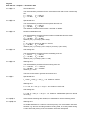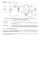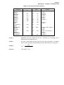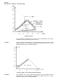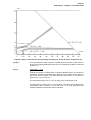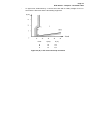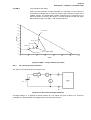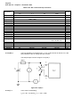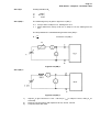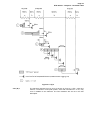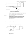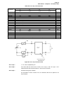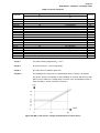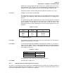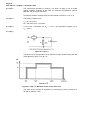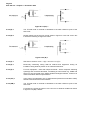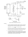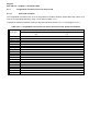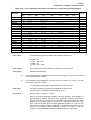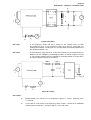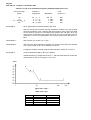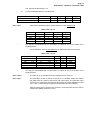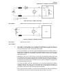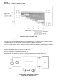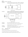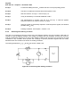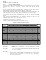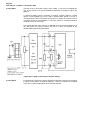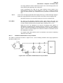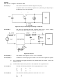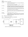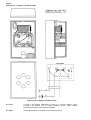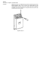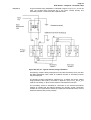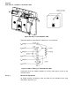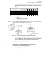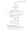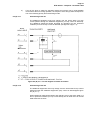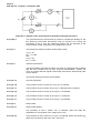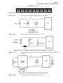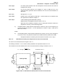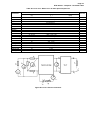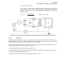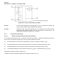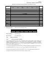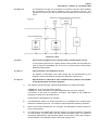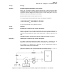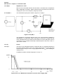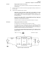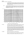
1
EUROPEAN TELECOMMUNICATION STANDARD December 1994 Source: ETSI TC-TE Reference: RE/TE 04-16 ETS 300 001 Second Edition ICS: 33.040.20 Key words: PSTN, Access, TE, General Attachments to the Public Switched Telephone Network (PSTN); General technical requirements for equipment connected to an analogue subscriber interface in the PSTN Chapter 1: General ETSI European Telecommunications Standards Institute New presentation - see History box ETSI Secretariat Postal address: F-06921 Sophia Antipolis CEDEX - FRANCE Office address: 650 Route des Lucioles - Sophia Antipolis - Valbonne - FRANCE X.400: c=fr, a=atlas, p=etsi, s=secretariat - Internet: [email protected] Tel.: +33 92 94 42 00 - Fax: +33 93 65 47 16 Copyright Notification: No part may be reproduced except as authorized by written permission. The copyright and the foregoing restriction extend to reproduction in all media. © European Telecommunications Standards Institute 1994. All rights reserved. Page 2 ETS 300 001 - Chapter 1 : December 1994 Whilst every care has been taken in the preparation and publication of this document, errors in content, typographical or otherwise, may occur. If you have comments concerning its accuracy, please write to "ETSI Editing and Standards Approval Dept." at the address shown on the title page. Page 3 ETS 300 001 - Chapter 1 : December 1994 Contents Foreword .......................................................................................................................................................5 1 General................................................................................................................................................7 1.1 Introduction ..........................................................................................................................7 1.1.1 Foreword .........................................................................................................7 1.1.2 NETs ...............................................................................................................7 1.1.3 Types of NET ..................................................................................................8 1.1.4 NET 4 ..............................................................................................................8 1.2 Scope...................................................................................................................................9 1.3 Method of use ....................................................................................................................11 1.3.1 Structure of the ETS......................................................................................11 1.3.2 Use of requirements and tests ......................................................................11 1.4 Definitions of terms used in this ETS.................................................................................11 1.4.1 Local subscriber line (analogue) ...................................................................11 1.4.2 Public Switched Telephone Network (PSTN)................................................11 1.4.3 PSTN connection point..................................................................................12 1.4.4 Terminal equipment ......................................................................................12 1.4.4.1 General definitions...............................................................12 1.4.4.2 Types of TE .........................................................................14 1.4.4.3 Reference model of a TE.....................................................16 1.4.4.4 Testing point ........................................................................16 1.4.5 States or conditions of TE .............................................................................18 1.4.5.1 Quiescent or idle state or condition .....................................18 1.4.5.2 Ringing state or condition ....................................................19 1.4.5.3 Loop state or condition ........................................................19 1.4.5.4 Dialling or signalling state or condition ................................19 1.4.5.5 Register recall state or condition .........................................19 1.4.6 Line terminals ................................................................................................19 1.4.7 Speech band .................................................................................................19 1.5 DC feeding arrangements..................................................................................................20 1.5.1 Requirement values for feeding conditions ...................................................21 1.5.2 Test values for feeding conditions.................................................................25 1.6 Test parameters.................................................................................................................27 1.6.1 Environmental conditions ..............................................................................27 1.6.2 Tolerances of components used for testing ..................................................27 1.6.3 Test equipment accuracy ..............................................................................27 1.6.4 Test equipment resolution .............................................................................27 1.6.5 Measurement values .....................................................................................28 1.6.6 TE connection ...............................................................................................28 1.6.6.1 Series-connected TEs .........................................................28 1.6.6.2 Additional wires....................................................................28 1.7 Summary of network tones and signals (informative)........................................................28 1.7.1 Dial tone ........................................................................................................28 1.7.2 Ringing tone ..................................................................................................30 1.7.3 Busy tone.......................................................................................................32 1.7.4 Congestion tone ............................................................................................33 1.7.5 Special information tone(s)............................................................................35 1.7.6 Call in progress tone .....................................................................................38 1.7.7 Tones for other purposes ..............................................................................39 1.7.8 Frequencies for pulse metering.....................................................................46 1.7.9 Ringing signal ................................................................................................49 1.8 Abbreviations .....................................................................................................................52 1.9 National designators ..........................................................................................................53 1.10 Symbols .............................................................................................................................54 1.11 Summary of references .....................................................................................................56 History..........................................................................................................................................................57 Page 4 ETS 300 001 - Chapter 1 : December 1994 Blank Page Page 5 ETS 300 001 - Chapter 1 : December 1994 Foreword Chapter 1 of this European Telecommunication Standard (ETS) has been produced by the Terminal Equipment (TE) Technical Committee of the European Telecommunications Standards Institute (ETSI). The text of this ETS may be utilized, wholly or in part, for the establishment of NET 4. For historical purposes, this ETS was drafted in the form of a NET. However, the terms NET or NET 4 in this document should be read as ETS or ETS 300 001 respectively. This ETS comprises ten chapters: "Attachments to Public Switched Telephone Network (PSTN); General technical requirements for equipment connected to an analogue subscriber interface in the PSTN". Chapter 1 Chapter 2 Chapter 3 Chapter 4 Chapter 5 Chapter 6 Chapter 7 Chapter 8 Chapter 9 Chapter 10 - General DC characteristics Ringing signal characteristics Transmission characteristics Calling functions Answering function Power failure Connection methods Special functions Additional unclassified requirements This is the first chapter providing, among other information, the scope of this ETS, definitions, symbols and abbreviations, an explanation of the structure of the ETS and its method of use. This ETS contains requirements and associated compliance tests. Each compliance test has been assigned a section number which is identical to that of the related requirement and has been given the prefix "A". The requirements and their associated compliance tests are grouped together in the main body of this ETS. National variations to each requirement and test, which may be particular to an Administration, are given as additional text within the body of each requirement or test. The national designations used are given in section 1.9 of this chapter. Section 1.3 provides further details on the structure and how to use this ETS. Page 6 ETS 300 001 - Chapter 1 : December 1994 Blank page Page 7 ETS 300 001 - Chapter 1 : December 1994 1 1.1 1.1.1 General Introduction Foreword It is recognised, in the field of telecommunications within Europe, that there is a need to create common European standards for telecommunication equipment. Such harmonisation would, among other things, facilitate co-operation between telecommunication equipment manufacturers and public telecommunication network operators, create a marketplace which naturally transcends that of national frontiers, enhance the efficiency of business and other communications across Europe to bring economic benefits, and help translate the vision of a united Europe into a working reality. In 1985, an initiative by the Conference of European Posts and Telecommunications Administrations (CEPT) resulted in the drafting of a Memorandum of Understanding (MoU) agreeing to the mutual recognition of results of tests of conformity to a technical specification which would be known as a Norme Européenne de Telecommunication (or NET). The signatories of the MOU represent the telecommunications administrations of most countries in Western Europe, including EEC and EFTA administrations. In 1986, European Community Council Directive 86/361/EEC laid down the principles of the initial stage of the mutual recognition of type approval for telecommunications Terminal Equipment (TE). The Directive imposes the obligation on EC Member States to implement the recognition of tests to common conformity specifications. 1.1.2 NETs The guiding principals under which a NET is written are the need to ensure that essential requirements are met. These include: - user safety, insofar as this requirement is not covered by other legal instruments (e.g. Directive 73/23/EEC); safety of employees of the public telecommunication network operators, insofar as this requirement is not covered by other legal instruments (e.g. Directive 73/23/EEC); protection of public telecommunication networks from harm; interworking of TE, in justified cases. Each NET constitutes part of a series of NETs prepared in response to the MOU and the EC Directive 86/361. A NET details the requirements, and a specification of interface tests for conformance to those requirements, which a defined type of telecommunication TE is required to satisfy in order to obtain authorisation for connection of the equipment to a defined European Telecommunications Network. The NET also includes, where appropriate, requirements made necessary in a given State by historical network peculiarities. The existence of a NET will make it possible for an accredited laboratory in a country whose administration has signed the MOU, to carry out tests, specified in the NET, on TE submitted to it, and to issue a test report. On the basis of the report, a competent body may then issue a certificate of conformity to the NET. There may of course be cases where the laboratory itself is the competent certification authority. This certificate is then recognised as valid in all other signatory countries, avoiding the need for the equipment to have to undergo the same tests, over and over again, each time approval is applied for in any of those countries. The common reference point which a NET represents thus offers the opportunity of substantially reducing the complexity, length and cost of approval formalities. The operators of public networks are required to make reference to relevant NETs in public supply contracts. Manufacturers are thereby enabled to compete on a more equal technical basis in the supply of terminal equipment covered by NETs. Page 8 ETS 300 001 - Chapter 1 : December 1994 1.1.3 Types of NET The majority of NETs fall into one of two categories; access NETs and terminal NETs as described below; a) Access NET Details of the technical characteristics (electrical, mechanical and access control protocols), to be offered by TE at the interface to a specific public telecommunications network are covered in an access NET. The objective of an access NET is to ensure no disturbance occurs to the network and to ensure interworking between network and TE so that calls can be routed successfully through the network (but without any guarantee of terminal to terminal operation). Indeed, since an access NET may have to serve a number of terminal NETs and applications which have not even been envisaged at present, it is important for the content not to include anything which is particular to a specific terminal or otherwise inhibiting to new developments. b) Terminal NET The objective of a terminal NET is to ensure the end-to-end compatibility of a defined telecommunication service. The terminal NET should indicate any requirement which must be added to the corresponding access NET(s) to ensure end-to-end communication. 1.1.4 NET 4 ETSI has adopted this approach in the generation of NETs, but labelled as follows: a) b) c) Aspect 1 - General requirements; Aspect 2 - Access requirements; Aspect 3 - TE requirements. This document is a candidate for adoption as an access NET and is to be used for type approval according to the scope stated in section 1.2. TE submitted for type approval is subject to Aspect 1 requirements in every case and, in addition to other relevant requirements e.g. NETs, international or national specifications. Such additional requirements are not contained in this document. Aspect 3 NETs or other national standards which are relevant to a given type of TE meeting the requirements of this NET shall be in addition to, and refer to the requirements in this NET and shall not modify the requirements in this access NET. 1.1.4 (D) 1 In accordance with the three level approach of EG and ETSI, all TEs have to fulfil in addition to the requirements stated in this document the following Aspect 1 requirements: - electrical safety; climatic environment; EMC. As long as there are no European recommendations for electrical safety, climate and EMC, the relevant enclosures of the national specifications 1 TR 2, Part 1 are applicable. Page 9 ETS 300 001 - Chapter 1 : December 1994 1.2 Scope This Access ETS specifies the technical requirements (electrical, mechanical and method of signalling) and their associated compliance tests to be met by all TE at each of its ports provided for connection to the Public Switched Telephone Network (PSTN). This connection is effected at a standard analogue interface. This interface is characterised by a two-wire derived presentation using dc loop seizure and clear and low-frequency ac ringing signals below the speech passband. These requirements and associated compliance tests form the definition of the standard analogue PSTN access (Aspect 2) in each of the participating Administrations. It is recognised that for historical reasons requirements and their associated compliance tests may include values particular to each Administration's network. These requirements reflect existing standards. This access ETS does not necessarily contain all the requirements which a specific type of TE shall meet in order to gain type approval for attachment to the relevant PSTN attachment point. 1.2 (DK) 1 This document does not form the type approval requirements for those equipments that are part of PABX or other complex installations connected to the PSTN. For these types of installations, including their associated (series- or parallel connected) equipment to the PSTN, DK national requirements apply. In every case, reference shall be made to the DK Approval Authority in order to determine the totality of applicable requirements and associated tests. 1.2 (SF) 1 This document does not form the type approval requirements for TE that contain call routing and switching functions except very small PBXs or key systems with 1 or 2 trunk lines. For TE with more trunk lines, the national standards apply. 1.2 (F) 1 The national values contained in the current issue of this NET are not applicable to the standard analogue interface used for the connection to the PSTN when connecting a complex installation. For these types of installation, connection to the PSTN is covered by: - I-ETSs 300 003 and 300 004 for transmission characteristics of digital PABXs; national standards for other characteristics of digital PABXs and for other complex installations, until a new enhancement of this ETS will be available. Complex installations are hereby understood as equipment: or or 1.2 (D) 1 able to interconnect PSTN accesses (e.g. call diverting devices); able to broadcast the same information to several PSTN accesses at the same time. This document basically applies to all TE intended for linking to customer accesses with analogue interconnection points. For PBXs, besides the interface requirements set out in this document, relevant provisions are contained in the: - 1.2 (D) 2 including switching capability to interconnect at least one PSTN access with at least two other ports (e.g. PBXs); approval specifications for PABXs and telecommunications systems, KNr.: 651 500 800-0 (catalogue number). This document is applicable for PABXs and telecommunications systems in which the a/b input wires are switched galvanically to the extension lines. Technical equipment intended for connection to these PABXs via user accesses for permanent services are subject to other regulations. This document does not apply for TEs connected to public call offices. Page 10 ETS 300 001 - Chapter 1 : December 1994 1.2 (D) 3 This guideline does not apply to TE intended to be connected to: - - user access for broadcast services; radiopaging accesses; special telephone accesses; a) mobile radiotelephone accesses; b) accesses for maritime mobile communication; c) Rhine radiotelephone accesses; d) emergency telephone accesses for the police and fire brigade; e) public emergency call boxes; telephone accesses with Impulskennzeichengabe (IKZ); telephone accesses with Gleichstromkennzeichengabe (GKZ); accesses for Group 1 fixed connections (leased lines); accesses for the warning and alarm service. For these accesses special regulations apply. 1.2 (D) 4 In view of the reunification of the FRG and the GDR, the requirements imposed by the FRG in this document possibly have to be supplemented with the particularities of the GDR-specific network requirements. Pending corresponding amendment of this document, the document containing these particularities can be obtained from the approval authority and may be ordered from there. 1.2 (I) 1 This document does not form the type approval requirements for those TE that contain call routing or switching functions. In these cases Italian national requirements apply. In every case, reference must be made to the Italian Approval Authority in order to determine the totality of applicable requirements and associated tests. 1.2 (NL) 1 This document does not contain the type approval requirements for those TE that contain call routing and switching functions. In these cases Dutch national requirements apply and reference must be made to the Dutch Approval Authority in order to determine the totality of applicable requirements and associated tests. 1.2 (N) 1 This document does not contain the type approval requirements for those equipment that includes call routing and switching functions, and which provides local dc loop current on the extension side of the equipment. In these cases the Norwegian national requirements apply. 1.2 (S) 1 This standard shall not form the type approval requirements for user classes of equipment that are characterised as providing: - multiple lines to the PSTN; multiple ports for separately identifiable terminal equipment; switching and routing functions; and the capability of providing additional telecommunication services at these ports not provided by the PSTN. Accordingly, this document is not applicable for PBXs and other private telecommunication networks nodal components. In these cases the Swedish national requirements apply. 1.2 (GB) 1 This document does not form the type approval requirements for equipment that contain certain call routing or certain switching functions, in these cases UK national requirements apply and reference must be made to the UK Approval Authority in order to determine the totality of applicable requirements and associated tests. Page 11 ETS 300 001 - Chapter 1 : December 1994 1.3 1.3.1 Method of use Structure of the ETS This ETS contains requirements and associated compliance tests. Each compliance test has been assigned a section number which is the same as the related requirement and has, in addition, a prefix "A". Thus the requirements and their associated compliance tests are grouped together in the main body of the document. Where applicable, each requirement and associated compliance test have harmonised text which includes parameters to which each Administration may assign its own values. In these cases, parameter values are set out in accompanying tables. National variations to each requirement and test which may be particular to a single Administration are set out as additional text within the body of each requirement or test. These are designated nationally according to the convention set out in section 1.9 and are referenced in the "remarks" column of relevant tables. This ETS includes a number of Chapters, arranged according to general technical content; Chapter 1 includes introductory information of a general nature, definitions and abbreviations. Chapter 10 includes technically unclassified additional national requirements and tests particular to various Administrations. It may therefore be necessary, in order to determine the total requirement and compliance test in any given case, to refer to the harmonised text and its national variations as well as to the relevant contents in Chapter 10. 1.3.2 Use of requirements and tests Each of the requirements in the common text of this document is a harmonised text. The use of each requirement by each Administration is determined by parameter values shown in the requirement table(s) and may be qualified further by remarks. These are set out in the requirement table(s). It is common to find that certain requirements are to be met over ranges of parameter values; for example, return loss values might be required to be met over two independent ranges of frequency and of loop current. In such cases, compliance may be determined by testing at a limited number of parameter test values within these ranges. Such cases are clearly set out. TE which, on the basis of testing outlined in this document, appears to comply with a requirement but which subsequently is found to be noncompliant at an untested point within the range must be considered according to the relevant type approval procedures under which this document is used. 1.4 Definitions of terms used in this ETS The following terms are given particular meaning within this ETS. Other technical terms not specifically mentioned are to be taken according to their normally accepted meaning. 1.4.1 Local subscriber line (analogue) An analogue subscriber line is part of a local telephone network and is traditionally metallically connected to the analogue interface of an exchange port by means of two wires (normally termed the a-wire and the b-wire) and to which an unique telephone network address has been assigned (telephone number). NOTE: 1.4.2 This definition does not exclude standard analogue interfaces of the PSTN where a unique telephone network address is assigned to a number of such separate physical presentations. Public Switched Telephone Network (PSTN) A generally used term for the nation-wide public telephone network comprising interconnected telephone exchanges capable of switching telephone calls between telephones connected to the network (exchanges). Page 12 ETS 300 001 - Chapter 1 : December 1994 1.4.3 PSTN connection point The point where the local subscriber line (analogue) is terminated, the PSTN standard analogue interface is presented and the TE is connected. Reference is made to figure 1.4.4.3. a) Leads a1 and b1 are provided for connection to the PSTN. b) Leads a2 and b2 (if they are provided) are intended for the connection of this TE in series with other TEs. c) Additional leads for instance n1 (if provided) are intended for auxiliary connections, to be defined by the National Administrations' Network Termination Schedules (Chapter 8). d) Additional leads for instance n2 (if provided) are intended for optional connections, to other TEs, to be defined in Chapter 8. e) Lead "e" (if provided) is intended for connection to signal earth. f) Figure 1.4.4.3 does not indicate that TEs may have other interfaces. These interfaces are not described in this document. 1.4.3 (E) 1 Common reference terminal The common reference terminal is defined as the terminal or lead provided for connection to a common reference potential, for the functional purpose of receiving longitudinal 50 Hz metering pulses. In the Spanish contribution (E) this terminal or lead is normally called "REF", and it may either be connected internally to the earth terminal or lead "e", when it exists, or not. 1.4.4 1.4.4.1 Terminal equipment General definitions Terminal equipment is defined as an equipment which is intended to be connected to a termination point of PSTN (PSTN connection point: PSTN CP). One-port TE is defined as TE with wires or leads intended solely for connection to a PSTN CP (see figure 1.4.4.1.a). Figure 1.4.4.1.a: One-port TE Series-connected TE is defined as TE intended to be attached to a PSTN CP and which in addition provides a second connection point to which a second TE may be attached so as to permit this second TE to be excited solely by loop current wholly derived from the PSTN connection (see figure 1.4.4.1.b). Page 13 ETS 300 001 - Chapter 1 : December 1994 Figure 1.4.4.1.b: Series-connected TE NOTE: Two or more TE can be connected to the PSTN CP in parallel (see figure 1.4.4.1.c). Figure 1.4.4.1.c: Parallel connected TE 1.4.4.1 (D) 1 For TEs with telephony functions in Germany direct parallel connection is not permitted. Reference is made to Chapter 8. 1.4.4.1 (D) 2 In the German contribution (D), in some places the term "additional equipment" which is a special group of series-connected TEs is used instead of "seriesconnected TE". Special reference is made to section 8.3 (D). 1.4.4.1 (E) 1 (This remark relates to series-connected TEs). PROVISION: Network compatibility cannot be expected if several series TEs are simultaneously connected in series to the same line. NOTE: In the Spanish contribution (E), the additional requirements for series TEs have the word "series" included in brackets in the requirement heading. 1.4.4.1 (E) 2 Associated TE Associated TE is defined as a TE which is approved for connection to the network. This name is normally used, in the Spanish contribution (E), to designate a TE which is connected to the line output terminals of a seriesconnected TE. 1.4.4.1 (E) 3 Multiline TE Multiline TE is defined as a TE which is able to be connected to either more than one PSTN connection point, or to a multiline PSTN CP. Page 14 ETS 300 001 - Chapter 1 : December 1994 NOTE: 1.4.4.1 (GB) 1 In the Spanish contribution (E), the additional requirements for multiline TEs have the word "multiline" included between brackets in the requirement heading. Series-connected TE Series-connected TE can be of two types: i) those for which the electrical characteristics have in every case values that represent the maximum impairment that may be introduced between the main TE and the PSTN connection point (CP) of a complete system; consequently, if the whole of the allowance for one or more of the parameters is consumed by a series-connected TE then no other equipment or leads consuming the same characteristic will be permitted within a system containing such series-connected TE; ii) those for which the electrical characteristics have sufficient margin against the maximum allowable impairments such that more than one such series-connected TE can be connected within a system; the number of items of TE that may be seriesconnected is determined by the Series Equivalent Number (SEN), which may have a value between 0,3 and 1. Thus SEN is a number that represents the portion of the maximum allowable impairment which is taken up by a series-connected TE and may be used to calculate the composition of a TE system connected to the PSTN; this number is determined by the larger of two quantities representing the dc resistance and the insertion loss (see 4.3 (GB) 1). 1.4.4.2 Types of TE TE can generally be categorised into one or more of the following types: Type 1: One-port TE capable of holding the loop condition by itself (e.g. telephone set), see figure 1.4.4.2.a. Figure 1.4.4.2.a: One-port TE (loop holding) Type 2: One-port TE not capable of holding the loop condition by itself (e.g. ringing detector) see figure 1.4.4.2.b. Figure 1.4.4.2.b: One-port TE (non-loop holding) Type 3: A series-connected TE through which the loop condition to another TE can be maintained, but is capable of holding the loop condition by itself. It is possible for this type to have two arrangements: Page 15 ETS 300 001 - Chapter 1 : December 1994 Type 3 (I): The loop is held but the output port is disconnected (e.g. modem), see figure 1.4.4.2.c. Figure 1.4.4.2.c: Series-connected TE (loop holding, output disconnected) Type 3 (II): The loop is held and the output port remains connected (e.g. answering machine), see figure 1.4.4.2.d. Figure 1.4.4.2.d: Series-connected TE (loop holding, output connected) Type 4: A series-connected TE through which the loop condition to another TE can be maintained, but is not capable of holding the loop condition by itself (e.g. monitoring device), see figure 1.4.4.2.e. Figure 1.4.4.2.e: Series-connected TE (non-loop holding) Page 16 ETS 300 001 - Chapter 1 : December 1994 1.4.4.3 Reference model of a TE A reference model of a TE is shown in figure 1.4.4.3. Figure 1.4.4.3: TE reference model 1.4.4.3 (B) 1 1.4.4.4 The second plug (or socket) shown in figure 1.4.4.3 may be combined with the first plug as a standard intermediate plug (see Chapter 8). Testing point Testing points are defined in table 1.4.4.4. in conjunction with figure 1.4.4.4 (see also figure 1.4.4.3). Figure 1.4.4.4: Definition of testing point Page 17 ETS 300 001 - Chapter 1 : December 1994 Table 1.4.4.4: Testing points TESTING POINT Remarks COUNTRY TP0 Austria Belgium Cyprus Denmark Finland France Germany Greece Iceland Ireland Italy Luxembourg Malta Netherlands Norway Portugal Spain Sweden Switzerland U. Kingdom TP1 X X X X X X X X X TP2 X X X X X X X TP5 TP6 yes yes yes yes yes X X X X X X X X yes yes X X yes yes X X X X X X X X X X X X X X X X X X X X X X TP4 X X X X TP3 X X X X X yes yes yes yes yes X 1.4.4.4 (A) 1 Testing point TP1 shall be used if cross-talk is possible to other circuits. 1.4.4.4 (B) 1 In case of multiline TE, the testing points may be TP2 (or TP3) and TP5 (or TP4). 1.4.4.4 (CY) 1 TP3 shall only be used in case the cord is removable. 1.4.4.4 (DK) 1 If the TE is provided with a cord, the type approval shall include plug and cord. If the TE is provided with a permanent connection (e.g. screws), the testing shall be performed using TP3 and TP4, respectively. 1.4.4.4 (SF) 1 If the TE is provided with a cord, the type approval shall include the plug and cord (testing point TP1). If the TE is provided with a permanent connection (e.g. screws), the testing shall be performed using TP3. In case of a series-connected TE testing point TP4 or TP6 is used, depending on whether the series-connected TE has plug and cord or a permanent connection. 1.4.4.4 (D) 1 If the TE is provided with a cord, the type approval shall include the plug and cord. If the TE is provided with a permanent connection (e.g. screws), the testing shall be performed using TP3. 1.4.4.4 (GR) 1 If the TE is provided with a cord, the type approval shall include the plug and cord. If the TE is provided with a permanent connection (e.g. screws), the testing shall be performed using TP3 and TP4 if it exists. 1.4.4.4 (IRL) 1 If the TE is provided with a cord, the type approval shall include the plug and cord. If the TE is provided with a permanent connection (e.g. screws), the testing shall be performed using TP3. The test points for series-connected equipment where applicable on port a2b2 shall be the second plug or socket if supplied with the TE, or else TP4. 1.4.4.4 (I) 1 If the TE is provided with a cord, the type approval shall include the plug and cord. If the TE is provided with a permanent connection (e.g. screws), the testing shall be performed using TP3 and TP4 if it exists. Page 18 ETS 300 001 - Chapter 1 : December 1994 1.4.4.4 (N) 1 If the TE is provided with a cord, the type approval shall include the plug and cord. If the TE is provided with a permanent connection (e.g. screws), the testing shall be performed using TP3. 1.4.4.4 (N) 2 If the TE is provided with a cord, TP6 is used. If the TE is provided with a permanent connection, the TP4 is used. 1.4.4.4 (P) 1 TE provided with cord(s) and plug(s) shall be tested with the related socket(s). So, testing point TP0 shall be used. 1.4.4.4 (P) 2 Testing point TP2 shall be used for TE provided with a cord or a cord and a connection box. 1.4.4.4 (P) 3 Testing point TP2 shall be used for TE provided with a cord, a cord and a connection box or a cord and a socket. 1.4.4.4 (P) 4 Testing points TP3 and TP4 shall be used for TE provided with no cords. 1.4.4.4 (E) 1 The cord which is shown in figure 1.4.4.4 cannot be a constitutive part of the TEUT, but the plug shall be. NOTE: When the TEUT is provided with an earth (or earth protection) terminal or lead, then the testing point 3 (TP3) (or testing point TP4) is used in certain test arrangements together with the accessible parts. 1.4.4.4 (CH) 1 1.4.5 If the TE is provided with a cord, the type approval shall include the plug and cord. If the TE is provided with a permanent connection (e.g. screws), the testing shall be performed using TP3. States or conditions of TE The states below are always states of TE. 1.4.5.1 Quiescent or idle state or condition Quiescent or idle state or condition is defined as an electrical condition into which the TE, when connected to the network, is placed such that it draws minimum current and does not activate the exchange. In this case some equipment connected in series to other TE may be operating (e.g. recording apparatus with a high ohmic resistance). 1.4.5.1 (E) 1 When the TE is in quiescent or idle state or condition, it shall not be capable of sending nor receiving speech-band information to or from the network. (See also the paragraph "a" in section 1.4.5.1 (E) 2, and the note in section 1.4.5.3 (E) 1). 1.4.5.1 (E) 2 High impedance state or condition High impedance state or condition is defined as an electrical condition into which the TE, when connected to the network, is placed such that it is a) potentially capable of sending or receiving speech-band information or other classes of signals to or from the network; and b) supposed to be simultaneously when another TE, which is connected to the same termination point of the network, is in loop condition or dialling condition or register recall condition. It shall be noted that this condition may be exclusively invoked during the situation defined here. Page 19 ETS 300 001 - Chapter 1 : December 1994 1.4.5.2 Ringing state or condition Ringing state or condition is defined as a quiescent or idle state or condition into which ringing signal is applied. 1.4.5.3 Loop state or condition Loop state or condition is defined as an electrical condition into which, when connected to the network, TE is placed such that it draws enough dc current to be capable of activating the exchange. 1.4.5.3 (E) 1 PROVISION: In some Spanish requirements, when no specific mention to the high impedance condition is made, and the term loop condition is used just in the opposite meaning of the term quiescent condition, the term loop condition is also used simultaneously with the sense of high impedance condition (see section 1.4.5.1 (E) 2). NOTE: Usually, the TE in loop condition is potentially capable of sending or receiving speechband information to or from the network. 1.4.5.4 Dialling or signalling state or condition Dialling or signalling state or condition of a TE is defined as a condition into which the TE, when connected to the network, is placed such that it passes to the network break pulses or MFPB signals. 1.4.5.5 Register recall state or condition Register recall state or condition of a TE is defined as a condition into which the TE, when connected to the network, is placed such that it passes to the network a register recall signal. 1.4.6 Line terminals The term "line terminals" is used throughout the NET as an abbreviated form of "terminals or leads provided for connection to the PSTN CP". 1.4.6 (E) 1 The term "line terminals" is also used instead of line input terminals in series TEs. They are normally called "a1" and "b1" ("a1,i", "b1,i", for multiline TEs). 1.4.6 (E) 2 Line input terminals Line input terminals are defined as the two terminals of the port provided for connection to the network in series TEs. They are normally called "a1" and "b1" ("a1,i", "b1,i", for multiline TEs). 1.4.6 (E) 3 Line output terminals Line output terminals are defined as the two terminals of the port which provides a termination point for the connection of one associated TE (see section 1.4.4.1 (E) 2) in series TEs. They are normally called "a2" and "b2" ("a2,i", "b2,i", for multiline TEs). 1.4.7 Speech band The speech band is defined as the 300 - 3 400 Hz frequency band. Page 20 ETS 300 001 - Chapter 1 : December 1994 1.5 DC feeding arrangements The dc feeding arrangements differ for each Administration but generally are of a similar nature to that given in the Idealised Feeding Bridge described in figure 1.5. The feeding resistance Rf includes the resistance of the inductor Lf. Figure 1.5: Idealised feeding bridge circuit The standard values of inductors Lf and capacitors Cf for each Administration are included within this section (see table 1.5). Table 1.5: Idealised feeding bridge values REQUIREMENT VALUES COUNTRY Austria Belgium Cyprus Denmark Finland France Germany Greece Iceland Ireland Italy Luxembourg Malta Netherlands Norway Portugal Spain Sweden Switzerland U. Kingdom 1.5 (DK) 1 Cf (µF) ≥ 47 20 4 ≥2 2 ± 2% 100 ± 5% ≥ 47 20 ≥2 470 2 ≥ 47 20 ≥ 10 ≥ 50 ≥ 20 ≥ 2,2 ≥ 47 ≥ 400 Lf (H) ≥5 5 2 ≥2 ≥2 5 ± 10% ≥5 5 ≥2 10 ≥1 ≥5 2 ≥5 ≥ 2,5 ≥5 ≥2 ≥5 ≥ 10 Requirement values according to national test circuits. Remarks yes yes yes Page 21 ETS 300 001 - Chapter 1 : December 1994 1.5 (I)1 Cf = 47 µF; Lf = 5 H to perform type approval tests in section A.4.1.2. 1.5 (E) 1 In some test procedures other feeding arrangements or other values may be used. In all cases in which a feeding bridge is specified, the values of inductors (Lf) and capacitors (Cf) shall be met at all frequencies of measurement, and the circuit diagram of the feeding bridge used may have additional components to meet this requirement. For this reason the diagram shown in figure 1.5 is considered to be an idealised representation of the circuit at the frequency or frequencies of measurement. In all cases in which a dc voltage source or an ac signal generator is specified, it is understood that the values of the external associated components absorb the values of the source/generator output resistance. When a dc voltage source is connected in series with an ac signal generator, both they shall be coupled in such a manner that the magnitude of the dc voltage source impedance shall be near 0 Ω, at the frequencies of testing. 1.5 (E) 2 Mains test power source When the Terminal Equipment Under Test (TEUT) is intended to be connected to the mains, then a) the voltage of the mains test power source shall be within ± 5% of any of the declared nominal mains voltages for which the TE is prepared; and b) 1.5 (E) 3 the frequency of the mains test power source shall be within ± 1 Hz of the nominal frequency of 50 Hz. Other test power sources When the TEUT is intended to be powered from power sources other than the network and/or the mains, the voltage of the test power sources shall be within ± 5% of the declared nominal voltages. 1.5.1 Requirement values for feeding conditions The range of ∆Vf, ∆Rf and ∆If (where applicable) which should be applied to the feeding bridge circuit in order to represent the local exchange network and subscribers line of each Administration are given in table 1.5.1. All requirements should be fulfilled within all ranges specified in table 1.5.1, except otherwise specified. Page 22 ETS 300 001 - Chapter 1 : December 1994 Table 1.5.1: Requirement values for feeding conditions ∆Vf (V) COUNTRY Austria Belgium Cyprus Denmark Finland France Germany Greece Iceland Ireland Italy Luxembourg Malta Netherlands Norway Portugal Spain Sweden Switzerland U. Kingdom REQUIREMENT VALUES ∆Rf (Ω) 44,5 - 53 43 - 53 44 - 56 44 - 58 46 - 54 89 - 104 60 44 - 66 43 - 56 48 44 - 52 60 360 - 1 725 400 - 1 740 500 - 2 400 800 - 1 710 300 - 1 400 1 400 - 2 960 1 000 - 3 500 42 - 66 24 60 45 - 55 48 800 - 2 140 460 - 1 000 (1 200) 460 - 3 100 (3 500) 300 - 5 500 500 - 2 200 43 - 57 50 2 200 - 600 ≥ 400 800 - 2 400 0 - 5 000 720 - 5 000 ∆If (mA) 19 - 60 Remarks yes 20 - 100 ≤ Imax. yes 25 - 60 yes 20 - 80 14 - 70 20 - 100 14 - 60 16 - 80 yes yes not applicable yes yes yes 0 - 125 ∆Vf in idle condition of the PSTN line circuit: 15...64 V ∆If in transient condition to go from the idle to the loop condition of PSTN line circuit: 1...60 mA. 1.5.1 (A) 1 ∆Vf in feeding condition of PSTN line circuit: 50...60 V ∆If in feeding condition of PSTN line circuit: 19...60 mA. In the Austrian network a limitation of the feeding current to a value of "n" mA for new exchanges is under study. Transient time of the PSTN line circuit to go from idle to loop condition: ≤ 40 ms. 56 V 500 Ω + RTEUT 1.5.1 (DK) 1 Ιmax. = 1.5.1 (F) 1 The values given in table 1.5.1 are related to the conversation state, case a) referring to normal feeding and case b) to overfeeding. The case c) is used for series-connected TE with normal feeding as well as with overfeeding. The feeding conditions in other states are as follows: State Quiescent Ringing: Dialling: polarised non-polarised decadic MFPB(DTMF) Howler Normal feeding Vf (V) Rf (Ω) 45 - 54 300 - 3 600 45 - 54 300 - 3 600 42 - 54 360 - 1 740 45 - 54 300 - 1 845 46 - 54 300 - 1 450 52 - 54 300 - 8 225 Overfeeding Vf (V) Rf (Ω) 86 - 104 1 400 - 3 000 86 - 104 1 400 - 3 000 90 - 106 1 360 - 2 900 86 - 104 1 400 - 3 350 89 - 104 1 400 - 2 960 82 - 104 1 400 - 5 225 Page 23 ETS 300 001 - Chapter 1 : December 1994 For each requirement, the ranges of feeding values Vf, Rf and If (where applicable) for which the requirement shall be met, are given in the relevant table. NOTE: 1.5.1 (NL) 1 The maximum value of PSTN feeding voltage Vf can be 56 V instead of 54 V for at most 24 hours per month. At any place throughout NET 4 where feeding voltage and feeding resistance is stated as ∆Vf = 42 - 66 V and ∆Rf = 800 - 2 140 Ω has to be read in a way that the highest voltage (66 V) belongs to the lowest resistance (800 Ω) and the lowest voltage (42 V) belongs to the highest resistance (2 140 Ω). The nominal value of the voltage (48 V) belongs to a resistance of 1 130 Ω. The loop current is not regulated but is depending on the feeding condition, the loop resistance and the dc resistance of the TE. The value of the loop current is between about 16 mA and about 80 mA. 1.5.1 (N) 1 The requirements given in the Norwegian regulations shall be complied with in loop condition for current values derived from a feeding voltage (Vf) of 60 V, a feeding resistance (Rf) between 460 and 3 100 Ω, and the dc resistance of the TE. In addition, the equipment shall function properly for Rf values up to 3 500 Ω. The maximum line current is defined as the current flowing through the TEUT when Rf = 460 Ω. For some characteristics, specific requirements are given for line current values between 15 and maximum line current. 1.5.1 (E) 1 In some requirements other values than those indicated in this section may be specified. In general, six cases (I to VI) of specifying dc feeding excitations could happen, as it is indicated in table 1.5.1 (E) 1, with the following definitions: Case I For situations where no feeding bridge is used and a dc feeding excitation is needed, but its concrete values do not affect results. Case II For resistance in loop condition and make resistance during decadic dialling. No feeding bridge is used. NOTE: The maximum loop current achieved during these situations may be lower than the higher values quoted in tables 1.5.1 (E) 1 and 1.5.2 (E) 1 because of the current limitations imposed by the TE resistance. Case III For other decadic dialling and register recall situations. No feeding bridge is used. Case IV For other dc situations. No feeding bridge is used. Case V For dialling with DTMF signals and metering pulses reception. A feeding bridge is used (see sections 1.5 and 1.5 (E) 1). Case VI For other ac situations. A feeding bridge is used (see sections 1.5 and 1.5 (E) 1). Page 24 ETS 300 001 - Chapter 1 : December 1994 Table 1.5.1 (E) 1: Requirement values for feeding conditions Case If (mA) Vf (V) I II III IV V VI n.s. 18,5 - 100 n.i. 43 - 56 n.s. 48 NOTES: Rf (Ω) n.i. 300 - 2 300 500 - 2 200 500 - 1 700 500 - 2 200 500 - 1 700 n.s. = not specified n.i. = not indicated 1.5.1 (S) 1 See remark 1.5.2 (S) 1. 1.5.1 (CH) 1 General comments on supply arrangements: Exchange supply voltages Vf: Nominal 48 V, limits: 43 and 57 V; 60 V for 5 minutes per month. Nominal 60 V, limits: 56 and 66 V; 75 V for 5 minutes per month. In the idle state certain lines or supplementary devices (e.g. line concentrators, alarm equipment) supply 24 V or 12 V dc. dc resistance of the subscriber line: RL = 0 to 2 x 350 Ω (for PABXs: 0 to 2 x 250 Ω) Feeding characteristics of exchanges: Table 1.5.1 (CH) 1 RS (Ω) ISmin (mA) ISmax (mA) RS < 275 275 < RS < 1 400 22 120 IS: RS : 1 600 < RS < 1 400 22...18 57/(200 + RS) RS > 1 800 32,4/RS Loop current Resistance of subscriber loop (line + TE) The upper limit will be discussed and later harmonised in Chapter 2, section 2.3 "Loop resistance". Exceeding of dialling surveillance period: With newer exchanges, only a reduced supply current of e.g. 8 mA (for the reception of the congestion tone) is available after a dialling surveillance period of e.g. 20 S without dialling. Party lines: With several party lines, there is a rectangular identification signal of 3 Hz/10 V in the idle state. Specifications and tests: Page 25 ETS 300 001 - Chapter 1 : December 1994 For specifications and tests only the nominal 48 V Supply (43 - 57 V) is taken into account since this power supply is more critical for the TE (higher current range) than the 60 V supply. 1.5.2 Test values for feeding conditions The actual values of Vf, Rf and If which should be applied to TE during testing are given in table 1.5.2 unless otherwise stated. These values shall be met at all test frequencies. Table 1.5.2: Test values for feeding conditions COUNTRY Austria Belgium Cyprus Denmark Finland France Germany Greece Iceland Ireland Italy Luxembourg Malta Netherlands Norway Portugal Spain Sweden Switzerland U. Kingdom NOTE: Vf (V) 60 48 48 TEST VALUES Rf (Ω) 400, 1 600 800 48 800, 1 710 60 60 48 48 44, 48, 52 60 1 000, 2 530 If (mA) 19, 60 Remarks 20 - 100 16, Imax. yes yes yes 42, 48, 66 60 45, 48, 55 48 0, 5 000 1 880, 1 100, 720 20, 35, 55 14, Imax. 20, 100 14, 60 800, 1 130, 2 140 460, 1 200, 3 100 yes not applicable 500, 1 700, 2 200 Imin., 25, Imax. 43, 48, 57 50 yes 2 200, 1 200, 600 400 min. 0 - 125 yes yes yes yes yes In some cases, Administrations may elect to substitute a constant current generator for the series-connected dc voltage, Vf, and its associated total loop resistance, Rf. In these cases, the constant current generator shall have a rate of change current with respect to TE resistance of less than 1 µA per ohm over the entire range of TE resistance variation or of the various loop constant values encountered during the test. 1.5.2 (CY) 1 For compliance testing as specified in this document, test measurements will be made for values of If between 20 and 100 mA that are not greater than the current obtained when the TE line terminals are connected to a voltage source of 48 V dc in series with a 440 ohm resistor. 1.5.2 (DK) 1 In several tests other values of I are used. 1.5.2 (F) 1 The test values of feeding conditions depending on the test given in the relevant tables. 1.5.2 (IS) 1 56 Ιmax. = 800 + R TEUT Page 26 ETS 300 001 - Chapter 1 : December 1994 1.5.2 (NL) 1 In some tests a range of measurement values is used as shown in the appropriate tests. The figures in table 1.5.2 have to be read as follows: 42 V belongs to Rf = 48 V belongs to Rf = 66 V belongs to Rf = 2 140 Ω 1 130 Ω 800 Ω 1.5.2 (P) 1 The values for Rf are related with the tests. 1.5.2 (E) 1 The corresponding testing values that are normally used for the six cases defined in section 1.5.1 (E) 1 are indicated in table 1.5.2 (E) 1. Table 1.5.2 (E) 1: Testing values for feeding conditions Case If (mA) Vf (V) I II III IV V VI NOTE: n.s. 18,5, 25, 40, 65, 100 48 43 - 56 n.s. 48 Rf (Ω) 1 100 300 - 2 300 500, 1 100, 2 200 500, 1 100, 1 700 500, 1 100, 2 200 500, 1 100, 1 700 n.s. = not specified 1.5.2 (S) 1 a) The lower limit of I shall be 10 mA or the higher value determined by connecting V f = 36 V and Rf = 3 000 Ω (except in cases c) and d) below): b) The upper limit of I shall be determined by connecting Vf = 60 V and Rf = 1 200 Ω (except in case d) below). c) When measuring electro-acoustic characteristics (except loudness ratings) the lower limit of I shall be determined by connecting Vf = 38 V and Rf = 2 300 Ω. The upper limit shall be as in b) above. d) When measuring loudness ratings the lower limit of I shall be determined by connecting Vf = 50 V and Rf = 2 800 Ω. The upper limit shall be determined by connecting Vf = 50 V and Rf = 1 600 Ω. Static measurements: Dynamic measurements: 1.5.2 (CH) 1 Cf ≥ 200 µF Lf ≥ 17,4 H Cf ≥ 2,2 µF Lf ≥ 2 H For test purposes the following three settings of Vf/Rf can be used: Vf: 43 V/Rf: Vf: 48 V/Rf: Vf: 57 V/Rf: 2 200 Ω 1 200 Ω and 600 Ω Feeding for data transmission equipment: Equipment for data transmission can be tested with a constant current power supply which may deviate slightly from these values. The supply from the telephone line is of subordinate importance since the equipment is normally fed by a local power supply during data transmission. Page 27 ETS 300 001 - Chapter 1 : December 1994 1.5.2 (GB) 1 1.6 For most compliance tests specified in this document, measurements are made at those values of If in the sequence 25, 32, 40, 50, 65, 75, 85 and 100 mA that are not greater than the current obtained when the TE line terminals are connected to a voltage source of 50 V dc in series with a 400 ohm resistor. In some cases, tests are carried out at other current values If; the appropriate values are indicated in the appropriate compliance test. Test parameters Throughout the document the following test provisions are assumed unless otherwise stated in this document. It is assumed that laboratories may use other test methods which can be considered electrically equivalent to those specified. 1.6 (N) 1 Power supply For TE that is directly powered from the mains all tests shall be carried out with 230 V ± 10% and frequency 50 Hz ± 2%. TE powered by dc, e.g. batteries, shall be tested within the tolerances declared by the supplier. 1.6 (E) 1 NOTE: 1.6.1 In all cases, the tests are assumed to be conducted in an environment free of electromagnetic radiation capable of affecting any result arising from any test. Environmental conditions The following conditions shall apply for TEUT and the testing environment. For some TE, different requirements are applicable. a) Ambient temperature: 15°C to 35°C (inclusive); b) Relative humidity: 25% to 75%; c) Air pressure: 86 kPa to 106 kPa (860 mbar to 1 060 mbar). 1.6.1 (S) 1 1.6.2 In cases when the manufacturer specifies other values of the parameters in section 1.6.1 or specifies values of other environmental parameters, the values given by the manufacturer shall apply for the testing of the TE. Tolerances of components used for testing The values of components used for testing shall be within 1% of the indicated values. 1.6.2 (NL) 1 1.6.3 For capacitances and inductances the tolerance is ± 5%. Test equipment accuracy The test equipment accuracy is assumed to be ± 1% for all readings, dial settings, or other variable parameter settings specified in the various tests contained herein. 1.6.4 Test equipment resolution The test equipment resolution is assumed to be at least one order of magnitude greater than the equipment accuracy required in section 1.6.3. Page 28 ETS 300 001 - Chapter 1 : December 1994 1.6.5 Measurement values The measurement values are assumed to be within ± 1% of those required by the various tests contained herein. 1.6.6 TE connection 1.6.6.1 Series-connected TEs The TEUT normally shown in the test figures, in this document, is a one-port TE. It should be remembered that this is simply a representation of a TEUT which, in reality, may either be a one-port or a seriesconnected TE. When testing series-connected TEs the second port (output) shall be left open circuit unless otherwise specified. 1.6.6.2 Additional wires Additional wires (e.g. earth wire, ringer shunt wire, etc.) present at the port under test shall be left open circuit unless otherwise specified. 1.7 Summary of network tones and signals (informative) 1.7.1 Dial tone The following frequencies and levels are presented at the PSTN CP for dial tone: f1 f2 p1 p2 - minimum frequency; - maximum frequency; - minimum level; - maximum level. Levels are assumed to be measured over a load of 600 ohms. Table 1.7.1: Frequencies and levels for dial tone VALUES COUNTRY Austria Belgium Cyprus Denmark Finland France Germany Greece Iceland Ireland Italy Luxembourg Malta Netherlands Norway Portugal Spain Sweden Switzerland U. Kingdom f1 (Hz) 400 420 325 + 425 400 400 425 380 400 400 400, 450 410 380 f2 (Hz) 500 455 375 + 475 450 450 455 490 475 450 440 490 p1 (dBm) -26,0 -20 -22 -26 -20 -25 -27 -25 -30 -16 -25 -27 p2 (dBm) -6,5 -4 -7 -6,5 -14 -10 -4 -4 -7 0 -6 -4 100 340 410 300 410 400 400 350 200 550 440 450 440 450 450 440 -25,7 -25,7 -30 -30 -20 -30 -18 -27 +2,2 -3,8 -3 ± 2 -5 -5 -10 -6,5 0 Remarks yes yes yes yes yes yes yes yes yes yes Page 29 ETS 300 001 - Chapter 1 : December 1994 1.7.1 (A) 1 Cadence: Continuous tone or morse signal "a" 1. Tone 1. Pause 2. Tone 2. Pause 1 200 ± 20% 660 ± 20% 300 ± 20% 240 ± 20% 1.7.1 (CY) 1 Combination of two frequencies: nominal 350 Hz + 450 Hz continuous. 1.7.1 (SF) 1 Dial tone is a continuous tone. The frequency for the dial tone is 425 Hz ± 25 Hz. Special dial tone is composed of tone signals lasting for 650 ms ± 50 ms. The pause between the tone signals lasts for 25 ms ± 10 ms (interrupted dial tone). The frequency for the tone signals is 425 Hz ± 25 Hz. Dial tone for Centrex access is composed of three tone signals, each lasting for 200 ms ± 25 ms. Pauses between the tone signals last for 300 ms ± 25 ms. The pause between the tone periods lasts for 800 ms ± 100 ms. The frequency for the tone signals is 425 Hz ± 25 Hz. 1.7.1 (IRL) 1 Typical power level -12 dBm. 1.7.1 (I) 1 Cadence: pulse 0,2 ± 10% s, pulse 0,6 ± 10% s. 1.7.1 (NL) 1 In due time only the 425 Hz tone will be used as dial tone in the Dutch PSTN. 1.7.1 (N) 1 The normal nominal frequency is 425 Hz. Other nominal frequencies may be presented from old exchanges. 1.7.1 (N) 2 Cadence general dial tone: Continuous tone. Cadence Centrex dial tone: 600 ± 60 ms pulse, 15 ± 1,5 ms pause. Characteristics for special dial tone, please refer to section 1.7.7. 1.7.1 (E) 1 PROVISION 1: The nature of the contents of the sections 1.7 and 1.7.1 (E) 1 to 1.7.9 (E) 1 is considered to be informative. The values indicated are rather typical than contractual absolute limits. However, it has been considered, at least in their more habitual position or state in the network, situations like short and long lines, locally and remotely exchange generated tones, and old and new exchanges. Therefore, because the values refer to the whole network, at a particular PSTN CP it is expected to have less dispersed values. For the network tones, a general informative reference is made to the CCITT Recommendations, and in particular to the definitions contained in Annex A of CCITT Recommendation E. 182 (Blue Book). PROVISION 2: The tolerances of the durations of signal (on) and pause (off) periods in all the cadences indicated are: ± 20% for the old exchanges; ± 5% for the new exchanges. PROVISION 3: General or specific recorded announcements instead of tones are being introduced in some of the new parts of the network. PROVISION 4: In the old exchanges the frequencies are either f1 = 320 Hz, f2 = 480 Hz; or f1 = 360 Hz, f2 = 540 Hz. Page 30 ETS 300 001 - Chapter 1 : December 1994 In some of the old exchanges levels above or below the limits indicated in table 1.7.1 may be presented. For the characteristics of the second dial tone (used for international outgoing calls) and the special dial tone see sections 1.7.7 (E) 1.1 and 1.7.7 (E) 1.2 respectively. 1.7.1 (CH) 1 A tone advising that the exchange is ready to receive call information and inviting the user to start sending call information, at the same time reminding the user that special conditions apply to the termination from which the call is being made. Figure 1.7.1 (CH) 1 1.7.1 (CH) 2 Dial tone frequency in older PABXs: 500 ± 25 Hz and exceptional 100 Hz. 1.7.1 (GB) 1 Continuous tones, present simultaneously. Frequency tolerance of each tone is ± 5%. Level of each tone separately, 3 dB lower. 1.7.1 (GB) 2 Special dial tone may be applied when certain supplementary services are invoked. This is the same as dial tone, but either f1, or both f1 and f2 are cadenced at 750 ms on, 750 off. Cadence tolerance is ± 25%. 1.7.1 (GB) 3 A second dial tone at a single frequency of 1 111 Hz ± 20% and with a power level in the range -27 dBm to 0 dBm is returned to indirectly connected calls accessing the Mercury Switched Network. 1.7.1 (GB) 4 "Old" dial tone will be received from certain types of exchange while they remain in service. It is a continuous tone with a fundamental frequency of 30 or 50 Hz, rich in harmonics, having a power level at the customer's premises of 0 to -27 dBm. 1.7.2 Ringing tone The following frequencies and levels are presented at the PSTN CP for ringing tone: - minimum frequency; f1 - maximum frequency; f2 - minimum level; p1 - maximum level; p2 Cadence - on/off. Levels are assumed to be measured over a load of 600 ohms. Page 31 ETS 300 001 - Chapter 1 : December 1994 Table 1.7.2: Frequencies and levels for ringing tone COUNTRY f1 (Hz) f2 (Hz) Austria Belgium Cyprus Denmark 400 420 400 400 500 455 450 450 400 425 380 400 400 400, 450 410 380 450 455 490 475 450 340 410 300 410 400 400 400 Finland France Germany Greece Iceland Ireland Italy Luxembourg Malta Netherlands Norway Portugal Spain Sweden Switzerland U. Kingdom VALUES p1 (dBm) p2 (dBm) cadence (s) -43,0 -37 -25 -43 -6,5 -4 -10 -6,5 -14 -10 -4 440 490 -20 -38 -43 under study -43 -16 -43 -43 -7 0 -6 -6,5 1/5 ± 20% 1/3 ± 0,1 1,5/3 0,75/7,5 ± 20% or 1/4 ± 10% 1/4 1,5/3,5 ± 10% 1/4 ± 10% 1/4 1,2/4,7 0,4/0,2 1/4 ± 10% 1/4 550 440 450 440 450 450 450 -25,7 -30 -30 -37 -43 -33 -37 -3,8 -8 ± 2 -5 -5 -10 -6,5 0 1 ± 25%/4 ± 10% 1/4 ± 10% 1 ± 20%/5 ± 20% 1,5/3 1/5 1 ± 0,25/4 + 2/-0,5 0,4/0,2, 0,4/2,0 Remarks yes yes yes yes yes yes yes yes yes yes 1.7.2 (CY) 1 The nominal frequency is 425 Hz. 1.7.2 (SF) 1 Ringing tone is composed of tone signals lasting for 1 000 ms ± 250 ms. The pause between the tone signals lasts for 4 000 ms ± 250 ms. The frequency for the tone signals is 425 Hz ± 25 Hz. 1.7.2 (F) 1 The first ringing tone received by the calling party can occur up to 3,8 s after the first ringing pulse received by the called party. 1.7.2 (D) 1 If the calls are routed to special exchanges; such as exchanges in foreign countries or direct dialling-in PABXs, the tones and cadences may be different. 1.7.2 (IRL) 1 Cadence repeated. 1.7.2 (NL) 1 Before the normal cyclic ringing tone an "immediate ringing tone" with a length between 600 and 1 200 ms is given. The pause between this pre-ringing tone and the first ringing tone in the ringing tone cycle may be between 0 and 4 500 ms. 1.7.2 (N) 1 The normal nominal frequency is 425 Hz. Other nominal frequencies may be presented from old exchanges. 1.7.2 (E) 1 PROVISION 1: See the provisions 1 and 2 in section 1.7.1 (E) 1. PROVISION 2: See the provision 4 in section 1.7.1 (E) 1. In old exchanges the cadences in seconds are 1,5/2,9 or 1,5/3 or 1,5/3,4. Page 32 ETS 300 001 - Chapter 1 : December 1994 1.7.2 (CH) 1 Cadence repeated. The first ringing tone can be non-cyclic: First ringing tone: 250 - 500 ms and pause between first ringing tone and normal ringing tone: 0 - 4 s. 1.7.2 (CH) 2 Tone frequency in older PABXs: 500 ± 25 Hz and exceptional 100 Hz. 1.7.2 (CH) 3 Statements valid for CH-tones: Tone detection under international aspects in Chapter 9 "PSTN tone detection". 1.7.2 (GB) 1 1.7.3 f1 and f2 may be modulated by 50 Hz, 25 Hz or 17 Hz, or the tone may consist of f1 plus f2 at approximately equal levels, in which case the cadence is 0,35/0,2 s, then start at any point in the normal cadence shown in table 1.7.2. Cadence tolerance is ± 25%. Busy tone The following frequencies and levels are presented at the PSTN CP for busy tone: - minimum frequency; f1 - maximum frequency; f2 - minimum level; p1 - maximum level; p2 Cadence - on/off. Levels are assumed to be measured over a load of 600 ohms. Table 1.7.3: Frequencies and levels for busy tone VALUES p1 (dBm) COUNTRY f1 (Hz) f2 (Hz) Austria Belgium Cyprus Denmark 400 420 400 400 500 455 450 450 -43,0 -37 -25 -43 -6,5 -4 -10 -6,5 Finland France Germany Greece Iceland Ireland Italy Luxembourg Malta Netherlands 400 425 380 400 400 400 ± 5 410 380 450 455 490 475 450 -20 -38 -43 -14 -10 -4 Norway Portugal Spain Sweden Switzerland U. Kingdom 1.7.3 (A) 1 p2 (dBm) under study 440 490 -43 -16 -43 -43 -7 0 -6 -6,5 340 550 -25,7 -3,8 410 300 410 400 400 400 ± 80 440 450 440 450 450 -30 -30 -35 -43 -33 -37 -8 ± 2 -5 -5 -10 -6,5 0 Tone: 300 ± 20% Pause 300 ± 20% or Tone: 400 ± 20% Pause 400 ± 20% cadence (ms) Remarks yes (500/500) ± 50 500/500 450/450 ± 20% or 250/250 ± 10% 300/300 500/500 ± 10% 480/480 ± 10% 300/300 250/250 500/500 ± 250 500/500 ± 10% 480/480 ± 10% 180 - 330/330 - 180 400 - 600/600 - 400 500/500 ± 10% 500/500 ± 20% 200/200 250/250 500/500 + 50 - 300 375/375 yes yes yes yes yes yes yes yes Page 33 ETS 300 001 - Chapter 1 : December 1994 1.7.3 (CY) 1 The nominal frequency is 425 Hz. 1.7.3 (SF) 1 Busy tone is composed of tone signals lasting for 300 ms ± 25 ms. The pause between the tone signals lasts also for 300 ms ± 25 ms. The frequency for the tone signals is 425 Hz ± 25 Hz. 1.7.3 (D) 1 If the calls are routed to special exchanges, such as exchanges in foreign countries or direct dialling in PABXs, the tones and cadences may be different. 1.7.3 (D) 2 In PABX and in some other cases this might be different. 1.7.3 (IRL) 1 Typical power level -12 dBm. 1.7.3 (N) 1 The normal nominal frequency is 425 Hz. Other nominal frequencies may be presented from old exchanges. 1.7.3 (E) 1 PROVISION 1: See the provisions 1 and 2 in section 1.7.1 (E) 1. PROVISION 2: See the provision 4 in section 1.7.1 (E) 1. In old exchanges the cadences in milliseconds are either 170/170 or 170/200. 1.7.3 (CH) 1 Cadence repeated, start of cycle arbitrary. 1.7.3 (CH) 2 Busy tone in older PABXs: 500 ± 25 and exceptional 100 Hz. 1.7.3 (CH) 3 Statements valid for CH-tones. Tone detection under international aspects in Chapter 9 "PSTN tone detection". 1.7.3 (GB) 1 1.7.4 Cadence tolerance is ±25%. Congestion tone The following frequencies and levels are presented at the PSTN CP for congestion tone: f1 - minimum frequency; - maximum frequency; f2 - minimum level; p1 - maximum level; p2 Cadence - on/off. Levels are assumed to be measured over a load of 600 ohms. Page 34 ETS 300 001 - Chapter 1 : December 1994 Table 1.7.4: Frequencies and levels for congestion tone COUNTRY f1 (Hz) f2 (Hz) Austria Belgium Cyprus Denmark 400 420 400 400 450 455 450 450 Finland 400 France Germany Greece Iceland Ireland Italy Luxembourg Malta Netherlands 425 380 400 400 VALUES p1 (dBm) p2 (dBm) cadence (ms) -43,0 -37 -25 -43 -16,0 -4 -10 -6,5 450 -20 -14 455 490 475 450 -38 -43 -10 -4 -43 -7 200/200 ± 20% (167/167) ± 12 250/250 450/450 ± 20% or 250/250 ± 10% 200 - 250 200 - 250 500/500 ± 10% 240/240 ± 10% 300/300 250/250 410 380 440 490 -43 -43 -6 -6,5 200/200 ± 10% 240/240 ± 10% 340 550 -25,7 -3,8 Norway Portugal Spain 410 300 410 440 450 440 -30 -30 -35 -8 ± 2 -5 -5 Sweden Switzerland 400 400 450 450 -43 -33 -10 -6,5 U. Kingdom 400 ± 80 -43 0 180 - 330/ 330 - 180 200/200 ± 10% 200/200 ± 20% (3 x 200)/ (2 x 200 + 600) 250/750 180 - 300 180 - 300 400/350, 225/525 under study Remarks not used yes yes yes yes yes yes yes yes 1.7.4 (CY) 1 The nominal frequency is 425 Hz. 1.7.4 (SF) 1 Congestion tone is composed of tone signals lasting for 200 ms ± 25 ms. The pause between the tone signals lasts also for 200 ms ± 25 ms. The frequency for the tone signals is 425 Hz ± 25 Hz. 1.7.4 (D) 1 If calls are routed to special exchanges, such as exchanges in foreign countries or direct dialling-in PABXs, the tones and cadences may be different. 1.7.4 (D) 2 In international connections and in some other cases this might be different. 1.7.4 (N) 1 The normal nominal frequency is 425 Hz. Other nominal frequencies may be presented from old exchanges. 1.7.4 (E) 1 PROVISION 1: See the provisions 1,2 and 3 in section 1.7.1 (E) 1. PROVISION 2: See the provision 4 in section 1.7.1 (E) 1. In old exchanges the cadence in milliseconds is (3 x 170)/(2 x 190 + 580). 1.7.4 (CH) 1 Cadence repeated, start of cycle arbitrary. 1.7.4 (CH) 2 Statements valid for CH-tones. Tone detection under international aspects in Chapter 9.5 "PSTN tone detection". Page 35 ETS 300 001 - Chapter 1 : December 1994 1.7.4 (GB) 1 1.7.5 The shorter tone (225 ms) is 6 dBm higher than the longer tone (400 ms), i.e. p1 = -37 dBm, p2 = 0 dBm for the shorter tone, p1 = -43 dBm, p2 = -6 dBm for the longer tone. Cadence tolerance is ± 25%. Special information tone(s) The following frequencies and levels are presented at the PSTN CP for special information tone(s): f1 f2 p1 p2 - minimum frequency; - maximum frequency; - minimum level; - maximum level. Levels are assumed to be measured over a load of 600 ohms. Table 1.7.5: Frequencies and levels for information tone(s) COUNTRY Austria Belgium Cyprus Denmark Finland France Germany Greece Iceland Ireland Italy Luxembourg Malta Netherlands Norway Portugal Spain Sweden Switzerland U. Kingdom f1 (Hz) f2 (Hz) VALUES p1 (dBm) -43,0 -42 p2 (dBm) -9,5 -4 cadence (s) Remarks yes yes not used -27 yes yes yes -21 not used not used -32 yes yes yes -15 not used 950, 1 400, 1 800 -30 -5 -33 -37 -6,5 0 0,33/0,03 yes yes yes yes yes yes yes f1 = 950 ± 50 / 1 400 ± 50 / 1 800 ± 50 Hz 1.7.5 (A) 1 Cadence: 330 ms ± 70 ms for each tone; 1 000 ms ± 20% pause after the 3 tones. 1.7.5 (B) 1 Two information tones are used in Belgium 1) On the analogue exchanges the information tone is emitted with the following sequence: 900 Hz ± 5 Hz during 330 ± 70 ms followed by; 1 380 Hz ± 5 Hz during 330 ± 70 ms followed by; 1 860 Hz ± 5 Hz during 330 ± 70 ms followed by a pause of 1 ± 0,25 s. 2) On the digital exchanges the information tone is emitted with the following sequence: 950 Hz ± 50 Hz during 330 ± 70 ms followed by; 1 400 Hz ± 15 Hz during 330 ± 70 ms followed by; 1 800 Hz ± 50 Hz during 330 ± 70 ms followed by a pause of 1 ± 0,25 s. Page 36 ETS 300 001 - Chapter 1 : December 1994 f1 = 950 ± 50 / 1 400 ± 50 / 1 800 ± 50 Hz; p1 = -43 dBm; p2 = -6,5 dBm. 1.7.5 (DK) 1 Cadence: 330 ms ± 70 ms for each tone; maximum 30 ms pause after tone 1 and tone 2; 1 000 ms ± 250 ms pause after the 3 tones. 1.7.5 (SF) 1 Special information tone consists of three successive tone signals, each lasting for 330 ms ± 70 ms. Between these tone signals there may be a pause of up to 30 milliseconds. The silent period between the tone periods lasts for 1 000 ms ± 250 ms. The frequencies used for the three tone signals are 950 Hz ± 25 Hz, 1 400 Hz ± 25 Hz and 1 800 Hz ± 25 Hz, sent in that order. 1.7.5 (F) 1 Three successive tones of frequencies 950 Hz, 1 400 Hz, 1 800 Hz, sent in that order, each lasting for 300 ± 70 ms, with a gap of up to 30 ms between these tones and with pause of 1 000 ± 250 ms between each set of three tones. p1 = -40 dBm (for the tone 950 Hz); p2 = -10 dBm. 1.7.5 (IS) 1 f1 f2 f3 p1 1.7.5 (IRL) 1 Frequencies: Level range: Typical level: Cadence: = 950 ± 50 Hz; = 1 400 ± 50 Hz; = 1 800 ± 50 Hz; = -55 dBm, p2 = -20 dBm for 1 800 Hz. 950 ± 5 Hz, 1 400 ± 5 Hz, 1 800 ± 5 Hz; 0 dBm to -16 dBm; -12 dBm; Silent period of 1 000 ± 250 ms, followed by 3 tones of increasing frequency each of 330 ± 70 ms, with gaps of up 30 ms between tones, repeated. 1.7.5 (I) 1 The following values apply: f1 = 950 ± 50 Hz f2 = 1 400 ± 50 Hz f3 = 1 800 ± 50 Hz t1 = 330 ± 30 ms t2 = 330 ± 30 ms t3 = 330 ± 30 ms pause between each set phase 0 - 20 ms pause between each set of three signals 1 000 ± 10% 1.7.5 (NL) 1 There are two different sets of tones: 1) f1 = 950 ± 50 Hz f2 = 1 400 ± 50 Hz f3 = 1 800 ± 50 Hz t1 = 330 ± 70 ms t2 = 330 ± 70 ms t3 = 330 ± 70 ms pause between each signal 0 - 30 ms; pause between each set of three signals 1 000 ± 250 ms. level -12 to -23 dBm 2) f1 = 100 - 200 Hz f2 = 340 - 550 Hz level of f1 = level of f2 = t1 = 500 ± 50 ms t2 = 500 ± 50 ms -17 dBm to 0 dBm; -20 dBm to -5 dBm; to Page 37 ETS 300 001 - Chapter 1 : December 1994 1.7.5 (N) 1 The following values apply: f1 = 950 ± 50 Hz f2 = 1 400 ± 50 Hz f3 = 1 800 ± 50 Hz t1= 330 ± 10% t2= 330 ± 10% t3 = 330 ± 10% pause between each set phase 0 - 20 ms; pause between each set of three signals 1 000 ± 10%. p1 = -30 dBm p2 = -8 ± 2 dBm 1.7.5 (P) 1 Special information tone according to CCITT Recommendation E. 180: f1 (Hz) = 900, 1 350, 1 750 (3 tones); f2 (Hz) = 1 000, 1 450, 1 850 (3 tones); Cadence(s) = 0,330 ± 0,070 for each tone, with a gap between tones of up to 30 ms/1 ± 0,25 pause after 3 tones. 1.7.5 (P) 2 The special information tone is not yet provided. It will be used in the future. 1.7.5 (E) 1 PROVISION: See the provisions 1, 2 and 3 in section 1.7.1 (E) 1. This tone is considered to be the special information tone: Frequencies (Hz): fa = fb = fc = 950 ± 50; 1 400 ± 50; 1 800 ± 50. Cadences (ms): on (950 Hz) on (1 400 Hz) on (1 800 Hz) off cycle = 333; = 333; = 333; = 1 000; = 2 000. Level (dBm): (950 Hz) = -32 p1 p1 (1 400 Hz) = -35,5 p1 (1 800 Hz) = -39 p2 (950 Hz) = -12 p2 (1 400 Hz) = -13 p2 (1 800 Hz) = -14 For the characteristics of the number unobtainable tone see section 1.7.7 (E) 1.3. 1.7.5 (S) 1 CCITT special information tone with f1 = 950 ± 50, f2 = 1 400 ± 50; f3 = 1 800 ± 50 is used; p1 = -55, p2 = -20. 1.7.5 (CH) 1 Special information tone An audible indication to the caller advising that the called number cannot be reached for reasons other than subscriber busy or congestion. Normally used when a call is connected to a recorded voice machine; the tone is given during the silent intervals between the transmission of the announcement. Page 38 ETS 300 001 - Chapter 1 : December 1994 Figure 1.7.5 (CH) 1 1.7.5 (GB) 1 f1 = f2 = f3 = 950 ± 50 Hz; 1 400 ± 50 Hz; 1 800 ± 50 Hz. Cadence is 330 ± 70 ms "on" for each frequency in the order given, with up to 30 ms "off" between adjacent signals. 1.7.6 Call in progress tone The following frequencies and levels are presented at the PSTN CP for call in progress tone: f1 - minimum frequency; - maximum frequency; f2 - minimum level; p1 - maximum level; p2 Cadence - on/off. Levels are assumed to be measured over a load of 600 ohms. Page 39 ETS 300 001 - Chapter 1 : December 1994 Table 1.7.6: Frequencies and levels for call in progress tone COUNTRY Austria Belgium Cyprus Denmark Finland France Germany Greece Iceland Ireland Italy Luxembourg Malta Netherlands Norway Portugal Spain Sweden Switzerland U. Kingdom 1.7.7 f1 (Hz) not used not used not used not used not used 425 not used not used not used not used not used not used f2 (Hz) 455 VALUES p1 (dBm) -38 p2 (dBm) cadence (ms) -10 50/50 ± 10% not used not used not used not used not used No special tone not used Tones for other purposes The following frequencies and levels are presented at the PSTN CP for other purposes: - minimum frequency; f1 - maximum frequency; f2 - minimum level; p1 - maximum level; p2 Cadence - on/off. Levels are assumed to be measured over a load of 600 ohms. Page 40 ETS 300 001 - Chapter 1 : December 1994 Table 1.7.7: Frequencies and levels for other purposes COUNTRY Austria Belgium Cyprus Denmark Finland France Germany Greece Iceland Ireland Italy Luxembourg Malta Netherlands Norway Portugal Spain Sweden Switzerland U. Kingdom 1.7.7 (A) 1 f1 (Hz) f2 (Hz) 425 + 315 not used not used VALUES p1 (dBm) 455 + 345 -27 -30 continuous Remarks yes yes yes yes yes yes yes not used 400 450 400 ± 80 -30 -5 -37 0 continuous Special dial tone continuous tone; continuous tone; Acknowledgement tone f1 + f2; 340 Hz ≤ f1 ≤ 425 Hz; 400 Hz ≤ f2 ≤ 450 Hz; f2 - f1 > 25 Hz; positive: Tone: 1 000 ms ± 20% negative: Tone: 400 ms ± 20% p1 = -26,0 dBm; p2 = -16,0 dBm. 1.7.7 (A) 3 -21 -10 cadence (s) not used f1 + f2; 340 Hz ≤ f1 ≤ 425 Hz 400 Hz ≤ f2 ≤ 450 Hz f2 - f1 > 25 Hz; p1 = -26,0 dBm; p2 = -16,0 dBm. 1.7.7 (A) 2 p2 (dBm) Pause: 5 000 ms ± 20%; Pause: 400 ms ± 20%; Intrusion tone 400 Hz ≤ f1 ≤ 450 Hz; p1 = -43,0 dBm; p2 = -6,5 dBm. Cadence: 1. Tone 150 ± 20% 1. Pause 150 ± 20% 2. Tone 150 ± 20% 2. Pause 1 950 ± 20% yes yes yes yes yes yes yes Page 41 ETS 300 001 - Chapter 1 : December 1994 1.7.7 (A) 4 Call waiting tone 400 Hz ≤ f1 ≤ 450 Hz; p1 = -36 dBm; p2 = -10 dBm. Cadence: Tone 40 ± 10 ms 1.7.7 (B) 1 Pause 1 950 ms ± 20% International dial tone f1 (Hz) = (900/1 020/1 140) ± 5; p1 (dBm) = -28; p2 (dBm) = -4; cadence = 330 ± 70 ms for each tone, without pause. This tone is provided by certain electro-mechanical public exchanges for the use of the international network. 1.7.7 (B) 2 Special dial tone = 420; f1 (Hz) = 455; f2 (Hz) p1 (dBm) = -20; -4; p2 (dBm) = cadence (ms) = (1 000/250) ± 50. 1.7.7 (B) 3 Special confirmation tone f1 (Hz) = 420; = 455; f2 (Hz) p1 (dBm) = -20; -4; p2 (dBm) = cadence (ms) = (40/40) ± 5. 1.7.7 (CY) 1 Number unobtainable tone f1 = 400 Hz, f2 = 450 Hz; p1 = -25 dBm, p2 = -10 dBm; Nominal frequency f = 425 Hz; Cadence (s) = 2,5/0,5. 1.7.7 (CY) 2 Call waiting tone f1 = 400 Hz, f2 = 450 Hz; p1 = -33 dBm, p2 = -18 dBm; Nominal frequency f = 425 Hz; Cadence (s) = 0,2/0,2/0,2/0,6. 1.7.7 (CY) 3 Warning tone f1 = 1 300 Hz, f2 = 1 500 Hz; p1 = -35 dBm, p2 = -20 dBm; Nominal frequency f = 1 400 Hz; Cadence (s) = 0,5/14. 1.7.7 (DK) 1 Special dial tone f1 (Hz) = 425 ± 10, p1 (dBm) = -21, p2 (dBm) = -6,5; f2 (Hz) = 375 ± 10, p1 (dBm) = -23, p2 (dBm) = -8,5. Cadence: Page 42 ETS 300 001 - Chapter 1 : December 1994 f1: continuous; f2 tone/pause (ms) = 120 ± 12/1 000 ± 100. 1.7.7 (SF) 1 Intrusion tone consists of two tone signals, both lasting for 200 ms ± 25 ms. Between these tone signals there is a pause of 300 ms ± 25 ms. The silent period between the tone periods lasts for 1 300 ms ± 100 ms. The frequency for the tone signals is 425 Hz ± 25 Hz. Call waiting tone consists of two tone signals, both lasting for 150 ms ± 25 ms. Between the tone signals there is a pause lasting also for 150 ms ± 25 ms. The silent period between the tone periods lasts for 800 ms ± 250 ms. The frequency for the tone signals is 425 Hz ± 25 Hz. Call waiting tone for informative ringing consists of tone signals lasting for 150 ms ± 25 ms. The pause between the tone signals lasts for 8 000 ± 250 ms. The frequency for the tone signals is 425 ms ± 25 Hz. Queue tone consists of three successive tone signals. The first tone signal lasts for 650 ms ± 50 ms, the second tone signal 325 ms ± 25 ms and the third tone signal 1 300 ms ± 100 ms. The pause between tone signals 1 and 2 lasts for 325 ms ± 25 ms and between tone signals 2 and 3 not more than 30 ms. Silent periods between the tone periods last for 2 600 ms ± 200 ms. The frequency for the first and the second tone signal is 950 Hz ± 25 Hz, and for the third tone signal 1 400 Hz ± 25 Hz. 1.7.7 (F) 1 Special dial tone Used as second dial tone and as special dial tone, but with p1 = -25 dBm for special dial tone. The frequency component 330 ± 15 Hz is emitted from the public exchange with an accentuation of 3,5 ± 1 dB with respect to the frequency component 440 ± 15 Hz. 1.7.7 (F) 2 Howler tone f1 = 425 Hz; f2 = 455 Hz; p1 = -25 dBm; p2 = -10 dBm; cadence = 500/500 ms. The howler tone is emitted by the public exchange to invite the subscriber to hang up, when, for example, the time limit to dialling is reached, the distant party has hung up, etc. The duration of this tone can be limited to 30 s and the associated feeding condition can be Vf = 46 V and Rf = 8 225 Ω. 1.7.7 (I) 1 Special dial tone f1 = 410 Hz; f2 = 440 Hz; p1 = -25 dBm; p2 = -6 dBm; cadence: continuous tone 1.7.7 (I) 2 Intrusion tone f1 = 410 Hz; f2 = 440 Hz; p1 = -30 dBm; p2 = -11 dBm; cadence: pulse 200 ± 10% ms, pause 200 ± 10% ms; pulse 200 ± 10% ms, pause 1 400 ± 10% ms. Page 43 ETS 300 001 - Chapter 1 : December 1994 1.7.7 (I) 3 Waiting tone f1 = 410 Hz; f2 = 440 Hz; p1 = -25 dBm; p2 = -10 dBm; single shot 1 s ± 10% s. 1.7.7 (NL) 1 Special dial tone (NOTE) or Positive indication tone Negative indication tone Call waiting tone f1 (Hz) f2 (Hz) 100 400 400 400 400 200 450 450 450 450 Paging acceptance tone 1 575 NOTE: 1.7.7 (N) 1 p1 p2 (dBm) (dBm) -25,7 -25,7 -25,7 -25,7 -31,7 -3,8 -3,8 -3,8 -3,8 -9,8 1 625 -25,7 -3,8 cadence on/off (ms) 450-550/35-75 450-550/35-75 continuous 50-100/50-100 150-250/150-250/ 150-250/4 000-5 000 continuous In due time only the 425 Hz tone will be in use in the Dutch PSTN. Special dial tone A continuous signal consisting of two alternating tones. The frequencies are 470 ± 15 Hz and 425 ± 15 Hz. The alternating intervals are 400 ms ± 10%. p1 = -30 dBm; p2 = -8 ± 2 dBm. 1.7.7 (N) 2 Warning tone f = 1 400 Hz ± 50 Hz, signal/pause = 400/15 000 ms ± 10%, p2 = -22 ± 2 dBmO. 1.7.7 (N) 3 Intrusion tone f = 1 400 Hz ± 50 Hz, one tone burst 2 000 ms ± 10%, p2 = -22 ± 2 dBmO. 1.7.7 (N) 4 Call waiting tone f = 1 400 Hz ± 50 Hz, signal/pause/signal/pause/signal/pause = 200/2 000/200/90 000/200/90 000 ms ± 10%, p 2 = -22 ± 2 dBmO. 1.7.7 (N) 5 Howler tone f = 950 Hz with the following format: p2 = 18,5 dBm in 4 sec., 13,5 dBm in 4 sec., 9 dBm in 4 sec., 4,5 dBm in 4 sec. and 0 dBm in 4 sec. The tone format is sent to parked subscribers 3 times. 1.7.7 (P) 1 Special dial tone as defined in CCITT Recommendation E. 182. Cadence(s) = 1 ± 20% / 0,2 ± 20%. 1.7.7 (P) 2 Positive indication tone as defined in CCITT Recommendation E. 182. Cadence(s) = 1 ± 20% / 0,2 ± 20%. 1.7.7 (P) 3 Negative indication tone as specified in CCITT Recommendation E. 182. Same characteristics as for special information tone. 1.7.7 (P) 4 The tones specified in section 1.7.7 are not yet provided. They will be used in the future. 1.7.7 (E) 1 PROVISION: See the provisions 1, 2 and 3 in section 1.7.1 (E) 1. Page 44 ETS 300 001 - Chapter 1 : December 1994 1.7.7 (E) 1.1 Second dial tone The characteristics presented for the second dial tone that is sent continuously are: f2 = 630 Hz; f1 = 570 Hz, p1 = -21 dBm, p2 = -5 dBm. 1.7.7 (E) 1.2 Special dial tone The characteristics presented for the special dial tone are: f1 = 410 Hz, f2 = 440 Hz; p1 = -20 dBm, p2 = -5 dBm. The cadence in milliseconds is either 1 000/100 or 320/20. 1.7.7 (E) 1.3 Number unobtainable tone The characteristics presented for the number unobtainable tone are either f2 = 440 Hz; f1 = 410 Hz, p1 = -35 dBm, p2 = -6 dBm; cadence (ms) = (2 x 200) / (200 + 600); or f1 - f2 ≡ 320 Hz - 480 Hz or 360 Hz - 540 Hz; p1 = -35 dBm, p2 = -5 dBm; cadence (ms) = (2 x 235) / (190 + 490) or (2 x 235) / (150 + 500). 1.7.7 (E) 1.4 Call waiting tone The characteristics presented for the call waiting tone are: f1 = 410 Hz, f2 = 440 Hz; p1 = -15 dBm, p2 = -6 dBm. cadence (ms) = (2 x 600) / (200 + 1 000). 1.7.7 (E) 1.5 Warning tone The characteristics presented for the warning tone are: f1 = 1 350 Hz, f2 = 1 450 Hz; p1 = -60 dBm, p2 = -33 dBm. cadence (s) = 0,4/5. This tone is also used in general as intrusion tone. 1.7.7 (S) 1 Special dial tone f1 = 400, f2 = 450, p1 = -25, p2 = -10. Cadence: 320/40. Warning tone f1 = 1 379, f2 = 1 421, p1 = -40, p2 = -25. Cadence: 100/1 500. Call waiting tone f1 = 400, f2 = 450, p1 = -25, p2 = -10. Cadence: 200/500/200 (two tone bursts once only). 1.7.7 (CH) 1 If the relevant meanings are needed, it is advisable to use the following tones: 1.7.7 (CH) 1.1 Warning tone An audible indication to a caller to warn that privacy of a conversation cannot be ensured, e.g. where a recording machine is being used, or to both parties during a call to warn that privacy of the conversation has been interrupted. Page 45 ETS 300 001 - Chapter 1 : December 1994 Figure 1.7.7 (CH) 1.1 1.7.7 (CH) 1.2 Call waiting tone An audible indication to the call waiting supplementary service user who is engaged on a call that someone is attempting to that termination. Figure 1.7.7 (CH) 1.2 1.7.7 (CH) 1.3 Intrusion tone An audible indication to persons on a telephone call that some third person, e.g. an operator or a user of PABX executive intrusion service, is intruding or has intruded on the conversation. Figure 1.7.7 (CH) 1.3 1.7.7 (CH) 1.4 Confirmation tone An audible indication to persons on a telephone call that a phase of programming or activation of a telephone service is terminated. Page 46 ETS 300 001 - Chapter 1 : December 1994 Figure 1.7.7 (CH) 1.4 1.7.7 (GB) 1 A variety of tones and verbal announcements can occur within the UK network. The most important tone, which TE may need to recognise, is Number Unobtainable Tone, specified as follows: frequency min. level max. level cadence 1.7.8 = 400 ± 20%; = -37 dBm; = 0 dBm; = continuous tone. Frequencies for pulse metering The following frequencies and levels are presented at the PSTN CP for pulse metering: - minimum frequency; f1 - maximum frequency; f2 - minimum level; p1 - maximum level; p2 Cadence - ? pause, ? pause. Levels are assumed to be measured over a load of Z1 ohms. Page 47 ETS 300 001 - Chapter 1 : December 1994 Table 1.7.8: Frequencies and levels for pulse metering COUNTRY VALUES p1 p2 (dBm) (dBm) f1 (Hz) f2 (Hz) Austria Belgium 11 928 15 840 12 072 16 160 -27 -18 +10 +17 Cyprus 15 840 16 160 100 mV 4V Denmark Finland France Germany Greece Iceland Ireland Italy Luxembourg Malta Netherlands Norway Portugal Spain Sweden Switzerland U. Kingdom 11 916 12 084 -27 +15 15 950 11 880 15 920 15 250 11 940 11 880 16 050 12 120 16 080 16 750 11 960 12 100 240 mV -19 -22 -18 -20 45 mV 8,0 V +13 +22 +18 +13 2,6 V 11 880 15 920 (48) 12 120 16 080 (52) 65 mV 3,75 V 48 15 840 11 880 52 16 160 12 120 -25 -19 +7 15 11 940 11 880 50 12 060 12 120 5,5 mV 110 mV 447 mV 10 V cadence (ms) 80 min. on/ 220 min. pause 80 - 300 on/ 400 min. pause 150 ± 50/≥ 350 125 ± 25/>160 50/90 140/140 ± 10 120 ± 20 2 400 mV 125 ± 25 on /≥ 150 8,7 V 90 - 170 Z1 (Ω) Remarks 200 200 yes 200 yes 200 yes 200 200 200 200 200 200 yes yes yes 200 200 70 - 200 120 - 250 200 200 >50/>90 200 200 yes yes yes yes 1.7.8 (A) 1 Pulse ≥ 50 ms, pause ≥ 50 ms, not cadenced. 1.7.8 (CY) 1 For long distances, a pulsed frequency is used with the following characteristics: f1 = 48 Hz; f2 = 52 Hz; nominal frequency f = 50 Hz; cadence (ms) = 80 - 300 on / 400 min. pause; nominal duration = 200 ms; maximum voltage = 80 Vrms; minimum voltage = 30 Vrms. 1.7.8 (DK) 1 Pulse: 75 - 200 ms, pause: 50 ms...infinite 1.7.8 (F) 1 In case of long subscriber's line, the meter pulses consist of longitudinal signals between the line terminals and a common signal earth terminal, with the following characteristics at the PSTN CP: f1 (Hz) f2 (Hz) U1 (V) U2 (V) ton (ms) toff (ms) 48 52 36 70 125 ± 25 >160 ZL (kΩ) 10 1.7.8 (D) 1 Pulse: 80...365 ms; pause: 135 ms...infinite. The levels p 1 and p2 are related to dB (775 mV). 1.7.8 (GR) 1 Pulse: 50 ms; pause: 90 ms. Page 48 ETS 300 001 - Chapter 1 : December 1994 1.7.8 (NL) 1 Pulses are common mode. Voltages of the pulses is 65 - 100 mV measured on a load resistance of 5 - 100 kΩ. 1.7.8 (N) 1 Pulse 150 ± 30 ms, pause ≥ 120 ms. 1.7.8 (N) 2 For equipment which requires authorised installation personnel a p1value of -20 dBm is allowed. 1.7.8 (E) 1 PROVISION: See the provisions 1 and 2 in section 1.7.1 (E) 1. 1.7.8 (E) 1.1 12 kHz metering pulses The request for the presence of 12 kHz metering pulses over a line shall be addressed to the network operator. The 12 kHz signal is applied in transverse mode between the two wires of the line, simultaneously in parallel with the dc feeding system (feeding bridge and battery). The tolerance of the frequency is ± 1%. The open circuit acrms output voltage is (4 ± 0,8) V. The signal is presented through an output equivalent resistance of 200 Ω ± 10%. In these values the influence of the external wiring (typically from 0 to 1 200 equivalent ohms, 273 Ω / km, and 49 nF / km) shall be added. The minimum durations of the signal and pause periods are 50 ms. 1.7.8 (E) 1.2 50 Hz metering pulses The request for the presence of 50 Hz metering pulses over a line shall be addressed to the network operator. The 50 Hz signal is applied in longitudinal mode between the two wires of the line and earth. The dc feeding system (feeding bridge and battery) is simultaneously in parallel between the two wires of the line. The tolerance of the frequency is ± 1 Hz. The open circuit acrms output voltage is (95 ± 5) V. The signal is presented to each wire through an output equivalent resistance of 500 Ω. In these values the influence of the external wiring (see section 1.7.8 (E) 1.1), and the earth resistance at the subscriber's premises shall be added. The minimum duration of the signal and pause periods conforms to a cadence in milliseconds of either 50/90 or 70/70. 1.7.8 (GB) 1 Low frequency meter pulse A low frequency meter pulse is a 50 Hz signal applied longitudinally, that is, to the A and B wires in parallel as a single conductor. The usual method of detection at the TE is a capacitor in series with a centre-tapped coil, in series with a second capacitor, this combination being connected across the A and B wires. The signal at the centre-tap is detected with respect to earth. Page 49 ETS 300 001 - Chapter 1 : December 1994 The voltage of the pulse at the exchange is in the range 40 V to 45 Vrms and the current available at the TE is approximately 1 mA rms. The signal is likely to be rich in harmonics. The duration of the pulse at the exchange is in the range 200 ms to 595 ms, but regenerative distortion can elongate pulses to durations in excess of 1 s at the customer's terminal. 1.7.8 (GB) 2 High frequency meter pulse High frequency private meter pulse is currently under development by the PTOs and information on its proposed characteristics should be obtained from the relevant PTO. 1.7.9 Ringing signal The following frequencies and levels are presented at the PSTN CP for ringing signal: - minimum frequency; f1 - maximum frequency; f2 - minimum voltage; V1 - maximum voltage; V2 Cadence - on/off. Table 1.7.9: Frequencies and voltages for ringing signal COUNTRY Austria Belgium Cyprus Denmark Finland France Germany Greece Iceland Ireland Italy Luxembourg Malta Netherlands Norway Portugal Spain Sweden Switzerland U. Kingdom f1 (Hz) 40 23 23,5 22,5 22 48 23 16 22 17 or 25 20 25 f2 (Hz) 60 27 26,5 27,5 28 52 54 50 28 23 22 15 20 25 ± 3 25 ± 3 27 28 30 30 50 ± 1 50 ± 5 50 162/3 + 5% -13% 25 + 5% -13% VALUES V1 (V) under study 75 25 40 35 25 V/2 kΩ 45 25 30 40 26 55 V2 (V) 66 90 85 120 82,5 90 75 90 90 75 80 75 cadence (s) 1/5 ± 20% 1/3 1,5/3 0,75/7,5 ± 20% 1/4 1,5/3,5 ± 10% 1/4 or 5 ± 10% 1/4 1,2/4,7 0,4/0,2/0,4/2 1/4 ± 10% 1/4 or 5 ± 10% Remarks 35 28 30 65 64 25 90 90 120 90 100 90 yes yes 63 100 0,75 - 1,25/3,5 - 4,5 1/4 1 ± 20%/5 ± 20% 1,5/3 1/5 1 ± 0,2/4 +2 -0,5 0,4/0,2, 0,4/2,0 yes yes yes yes yes yes yes yes yes yes yes 1.7.9 (A) 1 During the ringing condition (ringing + pause) the dc-voltage superimposed to the ac is between 20...64 V. 1.7.9 (B) 1 The values given in the table are related to the generator in the public exchange office. 1.7.9 (CY) 1 The nominal frequency is 25 Hz. 1.7.9 (DK) 1 Also call back ringing signal with the following cadences may apply. Page 50 ETS 300 001 - Chapter 1 : December 1994 Figure 1.7.9 (DK) 1 1.7.9 (SF) 1 The duration of the rings and pauses composing the ringing signal may vary from their nominal values as follows: Nominal value (range) Accepted deviation 200 ms 400 ms - 800 ms 1 000 ms - 4 000 ms + 250 ms / - 100 ms ± 250 ms ± 500 ms The ringing signal indicating a normal call is composed of rings lasting for 1 000 ms and pauses between rings lasting for 4 000 ms. The first ring is sent to the called access at the latest 500 ms after the call establishment phase has terminated. The duration of the first ring may be 250...1 250 ms. The duration may be even longer if the first ring is combined with the first periodical ring. If the user has subscribed to the "informative ringing" supplementary service, a call destined to the main number of the access shall be indicated by using the normal ringing signal. The ringing cadences for the additional numbers are as follows: 1.7.9 (D) 1 - The ringing period related to the first supplementary number is composed of two rings lasting for 800 ms and a pause between them lasting for 400 ms. There is a pause of 4 000 ms between the ringing periods. - The ringing period related to the second supplementary number is composed of two rings lasting for 400 ms and a pause between them lasting for 200 ms. There is a pause of 2 000 ms between the ringing periods. - The ringing period related to the third supplementary number is composed of a ring lasting for 500 ms, a pause lasting for 2 000 ms and a ring lasting for 1 000 ms. There is a pause of 2 000 ms between the ringing periods. The minimum voltage (45 V) is applied by connecting a four-terminal network between the voltage source (Ri = 0 ohm) and the TEUT: Figure 1.7.9 (D) 1: Voltage divider 1.7.9 (IRL) 1 Cadence as shown repeated. Page 51 ETS 300 001 - Chapter 1 : December 1994 1.7.9 (NL) 1 Also a ringing signal with the following cadence may apply: tone 400 pause 200 tone 400 tone tolerance: pause tolerances: pause 4 000 tone pause 400 ± 50 ms 200 ± 50 ms and 4 000 ± 200 ms. 1.7.9 (NL) 2 Before the normal cyclic ringing signal an "immediate ringing signal" with a length between 600 and 1 200 ms is given. The pause between this pre-ringing signal and the first ringing signal in the ringing cycle may be between 0 and 4 500 ms. 1.7.9 (N) 1 Also signals with the following characteristics may apply: 1) 2) 3) 40 - 60 Vrms sine wave signal, 22 - 28 Hz, 70 - 90 V dc component voltage. 155 Vp-p square wave signal, 22 - 28 Hz, 80 V dc component voltage. 30 - 90 Vrms sine wave, 45 - 55 Hz, 24 - 60 V dc component (from PABXs). 1.7.9 (E) 1 PROVISION: See the provisions 1 and 2 in section 1.7.1 (E) 1. The voltage values indicated are open circuit acrms voltages. In old exchanges the cadences in seconds are 1,5/2,9 or 1,5/3 or 1,5/3,4. The ringing signal is presented through an output equivalent resistance of (0 + 200) ohms or (0 + 700) ohms or (350 + 350) ohms or (400 + 400) ohms; in these values a tolerance of ± 10% shall be considered and the influence of the external wiring (from 0 to 1 200 equivalent ohms) shall be added. The ringing signal is presented simultaneously superimposed to the dc voltage of the battery of the exchange. 1.7.9 (S) 1 The voltage values indicated are open circuit acrms voltages. 1.7.9 (CH) 1 The first call can be non-cyclic: Call on 250 - 500 ms, pause between first call and normal call: 0 - 4,4 s. 1.7.9 (CH) 2 Timing for an exchange call through a PABX. Figure 1.7.9 (CH) 2 1.7.9 (CH) 3 Alarm call: continuous call. TE with automatic answering function (ringing current detection) shall in any case not seize the line. Page 52 ETS 300 001 - Chapter 1 : December 1994 1.7.9 (GB) 1 An alternative ringing signal that may be applied has a frequency of 25 Hz + 1 Hz - 5 Hz, with an initial cycle of 0,35/0,22 s, thereafter starting at any point in the normal cycle shown in table 1.7.9. 1.7.9 (GB) 2 Some exchanges provide a facility known as "immediate ring", whereby an initial burst of ringing, 20 ms to 1 s in length, immediately precedes switching to any point in the normal ringing cycle. 1.7.9 (GB) 3 Other ringing signals used to indicate supplementary services may be available. 1.7.9 (GB) 4 DC bias may be present during the whole cadence or may be confined to the "off" periods. Cadence tolerance is ± 25%. 1.7.9 (GB) 5 The cadence of all ringing signals has a tolerance of +10 % -20 %. Ringing signal cadence does not necessarily coincide with ringing tone cadence. 1.8 calls arriving from particular Abbreviations The following abbreviations are used throughout this document: α αi αq αl a a1 a2 an A ac b b1 b2 B °C C CEPT CCITT Cf CH CP dB dB (775 mV) dBm dBm0(p) dBmp dBr dBV dc ∆ DTMF e e emf ETSI F FFT H return loss insertion loss longitudinal conversion loss (LCL) longitudinal conversion transfer loss (LCTL) a-wire of the two wire PSTN line a-wire connection at the TE input port a-wire connection at the output port of a series-connected TE power level Ampere alternating current b-wire of the two wire PSTN line b-wire connection at the TE input port b-wire connection at the output port of a series-connected TE bandwidth degree Celsius Capacitor, Capacitance Conférence Européenne des Administrations des Postes et des Télécommunications (European Conference of Posts and Telecommunications Administrations) Comité Consultatif International Télégraphique et Téléphonique (International Consultative Committee for Telegraphy and Telecommunications) feeding Capacitor Channel Connection Point decibel decibel relative to 775 decibel relative to 1 mW decibel relative to 0 (psophometrically weighted) decibel psophometrically weighted decibel, relative level decibel relative to 1 V direct current prefix to indicate a range of the following item Dual Tone Multi-Frequency Dialling emf (when used in conjunction with a signal generator) earth wire electromotive force European Telecommunications Standards Institute Farad Fast Fourier Transform Henry Page 53 ETS 300 001 - Chapter 1 : December 1994 Hz IEC ISO L If log k Lf m ms M MFPB n Hertz (cycles per second) International Electrotechnical Commission International Organisation for Standardisation Inductance feeding current logarithm to the base 10 kilo (103) feeding inductor milli (10-3) millisecond Mega (106) Multi-Frequency Push Button Dialling nano (10-9) Abbreviations continued: N/A NET Ω Pa PABX Ps PSTN Rec REN R Rf RL rms s S t TE TEUT TP µ V Vf Z ZL 1.9 Not Applicable Norme Européenne de Télécommunications ohm Pascal Private Automatic Branch Exchange sending power level Public Switched Telephone Network Recommendation Ringer Equivalence Number Resistor, Resistance feeding Resistor load Resistance root mean square second Switch time Terminal Equipment Terminal Equipment Under Test Testing Point micro (10-6) Voltage, Volts feeding Voltage impedance load impedance National designators The following country designators are used within the numbering system employed in this document: Country National Designation Austria Belgium Cyprus Denmark Finland France Germany Greece Iceland Ireland Italy Luxembourg Malta The Netherlands Norway Portugal A B CY DK SF F D GR IS IRL I L M NL N P Page 54 ETS 300 001 - Chapter 1 : December 1994 Spain Sweden Switzerland United Kingdom 1.10 E S CH GB Symbols The following symbols are used throughout this document: Page 55 ETS 300 001 - Chapter 1 : December 1994 Page 56 ETS 300 001 - Chapter 1 : December 1994 1.11 Summary of references Section Reference 1.1.1 M.O.U. Directive 86/361/EEC 1.1.2 Directive 73/23/EEC (Directive 86/361) 1.10 IEC 318 A.4 CCITT Blue Book Rec. P.76 CCITT Blue Book Rec. P.34 Figure A.4.2.a CCITT Rec. O.121 A.4.4.2.1 CCITT Rec. P.56 4.5.1 CCITT Rec. O.41 A.4.5.1 CCITT Rec. O.41 A.9.6.1.2 NOTE on page 121 CCITT Rec. Y.25 1.11 (E) 1 The references that are made in the Spanish contribution (E) to CCITT Recommendations as published in Blue Book, they are in: CCITT Blue Book, UIT, Geneva, 1989. Page 57 ETS 300 001 - Chapter 1 : December 1994 History Document history August 1992 First Edition December 1994 Second Edition November 1995 Converted into Adobe Acrobat Portable Document Format (PDF) EUROPEAN TELECOMMUNICATION STANDARD December 1994 Source: ETSI TC-TE Reference: RE/TE 04-16 ETS 300 001 Second Edition ICS: 33.040.20 Key words: PSTN, Access, TE, DC characteristics Attachments to Public Switched Telephone Network (PSTN); General technical requirements for equipment connected to an analogue subscriber interface in the PSTN Chapter 2: DC characteristics ETSI European Telecommunications Standards Institute New presentation - see History box ETSI Secretariat Postal address: F-06921 Sophia Antipolis CEDEX - FRANCE Office address: 650 Route des Lucioles - Sophia Antipolis - Valbonne - FRANCE X.400: c=fr, a=atlas, p=etsi, s=secretariat - Internet: [email protected] Tel.: +33 92 94 42 00 - Fax: +33 93 65 47 16 Copyright Notification: No part may be reproduced except as authorized by written permission. The copyright and the foregoing restriction extend to reproduction in all media. © European Telecommunications Standards Institute 1994. All rights reserved. Page 2 ETS 300 001 - Chapter 2 : December 1994 Whilst every care has been taken in the preparation and publication of this document, errors in content, typographical or otherwise, may occur. If you have comments concerning its accuracy, please write to "ETSI Editing and Standards Approval Dept." at the address shown on the title page. Page 3 ETS 300 001 - Chapter 2 : December 1994 Contents Foreword .......................................................................................................................................................5 2 DC characteristics ...............................................................................................................................7 2.1 Polarity .................................................................................................................................7 A.2 DC characteristics ...............................................................................................................................7 A.2.1 Polarity .................................................................................................................................7 2.2 Insulation resistance ............................................................................................................8 2.2.1 TE in quiescent condition ................................................................................8 2.2.1.1 Line terminal to line terminal................................................12 A.2.2 Insulation resistance ..........................................................................................................13 A.2.2.1 TE in quiescent condition ..............................................................................13 A.2.2.1.1 Line terminal to line terminal................................................13 2.2.1.2 Line terminals to signal earth...............................................14 A.2.2.1.2 Line terminals to signal earth...............................................15 2.2.1.3 Line terminals to user accessible parts ...............................17 A.2.2.1.3 Line terminals to user accessible parts ...............................17 2.2.2 TE in loop condition.......................................................................................19 2.2.2.1 Line terminals to signal earth...............................................19 A.2.2.2 TE in loop condition.......................................................................................20 A.2.2.2.1 Line terminals to signal earth...............................................20 2.2.2.2 Line terminals to user accessible parts ...............................22 A.2.2.2.2 Line terminals to user accessible parts ...............................22 2.3 DC current and loop resistance .........................................................................................24 A.2.3 DC current and loop resistance .........................................................................................35 2.4 Transient response of loop current ....................................................................................39 2.4.1 Quiescent to loop state..................................................................................39 A.2.4 Transient response of loop current ....................................................................................46 A.2.4.1 Quiescent to loop state..................................................................................46 2.4.2 Loop current transfer .....................................................................................50 A.2.4.2 Loop current transfer .....................................................................................52 2.5 Series resistance ...............................................................................................................54 A.2.5 Series resistance ...............................................................................................................57 2.6 DC overload susceptibility..................................................................................................62 A.2.6 DC overload susceptibility..................................................................................................64 History..........................................................................................................................................................67 Page 4 ETS 300 001 - Chapter 2 : December 1994 Blank page Page 5 ETS 300 001 - Chapter 2 : December 1994 Foreword Chapter 2 of this European Telecommunication Standard (ETS) has been produced by the Terminal Equipment (TE) Technical Committee of the European Telecommunications Standards Institute (ETSI). The text of this ETS may be utilized, wholly or in part, for the establishment of NET 4. For historical purposes, this ETS was drafted in the form of a NET. However, the terms NET or NET 4 in this document should be read as ETS or ETS 300 001 respectively. This ETS comprises ten chapters: "Attachments to Public Switched Telephone Network (PSTN); General technical requirements for equipment connected to an analogue subscriber interface in the PSTN". Chapter 1 Chapter 2 Chapter 3 Chapter 4 Chapter 5 Chapter 6 Chapter 7 Chapter 8 Chapter 9 Chapter 10 - General DC characteristics Ringing signal characteristics Transmission characteristics Calling functions Answering function Power failure Connection methods Special functions Additional unclassified requirements Refer to Chapter 1 (General) of this ETS for information on the structure and details of how to use this ETS. The national designations used to identify national variations to requirements and tests within this ETS are given in section 1.9 of Chapter 1. Page 6 ETS 300 001 - Chapter 2 : December 1994 Blank page Page 7 ETS 300 001 - Chapter 2 : December 1994 2 DC characteristics 2.1 Polarity All requirements in this document shall be met independently of the polarity of the dc voltage applied to the line terminals of the Terminal Equipment Under Test (TEUT) which are intended for connection to the PSTN. In addition, for series-connected TE, the additional terminals intended for connection to other TE shall not of themselves extend to, nor require from that other TE any polarity-dependent requirements. Compliance shall be checked using the tests outlined in section A.2.1. Table 2.1: Polarity requirements REQUIREMENT Remarks COUNTRY mandatory X X X X X X X X X X X X Austria Belgium Cyprus Denmark Finland France Germany Greece Iceland Ireland Italy Luxembourg Malta Netherlands Norway Portugal Spain Sweden Switzerland U. Kingdom X X X X X X X yes yes yes yes 2.1 (D) 1 Polarity independence is also required for the W-wire. 2.1 (IRL) 1 All equipment which is sensitive to the polarity of the telephone line shall be fitted with its own polarity protection equipment. 2.1 (NL) 1 The PSTN, when changing of feeding bridge with the same or with reversed polarity and also during tests, can cause feeding interruptions of up to 80 ms. It is not mandatory to test the behaviour of TE with respect to such feeding interruptions. 2.1 (N) 1 For TE with a call barring function based on polarity test from the public exchange. Please refer to section 2.3 (N) 1. A.2 A.2.1 DC characteristics Polarity Tests to determine polarity independence of requirements shall be made by reversal of the dc voltage applied to the line terminals of the TEUT which are intended for connection to the PSTN, from test to test or between changes of test configuration. Page 8 ETS 300 001 - Chapter 2 : December 1994 In certain tests, two groups of tests are to be made, one group with each polarity of applied dc voltage. In these cases, this additional testing will be specified. In other cases when two groups of tests are not specified, the testing laboratory can establish the compliance methods and shall describe them in the test report. Table A.2.1: Polarity tests TEST Remarks COUNTRY mandatory X X X X X X X X X X X X Austria Belgium Cyprus Denmark Finland France Germany Greece Iceland Ireland Italy Luxembourg Malta Netherlands Norway Portugal Spain Sweden Switzerland U. Kingdom A.2.1 (D) 1 2.2 yes X X X X X X X During the polarity independence test it has to be checked whether the W-wire is functioning independently of the polarity. Insulation resistance It is a requirement in this section that TEUT shall not be modified in any way. 2.2.1 TE in quiescent condition The requirements of this section shall be met when the TEUT is in the quiescent condition and after the TEUT has had each test voltage, up to the declared value of Vtmax., applied for a time sufficient to allow transient effects arising from the application of that test voltage to be absent. Page 9 ETS 300 001 - Chapter 2 : December 1994 Table 2.2.1: Insulation resistance for TE in quiescent condition COUNTRY Austria Belgium Cyprus Denmark Finland France Germany Greece Iceland Ireland Italy Luxembourg Malta Netherlands Norway Portugal Spain Sweden Switzerland U. Kingdom R1 R2 R3 R1 (MΩ) 5 5 5 3 1 5 5 5 1 5 5 5 1 3 1 5 1 5 see remark REQUIREMENT VALUES R2 R3 (MΩ) (MΩ) not mandatory not mandatory 100 100 10 10 100 100 not mandatory 5 5 not mandatory 5 not mandatory 100 100 10 10 10 not mandatory 100 100 100 100 10 10 5 not mandatory 10 5 10 10 5 10 100 see remark Vtmax. (V) 100 200 100 250 100 100 ≤ 100 100 100 100 100 100 Remarks 100 100 100 100 250 100 100 yes yes yes yes yes yes yes yes yes yes yes Resistance between the two line terminals to be connected to the PSTN, Resistance between the line terminals when shorted together and any signal earth terminals, Resistance between the two line terminals when shorted together and all user accessible parts of the TE, other than earth or signal earth terminals. NOTE: For R1 (MΩ), R2 (MΩ), R3 (MΩ), see sections 2.2.1.1, 2.2.1.2, and 2.2.1.3. 2.2.1 (A) 1 With telephone sets (or equivalent TEs) which are designed as two-pole and pulse metering equipment, the insulation resistance R1 in quiescent condition between the connecting terminals a and b shall be greater than 1 Mohm at a voltage up to 100 V. 2.2.1 (B) 1 The value of Vtmax. (V) is 500 in section 2.2.1.3 ("line terminals to user accessible part"). 2.2.1 (DK) 1 For a telephone set in quiescent condition the insulation resistance R1 between the connecting terminals a and b shall be greater than 1 Mohm at a voltage of up to 250 V. 2.2.1 (F) 1 For TE which tests the continuity of the line, the insulation resistance value R1 may be less than 5 MΩ but not less than 0,5 MΩ, during maximal periods of 10 ms with a repetition rate of at least 10 s. The requirement relevant R3 is considered as covered by the safety tests. 2.2.1 (F) 2 In addition to table 2.2.1, it is required: R1 ≥ 1 MΩ at Vt = 180 V; R2 ≥ 1 MΩ at Vt = 130 V. Page 10 ETS 300 001 - Chapter 2 : December 1994 2.2.1 (D) 1 The insulation resistance between the connecting terminals a and b as well as between a and earth wire (e) and between b and the earth wire of the TE shall in all operational states, except the loop state, the dialling state and the active states of signalling (earth, flash), be ≥ 5 MΩ at a voltage of up to 100 V and ≥ 100 kΩ at a voltage of 150 V. The measurement values are read 30 s after the application of the test voltage. 2.2.1 (D) 2 The a- and b-wires of the TE shall not have, in any case, a galvanic connection inside the TE with potential against earth, except for signal earth "E" in the signalling state where signal earth-signalling is used. It is not allowed to supply any additional current from the TE to the line. 2.2.1 (NL) 1 The following is related to sections 2.2.1.1, 3.1 and 4.1: Connection factor The connection factor is a measure of the maximum number of terminals connected in a parallel and is determined by the properties of the TE in the quiescent condition and in the situation of an incoming call. 2.2.1 (NL) 1.1 DC properties in quiescent condition (section 2.2.1.1) DC resistance in MΩ: Connection factor (A-type) 1,0 to 2,0 2,0 to 4,0 > 4,0 0,5 2.2.1 (NL) 1.2 1,5 1,0 Impedance at 25 Hz (section 3.1) Table 2.2.1 (NL) 1.2: Connection factor (B-type) C (µF) is the capacity of the TE in quiescent condition. Connection factor (B - type) ≤ 0,2 ≤ 0,5 3,5 6 9 13 2.2.1 (NL) 1.3 > 6 9 13 20 20 2,5 2,0 1,5 1,0 0,5 2,5 2,0 1,5 1,0 1,0 ≤ 1,1 2,5 2,0 2,0 1,5 1,5 Minimum impedance in the range 300 - 3 400 Hz (section 4.1) Impedance (kΩ) 15 - 18 18 - 24 24 - 36 36 - 50 > 50 Connection factor (C-type) 2,5 2,0 1,5 1,0 0,5 Page 11 ETS 300 001 - Chapter 2 : December 1994 2.2.1 (NL) 1.4 Final connection factor The final connection factor of a terminal is based on the tables for A-type, B-type and C-type in such a way that the highest value is decisive. This factor shall be indicated on the approved equipment. The sum of the connection factors of the terminals connected in parallel shall be limited to a maximum of 5 for the PSTN. 2.2.1 (S) 1 A TE in idle state shall have a voltage/current characteristic (equivalent R1 resistance) that falls within area I in figure 2.2.1 (S) 1. However, it is desirable that the resistance value is higher than the indicated limit value. Figure 2.2.1 (S) 1 2.2.1 (CH) 1 REMARK: 5 MΩ for specific TEs, e.g. subscriber sets, automatic answering machines, alarm devices, facsimile equipment, data terminals and other customer's premises equipment. The resistance of at least 5 MΩ (for apparatus on the PSTN), basically allows a certain current to be drawn by the connected apparatus, depending on the particular supply voltage. However, this option may only be used for the implementation of auxiliary subordinate applications, such as memory holding for number repetition. There is no guarantee for the supply voltage to be available without interruption. Under no circumstances shall basic functions or facilities that have to be available over a long period of time be realised using this power supply. Insulation measured 60 s after application at 100 V. 2.2.1 (GB) 1 For section 2.2.1.1, the insulation resistance between line terminals or leads is not specified, hence no value for R1 is defined. Instead loop insulation resistance as a function of bleed current, defined in terms of the ringer equivalence number (REN) of the TEUT, is specified. The current drawn by the TEUT shall be not greater than (30 ∗ REN) µA or, where the REN = 0, not greater than 5 µA. Insulation resistance between line terminals of TE when in the quiescent state, and input voltage-current characteristics at ringing frequencies, are not specified. Page 12 ETS 300 001 - Chapter 2 : December 1994 Instead, these parameters are defined in terms of the concept of the "ringer equivalent number" or REN of the TE; this is a measure of the numbers of items of equipment that can be connected in parallel, the reference for a REN = 1 being a simulated ringing detector circuit consisting of an inductor of 55 H in series with a resistor of 7 kohms. The maximum REN of a single PSTN line installation is 4; that is, the individual RENs of all items of TE connected to a single line, when added together, must not exceed 4. Thus, the higher the REN of an item of TE, the lower its impedance at ringing frequencies, the lower its insulation resistance between the line terminals, and the greater the permissible leakage current drawn in the quiescent state. A supplier may declare the REN of an item of TE to be greater than its measured value in order to prevent other items of equipment from being connected in parallel with it, or to be allowed to draw a greater off-line current from the PSTN than would be otherwise permitted. Determination of REN is fully explained in Chapter 3. 2.2.1 (GB) 2 For section 2.2.1.2, R2 is the value of the resistance between all earth terminals or leads shorted together, and each of the terminals and leads intended for connection to the PSTN. 2.2.1 (GB) 3 For section 2.2.1.3, this requirement is a safety requirement and thus outside the scope of this document. 2.2.1.1 Line terminal to line terminal The insulation resistance between the two line terminals intended for connection to the PSTN shall not be less than the value R1 given in table 2.2.1. Compliance shall be checked using the tests outlined in section A.2.2.1.1. 2.2.1.1 (SF) 1 For TE where power consumption in the quiescent condition is permitted, the dc loop current across the line terminals, tested at dc voltage of 48 V and with the feeding resistor of 800 Ω, shall not be greater than 1 mA. 2.2.1.1 (E) 1 (Remark with alternative requirement to section 2.2.1.1) However, for TEs where power consumption in the quiescent condition is permitted (exclusively TEs with dc line voltage detectors, and/or with volatile memory for dialling), the dc loop current across the line terminals, tested at a dc voltage of 48 V, shall not be greater than: i) or ii) 50 µA for mains powered TE; 0.5 mA for TE that is not mains powered. NOTE 1: A specific external identification mark should be mandatory for each TE of this kind. NOTE 2: Network compatibility cannot be expected if several TEs of this kind are simultaneously connected to the same line. Compliance shall be checked using the tests outlined in section A.2.2.1.1 (E) 1. Page 13 ETS 300 001 - Chapter 2 : December 1994 A.2.2 Insulation resistance A.2.2.1 A.2.2.1.1 TE in quiescent condition Line terminal to line terminal The TEUT is connected as shown in figure A.2.2.1.1. For the dc voltage, Vt given in table A.2.2.1.1, the corresponding value of current I is measured. The values of the insulation resistance are then calculated using formula A.2.2.1.1: R1 = Vt Ι Formula A.2.2.1.1 where R1 is the insulation resistance value, Vt is the test voltage value given in table A.2.2.1.1, expressed in volts, and I is the value of the current expressed in amperes, resulting from the application of the given test voltage. Tests are undertaken for both polarities of dc voltage applied to the line terminals of the TEUT. Table A.2.2.1.1: Line terminal to line terminal COUNTRY Austria Belgium Cyprus Denmark Finland France Germany Greece Iceland Ireland Italy Luxembourg Malta Netherlands Norway Portugal Spain Sweden Switzerland U. Kingdom TEST VALUES Vt (V) 100 200 100 45 and 250 100 180 25, 50, 75, 100, 150 100 100 100 100 100 100 100 100 100 250 100 50 Remarks yes yes yes yes yes yes Page 14 ETS 300 001 - Chapter 2 : December 1994 Figure A.2.2.1.1: Line terminal to line terminal A.2.2.1.1 (A) 1 The value of current I shall be measured 30 s after the voltage has been applied. A.2.2.1.1 (P) 1 The dc voltage Vt shall be applied for a time of 1 minute. A.2.2.1.1 (E) 1 (This test method is used when the alternative requirement in section 2.2.1.1 (E) 1 is applied). The procedure of test in section A.2.2.1.1 is followed, where the dc voltage Vt takes the value of 48 V. The current I resulting from the application of the test voltage, shall not be greater than the values stipulated in the requirement in section 2.2.1.1 (E) 1. A.2.2.1.1 (CH) 1 Insulation measured 60 s after application at 100 V. A.2.2.1.1 (GB) 1 Compliance is checked by measurement of the current flowing between the two terminals or leads intended for connection to the PSTN, with a 50 V dc source applied in series with a 1 500 Ω resistor. Any special signalling conditions must be disabled. Figure A.2.2.1.1 (GB) 1: Line terminal to line terminal 2.2.1.2 Line terminals to signal earth For TE with signal earth terminals, the resistance between the line terminals when shorted together and any signal earth terminals shall not be less than the value R2 given in table 2.2.1. Compliance shall be checked using the tests outlined in section A.2.2.1.2. 2.2.1.2 (E) 1 Insulation resistance between line terminals and accessible parts (and earth) in quiescent condition. (Requirement to be applied instead of sections 2.2.1.2 and/or 2.2.1.3) Page 15 ETS 300 001 - Chapter 2 : December 1994 With TE in the quiescent condition, the insulation resistance between the line terminals, when shorted together, and any accessible part, connected to the earth terminal if it is provided, shall not be lower than 100 MΩ, tested at dc voltages of up to 100 V. Compliance shall be checked using the tests outlined in section A.2.2.1.2 (E) 1. 2.2.1.2 (GB) 1 The resistance between any point provided for connection to a signal earth (as described in 1.4.3 e) and any other earth connection shall be not less than 5 Mohms. Compliance shall be checked using the test outlined in A.2.2.1.2. A.2.2.1.2 Line terminals to signal earth The TEUT is connected as shown in figure A.2.2.1.2. For the dc voltage Vt given in table A.2.2.1.2, the corresponding value of current I is measured. The value of the insulation resistance is then calculated using formula A.2.2.1.2: R2 = Vt Ι Formula A.2.2.1.2 where R2 is the insulation resistance value in ohms, Vt is the test voltage value given in table A.2.2.1.2, expressed in volts, and I is the value of the current expressed in amperes, resulting from the application of the given test voltage. Tests are undertaken for both polarities of dc voltage applied between the shorted line terminals of the TEUT and all signal earth terminals shorted together. Table A.2.2.1.2: Line terminals to signal earth COUNTRY Austria Belgium Cyprus Denmark Finland France Germany Greece Iceland Ireland Italy Luxembourg Malta Netherlands Norway Portugal Spain Sweden Switzerland U. Kingdom TEST VALUES Vt (V) not mandatory 200 100 45 and 250 not mandatory 130 25, 50, 75, 100 100 100 100 100 100 100 100 100 100 250 100 100 Remarks yes yes yes yes Page 16 ETS 300 001 - Chapter 2 : December 1994 Figure A.2.2.1.2: Line terminals to signal earth A.2.2.1.2 (D) 1 The test is carried out not with line terminals or leads shorted together but with each line terminal or lead to signal earth. A.2.2.1.2 (P) 1 The dc voltage Vt shall be applied for a time of 1 minute. A.2.2.1.2 (E) 1 Insulation resistance between line terminals and accessible parts (and earth) in quiescent condition. The procedure of test in section A.2.2.1.2 is followed using the circuit shown in figure A.2.2.1.2 (E) 1, where the dc test voltage Vt takes the value of 100 V. The testing laboratory shall use a suitable earth plate related with the TEUT. NOTE: The testing laboratory shall take into account the requirement in section 2.2.1.2 (E) 1 which refers to all accessible parts. Figure A.2.2.1.2 (E) 1: Insulation resistance between line terminals and accessible parts (and earth) in quiescent condition A.2.2.1.2 (GB) 1 The measurement of R2 is made between each lead or terminal intended for connection to the PSTN and all earth terminals or leads shorted together. Page 17 ETS 300 001 - Chapter 2 : December 1994 Figure A.2.2.1.2 (GB) 1: Line terminals to signal earth 2.2.1.3 Line terminals to user accessible parts The insulation resistance between the two line terminals when shorted together and all user accessible parts of the TE, other than earth or signal earth terminals, shall not be less than the value R3 given in table 2.2.1. Compliance shall be checked using the tests outlined in section A.2.2.1.3. 2.2.1.3 (E) 1 A.2.2.1.3 Requirement 2.2.1.2 (E) 1 shall be applied. Line terminals to user accessible parts The TEUT is connected as shown in figure A.2.2.1.3. All earth terminals are electrically isolated from any part of the test circuit. For the dc voltage Vt given in table A.2.2.1.3, the corresponding value of current I is measured. The value of the insulation resistance is then calculated using formula A.2.2.1.3: R3 = Vt Ι Formula A.2.2.1.3 Where R3 is the insulation resistance value, Vt is the test voltage value given in table A.2.2.1.3 expressed in volts, and I is the value of the current expressed in amperes, resulting from the application of the given test voltage. Tests are undertaken for both polarities of dc voltage applied between the shorted line terminals of the TEUT and the TE accessible surface. Page 18 ETS 300 001 - Chapter 2 : December 1994 Table A.2.2.1.3: Line terminals to user accessible parts COUNTRY Austria Belgium Cyprus Denmark Finland France Germany Greece Iceland Ireland Italy Luxembourg Malta Netherlands Norway Portugal Spain Sweden Switzerland U. Kingdom TEST VALUES Vt (V) not mandatory 500 100 45 and 250 100 not mandatory not mandatory 100 Remarks not mandatory 100 not mandatory not mandatory 100 100 250 100 not mandatory yes yes yes Figure A.2.2.1.3: Line terminals to user accessible parts A.2.2.1.3 (P) 1 The dc voltage Vt shall be applied for a time of 1 minute. A.2.2.1.3 (E) 1 See the requirement in section 2.2.1.2 (E) 1 and its compliance test method in section A.2.2.1.2 (E) 1. A.2.2.1.3 (S) 1 These requirements shall be fulfilled when an electrically conducting casing is earthed and also when equipment with an insulation casing is placed on an earthed metal sheet. Page 19 ETS 300 001 - Chapter 2 : December 1994 2.2.2 TE in loop condition The requirements of this section shall be met after the TEUT has been placed in a loop condition and after the TEUT has had each test voltage up to the declared value of Vtmax. applied for a time sufficient to allow transient effects arising from the application of that test voltage to be absent. Table 2.2.2: Insulation resistance for TE in loop condition COUNTRY Austria Belgium Cyprus Denmark Finland France Germany Greece Iceland Ireland Italy Luxembourg Malta Netherlands Norway Portugal Spain Sweden Switzerland U. Kingdom R4 R5 R4 (MΩ) not mandatory not mandatory not mandatory 100 not mandatory not mandatory not mandatory 100 10 10 100 not mandatory REQUIREMENT VALUES R5 (MΩ) not mandatory not mandatory not mandatory 100 5 not mandatory not mandatory 100 10 not mandatory 100 10 10 5 not mandatory 10 5 10 10 not mandatory 10 100 not mandatory Vtmax. (V) not mandatory not mandatory not mandatory 250 100 not mandatory not mandatory 100 100 100 100 100 100 100 100 250 100 not mandatory Remarks yes yes Resistance between each of the line terminals and the signal earth terminals, Resistance between each of the line terminals and all user accessible parts of the TE, other than any earth terminals. NOTE: 2.2.2.1 For R4 (MΩ), see sections 2.2.2.1 and 2.2.2.2. Line terminals to signal earth For TE with signal earth terminals, the resistance between each of the line terminals and the signal earth terminals shall not be less than the value of R4, given in table 2.2.2. Compliance shall be checked using the tests outlined in section A.2.2.2.1. 2.2.2.1 (E) 1 Insulation resistance between line terminals and accessible parts (and earth) in loop condition. (Requirement to be applied instead of sections 2.2.2.1 and 2.2.2.2). With TE in the loop condition, the insulation resistance between each one of the two line terminals, and any accessible part, connected to the earth terminal if it is provided, shall not be lower than 100 MΩ, tested at dc voltages of up to 100 V. Compliance shall be checked using the test outlined in section A.2.2.2.1 (E) 1. 2.2.2.1 (GB) 1 This UK requirement is considered in the UK as a safety requirement and hence is outside the scope of this document. Page 20 ETS 300 001 - Chapter 2 : December 1994 A.2.2.2 A.2.2.2.1 TE in loop condition Line terminals to signal earth The TEUT is connected as shown in figure A.2.2.2.1. A feeding voltage of Vf is applied via a series resistor of a value Rf. The values are given in table A.2.2.2.1. For the dc voltage Vt given in table A.2.2.2.1, the corresponding value I is measured. The value of the insulation resistance is then calculated using formula A.2.2.2.1: R4 = Vt Ι Formula A.2.2.2.1 Where R4 is the insulation resistance value, Vt is the test voltage given in table A.2.2.2.1, expressed in volts, and I is the value of the current, expressed in amperes, resulting from the application of the given test voltage. Tests are undertaken for both polarities of dc insulation resistance test voltage of value Vt. Table A.2.2.2.1: Insulation resistance for TE in loop condition, line terminals to signal earth COUNTRY Austria Belgium Cyprus Denmark Finland France Germany Greece Iceland Ireland Italy Luxembourg Malta Netherlands Norway Portugal Spain Sweden Switzerland U. Kingdom Vt (V) not mandatory not mandatory not mandatory 45 and 250 not mandatory not mandatory not mandatory 100 100 100 100 100 100 100 100 100 250 100 not mandatory TEST VALUES Vf (V) not mandatory not mandatory not mandatory 48 Rf (Ω) not mandatory not mandatory not mandatory 1 000 not mandatory not mandatory 60 48 48 48 not mandatory not mandatory 600 800 5 000 800 48 60 48 48 38 48 not mandatory 800 1 200 400 1 100 1 000 1 200 not mandatory Remarks yes yes yes Page 21 ETS 300 001 - Chapter 2 : December 1994 Figure A.2.2.2.1: Insulation resistance for TE in loop condition, line terminals to signal earth A.2.2.2.1 (P) 1 For series-connected TE, through which the loop state to another TE is maintained, the TEUT is connected as shown in figure A.2.2.2.1 (P) 1. Figure A.2.2.2.1 (P) 1: Insulation resistance for TE in loop condition, line terminals to signal earth Series-connected TE A.2.2.2.1 (P) 2 The dc voltage Vt shall be applied for a time of 1 minute. A.2.2.2.1 (E) 1 Insulation resistance between line terminals and accessible parts (and earth) in loop condition. The procedure of test in section A.2.2.2.1 is followed using the circuit shown in figure A.2.2.2.1 (E) 1, where the dc test voltage Vt takes the value of 100 V, the dc feeding voltage Vf takes the value of 48 V and the feeding resistor Rf takes the value of 1 100 Ω. The testing laboratory shall use a suitable earth plate related with the TEUT. NOTE: The testing laboratory shall take into account that requirement in section 2.2.2.1 (E) 1 which refers to all accessible parts. Page 22 ETS 300 001 - Chapter 2 : December 1994 Figure A.2.2.2.1 (E) 1: Insulation resistance between line terminals and accessible parts (and earth) in loop condition A.2.2.2.1 (CH) 1 2.2.2.2 For those TE in which the a-b-loop resistance is established metallically or by passive components, the determination of insulation resistance between a/b and e (or user accessible parts ) may be made with the values Vt = 0 V and Rf = 0 Ω. Line terminals to user accessible parts The insulation resistance between each of the line terminals and all user accessible parts of the TE other than any earth terminals shall not be less than the value of R5, given in table 2.2.2. Compliance shall be checked using the tests outlined in section A.2.2.2.2. 2.2.2.2 (E) 1 The requirement in section 2.2.2.1 (E) 1 shall be applied. 2.2.2.2 (GB) 1 For section 2.2.2.2 this requirement is a safety requirement so it is outside the scope of this document. A.2.2.2.2 Line terminals to user accessible parts The TEUT is connected as shown in figure A.2.2.2.2. A feeding voltage of value Vf is applied via a series resistor of a value Rf. These values are given in table A.2.2.2.2. All earth terminals are electrically insulated from the feeding and testing circuits. For the dc voltage Vt, given in table A.2.2.2.2, the corresponding value of current I is measured. The value of the insulation resistance is then calculated using formula A.2.2.2.2: R5 = Vt Ι Formula A.2.2.2.2 where R5 is an insulation resistance value, Vt is the test voltage value given in table A.2.2.2.2, expressed in volts, and I is the value of the current, expressed in amperes, resulting from the application of the given test voltage. Tests are undertaken for both polarities of dc insulation resistance test voltage. Page 23 ETS 300 001 - Chapter 2 : December 1994 Table A.2.2.2.2: Insulation resistance for TE in loop condition, line terminals to user accessible parts COUNTRY Austria Belgium Cyprus Denmark Finland France Germany Greece Iceland Ireland Italy Luxembourg Malta Netherlands Norway Portugal Spain Sweden Switzerland U. Kingdom Vt (V) not mandatory not mandatory not mandatory 45 and 250 100 not mandatory not mandatory 100 100 not mandatory 100 100 TEST VALUES Vf (V) not mandatory not mandatory not mandatory 48 48 Rf (Ω) not mandatory not mandatory not mandatory 1 000 800 60 48 600 800 48 800 not mandatory 100 100 60 48 1 200 400 250 100 not mandatory 38 48 not mandatory 1 000 1 200 not mandatory Remarks yes yes yes Figure A.2.2.2.2: Insulation resistance for TE in loop condition, line terminals to user accessible parts A.2.2.2.2 (P) 1 For series-connected TE, through which the loop state to another TE is maintained, the TEUT is connected as shown in figure A.2.2.2.2 (P) 1. Page 24 ETS 300 001 - Chapter 2 : December 1994 Figure A.2.2.2.2 (P) 1: Insulation resistance for TE in loop condition, line terminals to user accessible parts - Series-connected TE A.2.2.2.2 (P) 2 The dc voltage Vt shall be applied for a time of 1 minute. A.2.2.2.2 (E) 1 See the requirement in section 2.2.2.1 (E) 1 and its compliance test method in section A.2.2.2.1 (E) 1. A.2.2.2.2 (CH) 1 For those TE in which the a-b-loop resistance is established metallically or by passive components, the determination of insulation resistance between a/b and e (or user accessible parts) may be made with the values Vf = 0 V and Rt = 0 Ω. 2.3 DC current and loop resistance The TE, when placed in the loop condition, shall comply with the requirements specified by the relevant Administration. The detailed requirements for each country, including dc masks where applicable, are specified in the sections referred to in table 2.3. Compliance shall be checked using the tests outlined in section A.2.3. A summary of the loop resistance and current is given in table 2.3. Page 25 ETS 300 001 - Chapter 2 : December 1994 Table 2.3: DC current and loop resistance COUNTRY Austria Belgium Cyprus Denmark Finland France Germany Greece Iceland Ireland Italy Luxembourg Malta Netherlands Norway Portugal Spain Sweden Switzerland U. Kingdom Loop resistance (Ω) 100 - 500 Loop current (mA) 19 .. 60 400 20 .. 100 ≤ 400 20 .. ≤ 480 ≤ 400 ≤ 400 20 20 14 20 .. 60 .. 80 .. 70 .. 100 ≤ 400 14 .. ≤ 560 15,5 .. 82,5 ≤ 400 18,5 .. 100 0 .. 125 50 Section 2.3 (A) 1 2.3 (B) 1 2.3 (CY) 1 2.3 (DK) 1 2.3 (SF) 1 2.3 (F) 1 2.3 (D) 1 2.3 (GR) 1 2.3 (IRL) 1 2.3 (I) 1 60 2.3 (NL) 1 and 2.3 (NL) 2 2.3 (N) 1 2.3 (P) 1 2.3 (E) 1 and 2.3 (E) 2 2.3 (S) 1 2.3 (CH) 1 2.3 (GB) 1 2.3 (A) 1 Additionally, the loop resistance must be ≤ 4 kohms at a dc-voltage of 5 V applied on the line terminals a1, b1. 2.3 (B) 1 The loop current shall be higher than 25 mA when connected to a feeding source of 48 V dc with a series resistance Rf from 400 ohms up to 1 600 ohms. 2.3 (B) 2 Imax = 2.3 (CY) 1 Loop mark U = f (I) 53V 360 Ω + RTEUTΩ Page 26 ETS 300 001 - Chapter 2 : December 1994 Figure 2.3 (CY) 1 In loop condition, requirements are set for the dc characteristic of the TEUT according to the limits shown in figure 2.3 (CY) 1. 2.3 (DK) 1 In loop condition there shall be a dc loop between the line terminals of the equipment with a current-voltage characteristic increasing from 0 to 112 mA within the limits shown in the following figure: Figure 2.3 (DK) 1: dc current and loop resistance 2.3 (DK) 2 For a telephone set in loop condition there shall be a dc loop between the line terminals with a current-voltage characteristic increasing from 0 to 112 mA within the limits shown in the following figure: Page 27 ETS 300 001 - Chapter 2 : December 1994 Figure 2.3 (DK) 2: Limits for the current-voltage characteristic of the dc loop in a telephone set 2.3 (SF) 1 TE is also allowed to work using the "constant current" principle. In that case the loop current shall fall between 20 and 50 mA in all feeding conditions mentioned in table 1.5.1. 2.3 (F) 1 Loop mask I = f (U) Outside the periods of transmission of decimal dialling pulses, and under the polarisation conditions specified below, the loop current measured by means of the set-up shown in figure A.2.3 shall satisfy the loop mask I = f (U) shown in figure 2.3 (F) 1.a or 2.3 (F) 1.b. The loop mask of figure 2.3 (F) 1.a is to apply to the general type of TE. The loop mask of figure 2.3 (F) 1.b is to apply to TEs which can be used only in conversation state. However, in this last case, a TE with equivalent loop resistance between 530 and 610 ohms is allowed. Page 28 ETS 300 001 - Chapter 2 : December 1994 I, U: see figure 2.3 (F) 2. The hatched areas (F,G,H) are forbidden in stable state. The dc characteristics must be stable in the areas B, C and D. Figure 2.3 (F) 1.a: Loop mask I = f (U) (general case) Page 29 ETS 300 001 - Chapter 2 : December 1994 The hatched areas (F,G,H) are forbidden in stable state. The dc characteristics must be stable in the areas B and D. Figure 2.3 (F) 1.b: Loop mask I = f (U) (conversion state) 2.3 (D) 1 Loop resistance R: 1) 2) 3) 2.3 (GR) 1 Vf = 60 V, Rf ≤ 2 530 Vf = 60 V, Rf ≤ 28 700 Vf = 60 V, Rf ≤ 219 k R ≤ 480, with a voltage drop at the TE of ≥ 6 V; R ≤ 2 250; R ≤ 22 000. Vf = 44 up to 66 V inclusive Rf = adjustable It = takes values from 20 up to 80 mA inclusive The loop resistance is calculated using formula 2.3 (GR) 1: R = 2.3 (IRL) 1 Vt Ιt Formula 2.3 (GR) 1 DC loop resistance In the holding loop stage there shall be a dc loop between the line terminals with a maximum equivalent dc loop resistance within the envelope of the attached graph (test part), at line currents from 20 to 100 mA. Page 30 ETS 300 001 - Chapter 2 : December 1994 2.3 (I) 1 Loop resistance The steady-state voltage at the device leads or terminals shall be greater than or equal to zero and less than the maximum values indicated in figure 2.3 (I) 1 when the apparatus under test is placed in the "loop" condition and is not in signalling state. The TE must work perfectly from 18 mA to 80 mA. Figure 2.3 (I) 1: DC conditions : allowed U - I space 2.3 (NL) 1 DC mask In the loop closure state the dc-properties of the terminal shall comply with the dc mask in figure 2.3 (NL) 1. Figure 2.3 (NL) 1: DC current and loop resistance 2.3 (NL) 2 In the case of a TE with the possibility of dialling with loop pulsing the dcproperties of that terminal shall comply with the dc-mask of figure 2.3 (NL) 2 during at least 300 ms after the change from the quiescent to the loop condition. After this point in time the TE shall comply with the DC-mask of figure 2.3 (NL) 1. Page 31 ETS 300 001 - Chapter 2 : December 1994 Figure 2.3 (NL) 2: DC current and loop resistance 2.3 (NL) 3 The TE shall comply with the DC-masks of figure 2.3 (NL) 1 or figure 2.3 (NL) 2 from 10 ms after the change from the quiescent to the loop condition. As point in time of change from the quiescent to the loop condition is to be used the point in time that Uapparatus drops below 27 V. 2.3 (N) 1 In loop condition, requirements are set for the dc characteristics of the TEUT according to the limits shown in figure 2.3 (N) 1. The coefficient ∆U/∆I shall always be greater than zero. Comprehensive user installation is defined as TE which normally do not have additional equipment connected in series (e.g. PABX and multifunction TE as telephone sets with automatic answering and/or recording function). Figure 2.3 (N) 1 Page 32 ETS 300 001 - Chapter 2 : December 1994 2.3 (P) 1 For TE capable of holding the loop state by itself, the loop current shall comply with the limits specified in figure 2.3 (P) 1 when dc voltages from 45 V to 55 V are applied to its line terminals through resistances from 300 Ω to 5 500 Ω. However, it is permitted for the TE not to comply with the limits specified in figure 2.3 (P) 1 for resistances from 4 500 Ω to 5 500 Ω if the TE returns to the quiescent condition within a maximum period of 100 ms after the application of feeding voltages from 45 V to 55 V to its line terminals. Figure 2.3 (P) 1: DC current and loop resistance 2.3 (E) 1 Resistance in loop condition With TE in the loop condition, the equivalent loop resistance between the two line terminals shall not be greater than 400 Ω tested at dc loop currents between 18,5 mA and 100 mA. Compliance shall be checked using the tests outlined in section A.2.3 (E) 1. 2.3 (E) 2 Resistance in high impedance condition With TE in the high impedance condition, the equivalent loop resistance between the two line terminals shall not be lower than 50 kΩ tested at dc voltages of up to 66 V. Compliance shall be checked using the tests outlined in section A.2.3 (E) 2. 2.3 (S) 1 Terminating equipment Equipment which terminates a line on which a call is established shall have a voltage/current characteristic (equivalent resistance) that falls within area I in figure 2.3 (S) 1. However, it is desirable that the characteristic (equivalent resistance) takes values between 150 and 500 Ω since this will provide more reliable functioning in the PSTN under certain marginal conditions and for certain combinations of equipment. Connected equipment shall function and for dc currents between two limits comply with all requirements of this specification: - a lower limit, 10 mA, or the higher value determined by a current feed case with a battery voltage of 36 V in series with 3 000 ohms and the terminating equipment; and Page 33 ETS 300 001 - Chapter 2 : December 1994 - an upper limit, determined by a current feed case with a battery voltage of 60 V in series with 1 200 ohms and the terminating equipment. Point I (mA) A B C 10 10 14 U (V) 0,5 7,5 8,4 Figure 2.3 (S) 1: DC current and loop resistance Page 34 ETS 300 001 - Chapter 2 : December 1994 2.3 (CH) 1 Point A B C D I (mA) 60 10 0 20 U (V) 7 4,5 6 8 Figure 2.3 (CH) 1: DC current and loop resistance Page 35 ETS 300 001 - Chapter 2 : December 1994 2.3 (GB) 1 Loop resistance (dc mask) When the two terminals or leads intended for connection to the PSTN are connected to a voltage source of 50 V dc in series with a 400 ohm resistor and a variable resistor, the steady-state voltage measured at the terminals of the TEUT for values of current in the range 0 - 125 mA shall be less than the upper limit A shown in figure 2.3 (GB) 1, and not less than zero. 50 45 40 45 mA; 32 V 35 Vt (volts) 30 25 42 mA; 12,5 V 20 33,5 mA; 10 V 15 25 mA; 9 V 10 5 Upper limit A 0 0 20 40 60 80 100 120 140 It (mA) Figure 2.3 (GB) 1: Loop resistance (dc mask) A.2.3 DC current and loop resistance The TEUT is connected as shown in figure A.2.3. Figure A.2.3: DC current and loop resistance A feeding voltage, Vf, is applied via series resistors Rf. The values are given in table A.2.3. Tests are undertaken for both polarities of dc applied to the line terminals of the TE. Page 36 ETS 300 001 - Chapter 2 : December 1994 Table A.2.3: DC current and loop resistance TEST VALUES COUNTRY Austria Belgium Cyprus Denmark Finland France Germany Greece Iceland Ireland Italy Luxembourg Malta Netherlands Norway Portugal Spain Sweden Switzerland U. Kingdom A.2.3 (DK) 1 Vf (V) 60 48 48 Rf (Ω) Vt (V) It (mA) 19 - 60 400, 800 1 200, 1 600 800 measured values 100 max. yes 48 45 - 54 60 44 - 66 43 - 56 800, 1 710 300 - 8 225 48 60 800 - 5 000 42 - 66 60 800 - 2 140 adjustable measured values 45 - 55 43 - 56 33 - 60 0 - 57 50 300 - 5 500 300 - 2 300 variable 600 400 min. not applicable measured values measured values measured values 32 max. yes yes yes 20 - 80 800 min. 14 - 60 yes yes 14 - 60 dc-charact. 10, 13,8, 15, 35,7, 45, 60, Imax. 18,5 - 100 10 - 50 measured values 125 max. yes yes yes yes yes The loop resistance is measured at I = 8, 16, 24 and 50 mA as well as Imax, with both polarities of the dc voltage at these currents. The test principle is shown in figure A.2.3 (DK) 1. Figure A.2.3 (DK) 1 A.2.3 (F) 1 Remarks In the case of overfeeding: Vf (V) = 82 - 104 and Rf (Ω) = 1 400 - 5 225 Page 37 ETS 300 001 - Chapter 2 : December 1994 Feeding resistance Rf: A.2.3 (D) 1 2 530 Ω 28 700 Ω 219 kΩ 1) 2) 3) A.2.3 (GR) 1 The measuring set up is given in figure A.2.3 (GR) 1. Vf = 44 up to 66 V in steps of 4 V, starting from 44 V. It = takes values from 20 up to 80 mA, in steps of 10 mA, starting from 20 mA. The loop resistance is calculated using formula A.2.3 (GR) 1: R = Vt Ιt Formula A.2.3 (GR) 1 Figure A.2.3 (GR) 1 A.2.3 (IRL) 1 Figure A.2.3 (IRL) 1 1) 2) 3) Adjust Vf to give currents of I = 20 - 100 mA (or Imax) in steps of 10 mA, noting V1 at each step. Reverse a,b connections and repeat for 20 mA, 50 mA, 100 mA. Compare result with mask. Page 38 ETS 300 001 - Chapter 2 : December 1994 Figure A.2.3 (IRL) 2: DC current and loop resistance; dc mask A.2.3 (I) 1 The two leads or terminals of the apparatus designed for connection to the basic network loop are connected to a dc voltage source of 48 V in series with a variable resistor. The steady state voltage at the device leads or terminals shall be greater than or equal to zero and less than the maximum value indicated in figure 2.3 (I) 1 for values of current in the range 0 to 50 mA, in case of apparatus without devices that limit the current; otherwise the test will be carried out on the linearity range of the limitators. A.2.3 (NL) 1 The dc-characteristic is measured and plotted with the following values of Vf and Rf: Vf 42 48 66 Rf 2 140 1 130 800 The feeding bridge with the inductors (Lf) of 2 times 2 H is to be used. A.2.3 (P) 1 If the TE has a handset, the line current shall be measured with the handset in the REF position after the conditioning described in CCITT Recommendation P.75. A.2.3 (E) 1 Resistance in loop condition The TEUT is connected as shown in figure A.2.3. The variable feeding voltage Vf takes values between 43 V and 56 V; the tests are undertaken for each polarity of the voltage source. The variable feeding resistor Rf takes values between 300 ohms and 2 300 ohms. Page 39 ETS 300 001 - Chapter 2 : December 1994 The test shall be made at the following loop currents (mA): 18,5, 25, 40, 65, and 100. The equivalent loop resistance Re is calculated using formula A.2.3 (E) 1, where It is the loop current ammeter value in milliamperes and Vt is the resulting voltmeter reading in volts. Re = NOTE: A.2.3 (E) 2 Vt (V) x 1 000 Ιt (mA) Formula A.2.3 (E) 1 The maximum current achieved during this test may be lower than the higher values quoted above because of the currents limitations imposed by the TE resistance Resistance in high impedance condition The procedure of test in section A.2.3 (E) 1 is followed, where the variable feeding voltage Vf is fixed to a value of 66 V and the variable feeding resistor Rf is fixed to a value of 500 Ω. The equivalent loop resistance Re is calculated using formula A.2.3 (E) 1, where Vt is the voltmeter reading in volts and It is the resulting loop current ammeter reading in milliamperes. A.2.3 (CH) 1 Measured with increasing and decreasing voltage Vf. A.2.3 (GB) 1 Under the conditions specified, the value of voltage and current obtained are limited in practice by the 400 Ω load line. Current It is increased incrementally from zero to the maximum value obtainable. Vt is measured at each value of current. 2.4 2.4.1 Transient response of loop current Quiescent to loop state When the TE is caused to change from a quiescent state to a "loop" state, the accompanying change in loop current should be such that the current measured tc ms after the commencement of the change is within the specified deviation (d) from the steady-state value. Compliance shall be checked using the tests outlined in section A.2.4.1. Page 40 ETS 300 001 - Chapter 2 : December 1994 Table 2.4.1: Transient response - Quiescent to loop state REQUIREMENT VALUES COUNTRY tc (ms) Austria Belgium Cyprus Denmark Finland France Germany Greece Iceland Ireland Italy Luxembourg Malta Netherlands Norway Portugal Spain Sweden Switzerland U. Kingdom d Remarks under study not mandatory 100 105 not mandatory 1 mA 1 mA yes yes 150 not mandatory not mandatory not mandatory yes 100 1 mA See section 2.3 100 not applicable not mandatory 10 not mandatory +/-10% not mandatory yes yes yes yes 2.4.1 (F) 1 General 2.4.1 (F) 1.1 The loop current value shall be higher than the lower limit (area G) of the mask described in figure 2.3 (F) 1.a or b, within 400 ms from the loop seizure. The feeding conditions are described in table 2.4.1 (F) 1.1. The compliance test is outlined in section A.2.4.1 (F) 1. Table 2.4.1 (F) 1.1 Vf (V) 45 to 54 82 to 104 2.4.1 (F) 1.2 RL (Ω) 200 to 8 125 1 300 to 5 125 The loop current value shall be lower than 60 mA within 2 s(*) from the loop seizure, in the following feeding conditions: Vf = 45 to 54 V and RL = 200 to 800 ohms (without overfeeding) Vf = 82 to 104 V and RL = 1 300 to 1 630 ohms (with overfeeding) The compliance test is outlined in section A.2.4.1 (F) 1. * 0,4 s will be required from 1st January 1992 2.4.1 (F) 2 Outgoing call During the transient state, the loop current I (mA), measured tc (s) after the loop seizure, shall conform to the following mask: Page 41 ETS 300 001 - Chapter 2 : December 1994 I ≤ 150 mA for tc ≤ 0,3 s, I limit regularly decreases from (0.3 s,150 mA) to (0,327 s, 125 mA), I ≤ 125 mA for 0,327 s ≤ tc ≤ 2 s, I ≤ 60 mA for tc ≥ 2 s. The requirement shall be met in the following feeding conditions: Vf = 54 V and RL = 200 ohms (without overfeeding) Vf = 104 V and RL = 1 300 ohms (with overfeeding) The compliance test is outlined in section A.2.4.1 (F) 2. NOTE: In order to introduce as soon as possible new electronic subscriber interfaces in the PSTN, this mask will be replaced from 1st January 1992 by the following: I ≤ 150 mA for tc ≤ 0,3 s, I limit regularly decreases from (0,3 s, 150 mA) to (0,4 s, 60 mA), I ≤ 60 mA for tc ≥ 0,4s. Furthermore, to make possible the use of economical automatic loop current regulation devices it is allowed from the 1st January 1990 that: 2.4.1 (F) 3 a) the loop current reaches a value lower than 80 mA (instead of 75 mA), with overflows no longer than 5 ms, during the make pulse and interpulsing periods for decadic dialling. b) the loop current average value t reaches 24,5 mA (the tests at 28 mA will not be required anymore), with Vf = 46 V and R = 1 340/200 Ω in the polarised incoming call conditions defined in 2.4.1 (F) 3. Polarised incoming call Under the polarisation conditions defined in table 2.4.1 (F) 3, the average value of the loop current measured by means of the set-up described in figure A.2.4.1 (F) 3 shall, not later than 250 ms after the seizure of the line, reach a value higher than the value Im specified in table 2.4.1 (F) 3 and remain higher than this limit for at least 150 ms. Table 2.4.1 (F) 3 Vf (V) 30 46 46 54 e (V) 90 and 0 90 and 0 90 and 0 90 and 0 RL (Ω) 1 900 1 340 960 200 Im (mA) 10,5 24,5 28 28 Remarks: 1) The test e (V) = 90 V is not applicable to the automatic answering TEs which are designed to seize the line during the break period of the ringing signal. 2) For the maximum limit Im, the value 75 mA is under study. Page 42 ETS 300 001 - Chapter 2 : December 1994 2.4.1 (F) 4 Non-polarised incoming call Under the polarisation conditions defined in table 2.4.1 (F) 4, the loop current value measured by means of the test set-up described in figure A.2.4.1 (F) 4 shall conform to the following requirements corresponding to the five cases shown in figure 2.4.1 (F) 4: Vf (V) 46 46 to 54 90 to 106 e (V) 90 90 90 (1) R (Ω) 1 100 260 to 1 340 1 320 to 2 795 r (Ω) 1 100 0 to 1 080 1 320 to 2 795 Im (mA) 15 18 18 (1) (1) These cases are under study. Case 1 If the off hook appears during the first pulse of "e", more than 150 ms before the change from "e" to Vf, the loop current shall be greater than Im not later than 30 ms after the change from "e" to Vf. Case 2 If the off hook appears: - during the first pulse less than 150 ms before the change from "e" to Vf; during the break ringing (64 ms); during the second pulse more than 150 ms before the change from "e" to Vf; the loop current shall be greater than Im not later than 30 ms after the following change from "e" to Vf. Case 3 If the off hook appears during the second pulse less than 150 ms before the change from "e" to Vf, the loop current shall be greater than Im not later than 180 ms after the change from "e" to Vf. Case 4 If the off hook appears during the period Vf, more than 214 ms before the end of Vf, the loop current shall be greater than Im not later than 180 ms after the seizure of the line. Case 5 If the off hook appears during the period Vf, less than 214 ms before the end of Vf, the loop current shall be greater than Im not later than 30 ms after the following change from "e" to Vf. Page 43 ETS 300 001 - Chapter 2 : December 1994 Figure 2.4.1 (F) 4 2.4.1 (D) 1 The transient response may be such as shown in figure 2.4.1 (D) 1. After line seizure, a maximum of two peak pulses, each with a duration of ≤ 3 ms, may occur in addition to the transient. The test conditions are set out in the test description. Page 44 ETS 300 001 - Chapter 2 : December 1994 Figure 2.4.1 (D) 1: Transient response The loop resistance of ≤ 480 Ω shall, in the case of a feeding resistance Rv = 2 530 Ω (see figure A.2.4.1 (D) 1) be reached for the first time within 60 ms after activation of the line. Following the peak pulses, the permissible dc resistance of ≤ 480 ohms may be exceeded by 220 ohms. Within t2max = t3max = 100 ms the permissible dc resistance of ≤ 480 ohms has to be reached (see figure 2.4.1 (D) 1). After ttotal = 150 ms, the dc loop resistance shall not exceed 480 ohms. 2.4.1 (I) 1 When the TE is caused to change from a quiescent state to a loop state, under the polarisation condition specified in A.2.4, the current measured 15 ms after the commencement of the change shall not be less than 15 mA. 2.4.1 (N) 1 When the TE changes from quiescent to loop condition, the loop current shall, 30 ms after the loop seizure, not be lower than 13,5 mA. The same requirement applies when feeding voltage is connected to a TE that is already in loop condition. In this case the measurement starts simultaneously with the connection of the feeding voltage. 2.4.1 (P) 1 For TE capable of holding the loop state by itself, the loop current measured from 100 ms after the commencement of the change shall comply with that specified in section 2.3. Compliance shall be checked using the tests outlined in sections A.2.4.1 and A.2.1 (P) 1. 2.4.1 (P) 2 Series-connected TE, through which the loop state to another TE is maintained, shall comply with the values specified in section 2.5, from 100 ms after the commencement of the change from quiescent state to loop state. Compliance shall be checked using the tests outlined in sections A.2.4.1 and A.2.4.1 (P) 2. 2.4.1 (E) 1 Change from quiescent condition to loop condition (Requirement to be applied instead of section 2.4.1). Page 45 ETS 300 001 - Chapter 2 : December 1994 When the TE is prepared for change from quiescent condition to loop condition, this last state shall be established in such a manner that the loop current shall comply with the limits according to the mask of figure 2.4.1 (E) 1, where t1 = Instant in that the loop current exceeds I1 mA; t2 = t1 + 25 ms; t3 = t1 + 100 ms; I1 = 5 mA; I2 = 18 mA; I3 = Stationary value of the loop current; I4 = I3 - 1 mA; I5 = I3 + 1 mA. Compliance shall be checked using the tests outlined in section A.2.4.1 (E) 1. Figure 2.4.1 (E) 1: Change from quiescent condition to loop condition 2.4.1 (E) 2 Change from quiescent condition to loop condition of an associated TE (series) (Remark with additional requirement to section 2.4.1 (E) 1 for series TE) With series TE in the quiescent condition, when an associated TE connected to the line output terminals changes from quiescent condition to loop condition, the series TE shall allow the loop current to be greater than 19 mA after 5 ms from the change. For this requirement, the associated TE is supposed equivalent to an ideal circuit of a resistor of 300 Ω in series with a switch. This requirement shall, however, not be applied to series TE which is prepared for disconnecting the associated TE from the line while this associated TE is disconnected from the line. Compliance shall be checked using the tests outlined in section A.2.4.1 (E) 2. 2.4.1 (CH) 1 The minimum limit of the current (loop state) has to be > 15 mA. 2.4.1 (CH) 2 When the TE is caused to change from loop state to quiescent state, the transient period for changing from 15 mA to < 5mA has to be ≤ 15 ms. Page 46 ETS 300 001 - Chapter 2 : December 1994 A.2.4 Transient response of loop current A.2.4.1 Quiescent to loop state The TEUT is connected as shown in figure A.2.4.1 and placed in its quiescent state. DC excitation is provided as stipulated by the relevant Administration. A suitable instrument is used to document the loop current during TE change of state as indicated. Table A.2.4.1: Transient response - Quiescent to loop state TEST VALUES COUNTRY Austria Belgium Cyprus Denmark Finland France Germany Greece Iceland Ireland Italy Luxembourg Malta Netherlands Norway Portugal Spain Sweden Switzerland U. Kingdom Vf (V) Rf (Ω) Remarks under study not mandatory 48 48 220 400 not mandatory yes yes not mandatory not mandatory not mandatory 48 900 not mandatory See section 2.3 40, 60 45, 55 48 1 000, 1 550 575, 1 250 250, 1 100 yes yes yes not mandatory 43 2 200 not mandatory Figure A.2.4.1: Transient response A.2.4.1 (F) 1 General The tests are carried out using figure A.2.4.1 (F) 1 with relevant values of Vf and RL defined in section 2.4.1 (F) 1.1 and 2.4.1 (F) 1.2. Page 47 ETS 300 001 - Chapter 2 : December 1994 Figure A.2.4.1 (F) 1 A.2.4.1 (F) 2 Outgoing call The tests are carried out using figure A.2.4.1 (F) 2 with values of Vf and RL defined in section 2.4.1 (F) 2. Figure A.2.4.1 (F) 2 A.2.4.1 (F) 3 Polarised incoming call The TEUT is connected as shown in figure A.2.4.1 (F) 3. The tests are carried out with the values of Vf and RL defined in section 2.4.1 (F) 3. Page 48 ETS 300 001 - Chapter 2 : December 1994 Figure A.2.4.1 (F) 3 A.2.4.1 (F) 4 Non-polarised incoming call The TEUT is connected as shown in figure A.2.4.1 (F) 4. The test is carried out with the values of Vf, e, R and r defined in section 2.4.1 (F) 4. Figure A.2.4.1 (F) 4 The timer is used for connecting alternately sources e and Vf (t1) bringing about the "off-hook" of the TEUT (t2) and triggering off the measurement (t3) of the loop current as described in figure 2.4.1 (F) 4. A.2.4.1 (D) 1 The transient response is tested using the set-up shown in figure A.2.4.1 (D) 1. Page 49 ETS 300 001 - Chapter 2 : December 1994 Figure A.2.4.1 (D) 1: Transient response The transient response ends when the current-voltage ratio corresponds to the required dc resistance of the TEUT. The measurement is performed by means of a switch "i" simulating a pulsed supply voltage, on Rv of 0 Ω and on Rv of 1 530 Ω (= 20 mA) Pause duration 1 200 ms; pulse duration 600 ms. A.2.4.1 (N) 1 Rf is divided into Rf1 and Rf2. The part of Rf which is in parallel with the test instrument (Rf1) is 100 ohm. Two tests with the following feeding requirements shall be carried out: 40 Vdc - Rf2 = 1 900 ohm; 60 Vdc - Rf2 = 3 000 ohm. The measurements shall be performed for at least 100 ms. A.2.4.1 (P) 1 TE capable of holding the loop state by itself. The TEUT is connected as shown in figure A.2.4.1. A.2.4.1 (P) 2 Series-connected TE through which the loop state to another TE is maintained The TEUT is connected as shown in figure A.2.4.1 (P) 2. Figure A.2.4.1 (P) 2: Transient response, quiescent to loop state - Series-connected TE Vf (V) = 45, 55 R (Ω) = 575, 1 250 R (Ω) = 400 Page 50 ETS 300 001 - Chapter 2 : December 1994 Oscilloscope 1 measures the voltage across one of the feeding resistors R f. The ratio (voltage across Rf/Rf) is checked 100 ms after starting the change in the loop current. The value of the series resistance is obtained with the ratio V/I, with V being the voltage measured by oscilloscope 2. A.2.4.1 (E) 1 Change from quiescent condition to loop condition (Remark to section A.2.4.1) The two feeding resistors Rf take the value of 250 Ω; the test shall also be made when these resistors take the value of 1 100 Ω. A.2.4.1 (E) 2 Change from quiescent condition to loop condition of an associated TE (series) The series TEUT is connected as shown in figure A.2.4.1 (E) 2 and placed in its quiescent condition. The switch S1 is in its open position. The feeding excitation is provided as stipulated in test sections A.2.4.1 and A.2.4.1 (E) 1. The resistor RL connected to the line output terminals through switch S1 takes the value of 300 Ω. A suitable instrument is used to document the loop current just after switch S1 has been changed to its closed position. Figure A.2.4.1 (E) 2: Change from quiescent condition to loop condition of an associated TE (series) A.2.4.1 (CH) 1 2.4.2 Vf = 57 V, Rf = 300 Ω for the test described in 2.4.1 (CH) 1. Loop current transfer For TE capable of transferring its loop condition to or from another TE, or capable of transferring its loop condition to or from another circuit in the same TE. The value of the loop current shall reach a value of not less than It no later than tt after the commencement of the transfer. This requirement does not apply in those cases when loop transfer is effected during the period in which the TE has assumed any state relating to "loop disconnect" or any dialling or signalling function. The values of It and tt are given in table 2.4.2. Compliance shall be checked using the tests outlined in section A.2.4.2. Page 51 ETS 300 001 - Chapter 2 : December 1994 Table 2.4.2: Loop current transfer REQUIREMENT VALUES COUNTRY Austria Belgium Cyprus Denmark Finland France Germany Greece Iceland Ireland Italy Luxembourg Malta Netherlands Norway Portugal Spain Sweden Switzerland U. Kingdom It (mA) tt (ms) 20 15 15 15 20 20 not mandatory 15 not mandatory 18 15 5 5 5 5 10 5 15,5 10 20 15 10 5 10 5 not mandatory Remarks yes 5 15 5 yes 15 not mandatory 2.4.2 (A) 1 In this case the current interruption shall be less than 5 ms. 2.4.2 (N) 1 Call transfer at B-subscriber. yes yes yes Call transfer to another terminal equipment shall not generate breaks between 5 ms and 700 ms in the loop current. Transfer of a call between units in the same equipment shall not cause breaks between 35 ms and 700 ms in the loop current. Breaks are defined as loop current below 13,5 mA 2.4.2 (N) 2 Call transfer at A-subscriber. During through connection to another equipment the line current shall not be less than 13,5 mA for more than 5 ms. Transfer of a connection between units in the same equipment shall not cause a loop current below 13,5 mA for more than 35 ms. 2.4.2 (E) 1 Transient during loop condition (Requirement to be applied instead of section 2.4.2) With TE in the loop condition, this condition shall be maintained in such a manner that the loop current shall not be lower than 15 mA for a period greater than 5 ms, as a consequence of a transfer to or from another circuit inside the TE. Compliance shall be checked using the tests outlined in section A.2.4.2 (E) 1. 2.4.2 (E) 2 Loop condition transfer to an associated TE (series) (Requirement to be applied, for series TE, in addition to section 2.4.2 (E) 1 instead of section 2.4.2) Page 52 ETS 300 001 - Chapter 2 : December 1994 When the series TE in the loop condition is prepared for changing automatically to quiescent condition when an associated TE connected to the line output terminals change from quiescent condition to loop condition, the change of the series TE shall be done in such a manner that the loop current shall not be lower than 15 mA for a period greater than 5 ms. For this requirement, the associated TE is supposed equivalent to an ideal circuit of a resistor of 300 Ω in series with a switch. Compliance shall be checked using the tests outlined in section A.2.4.2 (E) 2. 2.4.2 (E) 3 Loop condition transfer from an associated TE (series) (Requirement to be applied, for series TE, in addition to section 2.4.2 (E) 1 instead of section 2.4.2) When the series TE in the quiescent condition is allowed for taking over the loop condition when an associated TE connected to the line output terminals is previously in loop condition, the change of the series TE shall be done in such a manner that the loop current shall not be lower than 15 mA for a period greater than 5 ms. For this requirement, the associated TE in loop condition is supposed equivalent to an ideal resistor of 300 Ω. If the series TE is prepared for taking automatically the loop condition when the associated TE changes to quiescent condition, a switch shall be connected in series with the resistor of 300 Ω. Compliance shall be checked using the tests outlined in section A.2.4.2 (E) 3. 2.4.2 (S) 1 Requirements in section 2.3 shall be fulfilled within 10 ms. 2.4.2 (GB) 1 NOTE: A.2.4.2 The duration of an undesignated interruption or random break in the dc path caused by the TEUT should not exceed 10 ms. Loop current transfer The TEUT is connected as shown in figure A.2.4.2. A feeding voltage of value Vf is applied via series resistors Rf1 and Rf2; for TE capable of loop transfer to an external circuit, a load impedance of value RL is connected. Values are given in table A.2.4.2. An instrument capable of documenting the loop current is connected as shown in figure A.2.4.2. The TEUT is caused to effect loop transfer and the associated loop current is documented. Page 53 ETS 300 001 - Chapter 2 : December 1994 Table A.2.4.2: Loop current transfer TEST VALUES COUNTRY Austria Belgium Cyprus Denmark Finland France Germany Greece Iceland Ireland Italy Luxembourg Malta Netherlands Norway Portugal Spain Sweden Switzerland U. Kingdom Vf (V) 60 48 48 48 48 48 60 not mandatory 48 not mandatory 48 60 42 40 60 48 48 38 43 not mandatory Rf1 (Ω) 600 800 1 200 400 800 1 530 Rf2 (Ω) 100 1 000 800 1 200 400 100 1 000 RL (Ω) 500 300 400 400 400 600 300 1 200 1 200 400 900 900 200 1 020 900 3 000 900 250, 1 100 900 1 100 not mandatory 1 020 100 100 900 250, 1 100 100 1 100 not mandatory 560 400 400 300 600 400 not mandatory Remarks yes yes yes Figure A.2.4.2: Loop current transfer A.2.4.2 (A) 1 I = 19...60 mA, adjusted by Rf1. A.2.4.2 (N) 1 Two tests shall be carried out for each of 2.4.2 (N) 1 and 2.4.2 (N) 2. The measurements shall be performed for 1 000 ms as a minimum A.2.4.2 (E) 1 Transient during loop condition The procedure of test in section A.2.4.2 is followed, with the TE placed in its loop condition. Page 54 ETS 300 001 - Chapter 2 : December 1994 The two feeding resistors Rf1 and Rf2 take the value of 250 Ω; the test shall also be made when these resistors take the value of 1 100 Ω. For series TE the output line terminals shall be left in open circuit. A suitable instrument is used to document the loop current during the switching between circuits inside the TE. A.2.4.2 (E) 2 Loop condition transfer to an associated TE (series) The series TEUT is connected as shown in figure A.2.4.1 (E) 2 and placed in its loop condition. The switch S1, is in its open position. The feeding excitation is provided as stipulated in test sections A.2.4.2 and A.2.4.2 (E) 1. The resistor RL connected to the line output terminals through switch S1, takes the value of 300 Ω. A suitable instrument is used to document the loop current just after switch S1 has been changed to its close position. A.2.4.2 (E) 3 Loop condition transfer from an associated TE (series) The procedure of test in section A.2.4.2 (E) 2 is followed, with switch S1 placed in closed position at the beginning of the test. Switch S1, when necessary, shall be changed to its open position. A suitable instrument is used to document the loop current during series TE change to loop condition. 2.5 Series resistance Series-connected TE shall not, when connected in series with the PSTN and other TE, introduce additional loop resistance greater than Rs, nor cause a voltage drop greater than Vs to be interposed between the PSTN and the other TE to which it is connected. The values of Rs and Vs are given in table 2.5. Compliance shall be checked using the tests outlined in section A.2.5. Page 55 ETS 300 001 - Chapter 2 : December 1994 Table 2.5: Series resistance REQUIREMENT VALUES COUNTRY Austria Belgium Cyprus Denmark Finland France Germany Greece Iceland Ireland Italy Luxembourg Malta Netherlands Norway Portugal Spain Sweden Switzerland U. Kingdom Rs (Ω) 10 20 20 36 200 25 110 20 20 Vs (V) not mandatory Remarks not mandatory not applicable not mandatory yes yes yes yes yes not mandatory not mandatory 5 yes not mandatory not applicable not applied not mandatory not mandatory yes 20 100 25 100 50 75 20 10 2.5 (A) 1 For pulse metering equipment Rs = 150 Ω. 2.5 (A) 2 Rs for line currents ≤ 19 mA under study. 2.5 (B) 1 The value of Rs is related to each wire. 2.5 (DK) 1 The existing text of section 2.5 is replaced with section 2.5 (DK) 1 as follows: yes yes Any device which is connected in series between a terminal and the line shall after 5 ms not make up a voltage drop in excess of the characteristic shown in figure 2.5 (DK) 1. Confer, however, to section 4. Figure 2.5 (DK) 1: DC current - voltage characteristics for serial device Page 56 ETS 300 001 - Chapter 2 : December 1994 2.5 (F) 1 Insertion mask Under the measuring and polarisation conditions specified in the test description, the insertion voltage Vs of the equipment shall satisfy mask 1) in figure 2.5 (F) 1 in the general case, and mask 2) of the same figure in the case of metering pulse detector fed remotely by the PSTN. Figure 2.5 (F) 1: Insertion mask Vs = f (I) 2.5 (D) 1 Series-connected TEs with extended wires a2, b2, which are not intended for fixed installations shall in the idle state not cause a series resistance greater than 25 Ω with connecting cord; for TEs used for evaluating the 16 kHz charge meter pulses a series resistance of up to 40 Ω is allowed. TEs intended only for fixed installations (no connecting cord provided) shall not cause a maximum series resistance greater than 25 Ω. 2.5 (IRL) 1 Requirement applies for all loop currents between 20 to 100 mA. 2.5 (E) 1 Insertion loop resistance (series) (Requirement to be applied instead of section 2.5) With series TE in both quiescent condition and high impedance condition, the equivalent loop resistance of the associated TE shall not be increased by more than 50 Ω, tested at dc loop currents between 19 mA and 100 mA. For this requirement, the associated TE in loop condition is supposed equivalent to an ideal resistor of 100 Ω. This requirement shall, however, not be applied to series TE which is prepared for disconnecting the associated TE from the line while this associated TE is disconnected from the line. Compliance shall be checked using the tests outlined in section A.2.5 (E) 1. Rs as small as possible, up to 20 Ω in an established loop. 2.5 (CH) 1 2.5 (GB) 1 1) Where the series-connected TE is intended to be the only apparatus introduced between the PSTN and the other TE it shall meet either of the following limiting values (I) or (II) of voltage drop: (I) a) 400 mV for line currents up to and including 40 mA; Page 57 ETS 300 001 - Chapter 2 : December 1994 (II) b) a voltage equivalent to the potential difference across a 10 ohm resistor for line currents greater than 40 mA. a) b) c) 400 mV for line currents up to and including 5 mA; 2 V for line currents up to and including 40 mA; a voltage equivalent to the potential difference across a 50 ohm resistor for line currents greater than 40 mA (see NOTE). The series-connected TE shall be supplied with Instructions for Use containing the following: 2) (II) A.2.5 a statement of the voltage drop introduced by the series TE into the loop connection between the PSTN and other TE at a current of 40 mA. The stated voltage drop shall be equal to or greater than the voltage drop actually measured at a current of 40 mA in accordance with (I) or (II) above; - advice to the user on permissible limits of resistance of cable or wiring used to connect the series TE to the PSTN and other terminal apparatus; - advice to the user that difficulties may occasionally be experienced when making calls from other TE connected to the PSTN via series TE. Such difficulties may include difficulty in making calls or problems in telephone conversation being experienced by both parties to the call; - where 1 (II) a) is not complied with, a warning that, while operation may be possible initially, changes to or modernisation of the network taking place in the normal course of events may result in the TE being connected to a network service with which it was not designed to be compatible. Failure of the TE to work under these circumstances may not be the fault of the network operator; - advice to the user to consult the supplier or maintainer of the series TE, not the network operator, if such difficulties are experienced. Where the series TE is intended to be one of two or more series apparatus introduced between the PSTN and the other TE, requirement 1 (I) or 1 (II) above applies and, in addition, the following requirements apply: (I) NOTE: - the series TE shall be supplied with Instructions for Use in which a value for the Series Equivalent Number (SEN) is stated; - where 1(I) applies, the value of SEN shall be O,3; - where 1(II) applies and the voltage drop at a line current of 40 mA is U, a value of SEN of U/2 shall apply. The value of SEN may additionally depend on insertion loss (see 4.3 (GB) 2). The series TE shall be supplied with Instructions for Use explaining how the value of SEN is to be used in determining permissible numbers of series TE and lengths of cable or wiring which may be concatenated between the PSTN and other TE. Requirement 1(I) is primarily intended to apply to series apparatus which does not involve series current-sensing elements but may include fuses, tinsel cords or switch contacts. Requirement 1(II) is primarily intended to apply to series apparatus which has series elements such as opto-couplers or relay coils. Series resistance The TEUT is connected as shown in figure A.2.5. A feeding voltage of value V f is applied via a series resistor of value Rf, and a load resistance of value RL is connected. These values are given in table A.2.5. Page 58 ETS 300 001 - Chapter 2 : December 1994 The series resistance is then calculated using formula A.2.5.a: Rs = V1 + V2 Ι Formula A.2.5.a and the voltage drop is calculated using formula A.2.5.b: Vs = V1 + V2 Formula A.2.5.b Tests are undertaken for both polarities of dc applied to the line terminals of the TEUT. Table A.2.5: Series resistance COUNTRY Austria Belgium Cyprus Denmark Finland France Germany Greece Iceland Ireland Italy Luxembourg Malta Netherlands Norway Portugal Spain Sweden Switzerland U. Kingdom Vf (V) 60 48 48 TEST VALUES Rf (Ω) 800 800 RL (Ω) 500 300 400 48 800, 1 710 400 60 60 48 1 000, 2 530 600 - 2 600 800, 2 400 300 400 400 44 60 1 880 200 500 yes yes yes yes yes yes yes 60 45, 55 43 - 56 33 - 60 43 50 See section 2.4.2 460, 3 500 1 150, 2 500 300 - 2300 variable 2 200 400 min. Figure A.2.5: Series resistance A.2.5 (A) 1 Remarks I = 19 mA - 60 mA, adjustable by Rf 400 0 and 400 100 0 400 600 yes yes yes yes Page 59 ETS 300 001 - Chapter 2 : December 1994 A.2.5 (B) 1 The series resistances are calculated using formulas A.2.5 (B) 1.a and A.2.5 (B) 1.b: Rs1 = V1 Ι Formula A.2.5 (B) 1.a Rs1 ≤ 20 Ω Rs2 = V2 Ι Formula A.2.5 (B) 1.b Rs2 ≤ 20 Ω A.2.5 (CY) 1 Figure A.2.5 (CY) 1 Rf = 800 ohms RL = 400 ohms The series resistance is calculated using the formula: Rs = A.2.5 (DK) 1 Uf - RL Ι The principle of the test is shown in figure A.2.5 (DK) 1. The test shall be made at the following currents: 8, 16, 24, 50 and 100 mA for both polarities of the dc-voltage. Figure A.2.5 (DK) 1: Series resistance Page 60 ETS 300 001 - Chapter 2 : December 1994 A.2.5 (SF) 1 The measuring set-up is given in figure A.2.5 (SF) 1. Figure A.2.5 (SF) 1: Series resistance Rf = 800, 1 710 ohms RL = 400 ohms The series resistance is calculated using formula A.2.5 (SF) 1: Rs = A.2.5 (F) 1 Uf - RL Ι Formula A.2.5 (SF) 1 The TEUT is connected as shown in figure A.2.5 (F) 1. The feeding conditions are given in table A.2.5 (F) 1. Tests are undertaken for both polarities of dc applied to the line terminals or leads of the TEUT. Figure A.2.5 (F) 1 Table A.2.5 (F) 1 Vf (V) 45 54 Rf (Ω) 1 400 300 If (mA) 25 60 The voltage drop is calculated using formula A.2.5 (F) 1: ∆Vs = IVs1I - IVs2I, Formula A.2.5 (F) 1 where Vs1 and Vs2 are the values measured when the switches are in position 1 and 2, respectively. Page 61 ETS 300 001 - Chapter 2 : December 1994 A.2.5 (IRL) 1 Adjust R for loop currents of 20 to 100 mA. Figure A.2.5 (IRL) 1: Series resistance A.2.5 (N) 1 Figure A.2.5 (N) 1: Series resistance The series resistance is calculated using formula A.2.5 (N) 1: Rs = A.2.5 (E) 1 Uf - RL Ιf Formula A.2.5 (N) 1 Insertion loop resistance (series) The series TEUT is connected as shown in figure A.2.5 (E) 1. The variable feeding voltage Vf takes values between 43 V and 56 V; the tests are undertaken for each polarity of the voltage source. The variable feeding resistor Rf takes values between 300 Ω and 2 300 Ω. The load resistor RL takes the value of 100 Ω. The test shall be made at the following current values of It2 (mA): 18,5, 25, 40, 65, and 100 mA. Page 62 ETS 300 001 - Chapter 2 : December 1994 The resistance increase (R+) is calculated using formula A.2.5 (E) 1, where Vt1 and Vt2 are the voltmeter readings in volts, and It1 and It2 are the ammeter readings in milliamperes when switch S1 is in positions 1 and 2, respectively. R+ = [ Vt2 (V) Vt1 (V) ] x 1 000 Ιt2 (mA) Ιt1 (mA) Formula A.2.5 (E) 1. Figure A.2.5 (E) 1: Insertion loop resistance (series) A.2.5 (S) 1 Test shall be undertaken in the range I = 10 - 50 mA. A.2.5 (GB) 1 A fixed feeding voltage of 50 V dc is used, the line current being varied by means of a variable resistor in series with a fixed resistor of 400 Ω (Rf). V1 and V2 are measured at three values of line current chosen by the test house, one lying in each of the three ranges 1 mA to 5 mA, 5 mA to 40 mA, 40 mA to 50 mA. 2.6 DC overload susceptibility TE in loop condition shall withstand the application of a dc feeding voltage of increased value Vf via a series resistor of reduced value Rf or a current Io for a given time to. For series-connected TE, this requirement shall be met with a load impedance of value RLo connected. TE shall still comply with all requirements in this document. Values are given in table 2.6. Compliance shall be checked using the tests outlined in section A.2.6. Page 63 ETS 300 001 - Chapter 2 : December 1994 Table 2.6: DC overload susceptibility COUNTRY Austria Belgium Cyprus Denmark Finland France Germany Greece Iceland Ireland Italy Luxembourg Malta Netherlands Norway Portugal Spain Sweden Switzerland U. Kingdom Vf (V) Rf (Ω) not mandatory 53 66 56 not mandatory 54 120 66 56 not mandatory 48 66 REQUIREMENT VALUES Io (mA) 400 300 220 125 300 500 400 400 300 100 125 not mandatory to (min) RLo (Ω) 5 5 30 0 300 resistive 0 5 10s 5 30 600 resistive 300 resistive 400 resistive 5 5 200 not mandatory not mandatory Remarks yes yes yes not mandatory not mandatory 66 not mandatory not mandatory not mandatory not mandatory 300 125 5 100 yes not mandatory not mandatory not mandatory not mandatory yes yes 2.6 (CY) 1 For dc loop current that may exceed 125 mA the feeding dc voltage shall be adjusted to limit the current to the above value. 2.6 (DK) 1 A TE set in the off-hook state shall be able without causing secondary damage to continuously withstand the power from a dc voltage of 56 V applied to the line terminals through a resistance of 220 ohms. 2.6 (NL) 1 In the Netherlands a related safety requirement applies and is outside the scope of NET 4. 2.6 (E) 1 Direct current overload susceptibility (requirement to be applied instead of section 2.6) With TE in loop condition, it shall be capable of withstanding without damage the application of a dc voltage of 66 V between the line terminals through a resistor of 300 Ω for a period of 5 minutes. If the value of the dc loop current exceeds 125 mA, the dc voltage shall be decreased until the current takes that value. However, for TE which is prepared for automatically limiting the duration of the loop condition to a period of value lower than 5 minutes, the requirement shall only be applied during that period. Compliance shall be checked using the tests outlined in section A.2.6 (E) 1. 2.6 (E) 2 Direct current overload susceptibility (series) (Requirement to be applied, for series TE, in addition to section 2.6 (E) 1, instead of section 2.6) Page 64 ETS 300 001 - Chapter 2 : December 1994 With series TE in both quiescent condition and high impedance condition, it shall be capable of withstanding without damage the application of a dc voltage of 66 V between the line input terminals through a resistor of 300 Ω for a period of 5 minutes, when a resistor of 100 Ω is connected to the line output terminals. If the value of the dc loop current exceeds 125 mA, the dc voltage shall be decreased until the current takes that value. However, for TE which is prepared for automatically limiting the duration of the high impedance condition to a period of value lower than 5 minutes, the requirement shall only be applied during that period for that condition. Compliance shall be checked using the tests outlined in section A.2.6 (E) 2. 2.6 (CH) 1 The requirement for the overload susceptibility shall be met according to section 3.2 (dc mixed with 25 Hz ac instead of pure dc) on TE with and without ringing detection. 2.6 (GB) 1 In UK a related safety requirement applies and is outside the scope of this NET. A.2.6 DC overload susceptibility The TEUT is connected as shown in figure A.2.6. Switch S is closed at the commencement of the test and opened at a time to later. During the time switch S is closed, current I is monitored. If, during the time that switch S is closed, the current increases to a value Io, the value of the feeding voltage is reduced so as to maintain the current at a value Io for the duration of the test. NOTE: The testing authority may wish to carry out this test before certain other tests are made. Table A.2.6: DC overload susceptibility COUNTRY Austria Belgium Cyprus Denmark Finland France Germany Greece Iceland Ireland Italy Luxembourg Malta Netherlands Norway Portugal Spain Sweden Switzerland U. Kingdom TEST VALUES Remarks As per section 2.6 yes not mandatory yes not mandatory not mandatory yes not mandatory not mandatory Page 65 ETS 300 001 - Chapter 2 : December 1994 Figure A.2.6: DC overload susceptibility A.2.6 (B) 1 Figure A.2.6 (B) 1: DC Overload susceptibility A.2.6 (CY) 1 The test values are those given in section 2.6. A.2.6 (GR) 1 For testing the series-connected TE, figure A.2.5 is used. A.2.6 (E) 1 Direct current overload susceptibility (Remark to section A.2.6) The feeding voltage Vf takes the value of 66 V. The feeding resistor R f takes the value of 300 Ω. For series TE the output line terminals shall be left in open circuit. This test shall be carried out before certain other tests (see section 10.1 (E) 1). A.2.6 (E) 2 Direct current overload susceptibility (series) The series TEUT is connected as shown in figure A.2.6 (E) 2. The procedure of test in section A.2.6 with the remark in section A.2.6 (E) 1 is followed, where the load resistor RL takes the value of 100 Ω. Page 66 ETS 300 001 - Chapter 2 : December 1994 Figure A.2.6 (E) 2: DC overload susceptibility (series) Page 67 ETS 300 001 - Chapter 2 : December 1994 History Document history August 1992 First Edition December 1994 Second Edition November 1995 Converted into Adobe Acrobat Portable Document Format (PDF) EUROPEAN TELECOMMUNICATION STANDARD December 1994 Source: ETSI TC-TE Reference: RE/TE 04-16 ETS 300 001 Second Edition ICS: 33.040.20 Key words: PSTN, Access, TE, Ringing signal characteristics Attachments to the Public Switched Telephone Network (PSTN); General technical requirements for equipment connected to an analogue subscriber interface in the PSTN Chapter 3: Ringing signal characteristics ETSI European Telecommunications Standards Institute New presentation - see History box ETSI Secretariat Postal address: F-06921 Sophia Antipolis CEDEX - FRANCE Office address: 650 Route des Lucioles - Sophia Antipolis - Valbonne - FRANCE X.400: c=fr, a=atlas, p=etsi, s=secretariat - Internet: [email protected] Tel.: +33 92 94 42 00 - Fax: +33 93 65 47 16 Copyright Notification: No part may be reproduced except as authorized by written permission. The copyright and the foregoing restriction extend to reproduction in all media. © European Telecommunications Standards Institute 1994. All rights reserved. Page 2 ETS 300 001 - Chapter 3 : December 1994 Whilst every care has been taken in the preparation and publication of this document, errors in content, typographical or otherwise, may occur. If you have comments concerning its accuracy, please write to "ETSI Editing and Standards Approval Dept." at the address shown on the title page. Page 3 ETS 300 001 - Chapter 3 : December 1994 Contents Foreword .......................................................................................................................................................5 3 Ringing signal characteristics..............................................................................................................7 3.1 Input voltage-current characteristics....................................................................................7 A.3 Ringing signal characteristics..............................................................................................................8 A.3.1 Input voltage-current characteristics...................................................................................8 3.1.1 Ringing detectors producing electrical signals ..............................................11 A.3.1.1 Ringing detectors producing electrical signals ..............................................13 3.1.2 Ringing detectors producing discernible signals. ..........................................18 A.3.1.2 Ringing detectors producing discernible signals. ..........................................21 3.1.3 TE without ringing signal detection facilities..................................................26 A.3.1.3 TE without ringing signal detection facilities..................................................28 3.2 Overload susceptibility .......................................................................................................31 A.3.2 Overload susceptibility .......................................................................................................33 History..........................................................................................................................................................37 Page 4 ETS 300 001 - Chapter 3 : December 1994 Blank page Page 5 ETS 300 001 - Chapter 3 : December 1994 Foreword Chapter 3 of this European Telecommunication Standard (ETS) has been produced by the Terminal Equipment (TE) Technical Committee of the European Telecommunications Standards Institute (ETSI). The text of this ETS may be utilized, wholly or in part, for the establishment of NET 4. For historical purposes, this ETS was drafted in the form of a NET. However, the terms NET or NET 4 in this document should be read as ETS or ETS 300 001 respectively. This ETS comprises ten chapters: "Attachments to Public Switched Telephone Network (PSTN); General technical requirements for equipment connected to an analogue subscriber interface in the PSTN". Chapter 1 Chapter 2 Chapter 3 Chapter 4 Chapter 5 Chapter 6 Chapter 7 Chapter 8 Chapter 9 Chapter 10 - General DC characteristics Ringing signal characteristics Transmission characteristics Calling functions Answering function Power failure Connection methods Special functions Additional unclassified requirements Refer to Chapter 1 (General) of this ETS for information on the structure and details of how to use this ETS. The national designations, used to identify national variations to requirements and tests within this ETS, are given in section 1.9 of Chapter 1. Page 6 ETS 300 001 - Chapter 3 : December 1994 Blank page Page 7 ETS 300 001 - Chapter 3 : December 1994 3 3.1 Ringing signal characteristics Input voltage-current characteristics The TE shall be placed in the quiescent condition with its ringing detector (if provided) able to function. The ac voltage-current characteristics of the equipment, when measured at the line terminals shall be determined over a frequency range of from f1 to f2, over an ac voltage range from Vt1 to Vt2. Figure 3.1: Voltage-current limits The co-ordinates of the requirement limit for each of the requirements 3.1.1, 3.1.2. and 3.1.3 and their related frequency ranges are shown in tables 3.1.1, 3.1.2 and 3.1.3. 3.1 (GB) 1 Ringing signal input voltage-current characteristics. Input voltage-current characteristics at ringing frequencies for TE in the quiescent state are not specified. Instead, this parameter is defined in terms of the concept of the "ringer equivalence number" (REN) of the TE; This is an approximate measure of the number of items of equipment that can be connected in parallel to the PSTN, the reference for a REN = 1 being a simulated ringing detector circuit consisting of an inductor of 55 H in series with a resistor of 7 kohms. The TE shall be marked with its ringer equivalence number (REN). The maximum REN that can be assigned to a single PSTN line installation is 4; that is, the individual RENs of all items of TE connected to a single line, when added together, should not exceed 4. The REN assigned to the TE when tested as described in A.3.1 (GB) 1 shall be not greater than the value marked on the TE. It is permissible for the REN marked on the TE to be a higher number than that determined for the TE in A.3.1 (GB) 1. Where the TE is marked with a REN of 0 (zero), the test of A.3.1 (GB) 1 is not performed. Page 8 ETS 300 001 - Chapter 3 : December 1994 3.1 (GB) 2 For TE in the quiescent state, the additional capacitance between the "b wire" and the "shunt wire" (see 8.2 (GB) 1) shall be not greater than (25 * REN) nF where the value of REN is as marked on the TE. For the TE with a REN of 0 (zero), the capacitance between the "a wire" and "b wire" shall be less than 5 nF (see also 2.2.1 (GB) 1). Compliance shall be checked by measurement of the capacitance over the frequency range 300 Hz to 3 400 Hz. 3.1 (GB) 3 A.3 A.3.1 Where TE has a means of disabling the ringing detector, the REN assigned shall be the higher of the two values determined when the ringing detector is fully operational and when it is fully disabled. Ringing signal characteristics Input voltage-current characteristics The TEUT is placed in the quiescent condition and is connected as shown in figure A.3.1. DC excitation from a source of value Vf via a series resistor of value Rf and ac excitation from a series-connected ac generator with an output rms voltage of value "e" are applied as shown in figure A.3.1 and Vt, It are measured. The ac generator shall be adjusted to produce an output at frequencies fn or over a frequency range of from f1 to f2. Ammeter It and voltmeter Vt are true rms- indicating devices able to accept waveforms with a crest factor of at least 3:1 over a frequency range of at least f a to fb with a response of within 1 dB of the absolute value. The test values for each of the tests A.3.1.1, A.3.1.2 and A.3.1.3 are as shown in the respective tables included in this paragraph. Figure A.3.1 - Input voltage-current characteristics A.3.1 (GB) 1 i) Determination of REN is based upon the characteristics of a dynamic impedance equivalent to the BT bell No 59D. The TEUT is connected to the circuit shown in figure A.3.1 (GB) 1a. Two-wire connected TEs have no connection to the "shunt wire" terminal. For TE marked with a REN of 4, switch S is left open; for TE marked with a REN other than 4, switch S is closed. The procedure given in figure A.3.1 (GB) 1b is followed. Page 9 ETS 300 001 - Chapter 3 : December 1994 NOTE: See 8.2 (GB) 1. Figure A.3.1 (GB) 1a: REN test circuit The output of the generator is set to deliver a sine wave frequency of 25 Hz at 70 Vrms and a ringing sequence cadence of 0,4s ON 0,2s OFF 0,4s ON 2,0s OFF Page 10 ETS 300 001 - Chapter 3 : December 1994 NOTE: x is the number of items of TE under test. y is the number of items under test at which U is measured to be a minimum, but ≥ 20 V rms. Figure A.3.1 (GB) 1b: Procedure for assignment of REN Page 11 ETS 300 001 - Chapter 3 : December 1994 3.1.1 Ringing detectors producing electrical signals For TE with ringing signal detection circuitry which generates electrical signals which indicate the presence of ringing signal, the location of any voltage-current point determined at any frequency of measurement shall lie below the limit shown in figure 3.1. Requirement values are shown in table 3.1.1. Compliance shall be checked using the tests outlined in section A.3.1.1. Table 3.1.1: Ringing detectors producing electrical signals (see figure 3.1) COUNTRY f1 (Hz) Austria Belgium Cyprus Denmark Finland France Germany Greece Iceland Ireland Italy Luxembourg Malta Netherlands Norway Portugal Spain Sweden Switzerland U. Kingdom 50 23 25 25 ±5 25 50 3.1.1 (A) 1 f2 (Hz) 27 Vt1 (V) REQUIREMENT VALUES Vt2 Vtn It1 (V) (V) (mA) 60 20 25 0 35 10 90 80 120 75 90 45 It2 (mA) 3 2 2 0 5 1 9 24 12 10,7 9 16 22 50 28 25 30 90 90 2,5 4 9 12 20 25 50 20 25 80 120 5 20 23 25 ± 3 15 20 27 50 ± 5 55 30 25 28 30 90 90 120 25 ± 3 50 ± 3 20 Itn (mA) yes yes 1,5 (90 - 800 * Itn) 40 not applicable 80 Remarks not applic. not applic. not applic 30 yes yes yes yes yes yes yes yes yes yes yes yes The values are for TE, where the ringing circuit is connected to the line in quiescent as well as in loop condition. The ringing circuit of the TE has to include a capacitance ≤ 0,47 µF. When the ringing circuit is connected only in quiescent condition to the line, the relevant values of section 3.1.2 must be fulfilled. 3.1.1 (B) 1 In the quiescent condition, the voltage to current ratio of the ringing detection device shall include in series capacitance of value C comprised between 0,3 microfarad and 1 microfarad. In case of PABX, this capacitance shall be comprised between 1 and 3 microfarads. 3.1.1 (F) 1 Applicable only to TE with ringing signal detection facilities which never takes energy from the ringing signal for internal purpose. 3.1.1 (F) 2 The equivalent capacitance across a1 and b1 shall be less than 1,2 µF. 3.1.1 (D) 1 The impedance of the ringing detection circuitry or ringer, measured at 25 Hz, shall be within the limits of tolerance which are described by the following parameters: C ≥ 0,35 µF and ≤ 0,85 µF Z25 Hz ≥ 8 kΩ and ≤ 25 kΩ, real part ≥ 1,8 kΩ τ = R x C ≤ 10 ms. Page 12 ETS 300 001 - Chapter 3 : December 1994 3.1.1 (GR) 1 The equivalent capacitance across a1 and b1 shall be: C = 1± 10% µF 3.1.1 (IRL) 1 In the quiescent state TE shall have an input impedance equivalent to either a) b) resistor of value between 1 kΩ and 60 kΩ in series with a capacitance of value 1,8 µF ± 50%; or resistance of value between 900 Ω and 20 kΩ in series with a positive inductance when tested with any voltage between 25 V and 75 Vrms at frequencies between 17 Hz and 25 Hz. 3.1.1 (I) 1 See Chapter (10.3) "Additional unclassified requirements". 3.1.1 (NL) 1 The magnitude of the voltage to current ratio Vtn/Itn at 25 Hz shall be ≥ 3,5 kΩ. The capacitive reactance component of the voltage to current ratio shall be ≤ 1,1 µF. The actual values of the voltage to current ratio and the capacitive reactance component are used to determine the connection factor of the TE. For requirements and determination of the final connection factor, see the (NL) notes to section 2.2.1. 3.1.1 (N) 1 The impedance shall be ≥ 16 kohms. The capacitive part shall be ≤ 0,5 µF. When ringing signals are applied to equipment in quiescent condition, the ringing detector shall react fast enough to avoid that the public exchange detects false loop condition. 3.1.1 (P) 1 TE shall have an input voltage to current ratio with a minimum real component (equivalent series resistance) and a maximum absolute value as specified in the table below. Table 3.1.1 (P) 1a: Real component 15 Hz ≤ f ≤ 30 Hz 30 Hz < f ≤ 55 Hz 30 V ≤ V ≤ 80 V 80 V < V ≤ 120 V 5 kΩ 4 kΩ 4 kΩ 3 kΩ Table 3.1.1 (P) 1b: Absolute value 15 Hz ≤ f ≤ 30 Hz 30 Hz < f ≤ 55 Hz 3.1.1 (E) 1 30 V ≤ V ≤ 80 V 80 V < V ≤ 120 V 8 kΩ 6 kΩ 6 kΩ 5 kΩ (Requirement to be applied instead of section 3.1.1) With TE in the quiescent condition, the value of the ratio between the applied voltage (in V) and the measured current (in mA) shall not be lower than a) or b) 5 for TE in which the received ringing signal is directly converted to an acoustic signal; 10 for TE with a ringing signal receiver-detector other than a direct converter; Page 13 ETS 300 001 - Chapter 3 : December 1994 tested with a ringing signal with open circuit acrms voltages from 35 V to 75 V and frequencies from 20 Hz to 30 Hz, simultaneously superimposed to a dc voltage of 48 V, applied between the line terminals through a resistor of 200 Ω. Compliance shall be checked using the tests outlined in section A.3.1.1 (E) 1. 3.1.1 (S) 1 Voltage to current ratio in the idle state The equipments voltage to current ratio in the idle state shall exceed the values in the table. The measuring voltage shall be superimposed on a dc voltage of up to 60 V. The requirements shall be fulfilled when the TEUT line terminals are connected to a test system where the plus pole of the dc source is earthed and the ringing signal generator is connected to the minus pole of the dc source. The requirements shall be met independently of the dc polarity applied to the line terminals. Table 3.1.1 (S) 1 Frequency (Hz) 25 ± 3 25 ± 3 50 ± 1 50 ± 1 1) Impedance kohm 12 1) 8 1) 12 1) 8 1) Measuring voltage Vrms 30 - 50 50 - 90 30 - 50 50 - 90 Desired value 15 kΩ 3.1.1 (S) 2 For equivalent (lines) to which other TEs are not intended to be connected in parallel, the value shall be ≥ 8 kohms. 3.1.1 (CH) 1 In the quiescent state the impedance (calculated as a voltage, Vt, to current, It, ratio) of the TE, together with its ringing signal detection circuit shall exceed the values given in table 3.1.1 (CH) 1. The applied test voltage is superimposed on a dc voltage of up to 57 V. Table 3.1.1. (CH) 1 Test voltage Vt (rms) Frequency 25 ± 3 Hz 50 ± 3 Hz 20 - 40 V ≥ 8 kΩ ≥ 8 kΩ It is desirable to have impedance values higher than 10 kΩ. 3.1.1 (GB) 1 A.3.1.1 See remarks 3.1 (GB) 1 to 4. Ringing detectors producing electrical signals The TEUT is connected as shown in figure A.3.1. Measurements are carried out at a limited number of values of ac and dc parameters shown in table A.3.1.1. Values of Vt and the corresponding values of It are noted and located within the figure 3.1 to determine compliance. Page 14 ETS 300 001 - Chapter 3 : December 1994 Table A.3.1.1: Ringing detectors producing electrical signals TEST VALUES COUNTRY Austria Belgium Cyprus Denmark Finland France Germany Greece Iceland Ireland Italy Luxembourg Malta Netherlands Norway Portugal Spain Sweden Switzerland U. Kingdom A.3.1.1 (D) 1 Vf (V) 60 48 48 48 48 54 Rf (Ω) 500 1 000 800 500 800 300 e (V) adjustable 75 adjustable 60 48 500 800 44, 48, 52 60 1 880, 1 100, 720 500 not defined adjustable 66 24, 60 48 48 57 Vt (Vrms) 60 25, 80 45, 120 35, 75 10 to 90 (step: 10 V) 45 25, 55, 75 30, 60, 90 90 adjustable 30, 80, 120 35, 75 600 adjustable not applicable yes yes yes 80 adjustable 800 1 200 500 200 Remarks 28, 90 not applicable 30, 50, 90 30 yes yes yes yes yes yes yes Due to the partly considerable distortion of current in ringing signal detection facilities, the measurement of the impedance shall be based on a method which, per definition of impedance, evaluates the rms value for all measurement parameters. The amount of impedance Z and phase angle Phi is calculated using the values of I = rms current Ρ = effective power R = internal resistance of voltage path U = rms voltage Phi = phase angle Z = U U2 - 2 P +l2 R R Phi = arc tan P 2 l2 - U P U U-R Formula A.3.1.1 (D) 1.a Formula A.3.1.1 (D) 1.b The TEUT is connected as shown in figure A.3.1.1 (D) 1 Page 15 ETS 300 001 - Chapter 3 : December 1994 Figure A.3.1.1 (D) 1 A.3.1.1 (IRL) 1 Ringing frequency impedance Figure A.3.1.1. (IRL) 1a a) Check visually where possible otherwise measure V, I and 0 on scope at 25 Hz, with V = 25 Vrms b) X - Y Display Method Figure A.3.1.1 (IRL) 1.b |Z| = |V| |Ι| |A| 0 = sin - 1 |B| Formula A.3.1.1 (IRL) 1.a From inspection, 0 is normally positive, i.e., I leading V. If, from inspection, circuit is simple R in series with C, calculate IZI and 0 as a check at 25 Hz. Page 16 ETS 300 001 - Chapter 3 : December 1994 Z = R2 + Xn2 |Xc| 0 = tan - 1 |R| Formula A.3.1.1 (IRL) 1.b Plot (IZI, 0) points on a graph of allowed area. Check its points lie in allowed area. c) Alternative Method Display voltage and current waveforms simultaneously on scope and measure phase difference 0 directly. Tests to be carried out in both the power up and power down modes of the TEUT. TELECOM EIREANN RESEARCH AND TEST LABORATORY Figure A.3.1.1 (IRL) 1c: Ringing impedance. A.3.1.1 (I) 1 See Chapter 10.3 "Additional unclassified requirements". A.3.1.1 (I) 2 The test is carried out with an on-off cadence timing of the ac generator e stated as follows: ton = 1 s A.3.1.1 (NL) 1 toff = 4 s The value of Vt and the corresponding value of It at 25 Hz are noted. The magnitude of the voltage to current ratio is calculated to determine compliance and the connection factor. The capacitive reactance component of the impedance is measured with an instrument for measuring capacities. The test voltage shall be between 25 V and 90 V. A.3.1.1 (N) 1 Four measurements are carried out with the following corresponding values: 90 Vrms/60 V dc with f = 25 and 50 Hz; 28 Vrms/24 V dc with f = 25 and 50 Hz. A.3.1.1 (N) 2 The input impedance z is determined as shown in figure A.3.1.1 (N) 1. Page 17 ETS 300 001 - Chapter 3 : December 1994 "e" shall be adjusted to Vt shows the correct value. The resistance R f shall be 1 200 ohms. Figure A.3.1.1 (N) 1: Measurements of input impedance of ringing signal A.3.1.1 (N) 3 The ringing detector reaction shall be verified according to figure A.3.1.1 (N) 2. The current conditions shall be measured from the moment the current is interrupted by the switch S. The current shall be equal to or less than 10 mA after 1 ms and equal to or less than 4 mA after 6 ms. Figure A.3.1.1 (N) 2 A.3.1.1 (P) 1 The TEUT is connected as shown in figure A.3.1.1 (P) 1. Measurements are carried out within the frequency band 15 Hz - 55 Hz. The input voltage to current ratio, in absolute value and real component, is checked with a FFT analyser with 800 lines and 2 channels. The ac generator shall be adjusted to obtain in the voltmeter V1 the values of 30 V, 80 V and 120 Vrms with the TEUT disconnected. Figure A.3.1.1.(P) 1: Input voltage-current characteristics - Ringing detectors producing electrical signals Page 18 ETS 300 001 - Chapter 3 : December 1994 A.3.1.1 (E) 1 The procedure of test in sections A.3.1 (see also the provision in this section) and A.3.1.1 is followed, where the ac generator open circuits rms voltages (e) and frequencies (f) are indicated in table A.3.1.1 (E) 1. The voltage current ratio (R, in thousands) is calculated using formula A.3.1.1.(E) 1, where Vt is the voltmeter (Vt) reading in volts and It is the ammeter (It) reading in milliamperes. R (k) = PROVISION: Vt (V) Ιt (mA) Formula A.3.1.1 (E) 1 The ac voltmeters and the ac ammeters used in ringing signal characteristics testing, are true rms-indicating devices able to accept waveforms with a crest factor of at least 3:1 and with a reading accuracy over the required frequency range of at least three per cent or 0,5 dB for the readings in decibels. Table A.3.1.1 (E) 1: Testing voltages and frequencies e (V) 35 35 35 75 75 75 f (Hz) 20 25 30 20 25 30 A.3.1.1 (S) 1 Feeding conditions, see Swedish remark in Chapter 1, section 1.5.2. A.3.1.1 (CH) 1 Test signal: Vt = 30 V (applied continuously) f1 = 25 Hz f2 = 50 Hz In critical cases selective voltage and current measurements are taken. The test can be carried out with Vf = 0 V and Rf = 0 Ω provided the absence of the dc power supply has a negligible influence on the voltage to current ratio. A.3.1.1 (GB) 1 3.1.2 See remarks 3.1 (GB) 1 to 4. Ringing detectors producing discernible signals. For TE with ringers or with ring detection circuitry which produces directly a discernible signal (e.g. acoustical or visual signal) to indicate the presence of ringing signal, the location of any voltage-current point determined at any frequency of measurement shall lie below the limit shown in figure 3.1. Requirement values are shown in table 3.1.2. Compliance shall be checked using the tests outlined in section A.3.1.2. Page 19 ETS 300 001 - Chapter 3 : December 1994 Table 3.1.2: Ringing detectors producing discernible signals COUNTRY Austria Belgium Cyprus Denmark Finland France Germany Greece Iceland Ireland Italy Luxembourg Malta Netherlands Norway Portugal Spain Sweden Switzerland U. Kingdom 3.1.2 (A) 1 f1 (Hz) 50 23 25 25 ± 5 25 50 f2 (Hz) 27 Vt1 (V) REQUIREMENT VALUES Vt2 Vtn It1 (V) (V) (mA) 18 20 25 0 35 10 60 90 80 120 75 90 45 30 It2 (mA) 4 2 0 5 2 18 24 24, 375 10,7 30 16 22 50 28 25 30 90 90 2,5 4 9 12 20 25 50 20 25 80 120 5 20 23 25 ± 3 15 20 27 50 ± 5 55 30 25 28 30 90 90 120 (90 - 800 * Itn) 25 ± 3 50 ± 3 20 40 30 80 Itn (mA) Remarks yes yes 5, 625 yes 6 yes yes yes not applic. not applic. not applic. not applicable yes yes yes yes yes yes yes yes yes Values for electronic sounders: It1 = 2,5 - 3,6 mA, It2 = 12 - 14 mA Values for electromechanical sounders: Vt1 = 60V, It1 = 20 - 24 mA 3.1.2 (A) 2 The ringing circuit of the TE has to include a capacitor 1 µF 20%. 3.1.2 (B) 1 The remark in 3.1.1 is also applicable here in 3.1.2. 3.1.2 (DK) 1 In addition to the requirement in 3.1.2, if the requirement in 3.1.1 is not fulfilled, the equipment shall, between the line terminals, have an input impedance of which the real component at a 50 Hz ac voltage of 45 V, is not less than 4 kohm. 3.1.2 (F) 1 Applicable only to TE with ringing signal detection facilities which take from the ringing signal the energy necessary to the working of the ringing device. 3.1.2 (F) 2 The ringing detector shall include in series a capacitor with a value less than 1,2 µF. 3.1.2 (D) 1 The impedance of the ringing detection circuitry or ringer, measured at 25 Hz, shall be within the limits of tolerance which are described by the following parameters: C ≥ 0,35 µF and ≤ 0,85 µF Z25Hz ≥ 8 kΩ and ≤ 25 kΩ, real part ≥ 1,8 kΩ τ = R x C ≤ 10 ms Page 20 ETS 300 001 - Chapter 3 : December 1994 3.1.2 (GR) 1 a) b) 3.1.2 (IRL) 1 For electromechanical systems only the values are: f1 (Hz) f2 (Hz) Vt1 (Vrms) Vt2 (Vrms) It1 (mA) It2 (mA) 16 50 25 90 7,1 25,7 The equivalent capacitance across a1 and b1 shall be C = 1 ± 10% µF. In the quiescent state TE shall have an impedance equivalent to a) b) a resistor of value between 1 kΩ and 60 kΩ in series with a capacitor of value 1,8 µF ± 50%; or a resistance of value between 900 Ω and 20 kΩ in series with a positive inductance; when tested with any voltage between 25 V and 75 Vrms at frequencies between 17 Hz and 25 Hz. 3.1.2 (I) 1 See Chapter (10.3) "Additional unclassified requirements". 3.1.2 (NL) 1 The magnitude of the voltage to current ratio Vtn/Itn at 25 Hz shall be ≥ 3,5 kΩ. The capacitive reactance component of the voltage to current ratio shall be ≤ 1,1 µF. The actual values of the voltage to current ratio and the capacitive reactance component are used to determine the connection factor of the TE. For requirements and determination of the final connection factor, see the (NL) notes to section 2.2.1. 3.1.2 (N) 1 The impedance shall be ≥ 8 kohms. When ringing signals are applied to equipment in quiescent condition, the ringing detector shall react fast enough to avoid that the public exchange detects false loop condition. 3.1.2 (P) 1 TE shall have an input voltage to current ratio with a minimum real component (equivalent series resistance) and a minimum absolute value as specified in the table below. Table 3.1.2 (P) 1.a: Real component 15 Hz ≤ f ≤ 30 Hz 30 Hz < f ≤ 55 Hz 30 V ≤ V ≤ 80 V 80 V < V ≤ 120 V 5 kΩ 4 kΩ 4 kΩ 3 kΩ Table 3.1.2 (P) 1.b: Absolute value 15 Hz ≤ f ≤ 30 Hz 30 Hz < f ≤ 55 Hz 3.1.2 (P) 2 30 V ≤ V ≤ 80 V 80 V < V ≤ 120 V 8 kΩ 6 kΩ 6 kΩ 5 kΩ Single telephone sets with "low impedance ringers" shall have an input voltage to current ratio with a minimum real component (equivalent series resistance) of 1 kΩ and a minimum absolute value of 2 kΩ. Page 21 ETS 300 001 - Chapter 3 : December 1994 3.1.2 (E) 1 Requirement in section 3.1.1 (E) 1 shall be applied. 3.1.2 (S) 1 Voltage to current ratio in the idle state. The equipments voltage to current ratio in the idle state shall exceed the values in the table. The measuring voltage shall be superimposed on a dc voltage of up to 60 V. The requirements shall be fulfilled when the TEUT line terminals are connected to a test system where the plus pole of the dc source is earthed and the ringing signal generator is connected to the minus pole of the dc source. The requirements shall be met independently of the dc polarity applied to the line terminals. Table 3.1.2 (S) 1 Frequency Hz 25 ± 3 25 ± 3 50 ± 1 50 ± 1 1) Voltage to current Measuring voltage ratio Vrms kΩ 30 - 50 12 1) 8 1) 50 - 90 12 1) 30 - 50 8 1) 50 - 90 Desired value 15 kΩ 3.1.2 (S) 2 For equipment (lines) to which other TEs are not intended to be connected in parallel, the value shall be ≥ 8 kΩ. 3.1.2 (CH) 1 In the quiescent state the impedance (calculated as a voltage; Vt, to current, It, ratio) of the TE, together with its ringing detection circuit, shall exceed the values given in table 3.1.2 (CH) 1. The applied test voltage is superimposed on a dc voltage of up to 57 V. Table 3.1.2 (CH) 1 Ringer type Test voltage Vt (rms) Frequency 25 ± 3 Hz 50 ± 3 Hz Tone ringer Mechanical ringer 20 - 40 V ≥ 8 kΩ ≥ 8 kΩ ≥ 4 kΩ ≥ 4 kΩ In the frequency range 25 ± 3 Hz, impedance values higher than 10 kΩ are desirable for tone ringers. 3.1.2 (GB) 1 A.3.1.2 See remarks 3.1 (GB) 1 to 4. Ringing detectors producing discernible signals. The TEUT is connected as shown in figure A.3.1. Measurements are carried out at a limited number of values of ac and dc parameters shown in table A.3.1.2. Values of Vt and the corresponding values of I are noted and located within the figure 3.1 to determine compliance. Page 22 ETS 300 001 - Chapter 3 : December 1994 Table A.3.1.2: Ringing signal producing discernible signals TEST VALUES COUNTRY Austria Belgium Cyprus Denmark Finland France Germany Greece Iceland Ireland Italy Luxembourg Malta Netherlands Norway Portugal Spain Sweden Switzerland U. Kingdom Vf (V) 60 48 48 48 48 54 Rf (Ω) 500 1 000 800 500 800 300 e (V) adjustable 75 adjustable 60 48 500 800 44, 48, 52 60 1 880, 1 100, 720 500 80 adjustable 66 24, 60 48 48 800 1 200 500 200 90 adjustable 30, 80, 120 35, 75 57 600 not defined adjustable adjustable not applicable Vt (Vrms) 18, 60 Remarks 25, 80 45, 120 35, 75 10 to 90 (step: 10 V) 45 25, 55, 75 30, 60, 90 yes yes yes yes yes 28, 90 not applicable 30, 50, 90 30 yes yes yes yes yes yes yes A.3.1.2 (A) 1 For electromechanical sounders Vt = 60 V A.3.1.2 (DK) 1 The TEUT is connected as shown in figure A.3.1.2 (DK) 1 and placed in the quiescent condition. voltmeter Uf is a selective voltmeter. The real component of the input voltage to current ratio is determined from: rz = 5 * [ ( IE2 - IR2 - IZ2) / IZ2 ] kohms Figure A.3.1.2 (DK) 1 Page 23 ETS 300 001 - Chapter 3 : December 1994 A.3.1.2 (D) 1 Due to the partly considerable distortion of current in ringing signal detection facilities, the measurement of the impedance shall be based on a method which, per definition of impedance, evaluates the rms value for all measurement parameters. The amount of impedance Z and phase angle Phi is calculated using values of I = rms current P = effective power R = internal resistance of voltage path U = rms voltage Phi = phase angle Z = U U 2 - 2 P +l2 R R Phi = arc tan P 2 l2 - U P U U-R Formula A.3.1.2 (D) 1.a Formula A.3.1.2 (D) 1.b The TEUT is connected as shown in figure A.3.1.2 (D) 1. Figure A.3.1.2 (D) 1 A.3.1.2 (IRL) 1 Ringing frequency impedance Figure A.3.1.2 (IRL) 1.a Page 24 ETS 300 001 - Chapter 3 : December 1994 a) Check visually where possible otherwise measure V, I, and 0 on scope at 25 Hz, with V = 25 Vrms b) X - Y Display Method |Z| = |V| |Ι| |A| 0 = sin - 1 |B| Formula A.3.1.2 (IRL) 1.a From inspection, 0 is normally positive, i.e., I leading V. If, from inspection, circuit is simple R in series with C, calculate |Z| and 0 as a check at 25Hz. Z = R2 + Xn2 c) |Xc| 0 = tan - 1 |R| Formula A.3.1.2 (IRL) 1.b Alternative Method Display voltage and current waveforms simultaneously on scope and measure phase difference 0 directly. Tests to be carried out in both the power up and power down modes of the TEUT. TELECOM EIREANN RESEARCH AND TEST LABORATORY Figure A.3.1.2 (IRL) 1c: Ringing impedance A.3.1.2 (I) 1 See chapter 10.3 "Additional unclassified requirements." Page 25 ETS 300 001 - Chapter 3 : December 1994 A.3.1.2 (I) 2 The test is carried out with an on-off cadence timing of the ac generator "e" stated as follows: ton = 1 s A.3.1.2 (NL) 1 toff = 4 s. The value of Vt and the corresponding value of It at 25 Hz are noted. The magnitude of the voltage ratio is calculated to determine compliance and the connection factor. The capacitive reactance component of the impedance is measured with an instrument for measuring capacities. The test voltage is from 25 to 90 V. A.3.1.2 (N) 1 For measuring please refer to A.3.1.1 (N) 1 and 2. A.3.1.2 (P) 1 The TEUT is connected as shown in figure A.3.1.2 (P) 1. Measurements are carried out within the frequency band 15 Hz - 55 Hz. The input voltage to current ratio, in absolute value and real component, is checked with a FFT analyser with 800 lines and 2 channels. The ac generator shall be adjusted to obtain in the voltmeter V1 the values of 30 V, 80 V and 120 Vrms with the TEUT disconnected. Figure A.3.1.2 (P) 1: Input voltage-current characteristics - Ringing detectors producing discernible signals A.3.1.2 (E) 1 See the requirement in section 3.1.1 (E) 1 and its compliance test method in section A.3.1.1 (E) 1. A.3.1.2 (S) 1 Feeding conditions, see Swedish remark in Chapter 1, section 1.5.2. A.3.1.2 (CH) 1 Test signal Vt = 30V (applied continuously) f1 = 25 Hz f2 = 50 Hz In critical cases selective voltage and current measurements are taken. The test can be carried out with Vf = 0 V and Rf = 0 Ω provided the absence of the dc power supply has a negligible influence on the voltage to current ratio. A.3.1.2 (GB) 1 See remarks 3.1 (GB) 1 to 4. Page 26 ETS 300 001 - Chapter 3 : December 1994 3.1.3 TE without ringing signal detection facilities The location of any voltage-current point determined at any frequency of measurement shall lie below the limit shown in figure 3.1. Requirement values are shown in table 3.1.3. Compliance shall be checked using the tests outlined in section A.3.1.3. Table 3.1.3: TE without ringing signal detection facilities COUNTRY f1 (Hz) 50 23 25 25 ± 5 25 50 Austria Belgium Cyprus Denmark Finland France Germany Greece Iceland Ireland Italy Luxembourg Malta Netherlands Norway Portugal Spain Sweden Switzerland U. Kingdom f2 (Hz) 27 Vt1 (V) 60 20 25 0 35 10 REQUIREMENT VALUES Vt2 Vtn It1 (V) (V) (mA) 90 80 120 75 90 45 It2 (mA) 3 2 2 0 5 0,1 9 24 12 10,7 0,9 2,5 4 9 12 Itn (mA) Remarks yes 1,5 not mandatory 16 22 50 28 25 30 90 90 yes yes not mandatory 25 25 120 90 90 120 (90 - 800 * Itn) 40 30 23 25 ± 3 15 20 27 50 ± 5 55 30 25 28 30 25 ± 3 50 ± 3 20 80 not applic. not applic. not applic. not applicable 3.1.3 (B) 1 The remark in 3.1.1 is also applicable here in 3.1.3. 3.1.3 (GR) 1 The equivalent capacitance across a1 and b1 shall be: C = 1 ± 10%µF. 3.1.3 (IRL) 1 In the quiescent state TE shall have an input impedance equivalent either to a) b) yes yes yes yes yes yes yes a resistor of value between 1 kΩ and 60 kΩ in series with a capacitor of value 1,8 µF ± 50%; or a resistance of value between 900 Ω and 20 kΩ in series with a positive inductance; when tested with any voltage between 25 V and 75 Vrms at frequencies between 17 Hz and 25 Hz. 3.1.3 (NL) 1 The magnitude of the voltage to current ratio Vtn/Itn at 25 Hz shall be ≥ 3,5 kΩ. The capacitive reactance component of the voltage to current ratio shall be ≤ 1,1 µF. The actual values of the voltage to current ratio and the capacitive reactance component are used to determine the connection factor of the TE. For requirements and determination of the final connection factor, see the (NL) notes to section 2.2.1. 3.1.3 (N) 1 The impedance shall be ≥ 16 kohms. When ringing signals are applied to equipment in quiescent condition, the ringing detector shall react fast enough to avoid that the public exchange detects false loop condition. Page 27 ETS 300 001 - Chapter 3 : December 1994 3.1.3 (P) 1 TE shall have an input voltage to current ratio with a minimum real component (equivalent series resistance) and a minimum absolute value as specified in the table below. Table 3.1.3 (P) 1a: Real component 15 Hz ≤ f ≤ 30 Hz 30 Hz < f ≤ 55 Hz 30 V ≤ V ≤ 80 V 80 V < V ≤ 120 V 5 kΩ 4 kΩ 4 kΩ 3 kΩ Table 3.1.3 (P) 1b: Absolute value 15 Hz ≤ f ≤ 30 Hz 30 Hz < f ≤ 55 Hz 3.1.3 (E) 1 30 V ≤ V ≤ 80 V 80 V < V ≤ 120 V 8 kΩ 6 kΩ 6 kΩ 5 kΩ (Requirement to be applied instead of section 3.1.3) When the TE without any kind of ringing signal receiver-detector is in the quiescent condition, the value of the ratio between the applied voltage (in V) and the measured current (in mA) shall not be lower than 30, tested with a ringing signal with open circuit acrms voltages from 35 V to 75 V and frequencies from 20 Hz to 30 Hz, simultaneously superimposed to a dc voltage of 48 V, applied between the line terminals through a resistor of 200 Ω. Compliance shall be checked using the tests outlined in section A.3.1.3 (E) 1. 3.1.3 (S) 1 Voltage to current ratio in the idle state. The equipments voltage to current ratio in the idle state shall exceed the values in the table. The measuring voltage shall be superimposed on a dc voltage of up to 60 V. The requirements shall be fulfilled when the TEUT line terminals are connected to a test system where the plus pole of the dc source is earthed and the ringing signal generator is connected to the minus pole of the dc source. The requirements shall be met independently of the dc polarity applied to the line terminals. Table 3.1.3 (S) 1 Frequency (Hz) 25 ± 3 25 ± 3 50 ± 1 50 ± 1 1) Voltage to current ratio kΩ 12 1) 8 1) 12 1) 8 1) Desired value 15 kohms. Measuring voltage Vrms 30 - 50 50 - 90 30 - 50 50 - 90 Page 28 ETS 300 001 - Chapter 3 : December 1994 3.1.3 (S) 2 For equipment (lines) to which other TEs are not intended to be connected in parallel, the value shall be ≥ 8 kΩ. 3.1.3 (CH) 1 In the quiescent state, the TE without a ringing signal detector shall have a voltage to current ratio of ≥ 20 kΩ in the frequency range 21 - 55 Hz for an ac voltage of up to 40 V, superimposed on a dc voltage of up to 57 V. 3.1.3 (GB) 1 See remarks 3.1 (GB) 1 to 4. A.3.1.3 TE without ringing signal detection facilities TEUT is connected as shown in figure A.3.1. Measurements are carried out at a limited number of values of ac and dc parameters shown in table A.3.1.3. Values of Vt and the corresponding values of I are noted and located within the figure 3.1 to determine compliance. Table A.3.1.3: TE without ringing signal detection facilities TEST VALUES COUNTRY Vf (V) 60 48 48 48 48 54 Austria Belgium Cyprus Denmark Finland France Germany Greece Iceland Ireland Italy Luxembourg Malta Netherlands Norway Portugal Spain Sweden Switzerland U. Kingdom Rf (Ω) 500 1 000 800 500 800 300 e (V) adjustable 75 adjustable not defined Vt (Vrms) 60 Remarks 25, 80 45, 120 35, 75 90 not mandatory 60 48 A.3.1.3 (IRL) 1 500 800 60 500 66 24, 60 48 48 800 1 200 500 200 57 600 25, 55, 75 30, 60, 90 90 adjustable 30, 80, 120 35, 75 adjustable not applicable Ringing frequency impedance Figure A.3.1.3 (IRL) 1a a) yes yes not mandatory adjustable Check visually where possible otherwise 28, 90 not applicable 30, 50, 90 30 yes yes yes yes yes yes yes Page 29 ETS 300 001 - Chapter 3 : December 1994 measure V, I and 0 on scope at 25 Hz, with V = 25 Vrms b) X-Y Display Method Figure A.3.1.3 (IRL) 1.b |Z| = |V| |Ι| |A| 0 = sin - 1 |B| Formula A.3.1.3 (IRL) 1.a From inspection, 0 is normally positive, i.e., I leading V. If, from inspection, circuit is simple R in series with C, calculate |Z| and 0 as a check at 25 Hz. Z = R2 + Xn2 |Xc| 0 = tan - 1 |R| Formula A.3.1.3 (IRL) 1.b Plot (IZI, 0) points on a graph of allowed area. Check it points lie in allowed area. c) Alternative method Display voltage and current waveforms simultaneously on scope and measure phase difference 0 directly. Tests to be carried out in both the power up and power down modes of the TEUT. TELECOM EIREANN RESEARCH AND TEST LABORATORY Figure A.3.1.3 (IRL) 1.c: Ringing impedance A.3.1.3 (I) 1 See Chapter 10.3 "Additional unclassified requirements". Page 30 ETS 300 001 - Chapter 3 : December 1994 A.3.1.3 (I) 2 The test is carried out with an on-off cadence timing of the generator e stated as follows: ton = 1 s A.3.1.3 (NL) 1 toff = 4 s The value of Vt and the corresponding value of It at 25 Hz are noted. The magnitude of the voltage to current ratio is calculated to determine compliance and the connection factor. The capacitive reactance component of the impedance is measured with an instrument for measuring capacities. The test voltage is from 25 to 90 V. A.3.1.3 (N) 1 For measuring please refer to A.3.1.1 (N) 1 and 2. A.3.1.3 (P) 1 The TEUT is connected as shown in figure A.3.1.2 (P) 1. Measurements are carried out within the frequency band 15 Hz - 55 Hz. The input voltage to current ratio, in absolute value and real component, is checked with a FFT analyser with 800 lines and 2 channels. The ac generator shall be adjusted to obtain in the voltmeter V1 the values of 30 V, 80 V and 120 Vrms with the TEUT disconnected. Figure A.3.1.3 (P) 1: Input voltage- current characteristics - TE without ringing signal detection facilities A.3.1.3 (E) 1 The procedure of test in section A.3.1.1 (E) 1 is followed. A.3.1.3 (S) 1 Feeding conditions, see Swedish remark in Chapter 1, section 1.5.2. A.3.1.3 (CH) 1 Test signal: Vt = 30 V (applied continuously) f1 = 25 Hz f2 = 50 Hz In critical cases selective voltage and current measurements are taken. The test can be carried out with Vf = 0 V and Rf = 0 Ω provided the absence of the dc power supply has a negligible influence on the voltage to current ratio. A.3.1.3 (GB) 1 See remarks 3.1 (GB) 1 to 4. Page 31 ETS 300 001 - Chapter 3 : December 1994 3.2 Overload susceptibility The TEUT shall be capable of withstanding a simultaneous continuous application at its line terminals of a dc feeding voltage Vf and ringing excitation "e" via a series-connected resistor Rf during a period in which the equipment is initially in a quiescent condition, is then caused to assume a loop condition, and is subsequently maintained in that loop condition as shown in figure 3.2. This requirement shall be met at a number of ringing excitation frequencies, fn, with a ringing cadence ton/toff. Following these tests, the TEUT shall comply with all other requirements in this document. Requirement parameter values are shown in table 3.2. Compliance shall be checked using the test outlined in section A.3.2. Figure 3.2: Overload susceptibility Page 32 ETS 300 001 - Chapter 3 : December 1994 Table 3.2.a: Overload susceptibility COUNTRY Austria Belgium Cyprus Denmark Finland France Germany Greece Iceland Ireland Italy Luxembourg Malta Netherlands Norway Portugal Spain REQUIREMENT VALUES Rf f1 f2 (Ω) (Hz) (Hz) not mandatory ton (s) toff (s) 60 400 ∞ 0 56 150 e (V) Vf (V) 130 130 25 not mandatory 50 not mandatory not mandatory 110 0 0 50 0 135 66 500 25 50 ∞ ∞ 48 1 200 25 2 0 48 400 ∞ 0 60 ∞ 0 0 not mandatory 80 17 25 not mandatory 90 66 800 25 not mandatory 120 55 500 90 56 300 Sweden Switzerland U. Kingdom 15 30 25 N/A ∞ ∞ 0 0 not mandatory 57 600 25 not mandatory Table 3.2.b: Overload periods REQUIREMENT VALUES Remarks COUNTRY tq2 - tq1 Austria Belgium Cyprus Denmark Finland France Germany Greece Iceland Ireland Italy Luxembourg Malta Netherlands Norway Portugal Spain Sweden Switzerland U. Kingdom 60 s t0 - tq2 tl1 - t0 not applicable not applicable not mandatory tl2 - tl1 1s yes 15 s 1 min. 60 s not mandatory not mandatory not applicable not applicable 1s≥ 1s≥ not mandatory 25 0,1 s 0,1 s not applicable 2s yes 1s 60 s not applicable 0s not mandatory not applicable 1 300 ms 8,5 s 1,5 s not mandatory not applicable 0s yes yes not mandatory Page 33 ETS 300 001 - Chapter 3 : December 1994 3.2 (DK) 1 A TE in loop condition shall be able, without causing any secondary damage, to withstand the energy supplied to it when for a duration of 1 300 ms a dc voltage of 56 V superimposed with a 50 Hz ac voltage of 130 V is applied to the line terminals through a resistance of 150 ohms. 3.2 (D) 1 During this test the ringing detection circuitry or ringer shall operate reliably. 3.2 (E) 1 The dc and ac voltage values are considered in open circuit. Compliance shall be checked using the tests outlined in section A.3.2 (E) 1. 3.2 (E) 2 Ringing signal overload susceptibility (series) (Requirement to be applied in addition to sections 3.2 and 3.2 (E) 1, for series TEs). With series TE in the quiescent condition, it shall be capable of withstanding, without damage, a ringing signal with an open circuit ac rms voltage of 90 V and frequency of 25 Hz, simultaneously superimposed to a dc voltage of 56 V, applied between the line input terminals through a resistor of 300 Ω for a period of 10 seconds, when a resistor of 1 kΩ in series with a capacitor of 4 µF are always connected to the line output terminals and a resistor of 200 Ω is also connected to the line output terminals just before the last 1,5 seconds. Compliance shall be checked using the tests outlined in section A.3.2 (E) 1. 3.2 (CH) 1 Ringing applied to a TE in the loop state: The TE (excluding telephone sets) shall withstand the superposition of the 25 Hz*) ringing current with the maximum supply current (power supply: 57 V dc, 600 Ω ) without damage. The same applies for a tone signal of 3 Veff, intended for producing a howling effect at the TE. *) The 25 Hz ringing current generator shall supply a constant current of 80 mA whereby the terminal voltage should not exceed 90 V. The combined dc and ac signals are applied for 300 s. For telephone sets, the dc power supply is applied continuously and the ringing signal is repeated 20 times (1 s ring, 4 s pause). 3.2 (CH) 2 Ringing applied to a series connection of other equipment with a TE: In this case, the TE is replaced with a 300 Ω resistor and the requirements of paragraph 3.2 (CH) 1 apply for the equipment connected in series. 3.2 (CH) 3 A.3.2 The overload susceptibility requirements have to be co-ordinated with all the relevant safety and protection standards. Overload susceptibility The TEUT is connected as shown in figure A.3.2. The ac generator and dc source are adjusted so that the values specified in table 3.2 to be reached. The TEUT is caused to assume the state or states specified in table 3.2 and switch S is closed for the periods relevant to the states to be tested with the duration or durations specified in table A.3.2 (see figure A.3.2). NOTE: This test may be carried out before other tests in this document are undertaken! Page 34 ETS 300 001 - Chapter 3 : December 1994 Figure A.3.2: Overload susceptibility Table A.3.2: Overload susceptibility (see figure A.3.2) COUNTRY Austria Belgium Cyprus Denmark Finland France Germany Greece Iceland Ireland Italy Luxembourg Malta Netherlands Norway Portugal Spain Sweden Switzerland U. Kingdom Vf (V) Rf (Ω) 60 400 56 150 0 66 0 500 48 48 1 200 400 66 800 55 56 500 300 not mandatory 600 not mandatory 57 TEST VALUES e (V) not mandatory 130 not mandatory 130 not mandatory not mandatory 110 135 not mandatory 75 80 not mandatory 90 not mandatory 120 90 S closed (s) S open (s) Remarks yes 1,3 60 yes 15 0 2 1 0 60 yes 60 ∞ yes 1,3 yes 1 x 300 on yes A.3.2 (B) 1 The switch S is closed only during the periods (tq2 - tq1) and (tI2 - tI1) as specified in table 3.2. A.3.2 (DK) 1 Test principle. The test principle is shown in figure A.3.2 (DK) 1. Page 35 ETS 300 001 - Chapter 3 : December 1994 Figure A.3.2 (DK) 1 A.3.2 (I) 1 Twice, with 1 minute pause and reverse polarity voltage. A.3.2 (NL) 1 Measurement with f = 25 Hz. A.3.2 (E) 1 The TEUT is connected as shown in figure A.3.2 (E) 1 and placed in its quiescent condition, where the switch (S1) is closed for 10 seconds and the feeding values (Vf, Rf, and e) are indicated in table A.3.2. The test procedure is followed as stipulated in the requirements in sections 3.2 and 3.2 (E) 1. PROVISION 1: See the provision in section A.3.1.1 (E) 1. PROVISION 2: This test shall be carried out before certain other tests (see section 10.1 (E) 1) Figure A.3.2 (E) 1: Overload susceptibility A.3.2 (E) 2 Ringing signal overload susceptibility (series) The series TEUT is connected as shown in figure A.3.2 (E) 2, where the switch (S1) is closed for 10 seconds and the switch (S2) is closed during the last 1,5 seconds. The feeding values, the load component values (Rt, Ct, and RL), and the test procedure to follow are stipulated in the requirement in section 3.2 (E) 2. PROVISION : See the provisions 1 and 2 in test A.3.2 (E) 1. Page 36 ETS 300 001 - Chapter 3 : December 1994 Figure A.3.2 (E) 2: Overload susceptibility (series) A.3.2 (CH) 1 The 25 Hz ringing current generator shall supply a constant current of 80 mA, whereby the terminal voltage Vt1 should not exceed 90 V. In the case of equipment connected in series, a terminating resistor of 300 Ω should be used. Page 37 ETS 300 001 - Chapter 3 : December 1994 History Document history August 1992 First Edition December 1994 Second Edition November 1995 Converted into Adobe Acrobat Portable Document Format (PDF) EUROPEAN TELECOMMUNICATION STANDARD December 1994 Source: ETSI TC-TE Reference: RE/TE 04-16 ETS 300 001 Second Edition ICS: 33.040.20 Key words: PSTN, Access, TE, Transmission characteristics Attachments to the Public Switched Telephone Network (PSTN); General technical requirements for equipment connected to an analogue subscriber interface in the PSTN Chapter 4: Transmission characteristics ETSI European Telecommunications Standards Institute New presentation - see History box ETSI Secretariat Postal address: F-06921 Sophia Antipolis CEDEX - FRANCE Office address: 650 Route des Lucioles - Sophia Antipolis - Valbonne - FRANCE X.400: c=fr, a=atlas, p=etsi, s=secretariat - Internet: [email protected] Tel.: +33 92 94 42 00 - Fax: +33 93 65 47 16 Copyright Notification: No part may be reproduced except as authorized by written permission. The copyright and the foregoing restriction extend to reproduction in all media. © European Telecommunications Standards Institute 1994. All rights reserved. Page 2 ETS 300 001 - Chapter 4 : December 1994 Whilst every care has been taken in the preparation and publication of this document, errors in content, typographical or otherwise, may occur. If you have comments concerning its accuracy, please write to "ETSI Editing and Standards Approval Dept." at the address shown on the title page. Page 3 ETS 300 001 - Chapter 4 : December 1994 Contents Foreword .......................................................................................................................................................5 4 Transmission characteristics...............................................................................................................7 4.1 Input impedance ..................................................................................................................7 4.1.1 Input impedance of TE in quiescent condition ................................................7 A.4 Transmission characteristics.............................................................................................................10 A.4.1 Input impedance ................................................................................................................10 A.4.1.1 Input impedance of TE in quiescent condition ..............................................10 4.1.2 Input impedance of TE in loop condition .......................................................13 A.4.1.2 Input impedance of TE in loop condition .......................................................20 4.2 Degree of unbalance about earth ......................................................................................24 A.4.2 Degree of unbalance about earth ......................................................................................25 4.2.1 Longitudinal conversion loss of a one-port TE .............................................32 4.2.1.1 Quiescent condition .............................................................32 A.4.2.1 Longitudinal conversion loss of a one-port TE ..............................................34 A.4.2.1.1 Quiescent condition .............................................................34 4.2.1.2 Loop condition .....................................................................37 A.4.2.1.2 Loop condition .....................................................................39 4.2.2 Longitudinal conversion loss and longitudinal conversion transfer loss of a series-connected TE. ....................................................................................41 4.2.2.1 Quiescent condition .............................................................41 A.4.2.2 Longitudinal conversion loss and longitudinal conversion transfer loss of a series-connected TE .....................................................................................45 A.4.2.2.1 Quiescent condition .............................................................45 4.2.2.2 Loop condition .....................................................................47 A.4.2.2.2 Loop condition .....................................................................50 4.3 Series-connected TE insertion loss ...................................................................................53 A.4.3 Series-connected TE insertion loss ...................................................................................56 4.4 Transmission levels ...........................................................................................................61 4.4.1 Maximum transmission levels .......................................................................61 A.4.4 Transmission levels ...........................................................................................................63 A.4.4.1 Maximum transmission levels .......................................................................63 4.4.2 Speech band power levels of signals sent to line..........................................65 4.4.2.1 Levels of recorded, synthetic or live, speech or music ........65 A.4.4.2 Speech band power levels of signals sent to line..........................................67 A.4.4.2.1 Levels of recorded, synthetic or live, speech or music .......69 4.4.2.2 Levels of data or code signals .............................................70 A.4.4.2.2 Levels of data or code signals .............................................75 4.4.3 Unwanted outband signal levels sent to line .................................................76 4.4.3.1 Levels of recorded, synthetic or live, speech or music ........76 4.4.3.2 Levels of data or code signals .............................................82 A.4.4.3 Unwanted outband signal levels sent to line .................................................87 4.5 Noise level .........................................................................................................................90 A.4.5 Noise level .........................................................................................................................90 4.5.1 Inband noise (Psophometrically weighted)....................................................92 A.4.5.1 Inband noise (Psophometrically weighted)....................................................94 4.5.2 Outband noise (Unweighted).........................................................................95 A.4.5.2 Outband noise (Unweighted).........................................................................98 History..........................................................................................................................................................99 Page 4 ETS 300 001 - Chapter 4 : December 1994 Blank page Page 5 ETS 300 001 - Chapter 4 : December 1994 Foreword Chapter 4 of this European Telecommunication Standard (ETS) has been produced by the Terminal Equipment (TE) Technical Committee of the European Telecommunications Standards Institute (ETSI). The text of this ETS may be utilized, wholly or in part, for the establishment of NET 4. For historical purposes, this ETS was drafted in the form of a NET. However, the terms NET or NET 4 in this document should be read as ETS or ETS 300 001 respectively. This ETS comprises ten chapters: "Attachments to Public Switched Telephone Network (PSTN); General technical requirements for equipment connected to an analogue subscriber interface in the PSTN". Chapter Chapter Chapter Chapter Chapter Chapter Chapter Chapter Chapter Chapter 1 2 3 4 5 6 7 8 9 10 - General DC characteristics Ringing signal characteristics Transmission characteristics Calling functions Answering function Power failure Connection methods Special functions Additional unclassified requirements Refer to Chapter 1 (General) of this ETS for information on the structure and details of how to use this ETS. The national designations, used to identify national variations to requirements and tests within this ETS, are given in section 1.9 of Chapter 1. Page 6 ETS 300 001 - Chapter 4 : December 1994 Blank page Page 7 ETS 300 001 - Chapter 4 : December 1994 4 Transmission characteristics 4.1 Input impedance 4.1.1 Input impedance of TE in quiescent condition The value of modulus of the input impedance between the line terminals shall exceed the values shown in table 4.1.1.a for ac rms voltages of either up to V t1 or up to Vt2 at dc voltages of up to Vf (see figure A.4.1.1). The values of Vt1 or Vt2 and Vf are shown in table 4.1.1.b. The requirement shall be met for each sense of dc polarity. Compliance shall be checked using the tests outlined in section A.4.1.1 Table 4.1.1.a: Frequency range ∆f1 ∆f2 ∆f3 ∆f4 NOTE: Frequency range (Hz) 200 ≤ f1 < 2 000 2 000 ≤ f2 < 4 000 4 000 ≤ f3 < 10 000 10 000 ≤ f4 < 18 000 Modulus of impedance (kΩ) Z1 Z2 Z3 Z4 (see NOTE) Not applicable to TE equipped with 12 or 16 kHz meter pulse detector, to which 9.2.1 applies. Table 4.1.1.b: Input impedance of TE in quiescent condition COUNTRY Austria Belgium Cyprus Denmark Finland France Germany Greece Iceland Ireland Italy Luxembourg Malta Netherlands Norway Portugal Spain Sweden Switzerland U. Kingdom 4.1.1 (A) 1 Z1 (kΩ) Z2 (kΩ) REQUIREMENT VALUES Z3 Z4 Vt1 (kΩ) (kΩ) (Vrms) 6 6 6 20 20 30 20 10 10 10 5 Vf (V) Remarks 0,775 60 yes 1 48 1,5 48 1,5 56 0,5 48 Vt2 (Vrms) 0,775 3 - 70 yes yes yes not mandatory 10 10 30 30 50 25 10 10 8 5 0,775 5 1 10 25 15 15 0,775 10 10 1,5 5 6 N/A 48 1 not mandatory 50 44 - 66 6 N/A measured value 0,775 not applicable N/A Frequency range ∆f4: 11 928 Hz - 12 072 Hz. 44 - 52 yes 66 yes 60 1,5 55 1 60 1,0 50 yes yes yes yes yes Page 8 ETS 300 001 - Chapter 4 : December 1994 4.1.1 (DK) 1 In quiescent condition a TE shall have an impedance between the line terminals, whose magnitude is at least 30 kohms at ac voltages up to 1,5 V in the frequency range from 55 Hz to 4 000 Hz. At higher frequencies up to 18 kHz the magnitude shall not decrease by more than 6 dB/octave. 4.1.1 (SF) 1 The considered frequency range is 200....3 400 Hz. 4.1.1 (F) 1 The input impedance is defined as the parallel insertion loss a dB. The value of a dB shall be less than 0,2 dB in the frequency range 300 - 3 400 Hz, for ac rms voltage Vt1 of value up to 0,775 V and for dc voltage Vf of value in the range 3 - 70 V. Compliance shall be checked using the test described in section A.4.1.1 (F) 1. 4.1.1 (I) 1 The considered frequency range is 300 - 3 400 Hz. 4.1.1 (NL) 1 The input impedance of the TE in quiescent condition in the frequency range 300 - 3 400 Hz is used to determine the connection factor of the TE. For requirements and determination of the final connection factor, see the (NL) notes to section 2.2.1. 4.1.1 (P) 1 Z1(kΩ) = 15 in the frequency range ∆f1 (Hz): 300 ≤ f1 < 2 000. Z4(kΩ) = 6 in the frequency range ∆f4 (Hz): 10 000≤ f4 ≤ 15 000. 4.1.1 (E) 1 (Requirement to be applied instead of section 4.1.1). PROVISION 1: All the voice frequency characteristics shall be met with the dc feeding excitation stated in the associated testing methods. This provision shall be applied to all Spanish sections (E) in this Chapter 4 and also in section 10.4 (E) of Chapter 10. With TE in the quiescent condition, the value of the modulus of the complex impedance between the two line terminals shall not be lower than: a) or b) the values stipulated in table 4.1.1 (E) 1.a over the frequency ranges indicated, for TE in which the received ringing signal is directly converted to an acoustic signal; the values stipulated in table 4.1.1 (E) 1.b over the frequency ranges indicated, for TE without a direct converter of ringing signal; tested with a signal with an open circuit ac rms voltage of 3 V and frequencies from 300 Hz to 12 kHz, applied between the line terminals through a resistor of 600 Ω. PROVISION 2: This requirement shall not be applied in the frequency band from 11,8 kHz to 12,2 kHz for TE with a 12 kHz metering pulses receiver. Compliance shall be checked using the tests outlined in section A.4.1.1 (E) 1. Table 4.1.1 (E) 1.a: Input impedance of TE in the quiescent condition, case a Modulus limit 12 kΩ 5 kΩ Frequency range 300 Hz ≤ f ≤ 3,4 kHz f = 12 kHz Page 9 ETS 300 001 - Chapter 4 : December 1994 Table 4.1.1 (E) 1.b: Input impedance of TE in the quiescent condition, case b Modulus limit 30 kΩ 5 kΩ Frequency range 300 Hz ≤ f ≤ 3,4 kHz f = 12 kHz 4.1.1 (S) 1 ∆f (Hz) Z(kΩ) 11 940 - 12 060 200 - 3 800 1 8 For meter pulse receivers the requirements in the 200 - 3 800 Hz frequency band shall be replaced by the following: The return loss measured against a circuit according to the figure below, shall fulfil the following requirements when the other interface is connected to a circuit also according to the same figure. Frequency Hz 200 300 600 2 000 3 400 - 300 - 600 - 2 000 - 3 400 - 3 800 Return loss = 20 log10 Return loss dB 16 18 20 15 12 Z + ZRef dB Z - ZRef where ZRef = reference impedance Z = input impedance when the equipment is terminated with ZRef Figure 4.1.1 (S) 1: Circuit for return loss measurement 4.1.1 (S) 2 For such equipment - other than simple terminals - which comprises switching system(s) and connected terminals, constituting its own network e.g. PABX and which is to be connected to the PSTN standard analogue interface, reference is made to Swedish national specifications. 4.1.1 (CH) 1 Current method: The insertion loss on a parallel connection shall be ≤ 0,2 dB (300 - 3 400 Hz, as residual attenuation measured between a purely resistive 600 Ω generator and 600 Ω load with a level of + 3 dBm). TE without a call charge meter shall maintain an insertion loss of ≤ 1 dB at 12 ± 0,12 kHz with a level of up to + 20 dBm (600/600 Ω). For TE with an incorporated charge meter, the corresponding impedance values apply (see section 9.2). Page 10 ETS 300 001 - Chapter 4 : December 1994 4.1.1 (GB) 1 Input impedance is specified in the frequency range 300 - 3 400 Hz only. For TE with earth terminals or leads, the impedance between these terminals or leads when connected together, and each lead of the TE provided for connection to the PSTN, shall not be less than 30 kohms. 4.1.1 (GB) 2 The input impedance for two-port TE which is connected in series with the main TE shall not be less than 30 kohms in the frequency range 300 to 3 400 Hz. The input impedance of TE that is connected in parallel with the main TE shall not be less than 30 kohms in the frequency range 25 to 3 400 Hz. 4.1.1 (GB) 3 A.4 For single port TE, tests are made with V = zero. Transmission characteristics Throughout this section, a number of tests are made with TE placed in a loop condition. In these cases, the TE intended for speech using hand-held parts containing an earphone or similar assembly or containing a microphone or similar assembly shall have acoustic terminations applied throughout the tests. In addition hand-held parts shall be mounted in an artificial head assembly as described in CCITT Recommendation P.76. For equipment intended for hands-free speech operation, all parts containing acoustic transducers shall be placed in an anechoic chamber with properties as described in CCITT Recommendation P.34. A.4.1 A.4.1.1 Input impedance Input impedance of TE in quiescent condition The TEUT is connected as shown in figure A.4.1.1 and placed in its quiescent condition. Measurements are made in the frequency range specified by the relevant administration and each frequency of measurement shall not be spaced more than one octave from the subsequent frequency of measurement and the lowest frequency of measurement equal to fl. The values of the modulus of impedance are calculated using formula A.4.1.1, Zn = Vt2 Ι Formula A.4.1.1 where Vt2 is either the rms value set in table A.4.1.1 or the rms value measured during the test after setting Vt1, and I is the rms value of current expressed in amperes, resulting from the application of the given test voltage. Measurements are carried out at a limited number of dc excitation values Vf, Rf using both polarities. Page 11 ETS 300 001 - Chapter 4 : December 1994 Table A.4.1.1: Input impedance of TE in quiescent condition COUNTRY fl (Hz) Austria Belgium Cyprus Denmark Finland France Germany Greece Iceland Ireland Italy Luxembourg Malta Netherlands Norway Portugal Spain Sweden Switzerland U. Kingdom 200 300 200 55 200 300 Vt1 (Vrms) TEST VALUES Vt2 (Vrms) 0,775 1 1,5 1,5 0,5 0,775 not mandatory 0,775 1 200 200 200 300 200 1 300 200 200 1,5 measured value not applicable 0,775 0,775 0,775 1,5 200 1 300 1,0 Rf (Ω) Vf (V) 400 440 500 800 300 60 48 48 48 48 3 - 70 600 800 5k 800 48,60 48 48 48 60 600 10k 300 - 1 800 600 66 60 55 48 600 57 Figure A.4.1.1: Input impedance of TE in quiescent condition Remarks yes yes yes yes yes yes Page 12 ETS 300 001 - Chapter 4 : December 1994 A.4.1.1 (F) 1 Figure A.4.1.1 (F) 1: Parallel insertion loss a dB = 20 log (Vt1 / Vt2) Vf = 3V up to 70V A.4.1.1 (N) 1 The values of the impedances are calculated using formula A.4.1.1 (N) 1: V x 104 Zn = Vt2 - V t1 t2 Formula A.4.1.1 (N) 1 A.4.1.1 (E) 1 PROVISION 1: The provisions 2 to 5 shall be applied to all testing methods for Spain (E) in this Chapter 4 and also in section 10.4 (E) of Chapter 10. PROVISION 2: A number of tests are made with the TEUT placed in its loop condition or in its high impedance condition; in some cases the TE uses hand-held parts containing an earphone or similar assembly or containing a microphone or similar assembly; in these cases, acoustic terminations shall be applied throughout the tests; these acoustic terminations shall be according with CCITT Recommendation P.51 (Blue Book). PROVISION 3: When the TE uses a handset, it shall be mounted in an artificial head, where the relative position mouth to ear shall be according with the OREM-A method of testing. PROVISION 4: When the TE uses a microphone or similar assembly, all parts containing acoustic to electric transducers shall be placed in an environment with a room noise level lower than 35 dB (A), which is considered low enough to ensure that the test procedures are not disturbed. PROVISION 5: Selective voltmeters (Vf) and selective ammeters (If) are normally used. The reading accuracy is at least one percent, over the required frequency range, unless another indication is made. The procedure of test in section A.4.1.1 is followed, where it is not explicitly necessary to use both polarities. Page 13 ETS 300 001 - Chapter 4 : December 1994 The tests shall be made at the ac generator open circuit rms voltage (e) stipulated in the requirement in section 4.1.1 (E) 1. The generator frequency (f) takes at least the values of the centre frequencies of one-third of an octave in preferred series from 315 Hz to 3,15 kHz, and at 300 Hz, 3 kHz, 3,4 kHz, and 12 kHz. The modulus of the complex impedance (ll Zn ll) is calculated using formula A.4.1.1, where Vtn is the voltmeter (Vt2) reading in volts and I is the ammeter reading in milliamperes at each testing frequency value. A.4.1.1 (S) 1 Feeding conditions, see Swedish remark Chapter 1, section 1.5.2. A.4.1.1 (S) 2 For such equipment - other than simple terminals - which comprises switching system(s) and connected terminals, constituting its own network e.g. PABX and which is to be connected to the PSTN standard analogue interface, reference is made to Swedish national specifications. A.4.1.1 (CH) 1 ∆f1: 300 - 3 400 Hz, Vt2: + 3 dBm (rel. 775 V). ∆f'1: 12 ± 0,12 kHz, V't2: + 20 dBm (rel. 775 mV). A.4.1.1 (GB) 1 Measurement is made at frequency intervals of 1/3 of an octave as specified in lSO 3-1973-R10 across the frequency range 300 - 3 400 Hz, with a 1,0 V ac rms source applied. For series-connected TE, Vf is equal to 50 volts and Rf is equal to 400 ohms. For one-port TE, Vf has a value of zero volts and the value of Rf is not specified. 4.1.2 Input impedance of TE in loop condition The input impedance between the TE line terminals shall, in the frequency range ∆f, and in the current range ∆If have a return loss, in relation to the reference impedance(s) Zr, which is not less than α dB at a voltage Vt1 or a voltage Vt2 (see figure A.4.1.2) in accordance with table 4.1.2. The return loss of the input impedance Zi in relation to the reference impedance is α = 20 x log10 Zi + Zr (dB) Z i - Zr Formula 4.1.2 where both impedances, in principle, are complex values. Compliance shall be checked using the tests outlined in section A.4.1.2. Page 14 ETS 300 001 - Chapter 4 : December 1994 Table 4.1.2: Input impedance of TE in loop condition COUNTRY Austria Belgium Cyprus Denmark Finland France Germany Greece Iceland Ireland Italy Luxembourg Malta Netherlands Norway Portugal Spain Sweden Switzerland U. Kingdom 4.1.2 (B) 1 ∆f (Hz) ∆If (mA) REQUIREMENT VALUES Zr Vt1 (Ω) (Vrms) 300 - 3 400 19 - 60 600 300 - 3 400 300 - 3 400 20 - Imax 100 600 600 300 - 3 400 300 - 3 400 8 - Imax 20 - 50 600 600 0,5 600 0,115 - 1,55 20 - 60 (220 + 820//115 nF) 300 - 3 400 300 - 3 400 300 - 3 400 20 - 80 300 - 3 400 300 - 3 400 14 - Imax 20 - 100 300 - 3 400 300 - 3 400 300 - 3 400 300 - 3 400 300 - 3 400 17 - Imax α dB 0,775 14 14 yes 1,5 10 10 yes 14 14 yes yes yes 10 14 yes 0,245 0,775 600 600 1,5 0,775 600 14 14 14 600 resistive 1,5 110 nF 600 1,55 1,55 14 measured value not applicable 9 10 600 300 - 3 400 (275 + 850//150 nF) 0,5 300 - 3 400 (220 + 820//115 nF) 0,0775 - 0,775 200 - 4 000 25 - 100 See remarks Remarks 14 0,245, 0,775 600 60 Vt2 (Vrms) 0,316 14 See remarks yes yes yes yes yes yes yes Requirements for digital PABXs with analogue interface: The reference impedance used is the network described in figure 4.1.2 (B) 1.a. Figure 4.1.2 (B) 1.a: Complex impedance Zc The return loss of the impedance of the two wires analogue access in relation to this reference impedance shall comply with the mask defined in figure 4.1.2 (B) 1.b: Page 15 ETS 300 001 - Chapter 4 : December 1994 Figure 4.1.2 (B) 1.b: Minimum values of the return loss 4.1.2 (DK) 1 For a telephone set, the reference impedance is shown in figure 4.1.2 (DK) 1.a. Figure 4.1.2 (DK) 1.a The return loss of the impedance in the frequency range ∆f shall comply with the mask defined in figure 4.1.2 (DK) 1.b. Figure 4.1.2 (DK) 1.b 4.1.2 (DK) 2 For loop currents between 8 mA and 16 mA the requirement shall be met only at voltages Vt2 up to 0,775 V. 4.1.2 (F) 1 For telephone sets, the input impedance shall have a return loss higher than 9 dB. Page 16 ETS 300 001 - Chapter 4 : December 1994 4.1.2 (F) 2 The requirement described in section 4.1.2 does not apply to TE in DTMF dialling condition. However, in this case, the modulus of impedance shall be between 400 ohms and 900 ohms. Compliance shall be checked using the test outlined in section A.4.1.2 (F) 2. 4.1.2 (F) 3 The feeding conditions are: Vf = 45 V up to 54 V Rf = 300 ohms up to 1 400 ohms 4.1.2 (F) 4 In the event of distortion for Vt1 = 1,55 V, the requirement applies up to Vt1 = 0,92 V. 4.1.2 (D) 1 Figure 4.1.2 (D) 1.a The return loss of the impedance in the frequency range ∆f shall comply with the mask defined in figure 4.1.2 (D) 1.b: Figure 4.1.2 (D) 1.b: Minimum values of the return loss The value of the modulus of impedance in the frequency range 15 920 Hz to 16 080 Hz shall be ≥ 220 Ω. Page 17 ETS 300 001 - Chapter 4 : December 1994 4.1.2 (GR) 1 Figure 4.1.2 (GR) 1 4.1.2 (IRL) 1 Loop state voice frequency band impedance. This requirement shall be met over the current levels 20 - 100 mA. 4.1.2 (NL) 1 Voltage and resistance ranges instead of ∆If are applicable, respectively ∆Vf and ∆Rf. ∆Vf(V) = 42 - 66 ∆Rf(Ω) = 800 - 2 140 4.1.2 (N) 1 The reference impedance Zr in the Norwegian requirements is the network described in figure 4.1.2 (N) 1: Figure 4.1.2 (N) 1 4.1.2 (N) 2 Data terminals (i.e., any tone code generating TE, e.g. modems) may alternatively have a return loss > 14 dB in relation to Zr = 600 Ω. 4.1.2 (N) 3 Imax is defined in 1.5.1 (N) 1. 4.1.2 (N) 4 Return loss in the frequency range 15,5 - 16,5 kHz., see section 9.2.1.4. 4.1.2 (P) 1 Voltage and resistance ranges, respectively ∆Vf and ∆Rf, are applicable instead of ∆If. ∆Vf(V) = 45 - 55 ∆Rf(Ω) = 300 - 1 800 4.1.2 (P) 2 α dB = 14, for data TE 4.1.2 (P) 3 A complex impedance Zr will be specified in the future. 4.1.2 (E) 1 Input impedance in loop condition. (Requirement to be applied instead of section 4.1.2). PROVISION 1: The TE, when either in the loop condition or in the high impedance condition, is supposed not sending useful signals (nor signals for which it is intended to transmit) to the line. Page 18 ETS 300 001 - Chapter 4 : December 1994 With TE in loop condition, the value of the complex impedance between the two line terminals shall be such that the Transverse Return Loss (TRL) in relation to a resistor of 600 ohms (+/- 1%) shall not be lower than the values stipulated in table 4.1.2 (E) 1 over the frequency ranges indicated, tested with a signal with an open circuit ac rms voltage of 1,5 V and frequencies from 300 Hz to 3,4 kHz, applied between the line terminals through the reference resistor of 600 ohms. PROVISION 2: This requirement shall, however, not be applied during the first two seconds after the establishment of loop condition. PROVISION 3: This requirement shall also be applied for series TE when, in the quiescent condition, a resistor of 600 ohms is connected to its line output terminals. PROVISION 4: See the provision 3 in section 4.2.2.1 (E) 1, when the provision 3 in this section is applied. NOTE: The meaning given in this requirement for the term TRL is according with the CCITT Recommendation G.117 (Blue Book). Compliance shall be checked using the tests outlined in section A.4.1.2 (E) 1. Table 4.1.2 (E) 1: Input impedance in loop condition TRL limit 10 dB 12 dB 14 dB 10 dB Frequency range 300 Hz 500 Hz 800 Hz 3 000 Hz ≤ f1 ≤ 500 < f1 ≤ 800 < f1 < 3 000 ≤ f1 ≤ 3,4 4.1.2 (E) 2 Input impedance in high impedance condition. (Requirement to be applied instead of section 4.1.2). PROVISION 1: See the provision 1 in section 4.1.2 (E) 1. Hz Hz Hz kHz With TE in high impedance condition, the value of the modulus of the complex impedance between the two line terminals shall not be lower than 30 kΩ, tested with a signal with an open circuit ac rms voltage of 3 V and frequencies from 300 Hz to 12 kHz, applied between the line terminals through a resistor of 600 ohms. PROVISION 2: See the provision 2 in section 4.1.1 (E) 1. Compliance shall be checked using the tests outlined in section A.4.1.2 (E) 2. 4.1.2 (S) 1 Feeding conditions see Swedish remark Chapter 1, section 1.5.2. 4.1.2 (S) 2 For such equipment - other than simple terminals - which comprises switching system(s) and connected terminals, constituting its own network e.g. PABX and which is to be connected to the PSTN standard analogue interface, reference is made to Swedish national specifications. 4.1.2 (S) 3 The return loss of the impedance in the frequency range ∆f shall comply with the mask defined in figure 4.1.2 (S) 3. Page 19 ETS 300 001 - Chapter 4 : December 1994 Figure 4.1.2 (S) 3: Minimum values of the return loss 4.1.2 (CH) 1 Feeding range: Vf : 43 - 57 V Rf : 2 200 - 600 Ω The input impedance Z is specified for ∆f 300 - 3 400 Hz as a return loss with respect to the following network: Figure 4.1.2 (CH) 1 If the TE is not equipped with a call charge meter, the insertion loss shall be ≤ 2 dB in the frequency range ∆f4 (11 880 - 12 120 Hz) for levels up to +20 dBm (rel. 775 mV), measured between a 600 Ω generator and a 600 Ω level meter. See also remarks on sections 4.3, A.4.3 (CH) 1. 4.1.2 (GB) 1 The return loss shall not be less than 12 dB with respect to the network shown in figure 4.1.2 (GB) 1 for both speech TE and non-speech TE in impedance class (a). The echo return loss for speech TE shall not be less than 16 dB with respect to the network shown in figure 4.1.2 (GB) 1. For non-speech TE in impedance class (b), the return loss shall not be less than 14 dB with respect to a 600 ohm resistive load; the impedance of the TE shall have a reactive component not greater than + 50 ohms. NOTE 1: Selection of the appropriate impedance class (a) or (b) for non-speech TE and the application of the corresponding compliance check is dependant upon the impedance classification declared by the supplier. Page 20 ETS 300 001 - Chapter 4 : December 1994 For speech or non-speech apparatus that incorporates a special impedance facility where the apparatus is capable of being placed in an on-line state such that it has a nominal input impedance of 270 Ω, when this facility is invoked both of the following shall apply: (a) the impedance presented by the apparatus shall be (270 ± 30) Ω ± j30 Ω in the frequency range 200 Hz to 4 000 Hz over the current range described in the test of A.4.1.2 (b) transmission to and from the PSTN shall be suppressed by at least 30 dB. Compliance shall be checked by measurement of the impedance as described in A.4.1.2. The suppression of the transmission by 30 dB shall be checked by an appropriate functional test. Figure 4.1.2 (GB) 1 4.1.2 (GB) 2 The voltage Vt1 is 0,1 volts for TE with loudspeaking facilities. 4.1.2 (GB) 3 Input impedance of series-connected TE with main TE in loop condition. The impedance presented by the series-connected TE shall be such that the return loss, as defined in section 4.1.2, shall not be less than 28 dB when the terminals A2 and B2 of the TEUT are connected to either: a) or b) a resistance of 600 ohms ± 0,1%; the network shown in figure 4.1.2 (GB) 1; the choice of which is stated by the supplier. Compliance shall be checked using the test of section A.4.1.2 at currents (If) of 25 mA and 40 mA dc only. A.4.1.2 Input impedance of TE in loop condition The TEUT is connected as shown in figure A.4.1.2 and placed in loop condition. Measurements are made in the frequency range specified by the relevant administrations, and each frequency of measurement shall not be spaced more than one third of an octave from the subsequent frequency of measurement, and the lowest frequency of measurement equal to fl (see ISO 3-1973-/R10). The ac and dc parameter values are shown in table A.4.1.2. The return loss is determined by figure A.4.1.2 using formula A.4.1.2. α = 20 log10 Vt1 2 x U (dB) Formula A.4.1.2 Measurements are carried out at a limited number of dc excitation values Vf, Rf or If. Page 21 ETS 300 001 - Chapter 4 : December 1994 Figure A.4.1.2: Input impedance of TE in loop condition The feeding bridge is specified in section 1.5. Table A.4.1.2: Input impedance of TE in loop condition COUNTRY Austria Belgium Cyprus Denmark Finland France Germany Greece Iceland Ireland Italy Luxembourg Malta Netherlands Norway Portugal Spain Sweden Switzerland U. Kingdom A.4.1.2 (DK) 1 TEST VALUES Rf Vf (Ω) (V) fl (Hz) ZG (Ω) If (mA) 300 0 19, 60 300 0 300 0 300 < 600 300 300 300 0 20, 35, 55 60 300 0 14 - Imax 48 1,5 20 - 100 48 1 Vt2 (Vrms) R1 = R2 Remarks (Ω) 0,245 400, 1 600 48 800 48 1,5 600 800, 1 710 48 0,5 600 0 300, 1 400 54, 45 1,55 0 1 000, 2 530 60 200 300 60 Vt1 (Vrms) 20 - 100 ≤ 50 300 800 - 1 800 14, 60 0,775 0,245, 0,775 0,775 48 0 800 - 2 140 42 - 66 1,5 50 17, 40, Imax adjustable 60 1,55 300 0 N/A 300 - 1 800 48 1,5 500, 1 100, 1 700 48 0 300 - 3 400 0 200 0 600 600 0,775 250 ≤ 50 yes 600 600 N/A 600 10k 0,5 0,775 25 - 100 yes yes yes yes 60 300 200 600 400 min. 50 0,632 600 yes yes yes yes yes yes The return loss is determined as 20 log 10 (U1/U2) dB. Measurements are carried out at a loop current of 8 mA, with E = 0,775 V and at loop currents of 16 mA, 32 mA and Imax with E = 1,5 V at the frequencies f = 0,3, 0,5, 1,0, 2,5 and 3,4 kHz. Imax is the loop current when the equipment is fed with 56 V through 500 ohms. Page 22 ETS 300 001 - Chapter 4 : December 1994 Figure A.4.1.2 (DK) 1 Z = 600 ohms for normal TE. For telephone sets, Z is the reference impedance shown in figure 4.1.2 (DK) 1.a. A.4.1.2 (SF) 1 Capacitors in feeding bridge are ≥ 100µF. A.4.1.2 (F) 1 For telephone sets, the test is carried out either by putting the microphone in a silent (< 40 dBA) and anechoic area or by replacing the microphone with its equivalent resistance. A.4.1.2 (F) 2 The modulus of impedance Z is calculated by formula A.4.1.2 (F) 2: Z = V1 - V2 V2 V1 600 - 400 Formula A.4.1.2 (F) 2 referring to figure A.4.1.2 (F) 2: Figure A.4.1.2 (F) 2: Modulus of impedance by DTMF dialling (Vf,Rf) = (54V, 300 ohms) and (45V, 1 400 ohms) A.4.1.2 (F) 3 In the event of distortion for Vt1 = 1,55V, the test is carried out with 0,92V. A.4.1.2 (D) 1 For telephone sets, the test is carried out either by putting the microphone in a silent and anechoic area or by replacing the microphone with its equivalent circuitry. The receiver will be coupled to an artificial ear according to IEC 318. A.4.1.2 (D) 2 The input impedance of the TE forming the electrical termination of the line shall, in the frequency range 15,92 kHz to 16,08 kHz, be ≥ 220 ohms. The test is carried out using the test arrangement outlined in section A.4.1.2, with sending levels Vt2 of + 20 dB (775 mV) and 0 dB (775 mV). Vt1 = Page 23 ETS 300 001 - Chapter 4 : December 1994 A.4.1.2 (I) 1 For telephone sets, the test is carried out either by putting the microphone in a silent area (< 40 dB (A)) or by replacing the microphone with an equivalent circuit. The receiver will be coupled to an artificial ear according to IEC 318. A.4.1.2 (N) 1 The measurements are carried out in two steps: Firstly the reference value U2 is measured without the TEUT connected. Then the value U1 is measured with the TEUT connected. The return loss is determined using formula A.4.1.2 (N) 1: U α = 20 x log U1 2 A.4.1.2 (P) 1 Formula 4.1.2 (N) 1 TE provided with one port intended to be attached to the PSTN and a second port to which another TE, which itself is approved for connection to the PSTN, is connected. The TEUT is connected as shown in figure A.4.1.2 (P) 1: Figure A.4.1.2 (P) 1: Input impedance of TE in loop condition - TE provided with one port intended to be attached to the PSTN and a second port to which another TE, which itself is approved for connection to the PSTN, is connected L (H) ≥ 5 RL(Ω) = 400 CL(µF) ≥ 50 ZL(Ω) = 600 A.4.1.2 (E) 1 Input impedance in loop condition. The procedure of test in section A.4.1.2 is followed. The impedance (Zr) is the reference resistor stipulated in the requirement in section 4.1.2 (E) 1. The tests shall be made at the ac generator open circuit rms voltage "e" stipulated in the requirement in section 4.1.2 (E) 1. The generator frequency (f) takes at least the values of the centre frequencies of one third of an octave in preferred series from 315 Hz to 3,15 kHz, and at 300 Hz, 3 kHz, and 3,4 kHz. Page 24 ETS 300 001 - Chapter 4 : December 1994 The value of the Transverse Return Loss (TRL) (α, in dB) is calculated using formula A.4.1.2, where Vt1 and U are the voltmeters (Vt1) and (U) readings in volts at each testing frequency value. PROVISION: In order to validate the test results, it shall be necessary to check that when a resistor of 600 ohms (+/-1%) is connected instead of the TEUT, the resultant TRL values are not lower than 34 dB. A.4.1.2 (E) 2 Input impedance in high impedance condition. The procedure of test in section A.4.1.1 (E) 1 is followed. A.4.1.2 (S) 1 Feeding conditions see Swedish remark Chapter 1, section 1.5.2. A.4.1.2 (S) 2 For such equipment - other than simple terminals - which comprises switching system(s) and connected terminals, constituting its own network e.g. PABX and which is to be connected to the PSTN standard analogue interface, reference is made to Swedish national specifications. A.4.1.2 (CH) 1 Feeding settings: Vf1 : 43 V, Rf1 : 2 200 Ω Vf2 : 48 V, Rf2 : 1 200 Ω Vf3 : 57 V, Rf3 : 600 Ω ∆f4 : 11 880 - 12 120 Hz : + 20 dBm (rel. 775 mV), Z generator and level meter: 600 Ω for insertion loss measurement. A.4.1.2 (GB) 1 Measurements are made at frequencies spaced not greater than 1/12 of an octave as specified in ISO 3-1973 R40 (with tolerance of ± 2% to embrace the end limits of the range) across the frequency range 200 - 4 000 Hz, at those values of current in the sequence 25, 32, 40, 50, 65, 75, 85, and 100 mA dc that are not greater than the current obtained when the leads designated for connection to the PSTN are connected to a voltage source of 50 V dc in series with a 400 ohm resistor. Echo return loss is calculated according to CCITT Recommendation G. 122 using formula A.4.1.2 (GB) 1. n ERL = 3,24 − 10 log10 ∑ (Ai + A i−1 ) x (log10 fi − log10 fi−1) dB i=1 Formula A.4.1.2 (GB) 1 where: Ai Ao An 4.2 is the return loss power ratio at frequency fi expressed as Ai = 10-(decibel return loss at fi)/10; is the ratio at fo = 300 Hz; is the ratio at fn = 3 400 Hz. Degree of unbalance about earth The requirements in this section shall be met by one-port TE and by certain series-connected TE at dc excitation conditions ∆Vf, ∆Rf and ∆If, if required, which are specified in tables 4.2.1.1, 4.2.1.2, 4.2.2.1, 4.2.2.2.a, 4.2.2.2.b. These requirements are set out for TE in both quiescent and loop conditions. Page 25 ETS 300 001 - Chapter 4 : December 1994 4.2 (GB) 1 TE in loop condition: Signal balance about earth. For TE with an earth connection: The signal balance about earth shall not be less than 46 dB. Compliance shall be checked by the test of A.4.2 (GB) 2. A.4.2 Degree of unbalance about earth The TE is connected to the appropriate test circuit (see figure A.4.2.a or A.4.2.b as appropriate). dc feeding conditions are established and ac excitation is applied. The value of the voltage Vt is determined for the relevant condition. The longitudinal conversion loss, respectively longitudinal conversion transfer loss, α, is then determined as: α = 20 log10 e Vt Formula A.4.2 where "e" is the value of the ac excitation voltage. Equipment with a signal earth terminal or lead provided shall be connected to the appropriate test circuit (see figure A.4.2.a or A.4.2.b, as appropriate) and/or an eventual earth return path realised using the method stated in table A.4.2.a. Requirements for the measuring arrangements: The inherent longitudinal conversion loss of the measuring arrangements should be 20 dB greater than the limit set for the item under test. This balance should also be obtained when the connections at "a" and "b" are reversed. Table A.4.2.a: Test conditions TEST VALUES COUNTRY Austria Belgium Cyprus Denmark Finland France Germany Greece Iceland Ireland Italy Luxembourg Malta Netherlands Norway Portugal Spain Sweden Switzerland U. Kingdom earth plane foil not mandatory not mandatory X X X X X X X X X X not mandatory X X X X X X not applicable Page 26 ETS 300 001 - Chapter 4 : December 1994 Table A.4.2.b: Degree of unbalance about earth - Values of test figures COUNTRY Austria Belgium Cyprus Denmark Finland France Germany Greece Iceland Ireland Italy Luxembourg Malta Netherlands Norway Portugal Spain Sweden Switzerland U. Kingdom CL (µF) RL (Ω) TEST VALUES L Z1 (H) (Ω) Z2 (Ω) Z3 (Ω) Remarks 20 50 300 300 5 5 600 600 600 600 600 600 ≥ 16 100 47 20 ≥2 400 300 300 400 400 ≥6 10 15 5 ≥4 600 600 600 600 600 600 600 600 600 yes yes yes yes yes yes ≥ 200 200 ≥2 600 20 ≥ 20 ≥ 50 ≥ 20 2 ≥ 47 300 400 400 300 600 300 600 4 ≥ 10 ≥5 ≥ 10 >4 5 600 600 600 600 600 600 600 600 600 600 600 600 600 600 600 600 yes yes yes yes yes yes yes yes Figure A.4.2.a: Degree of unbalance about earth - one-port TE Feeding bridge as specified in Chapter 1 NOTE: The dotted impedance-component Z2 in figure A.4.2.a is needed for a TE, which, when in use, only bridges the transmission circuits as stated in ITU-T Recommendation 0.9, Paragraph 3.2. Page 27 ETS 300 001 - Chapter 4 : December 1994 Switch S open: Measurement of longitudinal conversion loss. Switch S closed: Measurement of longitudinal conversion transfer loss. Figure A.4.2.b: Degree of unbalance about earth - Series-connected TE Feeding bridge as specified in Chapter 1 NOTE: A.4.2 (B) 1 The dotted impedance-component Z2 in figure A.4.2.b is needed for a seriesconnected equipment, which, when in use, only bridges the transmission circuit (Z2 very high value). Test method: Belgium makes use of the test circuits shown in figures A.4.2.a and A.4.2.b but in which the following changes are made: Figure A.4.2 (B) 1 A.4.2 (CY) 1 Test method: Test circuits as shown in figures A.4.2.a and A.4.2.b with the following changes: Page 28 ETS 300 001 - Chapter 4 : December 1994 Figure A.4.2 (CY) 1 A.4.2 (DK) 1 Impedance of unbalance to earth: The principle of the earth balance test is shown in figure A.4.2.a (DK) 1. Figure A.4.2 (DK) 1 Here, the balance ratio to earth is determined as 20 x log10 (E/U) dB. U is measured with the switch in both positions. The balance ratio to earth is measured with the TE placed in normal position on a 10 cm thick, electrically insulating support with a relative dielectric constant of 1, placed on a metal plate at least 5 cm larger than the equipment on all sides. Measurement is made in relation to the metal plate connected with an artificial hand laid around (over) the control panel. Connection shall also be made with any accessible metal parts of the equipment and with any equipment point intended for connection to external earth/rack. The design of the artificial hand is shown in figure A.4.2.b (DK) 1. Figure A.4.2.b (DK) 1 The balance ratio to earth shall be measured at the following frequencies and voltages: f/kHz E/V 0,05 10 0,1 5 0,6 0,83 1,0 0,5 3,4 0,5 6,8 0,5 13,6 0,5 Page 29 ETS 300 001 - Chapter 4 : December 1994 A.4.2 (SF) 1 Instead of the centre-tapped inductor and two separate resistors any of the configurations given in CCITT Recommendation 0.121, figure 8 can be used in the measuring set-up. Capacitors in feeding bridge are 47 µF. A.4.2 (F) 1 Figures A.4.2.a and A.4.2.b are used by Figure A.4.2 (F) 1 A.4.2 (D) 1 The TEUT shall be mounted not higher than 3 mm above earth plane. Germany uses a test bridge in the test circuit shown in figures A.4.2.a and A.4.2.b but in which the following changes are made: Figure A.4.2 (D) 1 A.4.2 (IRL) 1 The earth terminal of the TE is connected to the earth reference point. This requirement is only mandatory for TE with an earth terminal. A.4.2 (I) 1 In the test circuits shown in figures A.4.2.a and A.4.2.b, the following changes are made: Figure A.4.2 (I) 1 A.4.2 (NL) 1 In the test circuits shown in figures A.4.2.a and A.4.2.b the following changes are made: Page 30 ETS 300 001 - Chapter 4 : December 1994 Figure A.4.2 (NL) 1 A.4.2 (N) 1 The TE earth lead or terminal is hardwired to the earth reference point of the test circuit. A.4.2 (N) 2 Norway makes use of the test circuits shown in figures A.4.2.a and A.4.2.b but in which the following changes are made: Figure A.4.2 (N) 1 A.4.2 (E) 1 See tests in sections A.4.2.1.1 (E) 1 and A.4.2.2.1 (E) 1. A.4.2 (S) 1 Electrically conducting casing shall be earthed and equipment having an insulation casing shall be placed on an earthed metal sheet. A.4.2 (S) 2 For such equipment - other than simple terminals - which comprises switching system(s) and connected terminals, constituting its own network e.g. PABX and which is to be connected to the PSTN standard analogue interface, reference is made to Swedish national specifications. A.4.2 (CH) 1 In the case of a subscriber's set, an artificial hand (metal foil connected to earth) shall be used around the whole handset. A.4.2 (GB) 1 The TE earth lead or terminal is hardwired to the earth reference point of the test circuit. For testing, the circuits in figures A.4.2.a and A.4.2.b shall be modified as shown in figure A.4.2 (GB) 1 below. Page 31 ETS 300 001 - Chapter 4 : December 1994 Figure A.4.2 (GB) 1.a: Signal balance about earth test circuit Figure A.4.2 (GB) 1.b : Microphone reference point A.4.2 (GB) 2 i) The TEUT is connected to the figure shown in figure A.4.2 (GB) 1a. The TEUT is energised as appropriate (see ii) below) and voltages V1 and V2 are measured, the values obtained are used to calculate the signal balance using formula A.4.2 (GB) 1: V Signal balance = 20 x log10 ( V1 ) dB 2 Formula A.4.2 (GB) 1 Measurements are made at those values of If in the sequence 25, 32, 40, 50, 65, 75, 85, and 100 mA dc which are not greater than the current obtained when the line terminals are connected to a feed voltage of 50V dc in series with a 400 ohm resistor. ii) For TE that sends signals to line as a result of any live acoustic stimulus: TE incorporating a telephone handset shall be energised by means of an artificial mouth applying a sinusoidal signal of 1 kHz at +5 dBPa to the mouth reference point. TE without a telephone handset (e.g. loudspeaking telephones) shall be energised by a sinusoidal signal of 1 kHz and a free field sound pressure level of -20 dBPa at the microphone reference point as shown in figure A.4.2 (GB) 1b. Page 32 ETS 300 001 - Chapter 4 : December 1994 4.2.1 Longitudinal conversion loss of a one-port TE 4.2.1.1 Quiescent condition The longitudinal conversion loss of TE in the quiescent condition shall be greater than each value of αq over its corresponding frequency range, ∆f, as shown in table 4.2.1.1. Compliance shall be checked according to the test outlined in section A.4.2.1.1 using figure A.4.2.a. Table 4.2.1.1: Longitudinal conversion loss values for one-port TE, quiescent condition REQUIREMENT VALUES COUNTRY Austria Belgium Cyprus Denmark Finland France Germany Greece Iceland Ireland Italy Luxembourg Malta Netherlands Norway Portugal Spain Sweden Switzerland U. Kingdom ∆Rf (Ω) ∆Vf (V) 60 48 48 42 - 56 48 3 - 70 60 44 - 66 48 48 44 - 52 60 400 800 600 800 300 1 000 - 2 530 600 800 5 000 720 - 1 880 1 000 42 - 66 60 45 - 55 48 800 - 2 140 1 200 300 - 1 800 1 100 48 1 200 not mandatory Page 33 ETS 300 001 - Chapter 4 : December 1994 Table 4.2.1.1 cont: Longitudinal conversion loss values for one-port TE, quiescent condition COUNTRY αq1 (dB) Austria Belgium Cyprus Denmark Finland France Germany Greece Iceland Ireland Italy Luxembourg Malta Netherlands Norway Portugal Spain Sweden Switzerland U. Kingdom ∆f1 (Hz) αq2 (dB) REQUIREMENT VALUES ∆f2 αq3 ∆f3 (Hz) (dB) (Hz) 52 300 - 3 400 48 300 - 3 400 50 40 - 3 400 50 15 000 - 17 000 50 40 - 600 55 600 - 3 400 40 40 - 300 50 300 - 600 40 50 - 300 50 300 - 3 400 30 50 - 300 52 300 - 4 000 40 40 - 300 40 300 - 3 400 40 40 - 600 46 600 - 3 400 40 40 - 300 50 300 - 600 40 300 - 3 400 αq4 (dB) ∆f4 (Hz) Remarks yes (>3 400 -6 dB/octave) 55 600 - 3 400 52 - 6 dB/oct. 3 400 - 18 000 52 600 - 3 400 yes 46 48 - 52 46 300 - 3 400 40 16 - 300 46 300 - 600 52 600 - 3 400 40 40 - 300 50 300 - 600 55 600 - 3400 N/A N/A 40 15 - 50 46 50 - 600 52 600 - 3 400 50 10 000 - 17 0000 57 40 - 3 400 yes (> 3 400 Hz: -6 dB/octave) yes yes yes not mandatory 4.2.1.1 (B) 1 The requirement values for PABXs with analogue interface are: αq1(dB) = 40 ∆f1 (Hz) = 300 - 600 αq2(dB) = 46 ∆f2 (Hz) = 600 - 3 400 4.2.1.1 (IRL) 1 This requirement is only mandatory for TE with an earth terminal. 4.2.1.1 (NL) 1 Additional requirements: a) The longitudinal input impedance at 50 Hz must be at least 1 MΩ when a TE without meter pulse reception is tested. b) The longitudinal input impedance at 50 Hz must be at least 6,7 kΩ when a TE with meter pulse reception is tested. The requirements and tests are specified in 9.2.2.1 and A.9.2.2.1. 4.2.1.1 (E) 1 Impedance unbalance about earth, longitudinal conversion loss. (Requirement to be applied instead of section 4.2.1.1). PROVISION 1: See provision 1 in section 4.1.2 (E) 1 With TE in the three following conditions, quiescent condition, loop condition, or high impedance condition, the degree of the impedance unbalance between the two line terminals with respect to any accessible part, connected to the earth terminal if it is provided, shall be such that the Longitudinal Conversion Loss (LCL) shall not be lower than the values stipulated in table 4.2.1.1 (E) 1.a over the frequency ranges indicated, tested with a longitudinal signal with the open circuit ac rms voltage values stipulated in table 4.2.1.1 (E) 1.b over the frequency ranges indicated, applied through two resistors of 300 ohms. Page 34 ETS 300 001 - Chapter 4 : December 1994 PROVISION 2: NOTE: With TE in the quiescent condition and high impedance condition, an additional resistor of 600 ohms shall be connected (uncoupled from the dc feeding excitation) between the line terminals. The meaning given in this requirement for the term LCL is according with the CCITT Recommendations G.117 (Blue Book) and 0.9 (Blue Book) (formerly 0.121). Compliance shall be checked using the tests outlined in section A.4.2.1.1 (E) 1. Table 4.2.1.1 (E) 1.a: Impedance unbalance about earth, LCL limits LCL limit Frequency range 52 dB 40 dB 50 dB 55 dB 44 dB f = 50 Hz 50 Hz < f < 300 Hz 300 Hz ≤ f ≤ 600 Hz 600 Hz < f ≤ 3,4 kHz f = 12 kHz Table 4.2.1.1 (E) 1.b: Impedance unbalance about earth, voltage values Testing voltage (e) e = 10 V e =5V e =3V Frequency range f = 50 Hz 50 Hz < f < 300 Hz 300 Hz < f ≤ 12 kHz 4.2.1.1 (S) 1 Feeding conditions see Swedish remark Chapter 1, section 1.5.2. 4.2.1.1 (S) 2 For such equipment - other than simple terminals - which comprises switching system(s) and connected terminals, constituting its own network e.g. PABX and which is to be connected to the PSTN standard analogue interface, reference is made to Swedish national specifications. 4.2.1.1 (CH) 1 Impedance unbalance with respect to earth: ≥ 57 dB in the frequency range 40 to 3 400 Hz and decrease above 3 400 Hz ≤ 6 dB/octave. A.4.2.1 A.4.2.1.1 Longitudinal conversion loss of a one-port TE Quiescent condition A resistor of value Z2 (shown dotted in the test circuit figure A.4.2.a) is connected in parallel with the circuit. DC feeding conditions are established using the relevant values of Vf and Rf, and for each frequency, ft, or frequency range, ∆f, an ac excitation voltage of value "e" is applied. The corresponding values of Vt are measured and the values of α are determined using formula A.4.2. The test parameter values are given in table A.4.2.1.1. Page 35 ETS 300 001 - Chapter 4 : December 1994 Table A.4.2.1.1 : Longitudinal conversion loss of a TE in quiescent condition COUNTRY TEST VALUES Rf (Ω) Vf (V) 60 48 48 48 48 48 60 60 48 48 44, 48, 52 60 Austria Belgium Cyprus Denmark Finland France Germany Greece Iceland Ireland Italy Luxembourg Malta Netherlands Norway Portugal Spain Sweden Switzerland U. Kingdom Z2 (Ω) 600 600 600 600 600 600 600 600 600 600 600 600 400 440 600 800 300 1 000 600 800 5 000 1 880, 1 100, 720 1 000 42 - 66 60 48 48 800 - 2 140 1 200 300 - 1 800 1 100 not mandatory 600 600 600 600 600 not mandatory not mandatory Table A.4.2.1.1 cont. : Longitudinal conversion loss of a TE in quiescent condition COUNTRY e1 (mV) Austria Belgium Cyprus Denmark Finland France Germany Greece Iceland Ireland Italy Luxembourg Malta Netherlands Norway Portugal Spain Sweden Switzerland U. Kingdom ∆f1 (Hz) e2 (mV) TEST VALUES ∆f2 e3 (Hz) (mV) 775 300 - 3 400 775 300 - 3 400 1500 104 40 - 3 400 1 500 15 000 - 17 000 50 5 000 100 775 40 - 3 400 775 50 - 300 775 300 - 3 400 775 50 - 300 775 300 - 4 000 775 40 - 18 000 775 40 - 600 775 600 - 3 400 40 - 300 1 000 300 - 600 1 000 775 300 - 3 400 775 300 - 3 400 100 V 830 ∆f3 (Hz) e4 (mV) ∆f4 (Hz) Remarks 600 500 1000 - 13600 yes yes 1000 600 - 3 400 48 - 52 775 300 - 3 400 775 16, 90, 160 775 320 775 600, 1 500, 3 400 3 000 40 - 3 400 N/A N/A N/A N/A N/A N/A 775 15 - 50 775 50 - 600 775 600 - 3 400 775 10000 - 17000 775 40...> 5 000 yes yes yes A.4.2.1.1 (DK) 1 The TEUT is connected as shown in figure A.4.2 (DK) 1. A.4.2.1.1 (GR) 1 In the frequency range 40 - 18 000 Hz measurement frequencies shall be spaced 1 octave, beginning from f1 = 40 Hz. Page 36 ETS 300 001 - Chapter 4 : December 1994 A.4.2.1.1 (E) 1 Impedance unbalance about earth, longitudinal conversion loss. The TEUT is connected as shown in figure A.4.2.1.1 (E) 1. PROVISION: The testing laboratory shall use a suitable earth plate related with the TEUT. The dc voltage source (Vf), the inductors (L1) and (L2), and the capacitors (C1) and (C2), take the values stipulated in test A.4.1.2 (E) 1. The resistor (Rf) takes the value of 1 100 ohms; when the TE is in loop condition, the tests shall also be made when this resistor takes the value of 500 ohms and 1 700 ohms. The resistors (R1) and (R2) take the value of 300 ohms. The generator output resistance (RG) shall not be greater than 50 ohms. The resistor (R3) is the additional resistor stipulated in the provision 2 of the requirement in section 4.2.1.1 (E) 1. The tests shall be made at the ac generator open circuit rms voltages (e) stipulated in the requirement in section 4.2.1.1 (E) 1. The generator frequency (f) takes at least the values of the centre frequencies of one-third of one octave in preferred series from 50 Hz to 3,15 kHz, and at 50 Hz, 150 Hz, 250 Hz, 300 Hz, 600 Hz, 3,4 kHz, and 12 kHz. The Longitudinal Conversion Loss (LCL) is calculated using formula A.4.2.1.1 (E) 1, where V1 is voltmeter (V1) reading in volts and V2 is voltmeter (V2) reading in volts, at each testing frequency value. LCL (dB) = 20 x log10 V1 (V) V2 (V) Formula A.4.2.1.1 (E) 1 In order to validate the test results, it shall be necessary to check that when the resistor (R3) is connected, the TEUT is disconnected, and the earth connection is in open circuit, the resultant LCL values are at least 20 dB greater than the limits stipulated in the requirement in section 4.2.1.1 (E) 1. NOTE: The testing laboratory shall take into account the requirement in section 4.2.1.1 (E) 1 which refers to all accessible parts. Figure A.4.2.1.1 (E) 1: Impedance unbalance about earth, longitudinal conversion loss A.4.2.1.1 (S) 1 Feeding conditions see Swedish remark Chapter 1, section 1.5.2. Page 37 ETS 300 001 - Chapter 4 : December 1994 A.4.2.1.1 (CH) 1 Feeding settings: Vf1 : 43 V, Rf1 : 2 200 Ω Vf2 : 48 V, Rf2 : 1 200 Ω Vf3 : 57 V, Rf3 : 600 Ω 4.2.1.2 Loop condition The longitudinal conversion loss of TE in the loop condition shall be greater than each value of αl over its corresponding frequency range ∆f as shown in table 4.2.1.2. Compliance shall be checked according to the test outlined in section A.4.2.1.2 using figure A.4.2.a. Table 4.2.1.2: Longitudinal conversion loss values for one-port TE, loop condition COUNTRY Austria Belgium Cyprus Denmark Finland France Germany Greece Iceland Ireland Italy Luxembourg Malta Netherlands Norway Portugal Spain Sweden Switzerland U. Kingdom ∆Vf (V) 60 48 48 REQUIREMENT VALUES ∆Rf (Ω) 800 48 45 - 54 60 44 - 66 48 48 44 - 52 60 800 - 1 710 300 - 1 400 1 000 - 2 530 42 - 66 60 45 - 55 48 800 - 2 140 460 - 3 500 300 - 1 800 500 - 1 700 43 - 57 50 2 200 - 600 400 min. ∆If (mA) 19 - 60 20 - Imax. 20 - 100 8 - Imax. 20 - 80 14 - Imax. 20 - 100 720 - 1 880 14 - 60 not applicable 25 - 100 Page 38 ETS 300 001 - Chapter 4 : December 1994 Table 4.2.1.2 cont: Longitudinal conversion loss values for one-port TE, loop condition αl1 (dB) COUNTRY Austria Belgium Cyprus Denmark Finland France Germany Greece Iceland Ireland Italy Luxembourg Malta Netherlands Norway Portugal Spain Sweden Switzerland U. Kingdom 4.2.1.2 (B) 1 ∆f1 (Hz) αl2 (dB) REQUIREMENT VALUES ∆f2 αl3 (Hz) (dB) 52 300 - 3 400 48 300 - 3 400 50 40 - 3 400 50 40 - 600 55 600 - 3 400 40 40 - 300 50 300 - 600 40 50 - 300 50 300 - 3 400 30 50 - 300 52 300 - 4 000 40 40 - 300 40 300 - 3 400 40 40 - 600 46 600 - 3 400 40 40 - 300 50 300 - 600 40 300 - 3 400 52 300 - 3 400 ∆f3 (Hz) (> 3400 -6 dB/octave) 55 600 - 3 400 52-6 dB/oct. 3 400 - 18 000 52 600 - 3 400 48 - 52 46 300 - 3 400 16 - 300 46 300 - 600 52 600 - 3 400 40 40 - 300 50 300 - 600 55 600 - 3 400 40 15 - 50 46 50 - 600 52 600 - 3 400 40 - 3 400 300 - 3 400 Remarks 15 000 - 17 000 40 46 ∆f4 (Hz) yes 50 46 57 αl4 (dB) yes yes N/A 50 N/A 10000 - 17000 yes yes (> 3 400 Hz:-6 dB/octave) yes The requirement values for PABXs with analogue interface are: αq1 (dB) ∆f1 (HZ) αq2 (dB) ∆f2 (HZ) = = = = 40 300 - 600 46 600 - 3 400 4.2.1.2 (IRL) 1 This requirement is mandatory only for TE with an earth terminal. 4.2.1.2 (NL) 1 Additional requirements: a) The longitudinal input impedance at 50 Hz must be at least 1 MΩ when a TE without meter pulse reception is tested. b) The longitudinal input impedance at 50 Hz must be at least 6,7 kΩ when a TE with meter pulse reception is tested. The requirements and tests are specified in 9.2.2.1 and A.9.2.2.1. 4.2.1.2 (E) 1 Requirement in section 4.2.1.1 (E) 1 shall be applied. 4.2.1.2 (S) 1 Feeding conditions see Swedish remark Chapter 1, section 1.5.2. 4.2.1.2 (S) 2 For such equipment - other than simple terminals - which comprises switching system(s) and connected terminals, constituting its own network e.g. PABX and which is to be connected to the PSTN standard analogue interface, reference is made to Swedish national specifications. 4.2.1.2 (GB) 1 This requirement is mandatory only for TE with an earth connection. Page 39 ETS 300 001 - Chapter 4 : December 1994 A.4.2.1.2 Loop condition A given dc feeding condition is established using the relevant values Vf, Rf or If and for that condition a given ac excitation voltage value, "e", is chosen; using that value, "e", the values of α are determined at a number of frequencies, ft, or over a range of frequencies, ∆f. The values of the dc feeding parameters Vf, Rf, and If are shown in table A.4.2.1.2.a. The values of the excitation parameters, "e", ft, ∆f are shown in table A.4.2.1.2.b; Z1 = 600 Ω. Table A.4.2.1.2.a : Values of the dc feeding parameters Vfi, Rfi, and Ii for testing longitudinal conversion loss of a TE in loop condition COUNTRY Vf (V) Austria Belgium Cyprus Denmark Finland France Germany Greece Iceland Ireland Italy Luxembourg Malta Netherlands Norway Portugal Spain Sweden Switzerland U. Kingdom 60 48 48 48 48 60 60 48 48 44, 48, 52 60 TEST VALUES Rf (Ω) If (mA) 19, 60 400, 1 600 800 800, 1 710 300 1 000, 2 530 5 000 1 880, 1 100, 720 20, 35, 55 14, Imax. 20, 50, 100 14, 60 42 - 66 60 48 48 800 - 2 140 1 200 300 - 1 800 500, 1 100, 1 700 43, 48, 57 50 2 200, 1 200, 600 400 min. not applicable 25, 32, 40, 50, 65, 75, 85, 100 Page 40 ETS 300 001 - Chapter 4 : December 1994 Table A.4.2.1.2.b : Values of the ac excitation parameters "e", ft ,∆f for testing longitudinal conversion loss of a TE in loop condition COUNTRY Austria Belgium Cyprus Denmark Finland France Germany Greece Iceland Ireland Italy Luxembourg Malta Netherlands Norway Portugal Spain Sweden Switzerland U. Kingdom TEST VALUES ∆f2/ft2 e3 (Hz)/(Hz) (mV) e1 (mV) ∆f1/ft1 (Hz)/(Hz) 775 300, 1 000, 3 400 775 300 - 3 400 1 500 104 40 - 3 400 1 500 50 5 000 775 40 - 3 400 775 50 - 300 775 300 - 3 400 775 50 - 300 775 300 - 4 000 775 40 - 18 000 775 40 - 600 775 600 - 3 400 1 000 40, 200 1 000 400 775 300 - 3 400 775 300 - 3 400 300 - 3 400 e2 (mV) ∆f3/ft3 (Hz)/(Hz) e4 (mV) 100 830 600 500 1 000 1 200, 3 400 48 - 52 775 16, 40, 160 775 320 775 630, 1 500, 3 400 3 000 40 - 3 400 N/A N/A N/A N/A 775 1 000 - 13 600 yes yes 775 1 000±10% Remarks 15 000 - 17 000 100 V 775 ∆f4/ft4 (Hz)/(Hz) N/A over the ranges 15 - 3 400 and 10 000 - 17 000 Hz N/A yes yes 40...> 5 000 300 - 3 400 yes A.4.2.1.2 (DK) 1 The TEUT is connected as shown in figure A.4.2 (DK) 1. A.4.2.1.2 (GR) 1 In the frequency range 40 - 18 000 Hz measurement frequencies shall be spaced 1 octave, beginning from f1 = 40 Hz. A.4.2.1.2 (E) 1 See the requirement in section 4.2.1.1 (E) 1 and its compliance test method in section A.4.2.1.1 (E) 1. A.4.2.1.2 (S) 1 Feeding conditions see Swedish remark Chapter 1, section 1.5.2. A.4.2.1.2 (GB) 1 The test circuit is as shown in figure A.4.2.1.2 (GB) 1. e α = 20 log ( V ) t where "e" = voltage across generator G, with a value of: 1 V ± 10% ac rms; Vt = voltage across two sides of test circuit. Measurements are made at those values of TE current in the sequence 25, 32, 40, 50, 65, 75, 85, and 100 mA dc which are not greater than the current obtained when the two leads designated for connection to the PSTN are connected to a voltage source of 50 V dc in series with a 400 ohm resistor. Page 41 ETS 300 001 - Chapter 4 : December 1994 Figure A.4.2.1.2 (GB) 1: Impedance balance test circuit NOTE 1: The variable resistor, series resistor and battery may be replaced by a constant current source. If the impedance of the constant current source is greater than 25 kohms over the frequency range 160 Hz to 8 000 Hz the inductors may also be omitted. NOTE 2: For speech apparatus, acoustical terminations are required. NOTE 3: The value of 400 ohms for the resistor includes the resistance value of the coils. 4.2.2 Longitudinal conversion loss and longitudinal conversion transfer loss of a seriesconnected TE. For the purpose of this section, series-connected TE is defined as equipment which is provided with one port intended to be attached to the PSTN and a second port to which TE, which itself is approved for connection to the PSTN may alternatively be connected. Requirements in this section are to be met when this series-connected TE is in a condition such that no loop current flows (second port attached TE or termination in quiescent condition), defined as quiescent condition; and when series-connected TE is in a condition such that loop current flows (second port attached TE or termination in loop condition), defined as loop condition. 4.2.2.1 Quiescent condition The longitudinal conversion loss and respectively the longitudinal conversion transfer loss of a TE in the quiescent condition shall be greater than each value of αq over its corresponding frequency range, ∆f, as shown in tables 4.2.2.1.a and 4.2.2.1.b, respectively. Compliance shall be checked according to the test outlined in section A.4.2.2.1 using figure A.4.2.b. Page 42 ETS 300 001 - Chapter 4 : December 1994 Table 4.2.2.1.a: Longitudinal conversion loss values for series-connected TE, quiescent condition REQUIREMENT VALUES ∆Rf (Ω) ∆Vf (V) COUNTRY Austria Belgium Cyprus Denmark Finland France Germany Greece Iceland Ireland Italy Luxembourg Malta Netherlands Norway Portugal Spain Sweden Switzerland U. Kingdom not mandatory 48 48 400 800 not mandatory 48 3 - 70 60 44 - 66 48 48 44 - 52 60 800 300 1 000 - 2 530 600 800 5 000 720 - 1 880 1 000 42 - 66 800 - 2 140 not mandatory 45 - 55 48 300 - 1 800 1 100 48 1 200 not mandatory Table 4.2.2.1.a cont.: Longitudinal conversion loss values for series-connected TE, quiescent condition COUNTRY Austria Belgium Cyprus Denmark Finland France Germany Greece Iceland Ireland Italy Luxembourg Malta Netherlands Norway Portugal Spain Sweden Switzerland U. Kingdom αq1 (dB) ∆f1 (Hz) αq2 (dB) REQUIREMENT VALUES ∆f2 αq3 ∆f3 (Hz) (dB) (Hz) αq4 (dB) ∆f4 (Hz) not mandatory 48 300 - 3 400 50 40 - 3 400 50 15 000 - 17 000 40 40 - 300 50 300 - 600 40 50 - 300 50 300 - 3 400 30 50 - 300 52 300 - 4 000 40 40 - 300 40 300 - 3 400 40 40 - 600 46 600 - 3 400 40 40 - 300 50 300 - 600 40 300 - 3 400 52 300 - 3 400 not mandatory 55 600 - 3 400 52 -6 dB/oct. 3 400 - 18 000 52 600 - 3 400 not mandatory 40 16 - 300 46 300 - 600 52 600 - 3 400 40 40 - 300 50 300 - 600 55 600 - 3 400 N/A N/A 40 15 - 50 46 50 - 600 52 600 - 3400 50 10000 - 17000 57 40 - 3 400 (>3 400 Hz: -6 dB/octave) Page 43 ETS 300 001 - Chapter 4 : December 1994 Table 4.2.2.1.b: Longitudinal conversion transfer loss values for series-connected TE, quiescent condition REQUIREMENT VALUES ∆Rf (Ω) ∆Vf (V) COUNTRY Austria Belgium Cyprus Denmark Finland France Germany Greece Iceland Ireland Italy Luxembourg Malta Netherlands Norway Portugal Spain Sweden Switzerland U. Kingdom not mandatory not mandatory not mandatory not mandatory not mandatory not mandatory not mandatory not mandatory not mandatory 48 5 000 not mandatory not mandatory 42 - 66 800 - 2 140 not mandatory not mandatory 48 1 100 48 1 200 not mandatory Table 4.2.2.1.b cont.: Longitudinal conversion transfer loss values for series-connected TE, quiescent condition COUNTRY Austria Belgium Cyprus Denmark Finland France Germany Greece Iceland Ireland Italy Luxembourg Malta Netherlands Norway Portugal Spain Sweden Switzerland U. Kingdom αq1 (dB) ∆f1 (Hz) αq2 (dB) REQUIREMENT VALUES ∆f2 αq3 ∆f3 (Hz) (dB) (Hz) αq4 (dB) ∆f4 (Hz) Remarks not mandatory not mandatory not mandatory not mandatory not mandatory not mandatory not mandatory not mandatory yes not mandatory 40 40 - 300 50 300 - 600 52 600 - 3 400 yes not mandatory not mandatory 46 48 - 52 46 300 - 3 400 yes not mandatory not mandatory 40 15 - 50 57 40 - 3 400 46 50 - 600 52 60 - 3 400 50 10 000 - 17 000 (> 3400 Hz: -6 dB/octave) 4.2.2.1 (GR) 1 The requirement of all subsections shall be met at either ports of the TE. 4.2.2.1 (IRL) 1 This requirement is mandatory only for TE with an earth terminal. yes yes Page 44 ETS 300 001 - Chapter 4 : December 1994 4.2.2.1 (NL) 1 Additional requirements: a) The longitudinal input impedance at 50 Hz must be at least 1 MΩ when a TE without meter pulse reception is tested. b) The longitudinal input impedance at 50 Hz must be at least 6,7 kΩ when a TE with meter pulse reception is tested. The requirements and tests are specified in 9.2.2.1 and A.9.2.2.1. 4.2.2.1 (E) 1 Impedance unbalance about earth, longitudinal conversion transfer loss (Series). (Requirement to be applied instead of section 4.2.2.1). PROVISION 1: See provision 1 in section 4.1.2 (E) 1. With series TE in the three following conditions, quiescent condition, loop condition, or high impedance condition, the degree of the impedance unbalance between the two line input terminals and between the two line output terminals with respect to any accessible part, connected to the earth terminal if it is provided, shall be such that the Longitudinal Conversion Transfer Loss (LCTL) shall not be lower than the values stipulated in table 4.2.2.1 (E) 1 over the frequency ranges indicated, tested with the signals stipulated in the requirement in section 4.2.1.1 (E) 1, when two resistors of 300 ohms are connected to the line output terminals. PROVISION 2: See the provision 1 in section 4.2.1.1 (E) 1. PROVISION 3: This requirement shall, however, not be applied for series TEs which are prepared for disconnecting the associated TE from the line, while this associated TE is disconnected from the line. NOTE 1: The meaning given in this requirement for the term LCTL is according with the CCITT Recommendations G.117 (Blue Book) and 0.9 (Blue Book) (formerly 0.121). NOTE 2: See section 4.2.1.1 (E) 1 for Longitudinal Conversion Loss (LCL) at input port. Compliance shall be checked using the tests outlined in section A.4.2.2.1 (E) 1. Table 4.2.2.1 (E) 1 : Impedance unbalance about earth, LCTL limits LCTL limit 52 dB 40 dB 50 dB 55 dB 44 dB Frequency range f= 50 Hz < f < 300 Hz ≤ f ≤ 600 Hz < f ≤ f= 50 300 600 3,4 12 Hz Hz Hz kHz kHz 4.2.2.1 (S) 1 Feeding conditions see Swedish remark Chapter 1, section 1.5.2. 4.2.2.1 (S) 2 For such equipment - other than simple terminals - which comprises switching system(s) and connected terminals, constituting its own network e.g. PABX and which is to be connected to the PSTN standard analogue interface, reference is made to Swedish national specifications. Page 45 ETS 300 001 - Chapter 4 : December 1994 A.4.2.2 Longitudinal conversion loss and longitudinal conversion transfer loss of a series-connected TE A.4.2.2.1 Quiescent condition An impedance of value Z2 (shown dotted in the test circuit figure A.4.2.b) is connected in parallel with the circuit. DC feeding conditions are established using the relevant values of Vf and Rf, and for that condition a given ac excitation voltage value "e" is chosen; using that value "e" the values of α are determined at a number of frequencies ft or in the frequency ranges ∆f declared. The test parameter values are given in table A.4.2.2.1. Table A.4.2.2.1: Longitudinal conversion loss of a TE in quiescent condition COUNTRY Austria Belgium Cyprus Denmark Finland France Germany Greece Iceland Ireland Italy Luxembourg Malta Netherlands Norway Portugal Spain Sweden Switzerland U. Kingdom Vf (V) Rf (Ω) TEST VALUES RL (Ω) Z1 (Ω) Z2 (Ω) 48 48 not mandatory 48 48 60 60 48 48 44, 48, 52 60 400 800 not mandatory ≥ 5 MΩ 300 600 600 ≥ 20 000 600 800, 1 710 300 1 000, 2 530 600 800 5 000 1 880, 1 100, 720 1 000 600 600 600 600 600 600 600 600 600 600 600 42, 48, 66 800, 1 130, 2 140 600 600 48 48 300 - 1 800 1 100 600 48 1 200 600 600 600 600 400 ∞ 300 400 400 ∞ 300 ∞ not mandatory 400 300 300 not mandatory 600 600 10k 600 Page 46 ETS 300 001 - Chapter 4 : December 1994 Table A.4.2.2.1 cont.: Longitudinal conversion loss of a TE in quiescent condition COUNTRY TEST VALUES ∆f2/f2 e3 (Hz)/(Hz) (mV) e1 (mV) ∆f1/f1 (Hz)/(Hz) 775 300 - 3 400 1 500 40 - 3 400 775 40 - 3 400 775 50 - 300 775 300 - 3 400 775 50 - 300 775 300 - 4 000 775 40 - 18 000 775 40 - 600 775 600 - 3 400 1 000 40, 200 1 000 400 775 300 - 3 400 775 300 - 3 400 775 16, 40, 160 775 320 775 630, 1 500, 3 400 3 000 40 - 3 400 N/A N/A N/A N/A N/A N/A 775 15 - 50 775 50 - 600 775 600 - 3 400 775 10 000 - 17 000 775 40...>5 000 e2 (mV) ∆f3/f3 (Hz)/(Hz) e4 (mV) ∆f4/f4 (Hz)/(Hz) Remarks not mandatory Austria Belgium Cyprus Denmark Finland France Germany Greece Iceland Ireland Italy Luxembourg Malta Netherlands Norway Portugal Spain Sweden Switzerland U. Kingdom 1 500 15 000 - 17 000 not mandatory yes 1000 1 200, 3 400 not mandatory yes yes A.4.2.2.1 (GR) 1 a) In the frequency range 40 - 18 000 Hz measurement frequencies shall be spaced 1 octave, beginning from f1 = 40 Hz. b) In the case of a tax meter, in the frequency range 15 250 - 16 750 Hz an additional measurement is made at f = 16 000 Hz with Z1 = Z2 = 200 ohms. A.4.2.2.1 (E) 1 Impedance unbalance about earth, longitudinal conversion transfer loss (Series). The series TEUT is connected as shown in figure A.4.2.2.1 (E) 1. PROVISION: See the provision in section A.4.2.1.1 (E) 1. The dc voltage (Vf), the inductors (L1) and (L2), and the capacitors (C1) and (C2), take the values stipulated in test A.4.1.2 (E) 1. The resistor (Rf) takes the values stipulated in test A.4.2.1.1 (E) 1. The resistors (R1) and (R2), and the output resistance (RG) take the values stipulated in test A.4.2.1.1 (E) 1. The resistor (R3) is the additional resistor stipulated in the provision 2 of the requirement in section 4.2.2.1 (E) 1. The value of the inductor (L3) shall not be lower than 10 H. The resistor (R4) takes the value of 300 ohms. The value of the capacitors (C3) and (C4) shall not be lower than 20 µF. The resistors (R5) and (R6) take the value of 300 ohms. The switch (S1) shall be in its closed state when the series TEUT is in quiescent condition or in high impedance condition, and it shall be in its open state when the series TEUT is in loop condition. The tests shall be made for each position of the switch (S2). The test shall be made at the ac generator open circuit rms voltage (e) and frequency (f) values stipulated in test A.4.2.1.1 (E) 1. Page 47 ETS 300 001 - Chapter 4 : December 1994 The Longitudinal Conversion Transfer Loss (LCTL) is calculated using formula A.4.2.2.1 (E) 1, where V1 is the voltmeter (V1) reading in volts and V3 is the voltmeter (V3) reading in volts, at each testing frequency value. V (V) LCTL (dB) = 20 x log10 V1 (V) 3 Formula A.4.2.2.1 (E) 1 In order to validate the test results, it shall be necessary to check that when the series TEUT is disconnected, the leads (a1) and (a2) are shorted together, the leads (b1) and (b2) are shorted together, and the earth connection (e) is in open circuit, the resultant LCTL values are at least 20 dB greater than the limits stipulated in the requirement in section 4.2.2.1 (E) 1. The check shall also be made when the leads (a1) and (b2) are shorted together, and the leads (b1) and (a2) are shorted together. NOTE: The testing laboratory shall take into account the requirement in section 4.2.2.1 (E) 1 which refers to all accessible parts. Figure A.4.2.2.1 (E) 1: Impedance unbalance about earth, longitudinal conversion transfer loss (Series) A.4.2.2.1 (S) 1 4.2.2.2 Feeding conditions see Swedish remark Chapter 1, section 1.5.2. Loop condition The longitudinal conversion loss and respectively the longitudinal conversion transfer loss of a TE in the loop condition shall be greater than each value of αl over its corresponding frequency range, ∆f, as shown in tables 4.2.2.2.a and 4.2.2.2.b, respectively. Compliance shall be checked according to the test outlined in section A.4.2.2.2, using figure A.4.2.b. Page 48 ETS 300 001 - Chapter 4 : December 1994 Table 4.2.2.2.a: Longitudinal conversion loss values for series-connected TE, loop condition REQUIREMENT VALUES ∆Rf (Ω) not mandatory ∆Vf (V) COUNTRY Austria Belgium Cyprus Denmark Finland France Germany Greece Iceland Ireland Italy Luxembourg Malta Netherlands Norway Portugal Spain Sweden Switzerland U. Kingdom 48 48 ∆If (mA) 20 -Imax. 20 - 100 440 - 1 740 not mandatory 800 - 1 710 48 48 60 44 - 66 48 48 44 - 52 60 25 - 60 1 000 - 2 530 20 - 80 14 - Imax. 20 - 100 5 000 720 - 1 880 1 000 42 - 66 60 45 - 55 48 800 - 2140 460 - 3 500 300 - 1 800 500 - 1 700 43 - 57 50 2 200 - 600 400 min. not applicable 25, 40 Table 4.2.2.2.a cont.: Longitudinal conversion loss values for series-connected TE, loop condition COUNTRY Austria Belgium Cyprus Denmark Finland France Germany Greece Iceland Ireland Italy Luxembourg Malta Netherlands Norway Portugal Spain Sweden Switzerland U. Kingdom αl1 (dB) ∆f1 (Hz) REQUIREMENT VALUES αl2 ∆f2 αl3 ∆f3 (dB) (Hz) (dB) (Hz) αl4 (dB) ∆f4 (Hz) not mandatory 48 300 - 3 400 50 40 - 3 400 50 40 40 - 300 50 300 - 600 40 50 - 300 50 300 - 3 400 30 50 - 300 52 300 - 4 000 40 40 - 300 40 300 - 3 400 40 40 - 600 46 600 - 3 400 40 40 - 300 50 300 - 600 40 300 - 3 400 52 300 - 3 400 15 000 - 17 000 not mandatory 55 600 - 3 400 52 -6dB/oct. 3 400 - 18 000 52 600 - 3 400 46 48 - 52 46 300 - 3400 40 16 - 300 46 300 - 600 52 600 - 3400 40 40 - 300 50 300 - 600 55 600 - 3400 N/A N/A 40 15 - 50 46 50 - 600 52 600 - 3400 50 10 000 - 17 000 57 40 - 3 400 (>3 400 Hz: -6 dB/octave) 46 300 - 3 400 N/A N/A N/A N/A N/A N/A Page 49 ETS 300 001 - Chapter 4 : December 1994 Table 4.2.2.2.b: Longitudinal conversion transfer loss values for series-connected TE, loop condition REQUIREMENT VALUES ∆Rf (Ω) not mandatory not mandatory not mandatory not mandatory not mandatory not mandatory not mandatory not mandatory not mandatory 5 000 not mandatory not mandatory ∆Vf (V) COUNTRY Austria Belgium Cyprus Denmark Finland France Germany Greece Iceland Ireland Italy Luxembourg Malta Netherlands Norway Portugal Spain Sweden Switzerland U. Kingdom 48 42 - 66 ∆If (mA) 800 - 2 140 not mandatory not mandatory 500 - 1 700 48 43 - 57 2 200 - 600 not mandatory Table 4.2.2.2.b cont.: Longitudinal conversion transfer loss values for series-connected TE, loop condition COUNTRY Austria Belgium Cyprus Denmark Finland France Germany Greece Iceland Ireland Italy Luxembourg Malta Netherlands Norway Portugal Spain Sweden Switzerland U. Kingdom 4.2.2.2 (IRL) 1 αl1 (dB) ∆f1 (Hz) αl2 (dB) 40 40 - 300 50 46 48 - 52 46 40 57 15 - 50 40 - 3 400 REQUIREMENT VALUES ∆f2 αl3 ∆f3 (Hz) (dB) (Hz) not mandatory not mandatory not mandatory not mandatory not mandatory not mandatory not mandatory not mandatory not mandatory 300 - 600 52 not mandatory not mandatory αl4 (dB) ∆f4 (Hz) 600 - 3 400 yes 300 - 3 400 not mandatory not mandatory 46 50 - 600 52 (> 3 400 Hz: -6dB/octave) not mandatory Remarks yes 60 - 3 400 50 10 000 - 17 000 This requirement is mandatory only for TE with an earth terminal. yes yes yes Page 50 ETS 300 001 - Chapter 4 : December 1994 4.2.2.2 (NL) 1 Additional requirements: a) The longitudinal input impedance at 50 Hz must be at least 1 MΩ when a TE without meter pulse reception is tested. b) The longitudinal input impedance at 50 Hz must be at least 6,7 kΩ when a TE with meter pulse reception is tested. The requirements and tests are specified in 9.2.2.1 and A.9.2.2.1. In this case switch S must be open. 4.2.2.2 (E) 1 Requirement in section 4.2.2.1 (E) 1 shall be applied. 4.2.2.2 (S) 1 Feeding conditions see Swedish remark Chapter 1, section 1.5.2. 4.2.2.2 (S) 2 For such equipment - other than simple terminals - which comprises switching system(s) and connected terminals, constituting its own network e.g. PABX and which is to be connected to the PSTN standard analogue interface, reference is made to Swedish national specifications. 4.2.2.2 (GB) 1 The requirement for longitudinal conversion loss is mandatory only for equipment with an earth connection. There is no mandatory requirement for longitudinal conversion transfer loss. A.4.2.2.2 Loop condition A given dc feeding condition is established using the relevant values Vf, Rf, RL or If and for that condition a given ac excitation voltage value "e" is chosen; using that value "e", the values of α are determined at a number of frequencies, fti, for each frequency range ∆fi declared. The values of the dc feeding parameters Vf, Rf, and If and the values RL, CL and L are shown in table A.4.2.2.2.a. The values of the ac excitation parameters e, ft1, ∆f1 and of the impedances Z1 and Z2 are shown in table A.4.2.2.2.b. Page 51 ETS 300 001 - Chapter 4 : December 1994 Table A.4.2.2.2.a: Values of the dc feeding parameters Vf, Rf, If and the value RL for testing longitudinal conversion loss and longitudinal conversion transfer loss of a TE in loop condition COUNTRY Austria Belgium Cyprus Denmark Finland France Germany Greece Iceland Ireland Italy Luxembourg Malta Netherlands Norway Portugal Spain Sweden Switzerland U. Kingdom Vf (V) Rf (Ω) TEST VALUES RL CL (Ω) (µF) L (H) If (mA) not mandatory 300 20 300 50 5 5 20, 100 48 400, 1 600 48 800 not mandatory 48 800, 1 710 48 60 1 000, 2530 60 48 800 48 5000 44, 48, 52 1 880, 1 100, 720 60 1 000 400 300 300 400 400 800 200 300 42, 48, 66 60 48 48 800, 1 130, 2 140 1200 300 - 1 800 500, 1 100, 1 700 400 400 300 50 400 min. 300 ≥ 16 100 47 20 ≥2 ≥6 10 15 5 ≥4 ≥ 200 ≥2 ≥ 20 ≥ 50 ≥ 20 >100 47 ≥ 10 ≥5 ≥ 10 >17 5 25, 60 20, 35, 55 20, 50, 100 N/A 25, 40 Table A.4.2.2.2.b: Values of the impedances Z1 and Z2 for testing longitudinal conversion loss and longitudinal conversion transfer loss of a TE in loop condition TEST VALUES COUNTRY Austria Belgium Cyprus Denmark Finland France Germany Greece Iceland Ireland Italy Luxembourg Malta Netherlands Norway Portugal Spain Sweden Switzerland U. Kingdom Z1 (Ω) Z2 (Ω) not mandatory 600 600 600 600 not mandatory 600 600 600 600, 200 600 600 600 600 600 600 600, 200 600 600 10 k 600 600 600 600 600 600 600 600 600 600 600 Page 52 ETS 300 001 - Chapter 4 : December 1994 Table A.4.2.2.2.b cont.: Values of the AC excitation parameters "e", fti, ∆fi for testing longitudinal conversion loss and longitudinal conversion transfer loss of a TE in loop condition COUNTRY Austria Belgium Cyprus Denmark Finland France Germany Greece Iceland Ireland Italy Luxembourg Malta Netherlands Norway Portugal Spain Sweden Switzerland U. Kingdom e1 (mV) ∆f1/ft1 (Hz)/(Hz) e2 (mV) TEST VALUES ∆f2/ft2 e3 (Hz)/(Hz) (mV) ∆f3/ft3 (Hz)/(Hz) e4 (mV) ∆f4/ft4 Remarks (Hz)/(Hz) not mandatory 775 300 - 3 400 1 500 40 - 3 400 1 500 15 000 - 17 000 not mandatory 775 40 - 3 400 775 50 - 300 775 300 - 3 400 775 50 - 300 775 300 - 4 000 775 40 - 18 000 775 40 - 600 775 600 - 3 000 1 000 40, 200 1 000 400 775 300 - 3 400 775 300 - 3 400 300 - 3 400 yes 1 000 1 200, 3 400 100 V 48 - 52 775 775 16, 40, 160 775 320 775 630, 1 500, 3 400 3 000 40 - 3 400 N/A N/A N/A N/A 775 40, 3400 775 10 000, 17 000 775 40...> 5 000 1 000 ± 10% 300 - 3 400 Hz N/A N/A yes yes yes A.4.2.2.2 (GR) 1 a) In the frequency range 40 - 18 000 Hz measurement frequencies shall be spaced 1 octave, beginning from f1 = 40 Hz. b) In the case of a tax meter, in the frequency range 15 250 - 16 750 Hz an additional measurement is made at f = 16 000 Hz with Z1 = Z2 = 200 ohms. A.4.2.2.2 (E) 1 See requirement in section 4.2.2.1 (E) 1 and its compliance test method in section A.4.2.2.1 (E) 1. A.4.2.2.2 (S) 1 Feeding conditions see Swedish remark Chapter 1, section 1.5.2. A.4.2.2.2 (CH) 1 Feeding settings: Vf1 : 43 V, Rf1 : Vf2 : 48 V, Rf2 : Vf3 : 57 V, Rf3 : 2 200 Ω 1 200 Ω 600 Ω Page 53 ETS 300 001 - Chapter 4 : December 1994 Table A.4.2.2.2.c: Test conditions for longitudinal conversion transfer loss TEST Remarks COUNTRY carried out (yes/no) no no no no no no no no no Austria Belgium Cyprus Denmark Finland France Germany Greece Iceland Ireland Italy Luxembourg Malta Netherlands Norway Portugal Spain Sweden Switzerland U. Kingdom no no no no no yes yes yes no yes yes A.4.2.2.2.c (E) 1 See requirement in section 4.2.2.1 (E) 1 and its compliance test method in section A.4.2.2.1 (E) 1. A.4.2.2.2.c (CH) 1 The same specifications and test parameters are used as declared in 4.2.2 and A.4.2.2 for longitudinal conversion loss matters. 4.3 Series-connected TE insertion loss The series-connected TE, at those frequencies at which it is intended to be transparent to signals, shall exhibit an insertion loss for the frequency ranges ∆f1 and ∆f2 and between impedances Z0 and ZL less than the values shown in the table 4.3.b. The requirement shall be met at various dc excitation conditions, ∆If, ∆Vf, ∆Rf, which are specified in table A.4.3.b. Compliance shall be checked using the test outlined in section A.4.3. Table 4.3.a: Frequency range ∆f1 ∆f2 Frequency range (Hz) 300 ≤ f1 < 3 400 3 400 ≤ f2 ≤ 18 000 Minimum value (dB) a1max. a2max. Page 54 ETS 300 001 - Chapter 4 : December 1994 Table 4.3.b: Insertion loss of series-connected TE COUNTRY Austria Belgium Cyprus Denmark Finland France Germany Greece Iceland Ireland Italy Luxembourg Malta Netherlands Norway Portugal Spain Sweden Switzerland U. Kingdom a1max (dB) 0,2 0,2 0,25 0,25 0,3 0,5 0,35 0,5 0,2 0,25 0,5 0,5 0,2 1 0,5 0,5 0,2 0,5 a2max (dB) REQUIREMENT VALUES ∆If ∆Vf (mA) (V) 0,2 not mandatory 0,5 0,5 not mandatory 19 - 60 20 -Imax. 20 - 100 8 - 112 60 48 48 25 - 60 not mandatory 0,5 0,5 not mandatory not mandatory not mandatory 20 - 80 14 - Imax 20 - 100 not mandatory not mandatory not mandatory N/A 0,5 1 not mandatory 25, 40 ∆Rf (Ω) Remarks yes 440 - 1 740 48 48 60 0 - 60 48 48 44 - 52 800 - 1 710 300 1 000, 2 530 42 - 66 60 45 - 55 48 800 - 2 140 460 - 3 500 300 - 1 800 500 - 1 700 43, 48, 57 50 2 200, 1 200, 600 400 min yes yes yes 720 - 1 880 yes yes yes yes yes 4.3 (A) 1 Frequency range: ∆f2 = 11 928 - 12 072 Hz. 4.3 (SF) 1 TE which is connected in series with the PSTN network TP and with other TE approved for direct connection to the PSTN network TP shall exhibit an insertion loss less than 1 dB at the frequency of 800 Hz and the loss distortion shall not exceed values given in table 4.3 (SF) 1. Table 4.3 (SF) 1: Loss distortion Frequency / Hz 300 400 600 2 400 3 000 4.3 (D) 1 Distortion / dB .... 400 .... 600 .... 2 400 .... 3 000 .... 3 400 Frequency range: -1,3 ... +5,2 -1,3 ... +2,6 -1,3 ... +1,3 -1,3 ... +2,6 -1,3 ... +5,2 ∆f2 = 15 920 - 16 080 Hz a2max ≤ 0,5 dB The insertion loss of a pre-connected TE has to meet the requirements in table 4.3 and in this paragraph if this TE does not use this frequency range for its operation. If the terminal allows functions to be switched off, the measurement is performed with these functions switched on. 4.3 (D) 2 In the frequency range 23 Hz to 54 Hz, the insertion loss is measured as the difference of rms voltages. UG = 45 V to 75 V R1 = 0 ohm U1 - U2 ≤ 1,0 V at UG = 45 V U1 - U2 ≤ 1,5 V at UG = 75 V The test is carried out using the test outlined in section A.4.3 (D) 2. Page 55 ETS 300 001 - Chapter 4 : December 1994 4.3 (IRL) 1 In addition a further requirement is to be satisfied, a3 to be less than or equal to 1 dB in the frequency range 17 to 25 Hz. 4.3 (P) 1 Frequency range ∆f1 (Hz): 300 ≤ f1 ≤ 3 400. 4.3 (E) 1 (Requirement to be applied instead of section 4.3). With series TE in both quiescent condition and high impedance condition, the insertion loss exhibited shall not be greater than the values stipulated in table 4.3 (E) 1 over the frequency ranges indicated, tested with a signal with the open circuit ac rms voltage values stipulated in table 4.3 (E) 1 over the frequency ranges indicated, applied between the line input terminals through a resistor equal to the load resistor, when a load resistor as stipulated in table 4.3 (E) 1 is connected to the line output terminals. PROVISION 1: See the provision 2 in section 4.1.1 (E) 1. PROVISION 2: See the provision 3 in section 4.2.2.1 (E) 1. PROVISION 3: The TE, when in the high impedance condition, is supposed not sending useful signals (nor signals for which it is intended to transmit) to the line. Compliance shall be checked using the tests outlined in section A.4.3 (E) 1. Table 4.3 (E) 1: Series-connected TE insertion loss Ins. loss limit 0,5 dB 1,0 dB Frequency range 300 Hz ≤ Volt. (e) Load res. f1 ≤ 3,4 kHz 3V 600 Ω f1 = 12 kHz 3V 200 Ω 4.3 (S) 1 DC feeding conditions see Swedish remark Chapter 1, section 1.5.2. 4.3 (S) 2 f2 = 11 940 - 12 060 Hz 4.3 (S) 3 For such equipment - other than simple terminals - which comprises switching system(s) and connected terminals, constituting its own network e.g. PABX and which is connected to the PSTN standard analogue interface, reference is made to the Swedish national specifications. 4.3 (CH) 1 Frequency range ∆f2 : 11 880 - 12 120 Hz. Remark concerning lower frequencies : a3 ≤ 1 dB for ∆f 21 - 55 Hz and "e": 10 - 100 V. 4.3 (GB) 1 The insertion loss shall not be less than 0 dB in the frequency range 300 - 3 400 Hz. 4.3 (GB) 2 Series-connected TE insertion loss. For series-connected TE having less than the maximum allowable impairments (see 1.4.4.1 (GB) 1 sub paragraph ii)), the value of SEN attributable to insertion loss and numerically equal to twice the value determined from A.4.3 shall not be greater than the value stated in the instructions for use (see 2.5 (GB) 1). 4.3 (GB) 3 Series-connected TE distortion. The total second and third harmonic distortion generated by the series-connected TE each shall be not greater than 2% for pure input signal of 0,1 Vrms at the fundamental frequencies of 315 Hz, 500 Hz and 1 000 Hz. Page 56 ETS 300 001 - Chapter 4 : December 1994 Compliance shall be checked using the circuit of figure A.4.3 with the switch in position S2. A high impedance selective level measuring set is used to measure voltage U1. A.4.3 Series-connected TE insertion loss The TEUT is connected as shown in figure A.4.3, with the switch in position S 1. The ac generator impedance Z is adjusted to a value equal to ZL, and its voltage is adjusted to a value so as to produce a voltage U1 across ZL. The TE is switched in by changing the switch in its position S2, and the voltage U2 across ZL is determined. The rms value of voltage Ui is determined over a number of values of loop currents in conjunction with declared values of Vf and Rf specified in table A.4.3. The values of CL, RL,L, Z, ZL, If and ft are also shown in table A.4.3. Measurement frequencies, ft, shall extend over the bandwidth 300 Hz to 18 000 Hz and shall be spaced at intervals and values as defined by the relevant Administration. The insertion loss is then determined for each set of measurements according to formula A.4.3: U αi = 20 log10 ( U1 ) 2 Formula A.4.3 Table A.4.3: Series-connected TE insertion loss TEST VALUES COUNTRY CL (µF) RL (Ω) L (H) Austria Belgium Cyprus Denmark Finland France Germany Greece Iceland Ireland Italy Luxembourg Malta Netherlands Norway Portugal Spain Sweden Switzerland U. Kingdom ≥ 10 20 50 300 300 ≥5 5 5 ≥ 16 100 47 20 ∞ 470 ≥ 200 47 400 300 300 400 ∞ 5 000 200 300 ≥6 10 15 5 ∞ 2,5 ≥2 5 20 ≥ 20 ≥ 50 ≥ 20 ≥2 ≥ 47 ≥ 400 300 400 400 300 600 300 0 4 ≥ 10 ≥5 ≥ 10 ≥4 ≥5 ≥ 20 Z (Ω) 600 600 600 600 600 (220 + 820 // 115 nF) 600 600 600 600 600 600 see fig. 4.1.2 (N) 1 600 600 see fig. 4.1.2 (GB) 1 Page 57 ETS 300 001 - Chapter 4 : December 1994 Table A.4.3 cont.: Series-connected TE insertion loss COUNTRY If (mA) e (V) Austria Belgium Cyprus Denmark Finland France Germany Greece Iceland Ireland Italy Luxembourg Malta Netherlands Norway Portugal Spain Sweden Switzerland U. Kingdom 19, 60 0,775 1,55 TEST VALUES ft ZL (Hz) (Ω) Rf (Ω) Vf (V) Remarks 60 yes 600 400, 1 600 48 800 48 800, 1 710 48 1 000, 2 530 60 600 300 - 3 400 20, 100 1,5 40 - 17 000 600 16, 32, 80 3 300 - 18 000 600 1,5 25, 60 0,488 600 300 - 3 400 600 (220 + 820 // 115 nF) 48 20, 35, 55 0,775 14, Imax 20, 50, 100 0,775 0,1, 1 0,775 300, 3 400 600 0,775 300 - 3 400 600 0,5 300 - 3 400 600 1 130 48 1,55 300 - 3 400 see fig. 4.1.2 (N) 1 460, 3 500 60 14, 60 not applicable 600 60 300 - 3 400 600 48 300, 600, 1 200, 3 400 600 1,5 600 0,5 48 1 880, 1 100, 720 0,1 yes 60 300 - 1 800 48 500, 1 100, 1 700 48 400 50 600 300 - 3 400 yes yes 44, 48, 52 600 25, 40 yes yes see fig. 4.1.2 (GB) 1 yes yes yes yes yes Figure A.4.3: Series-connected TE insertion loss Feeding bridge as specified in Chapter 1 A.4.3 (A) 1 The measurement frequencies ft shall be spaced less than one third of an octave. The impedance Z = ZL = 600 Ω for 300 - 3 400 Hz Z = ZL = 200 Ω for 11 928 - 12 072 Hz A.4.3 (DK) 1 The principle of test is shown in figure A.4.3 (DK) 1. Page 58 ETS 300 001 - Chapter 4 : December 1994 Figure A.4.3 (DK) 1 The voltage U2 is measured and the insertion loss is then calculated according to formula A.4.3 (DK) 1. 1,5 A = 20 x log10 ( U ) dB 2 Formula A.4.3 (DK) 1 Measurement shall be made in the frequency range 300 Hz to 18 000 Hz at frequencies not spaced greater than 1/3 of an octave from each other, and at loop currents of 16, 32 and 80 mA. A.4.3 (SF) 1 The TEUT is connected as shown in figure A.4.3 (SF) 1. The test is made at the frequency of 800 Hz and over a frequency range 300 to 3 400 Hz. The measurement frequencies, ft, shall be spaced less than one third of an octave. The load impedance ZL is ohm resistive. The attenuation is calculated by: U A = 20 x log10 ( U1 ) dB, where U1 = voltage over the load resistor ZL when there is not a seriesconnected equipment. In figure A.4.3 (SF) 1 the voltage is e/2 V. U = voltage over the load resistor ZL when there is the series connected equipment in the circuit. Capacitors in feeding bridge are 27 µF. Page 59 ETS 300 001 - Chapter 4 : December 1994 Figure A.4.3 (SF) 1 A.4.3 (D) 1 In the frequency range 300 Hz to 3 400 Hz, the sending level "e" shall be +12 dB (775 mV). In the frequency range 15,92 kHz to 16,08 kHz, the sending level shall be +44 dB (775 mV). In both cases the internal impedance of the generator shall be = ZL. A.4.3 (D) 2 In the frequency range 23 Hz to 54 Hz, the insertion loss is measured as the difference of rms voltages by connecting the TEUT as shown in figure A.4.3 (D) 2. A dc feeding voltage of 60 V is applied via a feeding resistor of 2 530 ohms. The test is carried out at 23 Hz and 54 Hz. Figure A.4.3 (D) 2 A.4.3 (GR) 1 a) Measurements are carried out at frequencies spaced 1 octave, beginning from f1 = 300 Hz. b) In the case of a tax meter, in the frequency range 15 250 - 16 750 Hz an additional measurement is made at f = 16 000 Hz with Z1 = Z2 = 200 ohms. Page 60 ETS 300 001 - Chapter 4 : December 1994 A.4.3 (IRL) 1 To measure a3 as specified in 4.3 (IRL) 1, ZL is replaced by a resistor of value 8 kΩ, Z replaced by a resistor of value 5 kΩ, e = 75 Vrms, L = 0, RL = ∞, CL = 0 and ft in the range 17 to 25 Hz. A.4.3 (P) 1 Measurement frequencies, ft, shall extend over the bandwidth 300 Hz to 3 400 Hz and shall not be spaced more than one third of an octave from the subsequent frequency of measurement. The lowest frequency of measurement is equal to 300 Hz. A.4.3 (E) 1 The series TEUT is connected as shown in figure A.4.3. The dc voltage source (Vf) takes the value of 48 V. The resistor (Rf) takes the value of 500 ohms; the tests shall also be made when this resistor takes the values of 1 100 and 1 700 ohms. The value of the inductor (L) shall not be lower than 10 H. The value of the two capacitors (CL) shall not be lower than 20 µF. The resistor (RL) takes the value of 300 ohms. The output impedance (Z) and the load impedance (ZL) are two equal resistors and take the value stipulated in the requirement in section 4.3 (E) 1. The test shall be made at the ac generator open circuit rms voltages (e) stipulated in the requirement in section 4.3 (E) 1. The generator frequency (f) takes at least the values of the centre frequencies of one-third of one octave in preferred series from 315 Hz to 3,15 kHz, and at 300 Hz, 3,4 kHz, and 12 kHz. The insertion loss (α) is calculated using formula A.4.3 (E) 1, where V1 and V2 are the voltmeter readings in volts at each testing frequency value, when the switch is respectively in the positions (S1) and (S2). α (dB) = 20 x log10 A.4.3 (S) 1 V1 (V) V2 (V) Formula A.4.3 (E) 1 Z = ZL = 600 Ω for 300 - 3 400 Hz. Z = ZL = 200 Ω for 11 940 - 12 060 Hz. A.4.3 (S) 2 Feeding conditions see Swedish remark Chapter 1, section 1.5.2. A.4.3 (S) 3 For such equipment - other than simple terminals - which comprises switching system(s) and connected terminals, constituting its own network e.g. PABX and which is to be connected to the PSTN standard analogue interface, reference is made to Swedish national specifications. A.4.3 (CH) 1 Feeding settings: Vf1 : 43 V, Rf1 : 2 200 Ω Vf2 : 48 V, Rf2 : 1 200 Ω Vf3 : 57 V, Rf3 : 600 Ω e for ∆f1 (300 - 3 400 Hz): + 9 dBm (rel. 775 mV) e for ∆f2 (11 880 - 12 120 Hz): + 26 dBm (rel. 775 mV) e for ∆f3 (21 - 55 Hz): 100 V For ∆f2 the insertion loss has to be met with and without loop current. Page 61 ETS 300 001 - Chapter 4 : December 1994 A.4.3 (GB) 1 Measurements are made at frequencies spaced not greater than 1/3 of an octave apart across the frequency range 300 to 3 400 Hz. Insertion loss is measured in each direction of transmission, that is, first with the configuration shown in figure A.4.3, then with the generator and power-measuring termination interchanged. Impedance Z is the network shown in figure 4.1.2 (GB) 1. 4.4 Transmission levels 4.4.1 Maximum transmission levels The TE, whilst in loop condition, shall not emit signals with a peak value greater than Vtmax. measured across the load ZL. The requirement shall be met over a loop current range ∆If or at various dc excitation conditions (∆Rf,∆Vf). Vtmax., ZL are shown in table 4.4.1. This requirement does not apply to TE in the dialling state. Compliance shall be checked using the tests outlined in section A.4.4.1. Table 4.4.1: Maximum transmission levels. COUNTRY Austria Belgium Cyprus Denmark Finland France Germany Greece Iceland Ireland Italy Luxembourg Malta Netherlands Norway Portugal Spain Sweden Switzerland U. Kingdom REQUIREMENT VALUES ∆If (mA) Vtmax (V) ZL (Ω) 2 3,5 1,5 3,5 600 600 600 600 1,5 1,5 3,5 1,5 1,1 1,1 600 (220 + 820 // 115 nF) 600 600 600 600 600 3,5 3,5 1,5 600 600 600 1,1 + 3 dBm 1,74 600 600 600 ∆Rf (Ω) ∆Vf (V) Remarks yes 440 - 1 740 60 48 48 46 - 54 60 44 - 66 48 48 44 - 52 60 yes yes yes 19 - 60 20 - Imax. 0 - Imax not mandatory 300 - 1 400 1 000 - 2 530 20 - 80 14 - Imax 20 - 100 720 - 1 880 14 - 60 not applicable 25 - 100 800 - 2 140 460 - 3 100 300 - 1 800 500 - 1 700 42 - 66 60 45 - 55 48 2 200 - 600 400 min. 43 - 57 50 yes yes yes yes yes 4.4.1 (A) 1 For live speech Vtmax = 2 V. For all other signals Vtmax = 0,55 V. 4.4.1 (F) 1 Not applicable to live speech TE to which telephonometry requirements apply. 4.4.1 (F) 2 Vtmax = 3 V for modems. 4.4.1 (D) 1 Sending level for TEs with electro-acoustic coupling: Additional equipment with electro-acoustic coupling to a telephone handset shall have a sound pressure level which produces in the telephone a sending level at a line impedance ZL of -13,5 dB (775 mV) up to -7,5 dB (775 mV). Page 62 ETS 300 001 - Chapter 4 : December 1994 4.4.1 (D) 2 Sending level of non-voice TEs (e.g. modem, fax) The sending level is measured as a sum voltage level at ZL in the frequency range of 300 Hz to 3 400 Hz and shall be adjustable in steps of ≤ 3 dB over the range of -10,5 dB (775 mV) to -4,5 dB (775 mV). The adjustable range may be up to +1,5 dB (775 mV). The feeding conditions are given in table 4.4.1. 4.4.1 (D) 3 Sending level of TEs not participating in any regulated service: The sending level is measured as a sum voltage level at ZL over the frequency range of 300 Hz to 3 400 Hz and may not exceed -10,5 dB (775 mV). The feeding conditions are given in table 4.4.1. 4.4.1 (D) 4 Sending level of directly connected DTMF generators: The sending level of directly connected DTMF generators is measured on ZL as a sum voltage level and shall not exceed -4,5 dB (775 mV) ± 2,5 dB. The generated signal duration shall be at least 40 ms and shall not exceed 100 ms. The feeding conditions are given in table 4.4.1. The pre-emphasis between upper and lower frequency groups shall be +2 dB ± 1,5 dB. 4.4.1 (GR) 1 Not applicable for live speech TE to which telephonometry requirements apply. 4.4.1 (IRL) 1 This requirement only applies to non-live sources such as synthetic voice or music on hold. 4.4.1 (I) 1 For code signals only. 4.4.1 (E) 1 (Requirement to be applied instead of section 4.4.1). PROVISION 1: The following provisions 1 and 2 shall be applied to all Spanish sections (E) in 4.4 and also in sections 10.4 (E) 3 of Chapter 10. PROVISION 2: The TEs are supposed sending useful signals (or signals for which they are intended to transmit) to the line in the frequency band from 300 Hz to 3,4 kHz. PROVISION 3: The acoustic excitation, when necessary, is stipulated in the associated testing method. With TE in both loop condition and high impedance condition, the output signal shall be controlled in such a manner that the maximum peak value of its instantaneous voltage shall not be in any moment greater than a) or b) 3,5 V for TE with a microphone while an acoustic signal is applied to such transducer; 1,5 V for TE without a microphone and for TE with a microphone while it is not active; when the output voltage is measured over a load resistor of 600 ohms connected to the line terminals. No manufacturing tolerance is allowed which would permit this voltage level to be exceeded by any TE. PROVISION 4: With TE in the high impedance condition, the output voltage shall be measured over a load resistor of 300 ohms instead of 600 ohms. Compliance shall be checked using the tests outlined in section A.4.4.1 (E) 1. 4.4.1 (S) 1 1,1 V for code signals 3,0 V for speech signals Page 63 ETS 300 001 - Chapter 4 : December 1994 4.4.1 (S) 2 Feeding conditions see Swedish remark Chapter 1, section 1.5.2. 4.4.1 (GB) 1 For TE where the power level is adjustable, the requirement for instantaneous power level shall be determined with the mean power level set to an indicated one minute mean power level of -9 dBm, or the nearest lower value for which a setting is practicable. (See 4.4.2.2 (GB) 1). The maximum instantaneous power level shall not be greater than a level corresponding to that of a sine wave of 1,23 V rms (+4 dBm). Exceptionally, signals which exceed the limit of 1,23 Vrms (+4 dBm) shall be permitted, provided that all other relevant requirements of 4.4 are met and the signals which exceed the limit account for no more than 0,001% (1 in 105) of samples during a 5 minute measurement period. This requirement applies only to TE that sends to line recorded or synthetic speech, music, data, or code signals. The requirement for TE that sends signals to line as a result of any live acoustic stimulus (e.g. telephones, loudspeaking telephones, headsets) is outside the scope of this NET; the appropriate national standard or terminal NET shall be referred to. A.4.4 A.4.4.1 Transmission levels Maximum transmission levels The TEUT shall be placed in loop condition whilst connected as shown in figure A.4.4.1. Resistor Rf and voltage Vf or current If shall be adjusted according to table A.4.4.1. The test shall be undertaken at each polarity of dc excitation applied. The equipment shall then be caused to send to line its highest speech-band output level. If the TE emits signals arising from recordings or other non-live sources, these signals are to be produced by the TE as outlined in its associated instructions for use. Voltage Vt measured across load ZL is then determined using a device which indicates the peak value of measured voltage and which has a rise time no greater than 50 µs and a detection bandwidth from 200 Hz to 4 000 Hz at least. Page 64 ETS 300 001 - Chapter 4 : December 1994 Table A.4.4.1: Maximum transmission levels. COUNTRY Vf (V) Austria Belgium Cyprus Denmark Finland France Germany Greece Iceland Ireland Italy Luxembourg Malta Netherlands Norway Portugal Spain Sweden Switzerland U. Kingdom 60 48 48 TEST VALUES Rf (Ω) If (mA) 19, 60 400, 1 600 800 16, Imax 46, 54 60 60 48 yes not mandatory 1 400 resp. 300 1 000, 2 530 20, 35, 55 14, Imax 100 44, 48, 52 60 1 880, 1 100, 720 48 60 55 48 1 130 460 300 500, 1 100, 1 700 43, 48, 57 50 2 200, 1 200, 600 400 min. 14, 60 yes not applicable yes yes 25 - 100 Figure A.4.4.1: Maximum transmission levels Feeding bridge as specified in Chapter 1 A.4.4.1 (DK) 1 Remarks The principle of test is shown in figure A.4.4.1 (DK) 1. Figure A.4.4.1 (DK) 1 yes Page 65 ETS 300 001 - Chapter 4 : December 1994 The maximum transmission voltage shall be measured at loop currents of 16 mA and Imax for both polarities of the dc current. A.4.4.1 (N) 1 For terminal equipment where signals are generated acoustically (i.e. telephone sets) the measuring arrangement shall be according to ITU-T Recommendations P.64 and P.34 respectively. The sound pressure shall be adjusted to a sine signal of 15 dBPa and a frequency of 1 000 Hz at the Mouth Reference Point (MRP). When recording test signals, in terminal equipment sending stored information, the distance between the sound source and the equipment shall, if nothing else is specified in the user manual, be the same as when measuring loudspeaking telephone sets. A.4.4.1 (E) 1 The procedure of test in section A.4.4.1 is followed. For the resistor (RL) the provision 4 in the requirement in section 4.4.1 (E) 1 shall be applied. PROVISION 1: The TEUT is caused to generate their absolute maximum output voltage level according with the user's manual. PROVISION 2: When live speech excitation is necessary, the acoustic artificial voice pressure level shall be either 104 dBSPL (at the mouth reference point) with the handset over the artificial head, or 80 dBSPL (near the microphone input) with the artificial mouth at 10 centimetres from the handsfree microphone, where the artificial voice is of the type used in the method OREM-A. PROVISION 3: The handsets with a carbon microphone shall be conditioning according with the CCITT Recommendation P.75 (Blue Book). A.4.4.1 (S) 1 Feeding conditions see Swedish remark Chapter 1, section 1.5.2. A.4.4.1 (GB) 1 The maximum instantaneous power level shall be determined as V2/600 using a quality digital encoder meeting the requirements of CCITT Recommendation 0.133 section 4 to the A-Law format. The input to digital encoder shall be calibrated by applying a 1,23 Vrms sinusoidal signal to the analogue input, via an adjustable attenuator, such that the digital output registers a character bit sequence of *1111110. The signal delivered by the apparatus under test is then applied to the calibrated encoder when no more than 240 samples (1 in 105) shall register the next higher character bit sequence of *1111111 in any 5 minute period. NOTE 1: In the character bit sequence given above the "*" indicates the polarity bit, the value of which is irrelevant, and the change in the value of the sequence from *1111110 to *1111111 is in the least significant bit. NOTE 2: The total of 240 samples is derived by considering 8 000 samples per second during a period of 5 minutes (300 seconds) making a total of 2,4 M samples. 1 in 105 samples therefore equates to 240 in 2,4M samples. 4.4.2 4.4.2.1 Speech band power levels of signals sent to line Levels of recorded, synthetic or live, speech or music When the TE is in loop condition the average active power level delivered by the TE to a load Z L during any period of 10 seconds shall not exceed P s. The requirement shall be met over a loop current range ∆I or at various dc excitation conditions (∆Rf,∆Vf). ac and dc parameter values are shown in table 4.4.2. Compliance shall be checked using the test outlined in sections A.4.4.2 and A.4.4.2.1. This requirement does not apply to TE in the dialling state. Page 66 ETS 300 001 - Chapter 4 : December 1994 Table 4.4.2: Speech band power levels of signals sent to line COUNTRY REQUIREMENT VALUES ∆If Pd2 ZL (dBm) (Ω) (mA) ∆Vf (V) ∆Rf (Ω) Remarks Ps (dBm) Pd1 (dBm) -6,0 -6,0 -6,0 600 19 - 60 60 -6 -6 -6 600 20 - Imax 48 -10 -10 -10 600 -10 -10 -10 600 -10 -10 -10 600 48 800, 1 710 -10 0 0 600 46 - 54 300 - 1 400 yes yes 720 - 1 880 yes Austria Belgium Cyprus Denmark Finland France Germany Greece Iceland Ireland Italy Luxembourg Malta Netherlands Norway Portugal Spain Sweden Switzerland U. Kingdom NOTE: 48 -10 -10 -10 600 20 - 80 44 - 66 -10 -10 -10 600 14 - Imax 48 -10 -10 600 20 - 100 -6 -3 -3 600 -6 -6 600 440 - 1 740 0 - Imax 48 44 - 52 14 - 60 60 -6 -6 -6 600 42 - 66 -10 -10 -10 600 60 460 - 3 100 -10 -10 -6 600 45 - 55 300 - 1 800 48 500 - 1 700 -10 -10 -13 600 -13 -6 -9 600 43 - 57 2 200 - 600 -9 -9 -9 600 50 400 min. not applicable -10 25 - 100 800 - 2 140 yes yes yes yes For Pd1 and Pd2 see 4.4.2.2. 4.4.2 (F) 1 Not applicable to live speech TE to which telephonometry requirements apply. 4.4.2 (D) 1 The levels of recorded, synthetic or live, speech or music are given in the terminal requirements. 4.4.2 (I) 1 The levels of recorded, synthetic or live, speech or music are given in the terminal requirements. 4.4.2 (N) 1 No level adjustment to be user accessible. 4.4.2.1 (E) 1 The requirement in section 4.4.2.1 shall also be applied with the TE in high impedance condition. The output power is measured in the frequency band from 300 Hz to 3,4 kHz. PROVISION 1: The access requirement about ac signals originated exclusively from live speech shall, however, not be applied for TEs in which this function shall meet other terminal requirements (e.g. Send Loudness Rating, etc.) included in another mandatory specification that shall be applied simultaneously to the TE. PROVISION 2: The maximum mean power level(s) may be exceeded by as much as 1,0 dBm by a TE, provided that the power averaged over all TEs of production meets with the specified limit(s). PROVISION 3: With TE in the high impedance condition, the output power shall be measured over a load resistor of 300 ohms instead of 600 ohms. Compliance shall be checked by the tests outlined in section A.4.4.2.1 (E) 1. Page 67 ETS 300 001 - Chapter 4 : December 1994 4.4.2.1 (S) 1 Speech and music transmission The average speech band power level for any period of speech exceeding 1s shall not exceed -6 dBm corresponding to 0,25 mW. Live speech and music are excluded from the requirements in table 4.4.2. 4.4.2.1 (S) 2 Simultaneous signals and speech When signals and speech are transmitted simultaneously, the requirements for speech transmission in 4.4.2.1 shall be applied and shall refer to the total level. 4.4.2.1 (S) 3 Feeding conditions see Swedish remark, Chapter 1, section 1.5.2. 4.4.2.1 (GB) 1 All mean power levels Ps, are averaged over a period of the active signal, or one minute, whichever is the shorter. For TE incorporating facilities for sending to line recorded or synthetic speech, and/or music signals, the following shall apply: 1) speech signals shall have a mean power level whilst active not exceeding -9 dBm; 2) music signals, or simultaneous speech and music signals, shall have a mean power level whilst active not exceeding -12 dBm; It is recommended that, in each case, the minimum signal levels should not be more than 6 dB below the levels specified in 1) and 2) respectively. Requirements for average power levels for TE that sends signals to line as a result of any live acoustic stimulus are outside the scope of this NET; the appropriate national standard or terminal NET should be referred to. A.4.4.2 Speech band power levels of signals sent to line The TEUT shall be placed in loop condition whilst connected as shown in figure A.4.4.2. The equipment shall then be caused to send to line its highest speech-band output level. If the TE emits signals arising from recordings or other non-live sources, these signals are to be produced by the TE as outlined in its associated instructions for use. The measurements are carried out at dc excitation values Vf, Rf or If as shown in table A.4.4.2. The requirement shall be met at each polarity of dc excitation applied. Page 68 ETS 300 001 - Chapter 4 : December 1994 Table A.4.4.2: Speech band power levels of signals sent to line TEST VALUES Rf (Ω) COUNTRY Vf (V) Austria Belgium Cyprus Denmark Finland France Germany Greece Iceland Ireland Italy Luxembourg Malta Netherlands Norway Portugal Spain Sweden Switzerland U. Kingdom 60 48 48 400, 1 600 800 48 46, 54 800, 1 710 1 400 resp. 300 If (mA) 19, 60 35 60 48 48 44, 48, 52 60 Remarks 5000 1 880, 1 100, 720 yes 20, 35, 55 14, Imax 100 yes 14, 60 48 60 55 48 1 130 460 300 500, 1 100, 1 700 43, 48, 57 50 2 200, 1 200, 600 400 min. yes not applicable yes yes 25 - 100 yes Figure A.4.4.2: Speech band power levels of signals sent to line Feeding bridge as specified in Chapter 1 A.4.4.2 (DK) 1 Test as in A.4.4.1 (DK) 1. The TE is adjusted for sending max. level. A.4.4.2 (I) 1 Output power level adjustment shall not be user accessible. A.4.4.2 (N) 1 Any possibility to adjust the level outside the specified levels, shall either be blocked or the description shall be removed from the user manual. This shall be verified by testing and control of the equipment and the user manual. Page 69 ETS 300 001 - Chapter 4 : December 1994 A.4.4.2 (N) 2 During testing or recorded signals, the sound levels at the Mouth Reference Point shall be -4,7 dBPa. The transmission level shall be measured as an average of active conversation over a period of 10 s. The line shall be replaced by a resistance of 600 ohms during the measurement. Any recording possibilities of voice signals from the telephone line shall be simulated by recording a signal of -10 dBm. The signal level is the average value of active conversation during a period of 10 s. A.4.4.2 (S) 1 Feeding conditions see Swedish remark Chapter 1, section 1.5.2. A.4.4.2 (GB) 1 See remark 4.4.2.1 (GB) 1. A.4.4.2.1 Levels of recorded, synthetic or live, speech or music Power Ps is measured by an instrument meeting the requirements of CCITT Recommendation P.56 and capable of indicating average active power delivered to a load ZL over a 10 second measurement period. The instrument shall have a measurement bandwidth from 200 Hz to 4 000 Hz. A.4.4.2.1 (N) 1 When live speech excitation is necessary the sound pressure level during measurement shall be set to -4,7 dBpa. A.4.4.2.1 (E) 1 PROVISION 1: The following provisions 2,3,4 and 5 shall be taken into account when tests in sections A.4.4.2.1 (E) 1 to A.4.4.3.1 (E) 4 are carried out. PROVISION 2: The TEUT are caused to generate their maximum output mean power level according with the user's manual. PROVISION 3: When live speech excitation is necessary, the acoustic artificial voice pressure level shall be either 94,6 dBSPL (at the mouth reference point) with the handset mounted on the artificial head, or 75 dBSPL (near the microphone input) with the artificial mouth at 10 centimetres from the handsfree microphone, where the artificial voice is of the type used in the method OREM-A. PROVISION 4: See the provision 3 in section A.4.4.1 (E) 1. PROVISION 5: Unless another indication is made, the ac rms voltmeter with its previous filter give mean power values during the periods stipulated in the associated requirements, in the detection bandwidths indicated with a reading accuracy of ± 0,5 dB. The considerations in CCITT Recommendation P.52 (Blue Book), in CCITT Recommendation P.56 (Blue Book), and in CCITT supplement no.18 of Volume V (Blue Book) can be taken into account. The TEUT is connected as shown in figure A.4.4.2.1 (E) 1. The dc voltage source (Vf), the resistor (Rf), the inductors (L1) and (L2), and the capacitors (C1) and (C2), take the values stipulated in test in section A.4.4.1. The load resistor (RL) takes the values stipulated in the requirement in section 4.4.2.1 (E) 1. Page 70 ETS 300 001 - Chapter 4 : December 1994 Figure A.4.4.2.1 (E) 1: Levels of recorded, synthetic or live, speech or music A.4.4.2.1 (GB) 1 4.4.2.2 The dependant threshold technique identified in method B of supplement 8 to CCITT Recommendation P.52 (1985 Red Book) is used. A reasonable approximation to this can be obtained by using the test method described in A.4.4.2.2 (GB) 1, and manually suspending the averaging process when the signal is absent. Levels of data or code signals When the TE is in loop condition the average power level to a load Z L delivered by the TE when sending signals arising from any form of data or code excitation shall not at any 200 ms period exceed P d1 if signals are transmitted in one direction, or Pd2 if signals are transmitted in both directions at the same time. The requirement shall be met over a loop current range ∆If or at various dc excitation conditions (∆Rf,∆Vf). ac and dc parameter values are shown in table 4.4.2. Compliance shall be checked using the test outlined in sections A.4.4.2 and A.4.4.2.2. This requirement does not apply to TE in the dialling state. 4.4.2.2 (F) 1 For modems, the average power level shall be adjustable from 0 dBm up to a value not higher than -15 dBm, with space between steps not higher than 4 dB, and with nominal value (adjusted in factory) equal to -10 dBm. 4.4.2.2 (F) 2 Pd1 = Pd2 = -6 dBm for code signals. 4.4.2.2 (D) 1 See paragraph 4.4.1 (D) 2. 4.4.2.2 (I) 1 Data or code signals average power level is measured over the frequency range of 300 - 3 400 Hz and shall be adjustable in the step ≤ 2 dBm over the range of (-3 ± 0,5) dBm up to (-15 ± 1) dBm. 4.4.2.2 (I) 2 Data or code signal with electro-acoustics coupling to a telephone handset shall have a pressure which produces, at the telephone leads, a sending level that shall not exceed -9 dBm. 4.4.2.2 (I) 3 Portable TEs may have a fixed output power level which shall not exceed -10 dBm. 4.4.2.2 (E) 1 Data or code signals output power level. (Requirement to be applied instead of section 4.4.2.2). Page 71 ETS 300 001 - Chapter 4 : December 1994 When the TE in either loop condition or high impedance condition is prepared to transmit ac data or code signals, the output signal shall be controlled in such a manner that the maximum mean power level shall not be during any period of 200 milliseconds greater than the values stipulated below, when the output power is measured as stipulated in the requirement in sections 4.4.2.1 and 4.4.2.1 (E) 1. a) Fixed output power level For TEs with fixed output power level, the maximum mean power level shall not be greater than -10 dBm. b) Variable output power level When the TE is prepared to vary its output power level, it shall comply at least with one of the following requirements: Either b1) it is not possible for the mean power level to exceed -10 dBm; or b2) it is possible for the mean power level to exceed -10 dBm, then i) the method of alteration of the output power level shall not be available to the user on the exterior of the TE; and ii) and iii) and iv) and v) the maximum mean power level shall not be greater than -3 dBm; it shall be possible to achieve the maximum mean output power level values of -10 dBm and -13 dBm; in the cases that the selection of the maximum mean power level gets out of order unintentionally (e.g. transient software fail, programming bridge out of any position, etc.) the output power level shall go down to its lowest position; the user's manual shall include inside a square the following sentence: "Para la conexion de este equipo a la red deben seguirse las instrucciones de instalación y ajuste del nivel de salida establecidas por el operador de la red" NOTE: The English sentence is: "For the connection of this equipment to the network it shall be followed the instructions for the installation and adjustment of the output level established by the network operator". PROVISION 1: This requirement shall be complied with whether a code signal contains one or more frequencies and whether it is sent continuously or intermittently, with constant or varying amplitude and/or frequency. (See also the provisions 5 and 6). PROVISION 2: This requirement shall, however, not be applied when the TE is transmitting DTMF signals (see requirement 5.4.4). PROVISION 3: This requirement shall, however, not be applied when the TE is transmitting an echo disabling tone (see requirements in section 9.3 and the associated Spanish (E) sections). PROVISION 4: See the provisions 2 and 3 in section 4.4.2.1 (E) 1. Page 72 ETS 300 001 - Chapter 4 : December 1994 PROVISION 5: Nevertheless the contents of the provision 1, if the data or code signal consists of one frequency, it shall be outside the following frequency intervals: 5a) 2 280 Hz ± 25 Hz; 5b) 2 500 Hz ± 25 Hz; 5c) 2 600 Hz ± 50 Hz. PROVISION 6: 6a) Nevertheless the contents of the provision 1, if the data or code signal consists of two or more than two frequencies, either all of them shall be outside the following frequency intervals: 6a.i) 2 040 Hz ± 25 Hz; 6a.ii) 2 280 Hz ± 25 Hz; 6a.iii) 2 400 Hz ± 50 Hz; 6a.iv) 2 500 Hz ± 25 Hz; 6a.v) 2 600 Hz ± 25 Hz; or 6b) the energy density in the 1 800 Hz ± 20 Hz interval shall not be lower than 7 dB with respect to the maximum energy density in another 40 Hz interval between 300 Hz and 3 400 Hz. Compliance shall be checked using the tests outlined in section A.4.4.2.2 (E) 1. 4.4.2.2 (E) 2 Data or code signals mixed with any music or speech output power level (Requirement to be applied in addition to section 4.4.2.2 (E) 1, instead of section 4.4.2.2). When the TE in either loop condition or high impedance condition is prepared to transmit ac data or code signals mixed with any music or speech signals, the output signal shall meet the requirement in sections 4.4.2.1 and 4.4.2.1 (E) 1. Compliance shall be checked using the tests outlined in section A.4.4.2.2 (E) 2. 4.4.2.2 (S) 1 Tone level signals: If the equipment is designed so that a signal can be sent during a maximum of 10 s throughout any 60 s time interval or so that a signal is sent only during the time interval throughout which a switch, pushbutton or the like is actuated manually, the total power level is permitted to reach a maximum of -6 dBm, corresponding to 0,25 mW. For equipment which simultaneously sends and receives signals throughout more than 10% of the time during any 60 s time interval, the limit values are reduced by 3 dB, i.e. from -10 to -13 dBm and from -6 to -9 dBm respectively. 4.4.2.2 (GB) 1 Average power levels Pd1, Pd2 are one minute mean power levels. a) For fixed power level TE in adjustment class (0), the one minute mean power level in the frequency range 200 Hz to 3 800 Hz shall not be greater than -9 dBm. b) For TE where the power level is adjustable, the one minute mean power level shall not be greater than 0 dBm. The range of adjustment shall include a setting at which the mean power level is equal to or less than -13 dBm. Page 73 ETS 300 001 - Chapter 4 : December 1994 c) For terminal equipment where the power level is adjustable and is capable of generating power levels greater than -13 dBm, when this is set to an indicated output power level that is greater than -13 dBm, the one minute mean power level shall not exceed the indicated level. d) For terminal equipment where the power level is adjustable, the means of adjustment shall meet one of the following requirements: Adjustable power level terminal equipment in adjustment classes (1) to (3) are those classes of TE in which the means of adjustment shall not be available to the user. 1. For adjustable power level TE in adjustment class (1), the means of adjustment, whereby levels could be set above those set at the time of installation, shall be inaccessible without the use of a tool. 2. For adjustable power level TE in adjustment class (2), the means of adjustment, whereby levels could be set above those set at the time of installation, shall be capable of being rendered inaccessible or inoperative by physical guards that are able to be released only by the use of a tool. 3. For adjustable power level TE in adjustment class (3), the means of adjustment, whereby levels could be set above those set at the time of installation, shall be capable of being operated only after release of software locks, the operation of which requires skill and detailed knowledge not available to the user of the apparatus by means of information provided by the supplier. Adjustable power level terminal equipment in class (4) is that category of TE in which the means of adjustment shall be available to the user. For terminal equipment that is capable of generating power levels greater than -13 dBm, the method of setting the power level and the means of indicating a setting shall be given in the Instructions for Use. Adjustment class (4) is available only for non-speech TE. NOTE: e) For TE where the power level is adjustable, the level is set at the time of installation according to a procedure arranged with the PTO. The total power level in a 10 Hz bandwidth contained wholly within the frequency range 30 Hz to 4 000 Hz shall not be greater than the upper limit given in table 4.4.2.2 (GB) 1 and shown by the full line in figure 4.4.2.2 (GB) 1, except for signals in area A as given in table 4.4.2.2 (GB) 1 for which the following requirements apply. Where a signal occurs in area A, it shall be accompanied by a signal or signals in area B, as given in table 4.4.2.2 (GB) 1 and shown by additional dotted lines in figure 4.4.2.2 (GB) 1, at a total power level not less than a level that is 12 dB below the power level of the signal in area A. For TE where the power level is adjustable, the foregoing requirements for the total power level shall be determined with the power level adjusted for one minute mean power level of -9 dBm, or the nearest lower value for which a setting is practicable. Where there is no signal in area B, the total power in the frequency range 2 220 Hz to 2 340 Hz shall not be greater than -33 dBm. Page 74 ETS 300 001 - Chapter 4 : December 1994 Table 4.4.2.2 (GB) 1: Co-ordinates of limit curves for power level in a 10 Hz bandwidth Limit curve Frequency (Hz) Power level in a 10 Hz bandwidth (dBm) Upper limit (NOTE 1) 30 100 200 3 000 2 130 2 200 2 340 2 430 2 130 Area A Area B NOTE 1: NOTE 2: -33 -16 -6 -6 -6 -33 -33 -6 -6 Limit curve Frequency (Hz) Power level in a 10 Hz bandwidth (dBm) Upper limit continued 3 200 3 800 4 000 -6 -15 -44 Area C (NOTE 2) 3 000 3 200 3 800 3 800 3 000 3 000 3 800 3 800 4 000 4 000 3 800 -6 -6 -15 -60 -60 -6 -15 -60 -60 -44 -15 900 -6 Area D 1 000 -23 (NOTE 1) 1 000 -45 2 000 -45 2 000 -23 2 130 -6 900 -6 Signals transmitted at allowable levels in Area C may be relatively highly attenuated in the network and may therefore not be effectively received by the terminal at the destination. In particular it will generally be the case that no significant signal will be received in Area D. The curve is shown in figure 4.4.2.2 (GB) 1. It is recommended that suppression of signals to less than -33 dBm should continue below 30 Hz. -3 900 -6 2130 2430 -13 -15 -16 B A dBm -23 -33 2200 2340 C -43 D -45 -44 -53 0 400 800 1200 1600 2000 2400 2800 3200 3600 4000 Frequency, Hz NOTE: See Figure 4.4.3.1 (GB) 1 for values over 4 000 Hz. Figure 4.4.2.2 (GB) 1: Limits of power level in a 10 Hz bandwidth of the output signal from the TE Page 75 ETS 300 001 - Chapter 4 : December 1994 A.4.4.2.2 Levels of data or code signals The TE is excited in such a way as to send maximum power to the line. Power Pd1 and Pd2 are measured across the load ZL with an instrument capable of indicating average power over a 200 ms measurement period. The instrument shall have a measurement bandwidth from 200 Hz to 4 000 Hz. A.4.4.2.2 (E) 1 Data or code signals output power level The procedure of test in section A.4.4.2.1 (E) 1 is followed. PROVISION: When tests over the sections b.2.i, b.2.iv and b.v of the requirement in section 4.4.2.2 (E) 1 are carried out , the installation instructions and the user's manual shall be taken into account. A.4.4.2.2 (E) 2 Data or code signals mixed with any music or speech output power level The procedure of test in section A.4.4.2.1 (E) 1 is followed. A.4.4.2.2 (CH) 1 For inband signalisation reasons in the PSTN, discrete signals of frequencies > 1 900 Hz (such as carriers, tones for control purposes, etc.) are generally not allowed. This applies to TEs which do not comply with international standards (e.g. series V-Recommendations). A.4.4.2.2 (GB) 1 The test circuit shown in figure A.4.4.2 is used, except that the measuring instrument P and load resistor ZL are replaced by a voltmeter presenting a terminating impedance of 600 ohms resistive. Measurements are made at those values of TE current in the sequence 25, 32, 40, 50, 65, 75, 85 and 100 mA dc which are not greater than the current obtained when the two leads designated for connection to the basic network loop are connected to a voltage source of 50 V dc in series with a 400 ohm resistor. When power levels are determined with TE in the quiescent state, a single measurement is made with the TE current at its quiescent value. The power levels mentioned herein are to be determined by the measurement of a voltage V, with a measuring instrument presenting a termination impedance of 600 ohms resistive. The measuring instrument has the following additional characteristics: (a) For the one minute power level measurements required by 4.4.2.1 (GB) 1 and 4.4.2.2 (GB) 1, the voltmeter has the following elements: (1) (2) (3) an input band-selection filter; a square law detector having a time constant of approximately 100 ms; an averaging circuit that performs a continuing averaging process over a period of 1 minute, i.e. that computes the value of t=Tn+60 ( ) 1 60 ⌠ (V2) dt ⌡ t=Tn where t and Tn are times in seconds and V is the rms voltage indicated by the square law detector, expressed in volts. The measurement is carried out for a sufficient time for the averaging circuit to record a steady value, and the power is then determined as V2/ 600. The measurement bandwidth shall extend from 200 Hz to 3 800 Hz. Page 76 ETS 300 001 - Chapter 4 : December 1994 The time constant of the detector specified in (2) above is chosen to be compatible with the duration of speech syllables. It is that duration of a pulse of 1 kHz sinusoidal signal which causes the detector to indicate 63% of the ultimate value attained by the detector when the same signal is applied for an indefinitely long period of time. (b) 4.4.3 For the total power level required by 4.4.2.2 (GB) 1 measured within a 10 Hz bandwidth, and determined as V2/600 a selective measuring set or its equivalent is used to explore the frequency band at centre frequencies extending from 35 Hz to 3 995 Hz. The measuring instrument shall be calibrated to measure the rms voltage V of any signal within that band and shall have an effective measurement bandwidth of 10 Hz. Unwanted outband signal levels sent to line The requirements of this section shall be met with TE placed in loop condition. Reference is made to figure A.4.4.3. The power level of any individual frequency component, found in a bandwidth of 125 Hz, delivered to a load ZL and arising from any form of excitation of the TE shall not exceed the limits shown in table 4.4.3.1.b for the frequency ranges shown in table 4.4.3.1.a. The requirement shall be met at various dc excitations ∆Vf, ∆Rf or ∆I. ac and dc parameters are shown in table 4.4.3.1.b. Compliance shall be determined by measurement as outlined in section A.4.4.3. This requirement is not applicable during dialling state. 4.4.3.1 Levels of recorded, synthetic or live, speech or music Table 4.4.3.1.a: Frequency range Frequency range (Hz) ∆f1 3 400 ≤ f1 < 4 300 ∆f2 4 300 ≤ f2 < 28 000 ∆f3 28 000 ≤ f3 < 150 000 Maximum level (dB) a1 a2 a3 Page 77 ETS 300 001 - Chapter 4 : December 1994 Table 4.4.3.1.b: Levels of recorded, synthetic or live, speech or music COUNTRY Austria Belgium Cyprus Denmark Finland France Germany Greece Iceland Ireland Italy Luxembourg Malta Netherlands Norway Portugal Spain Sweden Switzerland U. Kingdom a1 (dBm) a2 (dBm) -33 REQUIREMENT VALUES ∆Vf a3 ZL (dBm) (Ω) (V) ∆Rf (Ω) ∆If (mA) Remarks yes yes yes yes yes yes yes yes -37...-70 -70 600 60 19 - 60 -37...-70 -70 600 48 20 - Imax 48 -33 -37 -70 600 -33 -37...-70 -70 600 600 600 -33...-37 -37...-70 -70 -33 -37 -70 -37...-70 -70 -33 -60 600 not mandatory 40 - 1 740 0 - Imax 46 - 54 300 - 1 400 48 14 - Imax 600 44 - 52 600 60 720 - 1 880 600 42 - 66 800 - 2 140 600 60 460 - 3 100 600 45 - 55 300 - 1 800 48 500 - 1 700 50 400 min. yes 14 - 60 N/A 600 -60...-70 600 25 - 100 yes yes yes yes yes yes yes 4.4.3.1 (A) 1 The transmission frequency response shall drop 12 dB/octave above 4 300 Hz beginning with -37 dB. 4.4.3.1 (B) 1 In the frequency band 3 400 - 4 300 Hz: -33 dBm. In the frequency band 4 300 - 28 000 Hz: -37 dBm at 4 300 Hz, then falling at 12 dB per octave to 28 kHz. In the frequency band 28 - 150 kHz: -70 dBm. 4.4.3.1 (CY) 1 In the frequency band 4,3 to 28 kHz falling at 12 dB per octave. 4.4.3.1 (DK) 1 The transmission frequency response shall drop at least 12 dB/octave above 4 300 Hz beginning from -37 dBm. 4.4.3.1 (SF) 1 The transmission frequency response shall drop at least 12 dB/octave from 3 400 Hz to 12 kHz beginning from -33 dBm. On frequencies from 12 kHz to 100 kHz the transmission level shall not be higher than -55 dBm. 4.4.3.1 (F) 1 Applicable in loop condition only, with the limits below: 3,4 kHz 3,4 - 6,8 kHz 6,8 - 64 kH 64 - 150 kHz : -6 dBm : -6 dBm per octave : -15 dB per octave : -60 dBm 4.4.3.1 (F) 2 Not applicable to live speech TE. 4.4.3.1 (D) 1 The power level of unwanted frequencies, which is sent from the TE in all conditions, including the quiescent condition, to the line terminals shall be within the following limits, measured with a bandwidth of ≤ 80 Hz: - in the range of 50 Hz...300 Hz: -43 dBm; Page 78 ETS 300 001 - Chapter 4 : December 1994 - in the range of 4,3 kHz...28 kHz: -37 dBm at 4,3 kHz dropping by 12 dB/octave up to 28 kHz; in the range of 28 kHz...200 kHz: -70 dBm; in the quiescent condition (4,3 kHz...200 kHz): -72 dBm. During this test, the microphone has to be disconnected. 4.4.3.1 (GR) 1 In the frequency ranges ∆f1 and ∆f2, a1 and a2 decrease 12 dB/octave. In the range 0 - 300 Hz, a0 = -15 dB. 4.4.3.1 (I) 1 In the frequency band 3 400 - 4 300 Hz: -33 dBm In the frequency band 4 300 - 28 000 Hz: -37 dBm at 4 300 Hz, then falling at 12 dB per octave to 28 kHz In the frequency band 28 - 150 kHz: -70 dBm. 4.4.3.1 (NL) 1 Figure 4.4.3.1 (NL) 1 4.4.3.1 (N) 1 The power level of any individual frequency components during sending and DTMF-signalling shall not exceed: -33 dBm for frequencies between 3,9 kHz and 4,3 kHz; -37 dBm at 4,3 kHz falling 12 dB/octave to 16 kHz; -60 dBm in the frequencies between 16 kHz and 100 kHz. 4.4.3.1 (N) 2 Not applicable to live speech TE. Telephone sets shall comply with national regulations. 4.4.3.1 (P) 1 a2(dBm) = -37 for 4,3 kHz, decreasing by 12 dB/octave in the frequency range 4,3 kHz ≤ f2 < 16 kHz. a2(dBm) = -60 in the frequency range 16 kHz ≤ f2 < 28 kHz. 4.4.3.1 (E) 1 All TE total outband output power level: With TE in both loop condition and high impedance condition, the output signal shall be controlled in such a manner that the total maximum mean power level of all unwanted frequency components shall not be during any period of 10 seconds greater than -30 dBm, when the output power is measured over a load resistor of 600 ohms connected to the line terminals, in the frequency band up to 1 MHz, excluding the frequency band up to 3,4 kHz. Page 79 ETS 300 001 - Chapter 4 : December 1994 PROVISION 1: This requirement shall, however, not be applied when the TE is transmitting DTMF signals (see requirement 5.4.5 (E) 1). PROVISION 2: See the provisions 2 and 3 in section 4.4.2.1 (E) 1. Compliance shall be checked using the tests outlined in section A.4.4.3 (E) 1. 4.4.3.1 (E) 2 All TE low frequency outband output power level: With TE in both loop condition and high impedance condition, the output signal shall be controlled in such a manner that the maximum mean power level shall not be during any period of 1 second greater than the values stipulated in table 4.4.3.1 (E) 2 over the frequency ranges indicated, when the output power is measured over a load resistor of 600 ohms connected to the line terminals, in any 10 Hz bandwidth in the frequency band from 0 Hz to 300 Hz. PROVISION: See the provisions 2 and 3 in section 4.4.2.1 (E) 1. Compliance shall be checked using the tests outlined in section A.4.4.3 (E) 2. Table 4.4.3.1 (E) 2: All TE low frequency outband output power level Power level limit -33 dBm -23 dBm 4.4.3.1 (E) 3 Frequency range 0 Hz < f < 100 Hz 100 Hz ≤ f < 300 Hz All TE medium frequency outband output power level: With TE in both loop condition and high impedance condition, the output signal shall be controlled in such a manner that the maximum mean power level shall not be during any period of 100 milliseconds greater than the values stipulated in table 4.4.3.1 (E) 3 over the frequency ranges indicated, when the output power is measured over a load resistor as stipulated in table 4.4.3.1 (E) 3 connected to the line terminals, in each one of the bandwidths indicated in table 4.4.3.1 (E) 3, in the frequency band from 3,4 kHz to 200 KHz, where (fc) is the centre frequency (in kHz) of each 4 kHz bandwidth between 8 kHz and 28 kHz. PROVISION 1: See the provision 2 in section 4.4.2.1 (E) 1. PROVISION 2: With TE in the high impedance condition, the output power shall be measured over a load resistor with a value of a half of the values stipulated in table 4.4.2.1 (E) 1. Compliance shall be checked using the tests outlined in section A.4.4.3 (E) 3. Page 80 ETS 300 001 - Chapter 4 : December 1994 Table 4.4.3.1 (E) 3: All TE medium frequency outband output power level Power level limit (dBm) Frequency range (kHz) -30 -33 3,7 - 40,6*log10 fc -55 4.4.3.1 (E) 4 3,4 4 8 28 Bandwidth <f≤4 <f≤8 < f ≤ 28 < f <200 600 4 4 4 Hz kHz kHz kHz Load resistor (Ω) 600 600 300 150 All TE high frequency outband output power level With TE in both loop condition and high impedance condition, the output signal shall be controlled in such a manner that the maximum mean power level shall not be during any period of 100 milliseconds greater than -55 dBm, when the output power is measured over a load resistor of 75 ohms connected to the line terminals, in each 4 kHz bandwidth in the frequency band from 200 kHz to 1 MHz. PROVISION 1: See provision 2 in section 4.4.2.1 (E) 1. PROVISION 2: With TE in the high impedance condition, the output power shall be measured over a load resistor of 35,7 ohms instead of 75 ohms. Compliance shall be checked using the tests outlined in section A.4.4.3 (E) 4. 4.4.3.1 (S) 1 These requirements apply to the loop condition. Individual frequency components in the 3,4 - 150 kHz band shall not exceed the values shown on the curve in figure 4.4.3.1 (S) 1. Figure 4.4.3.1 (S) 1 Table 4.4.3.1 (S) 1 Point A B C D E Frequency (kHz) 3,4 5,0 7,5 12 150 Level (dBm) -33 -40 -40 -55 -55 Page 81 ETS 300 001 - Chapter 4 : December 1994 Equipment which sends or receives speech and equipment connected in parallel or in series (cascade) with speech transmitting or speech receiving equipment shall not transmit individual frequencies of a level which exceeds -20 dBm in the 0 - 75 Hz band or exceeds -30 dBm in the 75 - 300 Hz band while speech is being transmitted. The transmission frequency response shall drop at least 12 dB/octave above 4 000 Hz. 4.4.3.1 (S) 2 Feeding conditions see Swedish remark Chapter 1, section 1.5.2. 4.4.3.1 (CH) 1 See Swiss remarks to section 4.4.3. 4.4.3.1 (GB) 1 The total power level in any 3 kHz bandwidth wholly above 4,0 kHz shall not be greater than the limit given in table 4.4.3.1 (GB) 1 and shown in figure 4.4.3.1 (GB) 1, for the centre frequency of the band. Exceptionally, individual signals with frequencies of (24 + 8n) kHz with a tolerance of +/-(1,2 + 0,4n) Hz (where n = 0 or any positive integer between 1 and 396) may have a power level which exceeds the limit but shall not exceed -50 dBm (See NOTE). Requirements for TE that send signals to line as a result of any live acoustic stimulus are outside the scope of this NET; the appropriate National Standard or terminal NET should be referred to. NOTE: The tolerance above is equal to +/- 50 parts per million. Table 4.4.3.1 (GB) 1: Co-ordinates of power level limit curve Centre frequency (kHz) 3 kHz Power level (dBm) 5,5 -40 8,9 -40 50 -70 1000 -70 2000 -58 4000 -46 7998,5 -34 NOTE: The curve is shown in figure 4.4.3.1 (GB) 1. It is recommended that suppression of signals to less than -34 dBm continue above 8 MHz. Page 82 ETS 300 001 - Chapter 4 : December 1994 0 Power level (dBm) in 3 kHz bandwidth -10 -20 7 998,5 kHz -34 dBm -30 8,9 kHz -40 dBm 5,5 kHz -40 dBm -40 -50 -60 1 MHz -70 dBm 50 kHz -70 dBm -70 -80 1 10 100 1000 10000 Centre frequency kHz Figure 4.4.3.1 (GB) 1: Power level limit of the output power from the TE 4.4.3.2 Levels of data or code signals Table 4.4.3.2.a: Maximum level Frequency range (Hz) ∆f1 3 400 ≤ f1 < 4 300 ∆f2 4 300 ≤ f2 < 28 000 ∆f3 28 000 ≤ f3 ≤ 150 000 Maximum level (dB) a4 a5 a6 100000 Page 83 ETS 300 001 - Chapter 4 : December 1994 Table 4.4.3.2.b: Maximum outband signal power level COUNTRY Austria Belgium Cyprus Denmark Finland France Germany Greece Iceland Ireland Italy Luxembourg Malta Netherlands Norway Portugal Spain Sweden Switzerland U. Kingdom REQUIREMENT VALUES ∆Vf a6 ZL (dBm) (Ω) (V) ∆I (mA) Remarks 60 19 - 60 48 20 - Imax yes yes yes yes yes yes yes yes a4 (dBm) a5 (dBm) -37...-70 -70 600 -33 -37 ... -70 -70 600 48 -33 -37 -70 600 -33 -37...-70 -70 600 600 ∆Rf (Ω) 440 - 1 740 0 - Imax 600 46 - 54 300 - 1 400 -33...-37 -37...-70 -70 600 0 - 60 20 - 80 -33 -37 -70 600 600 48 14 - Imax 44 - 52 -37...-70 -33 -70 -60 yes yes 720 - 1 880 600 60 14 - 60 600 42 - 66 800 - 2 140 600 60 460 - 3 100 600 45 - 55 300 - 1 800 43 - 57 2 200 - 600 50 400 min. N/A 600 600, 150 -60...-70 25 - 100 yes yes yes yes yes yes yes 4.4.3.2 (A) 1 The transmission frequency response shall drop 12 dB/octave above 4 300 Hz beginning from -37 dB. 4.4.3.2 (B) 1 The Belgian remark in 4.4.3.1 is also applicable to this requirement 4.4.3.2. 4.4.3.2 (CY) 1 In the frequency band 4,3 to 28 kHz falling at 12 dB per octave. 4.4.3.2 (DK) 1 The transmission frequency response shall drop at least 12 dB/octave above 4 300 Hz beginning from -37 dBm. 4.4.3.2 (SF) 1 The transmission frequency response shall drop at least 12 dB/octave from 3 400 Hz to 12 kHz beginning from -33 dBm. On frequencies from 12 kHz to 100 kHz the transmission level shall not be higher than -55 dBm. 4.4.3.2 (F) 1 Applicable in loop condition only, with the requirements below: a) for code signals the level of any individual frequency component shall not exceed the limits shown in figure A.4.4.3.2 (F) 1.a; Page 84 ETS 300 001 - Chapter 4 : December 1994 Figure 4.4.3.2 (F) 1.a: Code signals b) for data signals the level of any individual frequency component compared to the level of the total power shall not exceed the limits shown in figure A.4.4.3.2 (F) 1.b, with maximal level of the total power. Figure 4.4.3.2 (F) 1.b: Data signals 4.4.3.2 (D) 1 The power level of unwanted frequencies, which is sent from the TE in all conditions, including the quiescent condition, to the line terminals shall be within the following limits, measured with a bandwidth of ≤ 80 Hz: - 4.4.3.2 (GR) 1 in the range of 50 Hz...300 Hz: -43 dBm; in the range of 4,3 kHz...28 kHz: -37 dBm at 4,3 kHz dropping by 12 dB/octave up to 28 kHz; in the range of 28 kHz...200 kHz: -70 dBm; in quiescent condition (4,3 kHz...200 kHz): -72 dBm. In the frequency ranges ∆f1 and ∆f2, a4 and a5 decrease 12 dB/octave. In the range 0 - 300 Hz a0 = -15 dB. 4.4.3.2 (IRL) 1 Values are as follows: -33 dBm for 3,4 kHz to 4,3 kHz; -37 dBm for f = 4,3 kHz and then falling 12 dB/octave up to 16 kHz; -60 dBm for frequencies above 16 kHz. Page 85 ETS 300 001 - Chapter 4 : December 1994 4.4.3.2 (I) 1 The power level of unwanted frequencies sent from the TE is measured with a bandwidth of 100 Hz and shall be within the following limits: Frequency range (Hz) 20 250 3 750 - 4 000 4 000 - 12 000 12 000 163 k 163 k 358 k Maximum level (dBm) -25 -25 -35 -55 -65 4.4.3.2 (NL) 1 Figure 4.4.3.2 (NL) 1 4.4.3.2 (N) 1 The power level of any individual frequency components during sending and DTMF-signalling shall not exceed: -33 dBm for frequencies between 3,9 kHz and 4,3 kHz; -37 dBm at 4,3 kHz falling 12 dB/octave to 16 kHz; -60 dBm in the frequencies between 16 kHz and 100 kHz. 4.4.3.2 (P) 1 a5(dBm) = -37 for 4,3 kHz, decreasing by 12 dB/octave in the frequency range 4,3 kHz ≤ f2 < 16 kHz a5 (dBm) = -60, in the frequency range 16 kHz ≤ f2 < 28 kHz 4.4.3.2 (E) 1 The requirements in sections 4.4.3.1 (E) 1 to 4.4.3.1 (E) 4 shall be applied. 4.4.3.2 (S) 1 The requirements apply to the loop condition. Individual frequency components in the 3,4 - 150 kHz band shall not exceed the values shown on the curve in figure 4.4.3.2 (S) 1. Page 86 ETS 300 001 - Chapter 4 : December 1994 Figure 4.4.3.2 (S) 1 Table 4.4.3.2 (S) 1 Point A B C D E Frequency (kHz) 3,4 5,0 7,5 12 150 Level (dBm) -33 -40 -40 -55 -55 Equipment which sends or receives speech and equipment connected in parallel or in series (cascade) with speech transmitting or speech receiving equipment shall not transmit individual frequencies of a level which exceeds -20 dBm in the 0 - 75 Hz band or exceeds -30 dBm in the 75 - 300 Hz band while speech is being transmitted. 4.4.3.2 (S) 2 Feeding conditions see Swedish remark Chapter 1, section 1.5.2. 4.4.3.2 (CH) 1 Symmetric interference level (peak assessment) The TE shall not exceed the following limits: Table 4.4.3.2 (CH) 1 Frequency range 4 - 12 kHz 12 - 150 kHz 4.4.3.2 (GB) 1 Maximum level -38 dBm -58 dBm Measuring bandwidth 300 Hz 300 Hz ZL 600 Ω 150 Ω For TE where the power level is adjustable, the following requirements for the total power level in any 3 kHz bandwidth shall be determined with the mean power level set to an indicated one minute mean power level of -9 dBm, or the nearest lower value for which a setting is practicable. The total power level in any 3 kHz bandwidth wholly above 4,0 kHz shall not be greater than the limit given in table 4.4.3.2 (GB) 1 and shown in figure 4.4.3.2 (GB) 1, for the centre frequency of the band. Exceptionally, individual signals with frequencies of (24 + 8n) kHz with a tolerance of +/-(1,2 + 0,4n) Hz (where n = 0 or any positive integer between 1 and 396) may have a power level which exceeds the limit but shall not exceed -50 dBm (see NOTE). NOTE: The tolerance above is equal to +/- 50 parts per million. Page 87 ETS 300 001 - Chapter 4 : December 1994 Table 4.4.3.2 (GB) 1: Co-ordinates of power level limit curve Centre frequency (kHz) 3 kHz Power level (dBm) 5,5 -40 8,9 -40 50 -70 1000 -70 2000 -58 4000 -46 7998,5 -34 NOTE: The curve is shown in figure 4.4.3.1 (GB) 1. It is recommended that suppression of signals to less than -34 dBm continue above 8 MHz. 0 Power level (dBm) in 3 kHz bandwidth -10 -20 7 998,5 kHz -34 dBm -30 8,9 kHz -40 dBm 5,5 kHz -40 dBm -40 -50 -60 1 MHz -70 dBm 50 kHz -70 dBm -70 -80 1 10 100 1000 10000 100000 Centre frequency kHz Figure 4.4.3.2 (GB) 1: Power level limit of the output power level from the TE A.4.4.3 Unwanted outband signal levels sent to line The TE will be tested in loop condition as shown in figure A.4.4.3. The TEUT shall be caused to emit a code or data-signals of a random or pseudo-random kind by choosing an appropriate exciting function, or live speech signals. Measurements shall be made at all frequency bandwidths specified. Measurements are carried out at a limited number of values of dc excitation V f, Rf, or If as shown in table A.4.4.3. Page 88 ETS 300 001 - Chapter 4 : December 1994 Table A.4.4.3: Unwanted outband signal levels sent to line COUNTRY Austria Belgium Cyprus Denmark Finland France Germany Greece Iceland Ireland Italy Luxembourg Malta Netherlands Norway Portugal Spain Sweden Switzerland U. Kingdom Vf (V) 60 48 48 TEST VALUES Rf (Ω) Remarks 35 yes 400, 1 600 800 48 46, 54 60 60 48 800, 1 710 1 400, 300 1 000, 2 530 44, 48, 52 60 1 880, 1 100, 720 48 60 55 48 1130 460 300 500, 1 100, 1 700 50 400 min. 20, 35, 55 14, Imax. 14, 60 not applicable Figure A.4.4.3: Unwanted outband signal sent to line Feeding bridge as specified in Chapter 1 A.4.4.3 (DK) 1 If (mA) 19, 60 The test principle is shown in figure A.4.4.3 (DK) 1. Figure A.4.4.3 (DK) 1 25 - 100 yes yes yes yes Page 89 ETS 300 001 - Chapter 4 : December 1994 A.4.4.3 (E) 1 All TE total outband output power level: The procedure of test in section A.4.4.2.1 (E) 1 is followed. The test procedure shall be carried out at least three times, and the result with the intermediate value shall be chosen. A.4.4.3 (E) 2 All TE low frequency outband output power level: The procedure of test in section A.4.4.2.1 (E) 1 is followed, where an FFT instrument is used. The test procedure shall be carried out over at least three samples, each one of them with the duration stipulated in the associated requirement. The result of averaging the measured values in each bandwidth shall be chosen. A.4.4.3 (E) 3 All TE medium frequency outband output power level: The procedure of test in section A.4.4.3 (E) 2 is followed. A.4.4.3 (E) 4 All TE high frequency outband output power level: The procedure of test in section A.4.4.3 (E) 2 is followed. A.4.4.3 (S) 1 Feeding conditions see Swedish remark, Chapter 1, section 1.5.2. A.4.4.3 (CH) 1 Feeding setting for quiescent condition: Vf: 48 V, Rf: 1 200 Ω Feeding condition for loop condition: Vf1: 43 V, Rf1: 2 200 Ω Vf2: 48 V, Rf2: 1 200 Ω Vf3: 57 V, Rf3: 600 Ω A.4.4.3 (GB) 1 1. See A.4.4.2.2 (GB) 1 for details of the test method. For the total power level required by 4.4.3 in the loop state, measured as that power contained within a 3 kHz bandwidth wholly above 4,0 kHz and determined as V2/600 a selective measuring set or its equivalent having effective measurement bandwidth of 3 kHz is used to explore the frequency band at centre frequencies extending from 5,5 kHz to 7 998,5 kHz. For power level of any exceptional individual signal frequencies required by 4.4.3 and determined as V2/600 a selective measuring set or its equivalent having effective measurement bandwidth of 30 Hz is used to explore the band of individual signal frequencies specified in 4.4.3 at centre frequencies bounded by that same specified band of individual signal frequencies and to measure the power contained within the 30 Hz band. The rms voltage V is then determined either by means of internal calibration or by matching against a sinusoidal signal of known rms voltage V at a frequency equal to the centre frequency of the measurement bandwidth. 2. For the total power level required in the quiescent state, measured as that power contained within a 3 kHz bandwidth wholly above 5,5 kHz and determined as V2/600 a selective measuring set or its equivalent having effective measurement bandwidth of 3 kHz is used to explore the frequency band at centre frequencies extending from 7,0 kHz to 7 998,5 kHz. The rms voltage V is then determined either by means of internal calibration or by matching against a sinusoidal signal of known rms voltage V at a frequency equal to the centre frequency of the measurement bandwidth. Page 90 ETS 300 001 - Chapter 4 : December 1994 3. NOTE: 4.5 The measurement method to be used for 1 and 2 above shall be as follows: 3.1 With the TE arranged for testing with power applied so as to place the TE in a working state, a series of 10 sweep measurements shall be made to determine the increase in level of signals normally present but enhanced by the TE. A signal enhancement of less than 10 dB may be ignored. 3.2 With the TE arranged for testing as in 3.1 above but without power applied, a further series of up to 10 sweep measurements shall be made to determine the levels and frequencies of those signals normally present within the testing environment. It is assumed that the measurements undertaken in clauses 1 and 2 are made after typical TE deployment and operational parameters have been mutually agreed by the relevant parties and the TE has been configured accordingly. Noise level The noise level requirement shall be met when either quiescent or loop condition at various dc excitation conditions ∆I, ∆Vf, ∆Rf, specified as shown in tables 4.5.1 and 4.5.2. A.4.5 Noise level The TE will be tested in both conditions, quiescent as well as loop condition as shown in figure A.4.5. Resistors Rf and voltage Vf or current If shall be adjusted as described by the relevant administration with each polarity of dc excitation applied. The TE shall be set with all sending and receiving transducers acoustically terminated and all electrical telecommunication signal input terminals terminated by the nominal input impedance Z L, and all other electrical input terminals terminated according to normal operating conditions. Figure A.4.5: Noise level Feeding bridge as specified in Chapter 1 Page 91 ETS 300 001 - Chapter 4 : December 1994 Table A.4.5: Noise level TEST VALUES COUNTRY Vf (V) 60 48 48 Austria Belgium Cyprus Denmark Finland France Germany Greece Iceland Ireland Italy Luxembourg Malta Netherlands Norway Portugal Spain Sweden Switzerland U. Kingdom Rf (Ω) If (mA) 19, 60 f (Hz) 400, 1 600 800 yes 35 not mandatory 46, 54 60 60 48 not mandatory 48 60 48 60 55 48 50 Remarks yes 1 400, 300 1 000, 2 530 yes 20, 35, 55 14, Imax. yes 800 - 1 100 14, 60 1 130 460 300 500, 1 100, 1 700 not applicable 400 min. 25 - 100 3 000 3 000 yes yes yes A.4.5 (B) 1 1) A.4.5 (DK) 1 In quiescent condition, Rf = 400 Ω The test principle is shown in figure A.4.5 (DK) 1. Figure A.4.5 (DK) 1 A.4.5 (F) 1 Vf = 48 V and Rf = 300 Ω in quiescent condition. A.4.5 (F) 2 For telephone sets, the tests carried out either by putting the microphone in a silent (< 40 dB(A)/20µPa) and anechoic area or by replacing the microphone with its equivalent resistance. A.4.5 (GR) 1 In the frequency ranges 0 ≤ f < 300 and 3 400 ≤ f < 18 000 measurement frequencies shall be spaced 1 octave. Starting frequencies: f1 = 20 Hz and f2 = 3 400 Hz, respectively. A.4.5 (S) 1 Feeding conditions, see Swedish remark Chapter 1, section 1.5.2. Page 92 ETS 300 001 - Chapter 4 : December 1994 A.4.5 (CH) 1 Feeding setting for quiescent condition: Vf: 48 V, Rf: 1 200 Ω Feeding condition for loop condition: Vf1: 43 V, Rf1: 2 200 Ω Vf2: 48 V, Rf2: 1 200 Ω Vf3: 57 V, Rf3: 600 Ω A.4.5 (GB) 1 4.5.1 The test method and requirements for the measurement of inband and outband noise levels are given in A.4.4.2.2 (GB) 1 and A.4.4.3 (GB) 1. Inband noise (Psophometrically weighted) The TE, when in either quiescent or loop condition, is placed in a state such as it does not send to the line any signal. It shall not deliver a psophometric weighted noise power level greater than PNq and PNL respectively onto a load impedance ZL, according to CCITT Recommendation 0.41. The ac parameter values are shown in table 4.5.1. Compliance shall be checked using the test outlined in section A.4.5.1. Table 4.5.1: Inband noise (Psophometrically weighted) COUNTRY Austria Belgium Cyprus Denmark Finland France Germany Greece Iceland Ireland Italy Luxembourg Malta Netherlands Norway Portugal Spain Sweden Switzerland U. Kingdom PNq (dBmp) PNL (dBmp) -65 -64 -72 -65 -64 REQUIREMENT VALUES ∆If ZL (Ω) (mA) ∆Vf (V) ∆Rf (Ω) 600 600 600 60 48 48 440 - 1 740 19 - 60 20 - Imax. Remarks yes not mandatory not mandatory -64 -72 -64 -64 -64 -72 -64 -64 600 600 600 600 -64 -72 -64 -72 600 600 -64 600 600 20 - 80 14 - Imax. not mandatory 14 - 60 46 - 54 60 44 - 66 48 300 - 1 400 1 000 - 2 530 48 60 800 - 1 100 60 45 - 55 48 460 - 3 500 300 - 1 800 500 - 1 700 43 - 57 50 2 200 - 600 400 min. yes yes -65 -64 -68 -73 -78 -65 -60 -64 600 600 600 not applicable 25 - 100 yes yes yes yes 4.5.1 (B) 1 In quiescent condition, Rf = 400 Ω. 4.5.1 (D) 1 The mean psophometrically weighted noise power level (τ = 200 ms) which is sent from the TE in all conditions, including the quiescent condition, to the line terminals shall be less than -75 dBmp. Single values shall not exceed -72 dBmp. 4.5.1 (NL) 1 The total noise requirements are covered by 4.5.2. Page 93 ETS 300 001 - Chapter 4 : December 1994 4.5.1 (E) 1 (Requirements to be applied instead of section 4.5.1). PROVISION: See the provision 1 in section 4.1.2 (E) 1. 4.5.1 (E) 1.1 Quiescent condition inband noise power level: With TE in the quiescent condition, the unwanted output signals shall be controlled in such a manner that the maximum mean psophometric power level shall not be greater than -68 dBmp, when the output power is measured over a load resistor of 300 ohms with an instrument that complies with CCITT Recommendation 0.41 (Blue Book). PROVISION 1: The suffix (p) is used as psophometric according with the weighting coefficients indicated in CCITT Recommendation 0.41 (Blue Book). PROVISION 2: The maximum psophometric mean power level may be exceeded by as much as 1,0 dBmp by a TE, provided that the power averaged over all TE of production meets with the specified limit. Compliance shall be checked using the tests outlined in section A.4.5.1 (E) 1.1. 4.5.1 (E) 1.2 Loop condition inband noise power level: PROVISION 1: This is not a mandatory access requirement in order to limit the maximum mean power level of the unwanted inband noise signals, however, it is possible to be required, when necessary, for certain TEs, in their respective specification. With TE in both loop condition and high impedance condition, the unwanted output signals shall be controlled in such a manner that the maximum psophometric mean power level shall not be greater than -60 dBmp, when the output power is measured over a load resistor of 600 ohms with an instrument that complies with CCITT Recommendation 0.41 (Blue Book). PROVISION 2: See the provisions 1 and 2 in sections 4.5.1 (E) 1.1. PROVISION 3: With TE in the high impedance condition, the output power shall be measured over a load resistor of 300 ohms instead of 600 ohms. Compliance shall be checked using the tests outlined in section A.4.5.1 (E) 1.2. 4.5.1 (S) 1 The PNL requirement is only applicable for equipment with speech transmission capability. 4.5.1 (S) 2 Feeding conditions see Swedish remark Chapter 1, section 1.5.2. 4.5.1 (S) 3 For such equipment - other than simple terminals - which comprises switching system(s) and connected terminals, constituting its own network e.g. PABX and which is to be connected to the PSTN standard analogue interface, reference is made to Swedish national specifications. 4.5.1 (CH) 1 Feeding setting for loop condition: Vf1: 43 V, Rf1: 2 200 Ω Vf2: 48 V, Rf2: 1 200 Ω Vf3: 57 V, Rf3: 600 Ω Page 94 ETS 300 001 - Chapter 4 : December 1994 4.5.1 (GB) 1 Series-connected TE inband noise (psophometrically weighted): The noise level developed across a 600 ohm resistor connected across the line terminals of the series-connected TEUT shall not be greater than -75 dBmp when measured in accordance with CCITT Recommendation P.53. 4.5.1 (GB) 2 A.4.5.1 For TE in the quiescent condition, and when the ringing detector is active, the total psophometrically-weighted voltage measured at line terminals shall not be greater than -10 dBV. Compliance shall be checked by the test of A.4.5 (GB) 2. Inband noise (Psophometrically weighted) The test shall be carried out with a psophometer that conforms to CCITT Recommendation 0.41. A.4.5.1 (E) 1.1 Quiescent condition inband noise power level The TEUT is connected as shown in figure A.4.4.2.1 (E) 1. The dc voltage source (Vf) takes the value of 48 V; the tests are undertaken for each polarity of the voltage source. The resistor (Rf) takes the value of 1 100 ohms. The value of the inductors (L1) and (L2) shall not be lower than 5 H. The value of the capacitors (C1) and (C2) shall not be lower than 20 µF. The load resistor (RL) takes the values stipulated in the requirement in section 4.5.1 (E) 1.1. The test procedure is followed as stipulated in the requirement in section 4.5.1 (E) 1.1. The test shall be carried out at least three times and the result with the intermediate value shall be chosen. A.4.5.1 (E) 1.2 Loop condition inband noise power level: When the requirement becomes necessary, the procedure of test in section A.4.5.1 (E) 1.1 is followed, where the tests shall also be made when the resistor (Rf) takes the values of 500 ohms and 1 700 ohms. A.4.5.1 (GB) 1 Compliance shall be checked using the circuit of figure A.4.5, with a resistor of 600 ohms ± 0,1% connected across terminals a2 and b2 of the TEUT. A.4.5.1 (GB) 1 For TE in the quiescent condition and with the ringing detector activated, the test circuit in figure A.4.5.1 (GB) 1 shall be used. The generator G is set to deliver a sine wave with a frequency of 25 Hz and a rms voltage of 70 volts. Voltage V is measured across terminals A and B with an instrument presenting an impedance modulus of value 10 kohms ± 5% at 1 000 Hz and which gives an indication in voltage or in dBV over a passband in accordance with CCITT Recommendation P.53 and with the instrument set to be insensitive to signals with a fundamental frequency of 25 Hz. Page 95 ETS 300 001 - Chapter 4 : December 1994 Figure A.4.5.1 (GB) 1: Unwanted signals test circuit 4.5.2 Outband noise (Unweighted) The TE, when either quiescent or loop condition, is placed in a state such that it does not send to the line any signal. It shall not send to the line any noise with an unweighted (power) level greater than PNq1, PNq2 and PNL1, PNL2, respectively over a bandwidth of ∆f1 and ∆f2 when terminated with a load impedance ZL. Requirement ac and dc parameters are shown in table 4.5.2. Compliance shall be checked using the test outlined in section A.4.5.2. Page 96 ETS 300 001 - Chapter 4 : December 1994 Table 4.5.2: Outband noise (Unweighted) COUNTRY REQUIREMENT VALUES PNq2 PNL1 (dBm) (dBm) not mandatory PNq1 (dBm) Austria Belgium Cyprus Denmark Finland France Germany Greece Iceland Ireland Italy Luxembourg Malta Netherlands Norway Portugal Spain Sweden Switzerland U. Kingdom PNL2 (dBm) not mandatory -50 -50 not mandatory 10 1 10 1 not mandatory not mandatory not mandatory not mandatory not mandatory not mandatory 0,775 not mandatory 7,75 to 0,245 not mandatory under study 17,3 to 0,245 0,775 Table 4.5.2 cont.: Outband noise (Unweighted) COUNTRY Austria Belgium Cyprus Denmark Finland France Germany Greece Iceland Ireland Italy Luxembourg Malta Netherlands Norway Portugal Spain Sweden Switzerland U. Kingdom ∆f1 (Hz) ZL (Ω) REQUIREMENT VALUES ∆f2 ∆If (kHz) (mA) ∆Rf (Ω) ∆Vf (V) Remarks 48 yes 300 - 1 400 46 - 54 1 000, 2530 60 yes yes not mandatory 600 20 - Imax not mandatory 600 600 0,02 - 150 not mandatory 0 - Imax 20 Hz - 20 kHz (220 + 820 // 115 nF) 600 0 - 300 3,4 - 18 20 - 80 44 - 66 not mandatory not mandatory not mandatory not mandatory 600 800 - 2 140 42 - 66 300 - 1 800 45 - 55 500 - 1 700 48 yes 400 min. 50 yes yes not mandatory 600 not mandatory 3,4 - 150 N/A under study 600 5,5 kHz- 89 kHz (quies.) 4,0- 8 (loop) 25 - 100 4.5.2 (B) 1 The requirements of sections 4.4.3.1 and 4.4.3.2 shall be applied in this section. 4.5.2 (F) 1 PNq1 = PNq2 = -50 dBm, as total power in the range 20 Hz - 20 kHz. 4.5.2 (D) 1 See paragraphs 4.4.3.1 (D) 1 and 4.4.3.2 (D) 1. Page 97 ETS 300 001 - Chapter 4 : December 1994 4.5.2 (NL) 1 The power level of individual frequency components between 20 Hz and 28 kHz shall be below -50 dBm. The power level of individual frequency components between 28 Hz and 150 kHz shall be below -60 dBm. The measurements are made with a bandwidth of 125 Hz. 4.5.2 (E) 1 (Requirements to be applied instead of section 4.5.2). PROVISION: See the provision 1 in section 4.1.2 (E) 1. 4.5.2 (E) 1.1 Quiescent condition outband noise power level: With TE in the quiescent condition, the unwanted output signal shall be controlled in such a manner that the maximum mean power level shall not be: a) and b) during any period of 10 seconds greater than -58 dBm, when the output power is measured over a load resistor of 600 ohms connected to the line terminals, in the frequency band up to 1 MHz, excluding the frequency band up to 3,4 kHz; during any period of 100 milliseconds greater than the values stipulated in table 4.5.2 (E) 1.1 over the frequency ranges indicated, when the output power is measured over a load resistor as stipulated in table 4.5.2 (E) 1.1 connected to the line terminals, in each one of the bandwidths indicated in table 4.5.2 (E) 1.1, in the frequency band from 3.4 kHz to 1 MHz. PROVISION: The maximum mean power level may be exceeded by as much as 1,0 dBm by a TE, provided that the power averaged over all TE of production meets with the specified limits. Compliance shall be checked using the tests outlined in section A.4.5.2 (E) 1.1. Table 4.5.2 (E) 1.1: Quiescent condition outband noise power level Power level limit (dBm) -78 -78 -78 -78 -78 4.5.2 (E) 1.2 Frequency range 3,4 kHz < 4 kHz < 8 kHz < 28 kHz < 200 kHz < f ≤ 4 kHz f ≤ 8 kHz f ≤ 28 kHz f ≤ 200 kHz f ≤ 1 MHz Bandwidth 600 4 4 4 4 Hz kHz Hz kHz kHz Load resistor (Ω) 300 300 150 75 37,5 Ω Ω Ω Ω Ω Loop condition outband noise power level With TE in both loop condition and high impedance condition, the unwanted output signals shall be controlled in such a manner that the maximum mean power level shall not be a) and b) during any period of 10 seconds greater than -50 dBm when the output power is measured over a load resistor of 600 ohms connected to the line terminals, in the frequency band up to 1 MHz, excluding the frequency band up to 3,4 kHz; during any period of 100 milliseconds greater than the values stipulated in table 4.5.2 (E) 1.2 over the frequency ranges indicated. when the output power is measured over a load resistor as stipulated in table 4.5.2 (E) 1.2 connected to the line terminals, in each one of the bandwidths indicated in table 4.5.2 (E) 1.2, in the frequency band from 3,4 kHz to 1 MHz. Page 98 ETS 300 001 - Chapter 4 : December 1994 PROVISION 1: See the provision in section 4.5.2 (E) 1.1. PROVISION 2: With TE in the high impedance condition, the output power shall be measured over a load resistor with a value of a half of the values stipulated in table 4.5.2 (E) 1.2. Compliance shall be checked using the tests outlined in section A.4.5.2 (E) 1.2. Table 4.5.2 (E) 1.2: Loop condition outband noise power level Power level limit (dBm) -70 -70 -70 -70 -70 4.5.2 (GB) 1 Frequency range 3,4 kHz < 4 kHz < 8 kHz < 28 kHz < 200 kHz < f≤ f≤ f≤ f≤ f≤ 4 kHz 8 kHz 28 kHz 200 kHz 1 MHz Bandwidth 600 4 4 4 4 Hz kHz Hz kHz kHz Load resistor (Ω) 600 Ω 600 Ω 300 Ω 150 Ω 75 Ω The requirements for outband noise (unweighted) in any 3 kHz bandwidth above 1. 2. 4,0 kHz with TE in the loop state; 5,5 kHz with TE in the quiescent state; are given in 4.4.3.1 (GB) 1. A.4.5.2 Outband noise (Unweighted) The test shall be carried out using a frequency selective instrument with a bandwidth of "f" Hz capable of measuring peak voltage levels within this bandwidth. A.4.5.2 (F) 1 The test is carried out using a rms voltmeter with a bandwidth higher than 20 kHz. A.4.5.2 (E) 1.1 Quiescent condition outband noise power level. A.4.5.2 (E) 1.1.a The procedure of test in section A.4.5.1 (E) 1.1 is followed. NOTE: The ac rms voltmeter with its previous filter give mean power values during the periods stipulated in the associated requirement, in the detection bandwidths indicated. The reading accuracy is +/- 1,0 dB. A.4.5.2 (E) 1.1.b The procedure of test in section A.4.4.3 (E) 2 is followed. A.4.5.2 (E) 1.2 Loop condition outband noise power level: The procedure of test in section A.4.5.2 (E) 1.1 are followed, where the tests shall also be made when the resistor (R f) takes the values of 500 ohms and 1 700 ohms. Page 99 ETS 300 001 - Chapter 4 : December 1994 History Document history August 1992 First Edition December 1994 Second Edition November 1995 Converted into Adobe Acrobat Portable Document Format (PDF) EUROPEAN TELECOMMUNICATION STANDARD December 1994 Source: ETSI TC-TE Reference: RE/TE 04-16 ETS 300 001 Second Edition ICS: 33.040.20 Key words: PSTN, Access, TE, Calling function Attachments to the Public Switched Telephone Network (PSTN); General technical requirements for equipment connected to an analogue subscriber interface in the PSTN Chapter 5: Calling function ETSI European Telecommunications Standards Institute New presentation - see History box ETSI Secretariat Postal address: F-06921 Sophia Antipolis CEDEX - FRANCE Office address: 650 Route des Lucioles - Sophia Antipolis - Valbonne - FRANCE X.400: c=fr, a=atlas, p=etsi, s=secretariat - Internet: [email protected] Tel.: +33 92 94 42 00 - Fax: +33 93 65 47 16 Copyright Notification: No part may be reproduced except as authorized by written permission. The copyright and the foregoing restriction extend to reproduction in all media. © European Telecommunications Standards Institute 1994. All rights reserved. Page 2 ETS 300 001 - Chapter 5 : December 1994 Whilst every care has been taken in the preparation and publication of this document, errors in content, typographical or otherwise, may occur. If you have comments concerning its accuracy, please write to "ETSI Editing and Standards Approval Dept." at the address shown on the title page. Page 3 ETS 300 001 - Chapter 5 : December 1994 Contents Foreword .......................................................................................................................................................5 5 Calling function....................................................................................................................................7 5.1 General ................................................................................................................................7 5.2 Dial tone detector.................................................................................................................7 5.2.1 Dial tone detector sensitivity............................................................................7 A.5.2.1 Dial tone detector sensitivity..........................................................................11 5.2.2 Dial tone detector insensitivity .......................................................................15 A.5.2.2 Dial tone detector insensitivity .......................................................................20 5.3 Decadic dialling ( loop pulsing) ..........................................................................................26 A.5.3 Decadic dialling (loop pulsing) ...........................................................................................30 5.3.1 Format and timing ........................................................................................32 5.3.1.1 Dial numbering.....................................................................32 5.3.1.2 Dialling pulse timing.............................................................32 A.5.3.1 Format and timing .........................................................................................35 A.5.3.1.1 Dial numbering.....................................................................35 A.5.3.1.2 Dialling pulse timing.............................................................35 5.3.2 Pre-pulsing period current and loop resistance.............................................37 A.5.3.2 Pre-pulsing period current and loop resistance.............................................39 5.3.3 Pulsing period current and loop resistance ...................................................40 5.3.3.1 Break pulse period current and loop resistance ..................40 A.5.3.3 Pulsing period current and loop resistance ...................................................41 A.5.3.3.1 Break pulse period current and loop resistance ..................41 5.3.3.2 Make pulse period current and loop resistance...................43 A.5.3.3.2 Make pulse period current and loop resistance...................45 5.3.4 Interpulsing period.........................................................................................46 5.3.4.1 Interdigital pause .................................................................46 5.3.4.1.1 Automatic or stored-digit outpulsing .....46 5.3.4.1.2 Real-time outpulsing .............................46 A.5.3.4 Interpulsing period.........................................................................................48 A.5.3.4.1 Interdigital pause .................................................................48 5.3.4.2 Current and loop resistance ................................................48 A.5.3.4.2 Current and loop resistance ................................................50 5.3.5 Post pulsing period........................................................................................51 A.5.3.5 Post pulsing period........................................................................................53 5.3.6 Spark quenching ...........................................................................................54 A.5.3.6 Spark quenching ...........................................................................................55 5.4 Dialling with MFPB (DTMF) tone bursts.............................................................................61 5.4.1 General requirements....................................................................................61 5.4.2 Signalling frequencies and format .................................................................62 A.5.4 Dialling with MFPB (DTMF) tone bursts.............................................................................63 A.5.4.2 Signalling frequencies and format .................................................................63 5.4.3 Signalling codes ............................................................................................65 A.5.4.3 Signalling codes ............................................................................................66 5.4.4 Sending levels ...............................................................................................66 A.5.4.4 Sending levels ...............................................................................................68 5.4.5 Unwanted frequency components.................................................................69 A.5.4.5 Unwanted frequency components.................................................................72 5.4.6 MFPB transient timing ...................................................................................73 A.5.4.6 MFPB transient timing ...................................................................................74 5.4.6.1 MFPB signal rise time..........................................................76 A.5.4.6.1 MFPB signal rise time..........................................................77 5.4.6.2 MFPB signal fall time ...........................................................78 A.5.4.6.2 MFPB signal fall time ...........................................................79 5.4.7 MFPB output signal duration .........................................................................80 5.4.7.1 MFPB senders with manually-controlled output times.........80 A.5.4.7 MFPB output signal duration .........................................................................81 Page 4 ETS 300 001 - Chapter 5 : December 1994 5.5 A.5.5 5.6 A.5.6 5.7 A.5.7 A.5.4.7.1 MFPB senders with manually-controlled output times ........ 81 5.4.7.2 MFPB senders with automatic operation ............................ 82 A.5.4.7.2 MFPB senders with automatic operation ............................ 83 5.4.8 Suppression of unassociated signals ........................................................... 84 A.5.4.8 Suppression of unassociated signals ........................................................... 85 Switching after dialling condition ....................................................................................... 87 Switching after dialling condition ....................................................................................... 88 Automatic calling functions................................................................................................ 89 5.6.1 General requirements ................................................................................... 90 5.6.1.1 Hardware/software realisation............................................. 90 5.6.1.2 Call up from memory........................................................... 92 5.6.1.3 Call progress monitoring ..................................................... 93 5.6.2 Automatic checking of line condition ............................................................ 94 5.6.3 Initiation of dialling ........................................................................................ 95 5.6.3.1 Automatic initiation of dialling.............................................. 96 Automatic calling function ................................................................................................. 98 A.5.6.3 Initiation of dialling ........................................................................................ 98 A.5.6.3.1 Automatic initiation of dialling.............................................. 98 5.6.3.2 Manual initiation of dialling ............................................... 100 A.5.6.3.2 Manual initiation of dialling ................................................ 101 5.6.4 Automatic control of call progress .............................................................. 101 5.6.5 Initiation of transmission ............................................................................. 102 5.6.5.1 Automatic initiation of transmission................................... 102 A.5.6.5.1 Automatic initiation of transmission................................... 104 5.6.5.2 Manual initiation of transmission....................................... 104 A.5.6.5.2 Manual initiation of transmission....................................... 105 5.6.6 Transmission duration control .................................................................... 105 5.6.6.1 Automatic transmission duration control ........................... 105 A.5.6.6.1 Automatic transmission duration control ........................... 108 5.6.6.2 Manual transmission duration control ............................... 109 A.5.6.6.2 Manual transmission duration control ............................... 110 5.6.7 Automatic repeat function .......................................................................... 110 5.6.7.1 Repeat call attempts ......................................................... 110 A.5.6.7.1 Repeat call attempts ......................................................... 114 5.6.7.2 Number of repeat call attempts......................................... 115 A.5.6.7.2 Number of repeat call attempts......................................... 117 Identification signals ........................................................................................................ 117 Identification signals ........................................................................................................ 117 5.7.1 Data-related tones ...................................................................................... 118 5.7.2 Speech or other non-data related tones .................................................... 120 History ....................................................................................................................................................... 122 Page 5 ETS 300 001 - Chapter 5 : December 1994 Foreword Chapter 5 of this European Telecommunication Standard (ETS) has been produced by the Terminal Equipment (TE) Technical Committee of the European Telecommunications Standards Institute (ETSI). The text of this ETS may be utilized, wholly or in part, for the establishment of NET 4. For historical purposes, this ETS was drafted in the form of a NET. However, the terms NET or NET 4 in this document should be read as ETS or ETS 300 001 respectively. This ETS comprises ten chapters: "Attachments to Public Switched Telephone Network (PSTN); General technical requirements for equipment connected to an analogue subscriber interface in the PSTN". Chapter 1 Chapter 2 Chapter 3 Chapter 4 Chapter 5 Chapter 6 Chapter 7 Chapter 8 Chapter 9 Chapter 10 - General DC characteristics Ringing signal characteristics Transmission characteristics Calling functions Answering function Power failure Connection methods Special functions Additional unclassified requirements Refer to Chapter 1 (General) of this ETS for information on the structure and details of how to use this ETS. The national designations, used to identify national variations to requirements and tests within this ETS, are given in section 1.9 of Chapter 1. Page 6 ETS 300 001 - Chapter 5 : December 1994 Blank page Page 7 ETS 300 001 - Chapter 5 : December 1994 5 Calling function 5.1 General TE may be configured such that after either a manual or automatic start procedure has been initiated, one or more of the following functions may be performed. This includes: - establishment of the loop condition; dial tone reception/detection, manually or automatically; dialling; determination of repeat call attempts; enabling of transmission; transfer of established connection to other TE; reversion of the quiescent condition. 5.2 Dial tone detector 5.2.1 Dial tone detector sensitivity For TE capable of detecting a dial tone, the relevant detector shall be activated, when a signal in the frequency range from f1 (Hz) up to f2 (Hz), with a level between p1 (dBm) and p2 (dBm) measured on a load impedance ZL (Ω), is applied through an impedance ZG (Ω) to the line terminals for a period of at least td(s). The requirement values f1, f2, p1, p2, ZG, ZL and td are shown in table 5.2.1. The requirements shall be met with dc feeding values Vf, Rf, If in the ranges specified in table 5.2.1. Compliance shall be checked using the tests outlined in section A.5.2.1. Table 5.2.1: Dial tone detector sensitivity COUNTRY Austria Belgium Cyprus Denmark Finland France Germany Greece Iceland Ireland Italy Luxembourg Malta Netherlands Norway Portugal Spain Sweden Switzerland U. Kingdom REQUIREMENT VALUES p1 p2 ZG ZL td (dBm) (dBm) (Ω) (Ω) (s) f1 (Hz) f2 (Hz) 380 520 -26 -6,5 600 600 0,85 60 19 - 60 415 460 -20 -3 600 600 0,85 48 20 - Imax 325 and 425 350 375 and 425 500 -22 -7 600 600 3 48 440 - 1 740 -35 0 600 600 4 375 475 -20 -14 600 600 4 48 800 - 1 710 425 455 -27 -10 600 600 2 45 - 54 300 - 1 845 380 490 -27 -4 600 600 0,8 400 475 0 600 600 2 44 - 66 20 - 80 400 450 -30 0 600 600 4 48 14 - Imax 410 440 -25 -6 600 600 4 44 - 52 380 490 -26 -6,5 600 600 2 60 100 and 340 350 200 resp. 550 500 -25,7 +2,2 600 600 42 - 66 800 - 2 140 -30 -6 600 600 >1 <2 0,8 60 460 - 3 100 300 450 Vf (V) Rf (Ω) If (mA) Remarks yes 16 - Imax yes yes not mandatory -30 -5 600 600 -35 0 600 600 3 375 475 -25 0 600 600 0,8 375 550 -23 0 600 600 0,9 not mandatory 720 - 1 880 yes 19 - 60 45 - 55 300 - 1 800 48 500 - 2 200 43 - 57 2 200 - 600 yes N/A yes yes yes yes Page 8 ETS 300 001 - Chapter 5 : December 1994 5.2.1 (B) 1 1) The values in the table are related to the National Dial Tone (NDT). 2) For TE capable of International Dial Tone (IDT) detection, two options are allowed: α) individual detection of the 3 characteristic frequencies, which means that the detector shall possess 3 selective networks reacting respectively to the frequencies 900 Hz, 1 020 Hz and 1 140 Hz. For each selective network the selectivity shall be so that they shall react under a level between -28 dBm and -3 dBm to frequencies deviating no more than 10 Hz from the nominal frequency. It is only necessary to detect the presence of the three frequencies when applied for a period of at least 2,4 s. It is not required to verify their succession. β) detection of one of the following frequencies: 900 Hz ± 10 Hz, 1 020 ± 10 Hz, 1 140 ± 10 Hz within the same level limits as above. The IDT shall be recognised when the signal is applied for a period of at least 2,4 s. 3) For PABXs, one broadband detector for both NDT and IDT is allowed. In this case, the PABX shall recognise signals with a frequency between 415 Hz and 1 150 Hz, a level between -28 dBm and -3 dBm and a duration of more than 1 600 ms for the IDT. 4) For digital PABXs, the impedances ZG and ZL are equal to Zc (Belgian complex impedance defined in section 4.1.2). 5.2.1 (F) 1 The requirement values shown in table 5.2.1 are defined for the first dial tone. 5.2.1 (F) 2 The relevant detector shall also be activated when the second dial tone consisting of a continuous signal composed of the superposition of two frequencies in a range from fa1 (Hz) up to fa2 (Hz) and from fb1 (Hz) up to fb2 (Hz), with a total power level between pt1 (dBm) and pt2 (dBm) measured on a load impedance Z1 (Ω) is applied through an impedance ZG (Ω) to the line terminals for a period of at least td (s). The requirement shall be met with the following values: - fa1 = 425 Hz, fa2 = 455 Hz, fb1 = 315 Hz, fb2 = 345 Hz, pt1 = -10 dBm, pt2 = -32 dBm, accentuation of fb with respect to fa: 3,5 dB ± 1 dB. The requirement values ZG, ZL and td are shown in table 5.2.1. The requirement shall be met with dc feeding values Vf and Rf in the range specified in table 5.2.1. Compliance shall be checked using the tests outlined in section A.5.2.1. 5.2.1 (F) 3 The detection of the first or second dial tone shall not be disturbed by interruption of the signal of duration no more than 30 ms. 5.2.1 (F) 4 The dial tone detector shall also detect the special dial tone as described in 9.5.2. 5.2.1 (D) 1 The dial tone detector shall not be activated during incoming calls. 5.2.1 (D) 2 If the dial tone detector does not detect the PSTN dial tone within 40 s of the application of the dial tone, the TE shall not start the dialling procedure. 5.2.1 (D) 3 If the TE includes a dial tone detector, the dialling procedure shall start within t ≥ 800 ms and ≤ 5 s after the application of the PSTN dial tone. Page 9 ETS 300 001 - Chapter 5 : December 1994 5.2.1 (D) 4 If during dialling a pre-pulsing condition of ≥ 650 ms to ≤ 1 300 ms is realised within the TE, the TE shall start dialling directly after the detection of the dial tone. 5.2.1 (I) 1 Cadenced signal as follows: 2 successive pulses respectively, tonA = (200 ± 10%) ms; tonB = (600 ± 10%) ms separated by a pause; toffA = (200 ± 10%) ms and repeated after a pause; toffB = (1 000 ± 10%) ms. In the future the dial tone will be a continuous tone. 5.2.1 (NL) 1 The values of p1 and p2 are calculated from the requirements of e 1 = 80 mV and e2 = 2 V. 5.2.1 (NL) 2 The special dial tone is the same as the normal dial tone with tone interruptions of 35 - 75 ms every 450 - 550 ms. Testing of the dial detector on the sensitivity for special dial tone is not mandatory. 5.2.1 (P) 1 In the beginning of a call attempt, after the establishment of the loop condition, td(s) = 3, for the calling TE. TE shall start dialling not later than 3 s after the beginning of application of the PSTN dial tone (see section 5.6.3). 5.2.1 (P) 2 During a successful call (see definition of a successful call in section 5.6.7.2) if the dial tone is present then, td(s) = 20, for TE having transmission duration automatically controlled by monitoring the flow of information (information-related control of loop condition), except for TE using the backward channel according to CCITT Recommendations V.23, V.26 bis or V.27 ter. TE shall never revert to the idle state within a subsequent time period of 10 s. 5.2.1 (E) 1 (Requirement to be applied instead of section 5.2.1). PROVISION 1: The provisions 2 to 4 shall be applied to all Spanish sections (E) in this Chapter 5 and also in section 10.5 (E) of Chapter 10. PROVISION 2: All the requirements related with the calling facility shall be met with the dc feeding excitation stipulated in the associated testing methods, when it is not indicated in the requirement. PROVISION 3: It should be noted that the mandatory requirements for Spain cover basic and minimum interworking functional characteristics, but quite apart from fulfilling such requirements, it is additionally necessary to provide the TE with appropriate timings during the appropriate periods, in order to avoid non-mandatory and unwanted early call releases, or unnecessarily long call attempts. PROVISION 4: As an amplification of the content of the provision 3, it should be noted that in some requirements the expression "no later than a certain period" is deliberately used instead of "within a certain period". That is to say one limit instead of two limits. With TE in the loop condition, which has a dial tone receiver that, because of the requirements in section 10.5 (E) 3.1.a.ii and/or in section 10.5 (E) 3.1.b.ii, is intended for automatic start and/or restart of the dialling sequence, it shall: Page 10 ETS 300 001 - Chapter 5 : December 1994 a) start the dialling sequence not later than 3 seconds after a signal with open circuit AC rms voltages from 27,5 mV to 1 550 mV (-35 dBm to 0 dBm, over a load resistor of 600 ohms), frequencies from 320 Hz to 480 Hz, and with the cadences stipulated in table 5.2.1 (E) 1, is applied between the line terminals through a resistor of 600 ohms; and/or b) restart the dialling sequence not later than 3 seconds after the application of a signal as stipulated in paragraph a), but continuous, and with frequencies from 570 Hz to 630 Hz. Compliance shall be checked using tests outlined in section A.5.2.1 (E) 1. Table 5.2.1 (E) 1: Dial tone receiver sensitivity Signal type i ii iii Duration (ms) Signal Pause Continuous 0 1 000 100 320 20 5.2.1 (S) 1 After a signal has been approved as a dial tone, signalling shall start as soon as possible, at the latest 2 s after the start of the dial tone. 5.2.1 (S) 2 Feeding conditions, see Chapter 1, section 1.5.2. 5.2.1 (CH) 1 Dial tone and special dial tone detector sensitivity. Dial tone: Permanent signal (f: 375 - 550 Hz), Special dial tone (also to detect): Dial tone plus a pulsed signal (f: 325 - 355 Hz, ton and toff: 1 100 ± 100 ms) Dialling shall not start later than 2 s after receiving dialling tone. See also section 1.7 (summary of network tones and signals). Page 11 ETS 300 001 - Chapter 5 : December 1994 Figure 5.2.1 (CH) 1 Some older PABX still use a tone frequency of 100 Hz. Recognition of the 100 Hz tone is generally not required. However, if a TE is connected to such a PABX, then the following condition is to be met for automatic dialling: Response (conversion of the tone recognition within the PABX area): f = 100 ± 5 Hz, -11 to 0 dBm. A.5.2.1 Dial tone detector sensitivity The TEUT is connected as shown in figure A.5.2.1. The dc feeding conditions Vf, Rf, If are adjusted as specified in table A.5.2.1. For each of the feeding conditions established and for each set of parameter values given in table A.5.2.1, a check must be performed to ensure that the detector indicates presence of the dial tone during the time that St is closed. Page 12 ETS 300 001 - Chapter 5 : December 1994 Table A.5.2.1: Dial tone detector sensitivity COUNTRY Austria Belgium Cyprus Denmark Finland France Germany Greece Iceland Ireland Italy Luxembourg Malta Netherlands Norway Portugal Spain Sweden Switzerland U. Kingdom TEST VALUES Vf (V) f (Hz) p (dBm) 380, 520 415, 460 350 + 450 350, 425, 500 375, 425, 475 440 425 425, 450 400, 425, 450 -26, -6,5 -20 -22, -7 0, -35 -20 -27 -27 - 0, -27 -30 410, 425, 440 425, 450 -25, -12, -6 -26, -6,5 100, 150, 200, 340, 425, 550 350, 500 300, 450 -25,7, -3,8 48 -6, -30 -30 60 48 48 425, 375, 475 375, 550 Rf (Ω) 60 48 48 If (mA) Remarks 19, 60 400 800 yes 16, Imax. 48 48 60 60 48 not mandatory 44, 48, 52 60 800, 1 710 600 1 000, 2 530 yes 20, 35 14, Imax. 1 880, 1 100, 720 19, 60 1 130 yes 3 100 300, 1 800 not applicable 500, 1 100, 2 200 0, -25 -23, 0 yes yes yes not mandatory Feeding bridge as specified in Chapter 1. Figure A.5.2.1: Dial tone detector sensitivity A.5.2.1 (B) 1 1) The values in the table are related to the NDT detector. 2) For the IDT detector see Belgian remark 5.2.1 (B) 1.2). For option α) and β), the parameter values are: fa (Hz) 890 fb (Hz) 1 010 fc (Hz) 1 130 p (dBm) -28 910 1 030 1 150 -28 td (ms) 260 each frequency 400 each frequency Vf (V) 48 Rf (Ω) 400 48 400 Page 13 ETS 300 001 - Chapter 5 : December 1994 The signal is emitted during 2,4 s. 3) For the broadband detector, the values are: Sequence first detection (NDT) second detection (IDT) A.5.2.1 (F) 1 f (Hz) 415 1 150 p (dBm) td (s) -28 0,850 -28 1,6 Vf (V) 48 48 Rf (Ω) 400 400 Other sets of parameter values for the detection of the first dial tone: Table A.5.2.1 (F) 1.a f (Hz) 440 425 455 440 440 * p (dBm) -10 -27 -27 -27 -27 td (s) 2 2 2 2 2* Vf (V) 54 48 48 45 48 Rf (Ω) 300 600 600 1 845 600 The signal is transmitted with one interruption of value 30 ms in the middle of the sending period. For the detection of the second dial tone, the parameter sets are as follows: Table A.5.2.1 (F) 1.b fa (Hz) 440 440 425 455 440 440 * fb (Hz) 330 330 315 345 330 330 pa (dBm) -37 -15 -37 -37 -37 -37 pb (dBm) -33,5 -11,5 -33,5 -33,5 -33,5 -33,5 td (s) 2 2 2 2 2 2* Vf (V) 48 54 48 48 45 48 Rf (Ω) 600 300 600 600 1 845 600 The signal is transmitted with one interruption of value 30 ms in the middle of the sending period. A.5.2.1 (NL) 1 The value of "p" is calculated from the requirement of e = 80 mV. A.5.2.1 (E) 1 The procedure of test in section A.10.5 (E) 3.1 is followed, where the resistor (Rf) takes also the values of 500 ohms and 2 200 ohms. The generator open circuit AC rms voltages (e) and frequencies (f) take the values stipulated in table A.5.2.1 (E) 1, where also the sequences of the switch (St) are indicated. After the switch (St) is closed for the first time, count the period until the start or restart of the dialling sequence occurs. Page 14 ETS 300 001 - Chapter 5 : December 1994 Table A.5.2.1 (E) 1: Dial tone detector sensitivity Signal type Requirement 5.2.1 (E) 1.a 5.2.1 (E) 1.b A.5.2.1 (S) 1 Frequency Voltage Switch (St) i i i i ii iii i i (f) (Hz) 320 320 400 425 425 425 480 480 (e) (mV) 27,5 1550 27,5 27,5 27,5 27,5 27,5 1550 Closed Continuous Continuous Continuous Continuous 1 000 320 Continuous Continuous - 570 570 600 630 630 27,5 1550 27,5 27,5 1550 Continuous Continuous Continuous Continuous Continuous (ms) Opened 0 0 0 0 100 20 0 0 0 0 0 0 0 The TEUT shall accept dial tone with the following frequencies and levels applied at its terminals for 800 ms or more. f1 (Hz) 425, 375, 475 425, 375, 475 p (dBm) -25 0 An allowed alternative test arrangement is shown in figure A.5.2.1 (S) 1, which corresponds to figure A.5.2.1, but for the fact that the measurement is made in one step only. The measured value (U1) shall be adjusted according to the formula p (dBm) = U1 (dBm) -A. Figure A.5.2.1 (S) 1 A.5.2.1 (S) 2 Feeding conditions, see Chapter 1, section 1.5.2. A.5.2.1 (CH) 1 Settings: Vf (V) Rf (Ω) 43 48 57 2 200 1 200 600 Page 15 ETS 300 001 - Chapter 5 : December 1994 5.2.2 Dial tone detector insensitivity For TE capable of detecting dial tone, the relevant detector shall not be activated within td (s), when in loop condition, if any of the following signals is applied through an impedance ZG (Ω) to the line terminals: a) "outband" signals with: frequency of value lower than f3 (Hz) or higher than f4 (Hz) and: - b) any level of value lower than P3 (dBm), measured on a load impedance ZL (Ω); any value of cadence ton/toff; any value of duration. "weak" signals with: level of value lower than P4 (dBm), measured on a load impedance ZL (Ω) and: - c) any value of frequency; any value of cadence ton/toff; any value of duration. "improperly cadence" signals with: ton of value lower than ton1 (ms) and any value of toff, or ton of value higher than ton2 (ms) and any value of toff, or toff of value lower than toff1 (ms) and any value of ton or toff of value higher than toff2 (ms) and any value of ton and; - any value of frequency; any value of level; any value of duration. The requirement values are given in table 5.2.2. The requirements shall be met with feeding values Vf, Rf, If in the ranges specified in table 5.2.2. Compliance shall be checked using the test outlined in section A.5.2.2. Page 16 ETS 300 001 - Chapter 5 : December 1994 Table 5.2.2: Dial tone detector insensitivity ZG (Ω) Austria Belgium Cyprus Denmark Finland France Germany Greece Iceland 600 600 600 600 160 700 600 600 110 2 000 600 600 600 600 160 900 600 600 350 525 600 600 50 4 000 350 550 Ireland Italy Luxembourg Malta Netherlands Norway Portugal Spain Sweden Switzerland U. Kingdom ZL (Ω) f3 (Hz) REQUIREMENT VALUES f4 p3 p4 (Hz) (dBm) (dBm) COUNTRY ton1 (ms) ton2 (ms) < 750 -3 -28 not mandatory 0 -10 -45 1 200 -52 500 -50 not mandatory 0 -45 2,2 (50 Hz) 0 (4 kHz) not mandatory 200 -40 -6 -48 not mandatory 600 600 -31,8 not mandatory 600 600 160 not applic. 600 600 160 1 000 600 600 600 600 0 -45 600 not applic. -45 not mandatory Table 5.2.2 cont.: Dial tone detector insensitivity COUNTRY Austria Belgium Cyprus Denmark Finland France Germany Greece Iceland Ireland Italy Luxembourg Malta Netherlands Norway Portugal Spain Sweden Switzerland U. Kingdom 5.2.2 (A) 1 toff1 (ms) toff2 (ms) REQUIREMENT VALUES Vf (V) Rf (Ω) 60 48 not mandatory not mandatory not mandatory 44 - 58 45 - 54 not mandatory 44 - 66 48 not mandatory If (mA) Remarks 19, 60 20, Imax. yes yes 16, Imax. yes 800 - 1 710 300 - 1 845 yes 20 - 80 14, Imax. yes yes not mandatory not applicable not applicable 42 - 66 60 45 - 55 48 43 - 57 not mandatory The values for f3, f4, p3, p4 are under study. 800 - 2 140 460 - 3 100 300 - 1 800 500 - 2 200 2 200 - 600 yes yes not applicable yes yes yes Page 17 ETS 300 001 - Chapter 5 : December 1994 5.2.2 (B) 1 1) For TE capable of detecting a dial tone, the relevant detector shall not be activated, in loop condition, if "short" signals with a duration lower than td(ms) = 550 and: any value of frequency; any value of level; any value of cadence ton/toff; are applied. 2) The values in the table are related to the NDT detector. 3) For TE with IDT detector: option α) case a) Each selective network shall not be activated by signals with a level less than -3 dBm and with a frequency deviating more than 50 Hz from the nominal frequency of the selective network. case b) option β) case a) 4) The selective network shall not be activated by signals with a level less than -3 dBm and with a frequency deviating more than 50 Hz from the nominal frequency of the selective network. case b) The selective network shall not be activated when weak signals with a level lower than -36 dBm are applied with the nominal frequencies. case c) The selective circuit shall not be activated when each frequency is emitted during a time lower than 210 ms or greater than 450 ms. For PABXs with a broadband detector the values in the table 5.2.2 are the following: ZG (Ω) ZL (Ω) f3 (Hz) f4 (Hz) p3 (dBm) p4 (dBm) ton1 5) Each selective network shall not be activated when weak signals with a level lower than -36 dBm are applied with the nominal frequencies. = 600 = 600 = 350 = 1 250 = 0 = -32 =1 200 ms in the case of IDT detection. For digital PABXs the impedances ZG and ZC are equal to Zc (Belgian complex impedance defined in section 4.1.2). 5.2.2 (DK) 1 For TE capable of detecting dial tone, the relevant detector shall not be activated, when in loop condition single stray, short noise pulses with peak voltages of up to 250 V are applied to the line terminals. Compliance shall be checked using the test outlined in section A.5.2.2. 5.2.2 (F) 1 The "improper cadence" signals for which the detector shall not be activated are busy tone and call progress tone. In addition, the relevant detector shall not be activated by "short" signal as described in section A.5.2.2 (F) 1. 5.2.2 (IS) 1 Dial tone detector insensitivity: Refer to the curve in the Norwegian remark 5.2.2 (N) 1. 5.2.2 (I) 1 Improperly cadenced signals with one of the following eight cases: Page 18 ETS 300 001 - Chapter 5 : December 1994 Table 5.2.2 (I) 1 tonA < 160 > 240 any any any any any any 1) 2) 3) 4) 5) 6) 7) 8) - toffA any any < 160 > 240 any any any any tonB any any any any < 480 > 720 any any toffB any any any any any any < 800 > 1 200 and: any value of frequency; any value of level; any value of duration. 5.2.2 (NL) 1 The value of p4 is calculated from the requirement of e = 40 mV 5.2.2 (NL) 2 The detector shall be insensitive for signals with the following cadences: ton1 = on2 = off1 = off2 = 180 400 330 600 - 330 600 180 400 ms ms ms ms This applies to frequencies between 340 and 550 Hz, received with levels between -25,7 dBm and -3,8 dBm. 5.2.2 (N) 1 Continuous signals having frequencies and levels as in area II in figure 5.2.2 (N) 1 shall not be recognised. Figure 5.2.2 (N) 1 A= B= C= D= E= F= 350 350 500 500 50 100 Hz, 0 Hz, -30 Hz, -30 Hz, 0 Hz, +2,2 Hz, -17 dBm dBm dBm dBm dBm dBm G= H= I= J= K= L= 200 250 800 1000 2000 4000 Hz, Hz, Hz, Hz, Hz, Hz, -35 -40 -40 -35 -17 0 dBm dBm dBm dBm dBm dBm Page 19 ETS 300 001 - Chapter 5 : December 1994 5.2.2 (E) 1 (Requirement to be applied instead of section 5.2.2). With TE in the loop condition, which has a dial tone receiver that, because of the requirements in section 10.5 (E) 3.1.a.ii and/or in section 10.5 (E) 3.1.b.ii, is intended for automatic start and/or restart of the dialling sequence, it shall: neither a) start the dialling sequence; nor b) restart the dialling sequence; after the signals stipulated in table 5.2.2 (E) 1 are applied between the line terminals through a resistor of 600 ohms. Compliance shall be checked by the tests outlined in section A.5.2.2 (E) 1. Table 5.2.2 (E) 1: Dial tone detector insensitivity Signal type i ii iii iv v 5.2.2 (S) 1 Open circuit. AC rms ≤ 2 000 mV ≤ 2 000 mV < 8,7 mV ≤ 2 000 mV ≤ 490 mV dBm equ. (600 ohms) ≤ +2,2 dBm ≤ +2,2 dBm < -45 dBm ≤ +2,2 dBm ≤ -10 dBm Frequency range 320 Hz ≤ f1 ≤ 480 Hz 570 Hz ≤ f1 ≤ 630 Hz 300 Hz ≤ f1 ≤ 3,4 kHz 16 Hz ≤ f1 ≤ 160 Hz 1 000 Hz ≤ f1 ≤ 3,4 kHz Duration Signal Pause < 950 ms ≥ 250 ms < 950 ms ≥ 250 ms Continuous Continuous Continuous Dial tone detectors are tested in accordance with one of the following two alternatives: Alternative 1: Signals having a power level below the values indicated by the diagram. ABCDEF in figure 5.2.2 (S) 1 shall not be approved as dial tone. Figure 5.2.2 (S) 1 Alternative 2: Signals having a power level below the values indicated in table 5.2.2 (S) 1 shall not be approved as dial tone. Page 20 ETS 300 001 - Chapter 5 : December 1994 Table 5.2.2 (S) 1 Frequency band (Hz) 15 - 300 300 - 600 600 - 15 000 Level (dBm) +5 - 45 0 It shall be possible for the detector, in both alternatives, to accept an interruption in the dial tone of up to 50 ms. Interruptions longer than 100 ms shall not be accepted. 5.2.2 (S) 2 Feeding conditions, see Chapter 1, section 1.5.2. 5.2.2 (CH) 1 The values for f3, f4, p3, p4 of table 5.2.2 deal with the upper limit of the "no response" area of figure 5.2.1 (CH) 1. Improperly cadence requirements for dial tone are under study. However, a tone detector susceptibility test is required: a) b) c) Distributing source: Any signal with frequency and level according to the "no response" area. Tone signal: Any signal with frequency and level according to the "response" area. Requirement: With a properly cadenced tone signal, the tone detector shall operate correctly. Requirements before dialling: If a loop current is unsuccessful, i.e. if the conditions for the dialling are not met (congestion tone before dialling), repetition is permitted provided the following requirements are fulfilled: a) b) c) A.5.2.2 Before another loop condition is attempted, the line must be released during a pause Tp1 of at least 5 s. The maximum number of these pauses is 4; afterwards a pause Tp2 of at least 5 min must be observed. If an incoming call leads to a connection, the cycle can be reset. Dial tone detector insensitivity The TEUT is connected as shown in figure A.5.2.1. The dc feeding conditions Vf, Rf, If are adjusted as specified in table A.5.2.2.d. For each of the feeding conditions established and for each set of parameter values given in tables A.5.2.2.a, b, and c, a check must be performed to ensure that the detector is not activated. The tables A.5.2.2.a, b, and c refer, respectively, to cases a, b, and c mentioned in requirement section 5.2.2. Page 21 ETS 300 001 - Chapter 5 : December 1994 Table A.5.2.2.a: Dial tone detector insensitivity for case "a" COUNTRY Austria Belgium Cyprus Denmark Finland France Germany Greece Iceland Ireland Italy Luxembourg Malta Netherlands Norway Portugal Spain Sweden Switzerland U. Kingdom f (Hz) p (dBm) 350, 550 160, 700 -6,5 -3 100, 2 100 0 160, 900 -10 350, 525 50, 4 000 0 +2,2 (50 Hz) 0 (4 kHz) 350, 550 -6 TEST VALUES ton (ms) continuous not mandatory toff (ms) td (s) 0 0,85 20 4 not mandatory continuous not mandatory 6 5 not mandatory not mandatory not mandatory 5 159 -1 ∞ continuous 0 0 10 15 not mandatory Table A.5.2.2.b: Dial tone detector insensitivity for case "b" COUNTRY Austria Belgium Cyprus Denmark Finland France Germany Greece Iceland Ireland Italy Luxembourg Malta Netherlands Norway Portugal Spain Sweden Switzerland U. Kingdom f (Hz) p (dBm) 425, 450 -28 425 425 440 -46 -52 -50 425 50, 4 000 -45 +2,2 - -40 TEST VALUES ton (ms) continuous not mandatory toff (ms) td (s) 0 20 4 continuous not mandatory 6 5 not mandatory -48 not mandatory 150, 425 -31,8 400 -46 10 5 ∞ continuous not mandatory 0 0 10 15 Page 22 ETS 300 001 - Chapter 5 : December 1994 Table A.5.2.2.c: Dial tone detector insensitivity for case "c" COUNTRY Austria Belgium Cyprus Denmark Finland France Germany Greece Iceland Ireland Italy Luxembourg Malta Netherlands Norway Portugal Spain Sweden Switzerland U. Kingdom f (Hz) p (dBm) 380, 520 -6,5 TEST VALUES ton (ms) toff (ms) td (s) 0,7 not mandatory not mandatory 425 425 440 0 -14 -10 425 0 50 not mandatory 200 not mandatory not mandatory 1,1 0,5 6 50 200 not mandatory 425 -3,8 600 and 330 400 resp. 180 400 0 590 925 250 250 5 10 15 not mandatory Table A.5.2.2.d: Dial tone detector insensitivity, feeding conditions COUNTRY Vf (V) Austria Belgium Cyprus Denmark Finland France Germany Greece Iceland Ireland Italy Luxembourg Malta Netherlands Norway Portugal Spain Sweden Switzerland U. Kingdom 60 48 TEST VALUES Rf (Ω) If (mA) 19, 60 400 not mandatory yes 16, Imax. 48 48 Remarks 800, 1 710 600 not mandatory 60 48 yes yes 20, 35 14, Imax. 48 not mandatory 800 not mandatory 48 60 48 48 1 130 460 460 500, 1 100, 2 200 48 1 200 not mandatory yes yes yes not applicable yes yes yes Page 23 ETS 300 001 - Chapter 5 : December 1994 A.5.2.2 (B) 1 1) For testing the case of "short" signals (see Belgian remark 5.2.2 (B) 1), the parameters of the test signal are: f (Hz) = 425, 450 p (dBm) = -3 = 0,500 td (s) 2) The values in the tables a and b are related to the NDT detector. 3) For the IDT detector, the following tables apply: IDT option α: case a i = 1 to 6 1 2 3 4 5 6 NOTE: fa (Hz) 850 900 900 950 900 900 fb (Hz) 1 020 970 1 020 1 020 1 070 1 020 fc (Hz) 1 140 1 140 1 090 1 140 1 140 1 190 p (dBm) -3 -3 -3 -3 -3 -3 Each successive frequency is emitted during 330 ms, and the signal has a total duration of 20 s. case b fa (Hz) 900 NOTE: fb (Hz) 1 020 fc (Hz) 1 140 p (dBm) -36 Each successive frequency is emitted during 330 ms, and the signal has a total duration of 20 s. IDT option β: case a The relevant lines in the table IDT option α, case a, shall be applied. case b fa (Hz) 900 NOTE: fb (Hz) 1 020 fc (Hz) 1 140 p (dBm) -36 Each successive frequency is emitted during 330 ms, and the signal has a total duration of 20 s. case c: fa (Hz) fb (Hz) fc (Hz) 900 900 1 020 1 020 1 140 1 140 ton each toff each successive successive frequency (ms) frequency (ms) 210 420 450 900 p (dBm) -3 -3 Page 24 ETS 300 001 - Chapter 5 : December 1994 NOTE: The signal has a total duration of 20 s. 4) For PABXs with a broadband detector: - in table A.5.2.2 a, in table A.5.2.2.b, - f (Hz) = 160, 1 190 f (Hz) = 425, 1 140 and p (dBm) = -36 in the remark 1) above, test 1: f (Hz) = 425 during td(s) = 0,550; the TE shall not detect the NDT. f (Hz) = 425 during td(s) = 0,850 and f (Hz) = 1 140 during td (s) = 1,200; the TE shall not detect the IDT. test 2: A.5.2.2 (DK) 1 Dial tone detector signal immunity: Impulse measurements are made by replacing the AC generator in figure A.5.2.1 with the impulse generator shown in figure A.5.2.2 (DK) 1. Switch S1 should be operated once per second. Figure A.5.2.2 (DK) 1: Impulse generator A.5.2.2 (F) 1 Other "weak" signals: Table A.5.2.2 (F) 1.a fa (Hz) 440 fb (Hz) 330 pa (dBm) -55 pb (dBm) -51,5 td (s) 6 Other "improper cadence" signals: Table A.5.2.2 (F) 1.b f (Hz) 440 p (dBm) -10 ton (ms) 500 toff (ms) 500 "short" signals: Table A.5.2.2 (F) 1.c f (Hz) 440 fa (Hz) 440 A.5.2.2.c (I) 1 fb (Hz) 330 p (dBm) -10 pa (dBm) pb (dBm) -15 -11,5 See remark 5.2.2 (I) 1. td (s) 1 td (s) 1 Page 25 ETS 300 001 - Chapter 5 : December 1994 A.5.2.2.b (NL) 1 The value of "p" is calculated from the requirement of e = 40 mV. A.5.2.2.c (NL) 1 The value of "p" is calculated from the requirement of e = 1 V. A.5.2.2.a/b (N) 1 Continuous signals having frequencies and levels as in area II in figure 5.2.2 (N) 1/ table 5.2.2 (N) 1 shall not be recognised. For testing, the frequencies E - L shall be used. A.5.2.2.c (N) 1 Compliance shall be checked using the cadence outlined in table A.5.2.2.c (N) 1. Table A.5.2.2.c (N) 1 ton (ms) 100 250 500 600 A.5.2.2 (E) 1 NOTE: toff (ms) 100 100 100 100 The procedure of test in section A.5.2.1 (E) 1 is followed, where the switch (St) is operated, and the generator open circuit AC rms voltage (e) and frequency (f) take the values stipulated in table A.5.2.2 (E) 1. See also the test in section A.10.5 (E) 3.2. Table A.5.2.2 (E) 1: Dial tone detector insensitivity Signal type i ii iii iv v A.5.2.2 (S) 1 Frequency Voltage (f) (Hz) (e) (mV) 425 600 425 600 1 000 25 50 100 150 1 000 2 200 3 400 2000 2000 7,75 7,75 7,75 2000 2000 2000 2000 490 490 490 Switch (St) Closed 925 925 Continuous Continuous Continuous Continuous Continuous Continuous Continuous Continuous Continuous Continuous Case a) f (Hz) 16 75 15 000 p (dBm) 0 0 0 f (Hz) 300 425 4 000 p (dBm) -35 -35 -35 Case b) (ms) Opened 250 250 0 0 0 0 0 0 0 0 0 0 Page 26 ETS 300 001 - Chapter 5 : December 1994 Case c) f (Hz) 425 425 1 2 A.5.2.2 (CH) 1 5.3 p (dBm) -5 -5 ton 790 150 toff 110 150 td 2 2 See also remark 5.2.2 (CH) 1. Decadic dialling ( loop pulsing) Decadic dialling may consist of a number of events as shown in principle in figure 5.3.a and detailed in figures 5.3.b to 5.3.d. These events occur as follows: - a change of state from loop condition to dialling condition; a pre-pulsing period; one or more pulsing periods (separated by interpulsing periods, where appropriate); an interpulsing period (interdigital pause); a post-pulsing period; a change from dialling condition to the loop condition. The requirements in this section relate to those values of time at which the value of the loop current is above or below the specified limits. The requirements shall be met with dc feeding values Vf, Rf, If as specified in table 5.3. Compliance shall be checked using the tests outlined in section A.5.3. Table 5.3: Decadic dialling (loop pulsing) - feeding conditions COUNTRY Vf (V) Austria Belgium Cyprus Denmark Finland France 60 48 48 Germany Greece Iceland Ireland Italy Luxembourg Malta Netherlands Norway Portugal Spain Sweden Switzerland U. Kingdom REQUIREMENT VALUES Rf (Ω) If (mA) Remarks 19 - 60 20 - Imax. 440 - 1 740 17,5 - 70 44 - 58 45 - 54 86 - 104 60 44 - 66 48 48 44 - 52 60 800 - 1 710 300 - 1 745 1 300 - 3 250 1 000, 2 530 42 - 66 800 - 2 140 45 - 55 48 300 - 1 800 250 + (250 - 1 950) 43 - 57 50 2 200 - 600 400 yes yes 20 - 80 14, Imax. 20 - 100 720 - 1 880 19 - 60 not applicable 0 - 125 yes yes yes yes Page 27 ETS 300 001 - Chapter 5 : December 1994 NOTE: The actual current levels during the dialling condition are determined in the requirements. Figure 5.3.a: Dialling condition periods - idealised plot Figure 5.3.b: Loop current during pre-pulsing, first break pulse, last break pulse and post pulsing periods Page 28 ETS 300 001 - Chapter 5 : December 1994 Figure 5.3.c: Loop current between two break pulses Figure 5.3.d: Loop current during interdigital pause 5.3 (DK) 1 A telephone set shall be provided with MFPB (DTMF). 5.3 (D) 1 Decadic dialling is caused by pulsing interruptions of the dc loop feeding the TE. The break is the interruption of the loop and the make is the time between two breaks, during which the loop is closed again. 5.3 (D) 2 The generation of the dialling pulses may be effected in other ways than by mechanical means. 5.3 (N) 1 Dialling shall be carried out by using MFPB bursts as described in Chapter 5.4. The possibility to use decadic dialling shall not be operator-accessible. 5.3 (P) 1 Feeding conditions for the requirement in section 5.3.3.1: Vf (V) = 48, Rf (Ω) = 400. 5.3 (E) 1 See also the general requirements in section 10.5 (E) 6.1. 5.3 (S) 1 Feeding conditions, see Chapter 1, section 1.5.2. 5.3 (S) 2 The requirements for decadic dialling (break pulses and make times) are given in two masks - one for 33 V and one for 45 V feeding voltage, indicating areas of approval values of the break pulse together with approved make time. The test arrangement is also shown. Page 29 ETS 300 001 - Chapter 5 : December 1994 Figure 5.3 (S) 2.a: Mask for decadic pulsing, break, 33 V. Page 30 ETS 300 001 - Chapter 5 : December 1994 Figure 5.3 (S) 2.b: Mask for decadic pulsing, break, 45 V. A.5.3 Decadic dialling (loop pulsing) The TEUT is connected as shown in figure A.5.3 and placed in the loop condition. A feeding voltage of value Vf is applied via a series resistor of value Rf and a shunt resistor of value R s. The dc feeding values and the value of Rs are specified in table A.5.3. The basic dialling behaviour of the TEUT is related to graphs of loop current It and the voltage across the line terminals Vt with respect of time. The current and voltage values It and Vt shall be registered throughout the dialling condition which consists of as many digits as necessary. Page 31 ETS 300 001 - Chapter 5 : December 1994 Figure A.5.3: Decadic dialling test circuit Table A.5.3: Decadic dialling TEST VALUES COUNTRY Austria Belgium Cyprus Denmark Finland France Germany Greece Iceland Ireland Italy Luxembourg Malta Netherlands Norway Portugal Spain Sweden Switzerland U. Kingdom Vf (V) Rf (Ω) 60 48 48 56 48 45, 54, 86, 104 60 60 48 48 44, 48, 52 60 If (mA) Rs (Ω) 19, 60 100 1 000 600 800 0, 1 600 0,910 1 745, 200, 3 250, 1 300 1 000, 2 530 Remarks 800 800 100 yes 20, 35, 55 14, Imax. 20 - 100 100 not specified not specified 19, 60 100 1 880, 1 100, 720 42, 66 2 040, 700 45, 55 48 33, 45 48 50 100, 1 600 250, 850, 1 950 2 100 1 200 400 not applicable see remark 100 yes 200 250 100 Rs included in Rf included in Rf yes yes yes A.5.3 (D) 1 For measuring the resistance during loop interruption, a shunt arrangement is used, which consists of a resistor of 1 000 ohms parallel with two Z-diodes which are connected in series but are opposite one another (see figure 10.2 (D) 1.b). For measuring the resistance during loop, a resistor of 10 ohms is used. A.5.3 (NL) 1 An inductance of 4 H shall be placed in series with Rf. A.5.3 (P) 1 Feeding conditions for the tests in section A.5.3.1, A.5.3.3.1 and A.5.3.4.1: Vf (V) = 48 Rf (Ω) = 200 Rs (Ω) = 200 A.5.3 (S) 1 See remarks 5.3 (S) 2. Page 32 ETS 300 001 - Chapter 5 : December 1994 A.5.3 (GB) 1 All compliance tests shall be checked by measurement with the TEUT drawing current If equal to the current obtained when the TEUT is connected to a 50 V dc source in series with a 400 ohm resistor. Break and make timings are measured between the start of the exponential fall and the start of the exponential rise of the current If. 5.3.1 Format and timing 5.3.1.1 Dial numbering With TE in the dialling condition, the number of break pulses of each series transmitted shall correspond to the value of the digits 1 to 9 and 10 for the digit 0. Compliance shall be checked using the test outlined in section A.5.3.1.1. 5.3.1.1 (D) 1 To ensure reliable connection set-up, loop-pulsed exchanges require minimum break periods, referred to as interdigital pauses, between each series of pulses (pulse train) transmitted. The generation of more than 10 dial pulses (break pulses) shall be technically prevented. 5.3.1.1 (S) 1 5.3.1.2 The digit "n" shall correspond to n + 1 pulses. Dialling pulse timing Dialling pulses shall have the following characteristics: 1) Dialling frequency: 10 Hz ± x HZ. 2) Break period: The time interval (te - ti) as specified in table 5.3.1.2 (nominal value and tolerance). 3) Make period: The time interval (th - tg) as specified in table 5.3.1.2 (nominal value and tolerance). NOTE: The dialling frequency is also described as the rate of generated pulses per second. The break period and the make period are defined as differences of time values given at specified current values, as shown in figures 5.3.b and 5.3.c. Compliance shall be checked by measurement using the test outlined in section A.5.3.1.2. Page 33 ETS 300 001 - Chapter 5 : December 1994 Table 5.3.1.2: Dialling pulse timing COUNTRY Make (th - tg)(ms) Ih (mA) Austria Belgium Cyprus Denmark Finland France Germany Greece Iceland Ireland Italy Luxembourg Malta Netherlands Norway Portugal Spain Sweden Switzerland U. Kingdom REQUIREMENT VALUES Break Ig (mA) (te - ti)(ms) Ie (mA) Ii (mA) Frequency Remarks tol. x (Hz) 40 ± 2 18 18 60 ± 3 18 18 0,5 34 ± 4 15 15 66 ± 7 15 15 1 33 ± 3 15 15 67 ± 5 10 10 1 27 - 41 8 8 56 - 80 8 8 12,5 12,5 5 5 12,5 12,5 33 ± 4 17 17 66 ± 7 0,012 1 61,5 ± 3 18 12 1 60 1 40 20, 60 38,5 ± 3 12 18 40 ± 5 not spec. not spec. 60 ± 5 not spec. not spec. 1 33 ± 3 20 20 67 ± 3 20 20 1 40 15 15 15 15 1 40 ± 2 18 18 60 ± 3 18 18 0,5 38,5 ± 7,5 8 8 61,5 ± 10 8 8 1 15 18 4 4 1 20 20 4 4 not spec. not spec. not spec. not spec. not spec. 1 33 1/3 66 2/3 40 ± 5 40 ± 5 33 + 4 -5 60 1 60 ± 5 60 ± 5 67 + 5 -4 1 yes yes yes yes yes yes yes yes 5.3.1.2 (SF) 1 The rate of pulsing shall be 10 ± 1 pulses per second and the break period shall be 56...64% of the total pulse period. 5.3.1.2 (F) 1 The loop current shall be strictly increasing or decreasing in the rising or falling transient zones between 5 mA and 17 mA. 5.3.1.2 (D) 1 For the generation of the makes and breaks, the following three options may be used: Option 1: The resistance of the TE during the make period shall be Rm ≤ 20 ohms, and during the break period Rb shall be ≥ 5 Mohms make 32 - 46 ms break 52 - 71 ms ratio between break and make limit values 1,4 : 1 and 1,8 : 8. Option 2: The resistance of the TE during the make period shall be Rm ≤ 220 ohms, and during the break period Rb shall be ≥ 100 kohms make 36 - 44 ms break 54 - 66 ms ratio between break and make limit values 1,45 : 1 and 1,55 : 1. Option 3: The resistance of the TE during the make period shall be Rm ≤ 325 ohms, and during the break period Rb shall be ≥ 100 kohms make 38 - 42 ms break 57 - 63 ms ratio between pulse and pause limit values 1,45 : 1 and 1,55 : 1. 5.3.1.2 (D) 2 The break period is measured from the moment when Rb has been reached to the moment when Rm has been reached. Page 34 ETS 300 001 - Chapter 5 : December 1994 5.3.1.2 (D) 3 The total time of a pulse train generated by dialling 0 shall not exceed the tolerance of 1 000 ± 100 ms. 5.3.1.2 (I) 1 The relationship between the make time Tm (=th - tg) and the break time Tb (= te - ti) is: Tb/Tm = 1,4 to 1,7 1/(Tb + Tm) = (10 ± 1) Hz. 5.3.1.2 (P) 1 ti = th te = tg - time in the beginning of the falling edge of the current. time in the beginning of the rising edge of the current. 5.3.1.2 (P) 2 Ii = Ih Ie = Ig - current level in the beginning of the falling edge of the current. current level in the beginning of the rising edge of the current. 5.3.1.2 (P) 3 The break and make periods shall have nominal values of 662/3 ms and 331/3 ms, respectively, according to the limits specified in figure 5.3.1.2 (P) 3. Figure 5.3.1.2 (P) 3: Dialling pulse timing 5.3.1.2 (E) 1 (Remark to paragraph 1 in section 5.3.1.2). Compliance shall be checked by the tests outlined in section A.5.3.1.2 (E) 1. 5.3.1.2 (E) 2 Break period duration: (Requirement to be applied instead of paragraphs 2 and 3 in section 5.3.1.2). Page 35 ETS 300 001 - Chapter 5 : December 1994 With TE in the dialling condition with loop pulsing, the mean net duration of the break periods of each series shall be within the range (67 ± 3)% in relation with the mean net duration of an impulse (net break duration + net make duration). NOTE: The meaning given for the term "net" is to exclude the fall times and the rise times of the loop current (see requirements in sections 10.5 (E) 6.3.1.a and 10.5 (E) 6.3.2.b). Compliance shall be checked by the tests outlined in section A.5.3.1.2 (E) 2. 5.3.1.2 (S) 1 See remark 5.3 (S) 2. 5.3.1.2 (GB) 1 The values of the break and make pulse periods given in table 5.3.1.2 are the nominal values at a dialling frequency of 10 Hz. The break pulse period is allowed to vary between 63% and 72% of the total make and break period at all permitted dialling frequencies. The current values Ih, Ig are not specified, except to say that the current drawn by the TE shall be either not less than the current drawn in the normal loop condition or not less than the current drawn in the dialling condition, whichever is the lower. The current values Ii, Ie are not specified except to say that in the break period the current must fall below 0,5 mA. A.5.3.1 Format and timing The testing arrangement used is defined in A.5.3. A.5.3.1.1 Dial numbering The test consists of inspection according to good engineering practice. Every digit shall be checked. A.5.3.1.2 Dialling pulse timing The TEUT shall be caused to emit a pulse train consisting of 10 successive break pulses. 1) Dialling frequency Method 1 (figure 5.3.c): For the feeding conditions specified in table A.5.3, each time interval "t" between two successive falling edges of the current is measured, at the current value Ii. For the last break pulse, the time interval "t" is measured at the same current value but between the last rising edge of the current and the previous one. The dialling frequency fd is then calculated according to formula A.5.3.1.2.a: 1 fd = t Formula A.5.3.1.2.a Each of the 10 measurements shall be within limits of the requirement in table 5.3.1.2. Method 2 (figure 5.3.c): For the feeding conditions specified in A.5.3, the time interval "t" between the beginning of the first break pulse and the end of the tenth break pulse is measured at the current value Ii. The dialling frequency fd is then calculated according to formula A.5.3.1.2.b: 10 fd = (t + t ) m Formula A.5.3.1.2.b Page 36 ETS 300 001 - Chapter 5 : December 1994 where tm is the nominal value for the make period (th - tg) as shown in table 5.3.1.2. The measuring method to be applied is indicated in table A.5.3.1.2. 2) Break period For the feeding conditions specified in table A.5.3, the duration of each break pulse shall be measured, using the current levels Ii and Ie. Each of the 10 measurements shall be within the limits of the requirement in table 5.3.1.2. 3) Make period For the feeding conditions specified in table A.5.3, the duration of each make pulse shall be measured, using the current levels Ig and Ih. Each of the 9 measurements shall be within the limits of the requirement in table 5.3.2.1. Table A.5.3.1.2: Dialling frequency test methods TEST VALUES Remarks COUNTRY Austria Belgium Cyprus Denmark Finland France Germany Greece Iceland Ireland Italy Luxembourg Malta Netherlands Norway Portugal Spain Sweden Switzerland U. Kingdom Method 1 yes no yes not mandatory yes yes no yes yes yes yes Method 2 no yes no not mandatory no no yes no no no no yes yes not specified yes no yes no no no yes yes not specified yes no A.5.3.1.2 (D) 1 In cases where after the last break pulse the make is not visible, the total time of the pulse train generated by dialling 0 is evaluated by adding the mathematical average value of a make of this pulse train to the measured time. A.5.3.1.2 (IRL) 1 Rather than 10, only 5 such measurements are performed. A.5.3.1.2 (E) 1 Dialling frequency The procedure of test in section A.5.3 is followed, where the tests are undertaken for each polarity of the voltage source (Vf). The digit 0 shall be emitted. Page 37 ETS 300 001 - Chapter 5 : December 1994 The frequency of dialling (fd) is calculated using formula A.5.3.1.2 (E) 1, where T is the measured period duration in milliseconds from the front edge (Ii = 4 mA) of the first break pulse to the front edge (Ii = 4 mA) of the tenth break pulse. 9 fd (Hz) = T (ms) x 1 000 A.5.3.1.2 (E) 2 Formula A.5.3.1.2 (E) 1 Break period duration The procedure of test in section A.5.3.1.2 (E) 1 is followed. The break period duration (B/M) is calculated using formula A.5.3.1.2 (E) 2, where "tbi" are the net duration (te - ti) of each one of the first nine break periods, and "tmi" are the net duration (th - tg) of each one of the nine make periods, all of them in milliseconds. B / M (%) = A.5.3.1.2 (S) 1 5.3.2 Σ tbi (ms) x 100 Σ tbi (ms) + Σ tmi (ms) Formula A.5.3.1.2 (E) 2 See remark 5.3 (S) 2. Pre-pulsing period current and loop resistance Reference is made to figure 5.3.b. From the time t1 that the TE assumes the dialling condition until the time t2 that the first break pulse is generated, the loop current shall be greater than I1 as shown in figure 5.3.b, or the resistance between the line terminals shall not be greater than Rpr. The values of I1, Rpr and time interval (t2 - t1) are given in table 5.3.2. Compliance shall be checked using the test outlined in section A.5.3.2. Page 38 ETS 300 001 - Chapter 5 : December 1994 Table 5.3.2: Pre-pulsing period current and loop resistance COUNTRY (t2 - t1) (ms) 40 - 1 000 Austria Belgium Cyprus Denmark Finland France Germany Greece Iceland Ireland Italy Luxembourg Malta Netherlands Norway Portugal Spain Sweden Switzerland U. Kingdom REQUIREMENT VALUES I1 (mA) not mandatory Rpr (Ω) Remarks 350 yes yes not mandatory not mandatory not mandatory 20 650 - 1 300 not specified ≥ 250 1 000 650 - 1 300 yes 480 If 20 18 450 480 not mandatory 5.3.2 (A) 1 ≤ 1 200 not applicable 400 not mandatory ≥ 240 not specified see sec. 2.3 not specified yes yes yes yes The time t2 - t1 may be for dials > 10 ms. 5.3.2 (B) 1 1) The time interval (t2 - t1) is not specified (not mandatory). 2) The minimum value I1 of the loop current during the pre-pulsing period shall be equal to or greater than the value of the loop current before this period. 5.3.2 (F) 1 The loop current shall be lower than 60 mA. 5.3.2 (P) 1 During the period (t2 - t1) the loop current and the voltage at the line terminals of the TE shall comply with the limits of figure 5.3.2 (P) 1. Page 39 ETS 300 001 - Chapter 5 : December 1994 Figure 5.3.2 (P) 1: Pre-pulsing period current and loop resistance 5.3.2 (P) 2 t2 - time in the beginning of the falling edge of the current. t2 = ti, for the first break pulse. 5.3.2 (E) 1 The resistance (Rpr) shall be tested at dc loop currents between 18,5 mA and 100 mA. PROVISION: The limit for the duration of the period of time (t2 - t1) shall, however, not be applied for TE where the dialling sequence with loop pulsing is done manually with a rotary dial. 5.3.2 (S) 1 See remark 5.3 (S) 2. 5.3.2 (GB) 1 The loop current I1 in the pre-pulsing period is not specified. For a period of not less than 240 ms before the first break pulse of a series, the current drawn by the TE shall be as stated in 5.3.1.2 (GB) 1. A.5.3.2 Pre-pulsing period current and loop resistance Reference is made to figures 5.3.b and A.5.3. The TEUT shall be caused to emit a dialling pulse train including at least one break pulse. For the feeding conditions specified in table A.5.3, the values of the current It and, if needed, of the voltage Vt between the times t1 and t2 are registered. Depending on the requirement, the loop current values It shall be greater than I1 or the resistance Rt between the line terminals is calculated according to formula A.5.3.2 Rt = Vt Ιt Formula A.5.3.2 and shall not be greater than the value Rpr specified in table 5.3.2. Page 40 ETS 300 001 - Chapter 5 : December 1994 Table A.5.3.2: Pre-pulsing period current and loop resistance TEST VALUES If (mA) 19, 60 COUNTRY Austria Belgium Cyprus Denmark Finland France Germany Greece Iceland Ireland Italy Luxembourg Malta Netherlands Norway Portugal Spain Sweden Switzerland U. Kingdom A.5.3.2 (E) 1 Remarks not mandatory not mandatory not mandatory not mandatory 20 - 80 not mandatory not mandatory yes yes not specified The tests are undertaken for each polarity of the voltage source (Vf). The procedure of test in section A.5.3.3.2 (E) 1 is followed when the resistance (Rpr) is tested. A.5.3.2 (S) 1 5.3.3 5.3.3.1 See remark 5.3 (S) 2. Pulsing period current and loop resistance Break pulse period current and loop resistance Reference is made to figure 5.3.b. During the break period there shall be a period (t4 - t3) during which the loop current shall be below the limits shown in figure 5.3.b, or the resistance between the line terminals shall be greater than R b. The values of I3, I4, Rb and time interval (t4 - t3) are given in table 5.3.3.1. Compliance shall be checked using the test outlined in section A.5.3.3.1. Page 41 ETS 300 001 - Chapter 5 : December 1994 Table 5.3.3.1: Break period current and loop resistance REQUIREMENT VALUES I3 I4 (mA) (mA) COUNTRY (t4 - t3) (ms) Austria Belgium Cyprus Denmark Finland France Germany Greece Iceland Ireland Italy Luxembourg Malta Netherlands Norway Portugal Spain Sweden Switzerland U. Kingdom > 35 59 50 56 - 80 50 % 40 not mandatory 0,5 0,5 not mandatory 0,5 0,5 not specified 1 not specified 1 (te - ti) - 6 55 - 65 not specified 53 - 70 > 35 0,5 0,5 0,5 0,5 0,5 not specified not specified not specified 40 0,5 0,5 2 480 µA 0,5 480 µA not applicable not applicable not mandatory not specified not mandatory not specified > 80 kΩ not specified Rb (Ω) Remarks 100 k 100 000 70 000 yes yes 52 not specified 100 k 100 k yes yes yes yes 5.3.3.1 (SF) 1 The resistance between the two line terminals shall be ≥ 70 kΩ of the break period. 5.3.3.1 (D) 1 See section 5.3.1.2. 5.3.3.1 (P) 1 (t3 - ti)(ms) = 4 ms (t4 - ti)(ms) = 6 ms 5.3.3.1 (P) 2 From the time t4 until the time te the current shall not exceed 0,5 mA. 5.3.3.1 (E) 1 See also the requirements in sections 5.3.1.2, 5.3.1.2 (E) 1, 5.3.1.2 (E) 2, and 10.5 (E) 6.3. 5.3.3.1 (S) 1 See remark 5.3 (S) 2. 5.3.3.1 (GB) 1 See remark 5.3.1.2 (GB) 1. The minimum break period permitted at a dialling frequency of 10 Hz shall be 63 ms. The break period is defined as the time between the start of the exponential fall and the start of the exponential rise of the current If. During this period If must fall to a value equal to or less than 0,5 mA. A.5.3.3 Pulsing period current and loop resistance The TEUT shall be caused to emit a dialling pulse train consisting of at least 2 successive break pulses. A.5.3.3.1 Break pulse period current and loop resistance The test arrangement is shown in figure A.5.3. For the feeding conditions specified in table A.5.3.3.1 the values of the current It and, if needed, the voltage Vt during each of the break pulse periods are registered. Page 42 ETS 300 001 - Chapter 5 : December 1994 Depending on the requirement and during a period t4 - t3, the loop current value It shall be below the current limits specified or the resistance Rt between the line terminals is calculated according to formula A.5.3.3.1: Rt = Vt Ιt Formula A.5.3.3.1 and shall be greater than the value Rb specified in section 5.3.3.1. Table A.5.3.3.1: Break pulse period current and loop resistance TEST VALUES COUNTRY Austria Belgium Cyprus Denmark Finland France Germany Greece Iceland Ireland Italy Luxembourg Malta Netherlands Norway Portugal Spain Sweden Switzerland U. Kingdom Vf (V) Rf (Ω) 60 48 48 150 48 54, 104 45, 86 600 800 10 000 0,910 200, 1 300 1 745, 3 250 60 48 48 48 60 800 Rs (Ω) If (mA) Remarks 1 000 1 000 not specified 500 800 100 19, 60 yes 100 not specified not specified 1 000 1 000 42, 66 2 040 100 48 48 200 200 48 50 1 200 400 Rs incl. in Rf not specified not specified 20, 35, 55 14, Imax. 20 - 80 19, 60 not applicable yes yes yes yes A.5.3.3 (A) 1 Test is undertaken for both polarities of dc applied to the line terminals or leads of the TE. A.5.3.3 (NL) 1 An inductance of 4 H shall be placed in series with Rf. A.5.3.3.1 (P) 1 The period during which the loop current value It shall be below the current limits specified in the requirement is (te - t3). A.5.3.3.1 (E) 1 The tests are undertaken for each polarity of the voltage source (Vf). The digit 0 shall be emitted. A suitable instrument is used to measure the dc loop current (It) through the resistor (Rs) during the break periods, or at least for the first, sixth, and tenth break pulses. A.5.3.3.1 (S) 1 See remark 5.3 (S) 2. A.5.3.3.1 (GB) 1 See remark 5.3 3.1 (GB) 1 Page 43 ETS 300 001 - Chapter 5 : December 1994 5.3.3.2 Make pulse period current and loop resistance Reference is made to figure 5.3.c. During the make period there shall be a period (t6 - t5) during which the loop current shall be above the limits shown in figure 5.3.c, or the resistance between the line terminals shall not be greater than R m. The values of I5, I6, Rm and the time interval (t6 - t5) are given in table 5.3.3.2. Compliance shall be checked using the test outlined in section A.5.3.3.2. Table 5.3.3.2: Make pulse period current and loop resistance REQUIREMENT VALUES I5 I6 (mA) (mA) COUNTRY (t6 - t5) (ms) Austria Belgium Cyprus Denmark Finland France Germany Greece Iceland Ireland Italy Luxembourg Malta Netherlands Norway Portugal Spain Sweden Switzerland U. Kingdom 38 30 25 27 - 41 50 % 29 not mandatory 20 20 not mandatory 20 20 not specified 17 not specified 17 (th - tg) - 4 35 - 45 30 - 36 33,7 - 46,3 37 - 42 If 14 20 15 not specified If 14 20 15 not specified 25 15,5 15,5 not applicable not applicable 400 not specified not specified not specified not specified 250 or ≤ 5 V not specified 32 Rm (Ω) Remarks 350 200 300 yes yes yes not specified 450 yes 180 yes yes yes yes yes 5.3.3.2 (SF) 1 The resistance between the line terminals shall be ≤ 300 Ω during 50% of the make period. 5.3.3.2 (F) 1 The loop current shall be lower than 75 mA. However, the loop current may exceed 75 mA (80 mA from 1 st January 1992) for periods no longer than 5 ms. 5.3.3.2 (D) 1 See section 5.3.1.2. 5.3.3.2 (I) 1 During the period T6 - T5, the drop voltage between the line terminals of the TE shall be ≤ 5,5 V with a loop current in the range of 18 and 25 mA. 5.3.3.2 (P) 1 (t5 - tg)(ms) = 4 t6 = th 5.3.3.2 (P) 2 During the period (t6 - t5) the loop current and the voltage at the line terminals of the TE shall comply with the limits of figure 5.3.3.2 (P) 2. Page 44 ETS 300 001 - Chapter 5 : December 1994 Figure 5.3.3.2 (P) 2: Make pulse period current and loop resistance 5.3.3.2 (E) 1 See also the requirements in sections 5.3.1.2, 5.3.1.2 (E) 1, 5.3.1.2 (E) 2, and 10.5 (E) 6.3. The resistance (Rm) shall be tested at dc loop currents between 18,5 mA and 100 mA. Compliance shall be checked by the tests outlined in section A.5.3.3.2 (E) 1. 5.3.3.2 (S) 1 See remark 5.3 (S) 2. 5.3.3.2 (CH) 1 Figure 5.3.3.2 (CH) 1 5.3.3.2 (GB) 1 The minimum make period permitted at a dialling frequency of 10 Hz shall be 28 ms. The make period is defined as the time between the start of the exponential rise and the start of the exponential fall of the current If. The minimum loop current is not specified (see 5.3.1.2 (GB) 1). Page 45 ETS 300 001 - Chapter 5 : December 1994 A.5.3.3.2 Make pulse period current and loop resistance Reference is made to figures 5.3.c and A.5.3. For the feeding conditions specified in table A.5.3 the values of the current It and, if needed, the voltage Vt during each of the make periods are registered. Depending on the requirements and during a period t6 - t5, the loop current values It shall be above the current limits, as specified or the resistance Rt between the line terminals is calculated according to formula A.5.3.3.2 Rt = Vt Ιt Formula A.5.3.3.2 and shall not be greater than the value Rm specified in table 5.3.3.2. Table A.5.3.3.2: Make pulse period current and loop resistance COUNTRY Austria Belgium Cyprus Denmark Finland France Germany Greece Iceland Ireland Italy Luxembourg Malta Netherlands Norway Portugal Spain Sweden Switzerland U. Kingdom TEST VALUES If (mA) 19, 60 Remarks yes 20, 80 14, Imax. 20 - 80 19, 60 yes yes see earlier remark yes A.5.3.3.2 (A) 1 Tests are undertaken for both polarities of dc applied to the line terminals or leads of the TE. A.5.3.3.2 (E) 1 The TEUT is connected as shown in figure A.5.3. The variable voltage source (Vf) takes values between 43 V and 56 V; the tests are undertaken for each polarity of the voltage source. The resistor (R s) takes the value of 250 ohms, and the variable resistor (Rf) takes values between 50 ohms and 2 050 ohms. The tests shall be made at the following loop currents (It): 18,5 mA, 25 mA, 40 mA, 65 mA, and 100 mA. The digit 0 shall be emitted. Page 46 ETS 300 001 - Chapter 5 : December 1994 A suitable instrument is used to document and to measure the dc loop current (It) through the resistor (Rs), and the dc voltage across the line terminals (Vt) during the make periods or at least for the make periods between the first and second break pulses, between the fifth and sixth break pulses, and between the ninth and the tenth break pulses. The equivalent make resistance (Rm) is calculated using formula A.5.3.3.2 (E) 1, where (Vt) is the voltage in volts and (It) is the loop current in milliamperes. NOTE: See the note in section A.2.3 (E) 1. Rm (Ω) = A.5.3.3.2 (S) 1 5.3.4 5.3.4.1 Vt (V) x 1 000 Ιt (mA) Formula A.5.3.3.2 (E) 1 See remark 5.3 (S) 2. Interpulsing period Interdigital pause The interdigital pause is defined as a difference of time value (th - tg) given at the current values Ig and Ih specified in table 5.3.1.2 and shown in the figure 5.3.d. 5.3.4.1.1 Automatic or stored-digit outpulsing For decadic dialling using equipment capable of accepting and storing digits faster than the specified outpulsing rate, the interdigital pause (th - tg) shall be as specified in table 5.3.4.1. 5.3.4.1.2 Real-time outpulsing The decadic dialling using equipment which outpulses in real time, the interdigital pause shall be generated by a method incorporated in the dialling equipment which ensures a minimum interdigital pause tr as specified in table 5.3.4.1. Compliance for both the above subsections shall be checked using the test described in section A.5.3.4.1. Page 47 ETS 300 001 - Chapter 5 : December 1994 Table 5.3.4.1:Interdigital pause REQUIREMENT VALUES COUNTRY Austria Belgium Cyprus Denmark Finland France Germany Greece Iceland Ireland Italy Luxembourg Malta Netherlands Norway Portugal Spain Sweden Switzerland U. Kingdom 5.3.4.1 (D) 1 th - tg (ms) tr (ms) 850 + 150 - 50 750 ± 250 450 - 1 000 450 - 900 ≥ 720 900 ± 100 650 - 1 300 720 - 1 000 450 - 900 720 - 1 000 880 + 120 - 130 800 - 1 000 not mandatory 700 - 3 000 700 600 min., 1 000 max. 450 - 1 200 500 - 900 620 - 1 000 720 min. not applicable 450 500 620 240 Remarks 400 not mandatory 450 not mandatory not mandatory 400 not mandatory 240 190 yes yes not mandatory yes yes yes yes The interdigital pause is defined as the time interval between the moment when, for the first pulse train, the resistance of the TE has reached the value of Rm for the last time and the moment when, for the second pulse train, the resistance of the TE has reached Rb for the first time. The interdigital pause has to be ≥ 650 ms and ≤ 1 300 ms. The upper limit of 1 300 ms is only applicable for dialling storage. During the interdigital pause the TE may have a dc resistance of ≤ 480 ohms. 5.3.4.1 (IRL) 1 Rotary dials normally have a lost motion time of at least 240 ms inherent in their design. In addition, they have a "wind-up" time of at least 180 ms for digit 1 and correspondingly more for other digits. Together with user selection time, which is non controllable, a typical interdigital pause of approximately 800 ms may be expected 5.3.4.1 (P) 1 th* - time in the beginning of the falling edge of the current. 5.3.4.1 (E) 1 PROVISION: This requirement is not applicable for TE where the dialling sequence with loop pulsing is done manually with a rotary dial, because this method is considered as several dialling sequences of a digit. 5.3.4.1 (S) 1 See remark 5.3 (S) 2. 5.3.4.1 (S) 2 The implemented interdigital pause time for real-time outpulsing shall not exceed 900 ms. 5.3.4.1 (GB) 1 For rotary dials, the combination of a minimal lost-motion period of 240 ms, plus the time taken to rotate the dial from rest to the desired digit, along with the user selection time, means that an average interdigital pause of approximately 800 ms may be expected. Page 48 ETS 300 001 - Chapter 5 : December 1994 5.3.4.1 (GB) 2 A.5.3.4 The interdigital pause should not exceed 920 ms. Interpulsing period A.5.3.4.1 Interdigital pause Reference is made to figures 5.3.d and A.5.3. The TEUT shall be caused to emit a dialling signal of two successive pulse trains. The feeding conditions specified in table A.5.3 are used. The time interval between tg (at Ig) in the last break pulse of the first pulse train and t h* (at Ih) in the first break pulse of the second pulse train as specified in table 5.3.4.1, is measured. The outpulsing system of the TEUT is checked by inspection according to good engineering practice. Depending on the system, 5.3.4.1.1 or 5.3.4.1.2 applies. A.5.3.4.1 (D) 1 Measurement is made of the time interval between the moment when, for the first pulse train, the resistance of the TE has reached the value of Rm for the last time and the moment when, for the second pulse train, the resistance of the TE has reached Rb for the first time. A.5.3.4.1 (E) 1 The tests are undertaken for each polarity of the voltage source (Vf). The digit 0 shall be emitted several times. A.5.3.4.1 (S) 1 5.3.4.2 See remark 5.3 (S) 2. Current and loop resistance Reference is made to figure 5.3.d. During the interdigital pause there shall be a period (t6* - t5) during which the loop current shall be above the limits shown in figure 5.3.d or the resistance between the line terminals shall not be greater than R m as shown in table 5.3.4.2. The values of current I5 and I6 and the resistance Rm are defined in table 5.3.3.2. Compliance shall be checked using the test outlined in section A.5.3.4.2. Page 49 ETS 300 001 - Chapter 5 : December 1994 Table 5.3.4.2: Current and loop resistance REQUIREMENT VALUES COUNTRY Austria Belgium Cyprus Denmark Finland France Germany Greece Iceland Ireland Italy Luxembourg Malta Netherlands Norway Portugal Spain Sweden Switzerland U. Kingdom (t6* - t5) (ms) Rm (Ω) Remarks yes 400 not mandatory 200 not mandatory 800 yes yes 480 (th - tg) - 80 not mandatory not mandatory 750 - 1 000 not mandatory 700 yes yes yes auto. 620 - 1 000 real time ≥ 620 yes 5.3.4.2 (A) 1 For the values of resistance R, for the time t6* - t5, see table 2.3 Figure 5.3.4.2 (A) 1: Current and loop resistance 5.3.4.2 (DK) 1 The value of the resistance between the line terminals shall not be greater than Rm = 200 ohms during a period of at least 5 ms after the last break pulse for each digit. Figure 5.3.4.2 (DK) 1 5.3.4.2 (F) 1 The loop current shall be lower than 75 mA. However, the loop current may exceed 75 mA (80 mA from 1 st January 1992) for periods no longer than 5 ms. Page 50 ETS 300 001 - Chapter 5 : December 1994 (t5 - tg)(ms) = 4 5.3.4.2 (P) 1 t6* = th* 5.3.4.2 (P) 2 During the period (t6* - t5) the loop current and the voltage at the line terminals of the TE shall comply with the limits of figure 5.3.4.2 (P) 2. Figure 5.3.4.2 (P) 2: Interpulsing period current and loop resistance 5.3.4.2 (E) 1 See also the requirements in sections 5.3.1.2, 5.3.1.2 (E) 1, 5.3.1.2 (E) 2, and 10.5 (E) 6.3. The resistance (Rm) shall be tested at dc loop currents between 18,5 mA and 100 mA. Compliance shall be checked by the tests outlined in section A.5.3.4.2 (E) 1. 5.3.4.2 (S) 1 See remark 5.3 (S) 2. 5.3.4.2 (GB) 1 The loop current in the interdigital pause is not specified, as stated in 5.3.1.2 (GB) 1. The TE shall be capable of accepting, storing and transmitting digits when interruptions in the loop current occur during the interdigital pause that a) have a duration of not greater than 110 ms; b) start not less than 90 ms, and finish not more than 620 ms after the preceding make transition. See remark A.5.3.5 (GB) 1. A.5.3.4.2 Current and loop resistance Reference is made to figures 5.3.d and A.5.3. The TEUT is caused to emit a dialling signal of two successive pulse trains. For the feeding conditions specified in table A.5.3 the values of the current It and, if needed, the voltage Vt during the interdigital pause are registered. Page 51 ETS 300 001 - Chapter 5 : December 1994 Depending on the requirements and during a period (t6* - t5), the loop current It shall be above the current limits specified, or the resistance Rt between the line terminals is calculated according to formula A.5.3.4.2: Rt = Vt Ιt Formula A.5.3.4.2 and shall not be greater than the value Rm specified in table 5.3.3.2 Table A.5.3.4.2: Current and loop resistance TEST VALUES Remarks COUNTRY Austria Belgium Cyprus Denmark Finland France Germany Greece Iceland Ireland Italy Luxembourg Malta Netherlands Norway Portugal Spain Sweden Switzerland U. Kingdom not mandatory not mandatory not mandatory not mandatory not mandatory yes yes see earlier remark A.5.3.4.2 (E) 1 The procedure of test in section A.5.3.3.2 (E) 1 is followed. A.5.3.4.2 (S) 1 See remark 5.3 (S) 2. 5.3.5 yes Post pulsing period Reference is made to figure 5.3.b. From the time t7 that the TEUT completes the last break pulse in the last pulsing period until the time t8 that the TE reverts to loop condition from the dialling state, the value of the loop current shall be above the limits shown in figure 5.3 b, or the resistance between the line terminals shall not be greater than Rpo as shown in table 5.3.5. The interval (t8 - t7) is defined in table 5.3.5. The current I1 is defined in table 5.3.2. Compliance shall be checked using the test outlined in section A.5.3.5. Page 52 ETS 300 001 - Chapter 5 : December 1994 Table 5.3.5: Post pulsing period COUNTRY Austria Belgium Cyprus Denmark Finland France Germany Greece Iceland Ireland Italy Luxembourg Malta Netherlands Norway Portugal Spain Sweden Switzerland U. Kingdom REQUIREMENT VALUES I7 (mA) t8 - t7 (ms) 40 - 400 ≥ 30 not mandatory 20 not mandatory 5 - 900 Rpo (Ω) Remarks 350 yes 200 0 - 1 000 650 - 1 300 ≤ 100 1 000 650 - 1 300 not mandatory 17 yes 480 If not mandatory not mandatory 18 480 not mandatory ≤ 1 200 not applicable 400 40 - 1000 28 not specified see sec. 5.3.3.2 not specified yes yes yes yes 5.3.5 (A) 1 The time t8 - t7 may be for dials 10 ms - 400 ms. 5.3.5 (A) 2 The time of the post pulsing period shall be in relation to the time ts in section 5.5. 5.3.5 (F) 1 The loop current shall be lower than 75 mA. However, the loop current may exceed 75 mA for periods no longer than 5 ms. 5.3.5 (P) 1 During the period (t8 - t7) the loop current and the voltage at the line terminals of the TE shall comply with the limits of figure 5.3.5 (P) 1. Figure 5.3.5 (P) 1: Post-pulsing period Page 53 ETS 300 001 - Chapter 5 : December 1994 5.3.5 (P) 2 (t7 - te)(ms) = 4 5.3.5.(E) 1 The resistance (Rpo) shall be tested at dc loop currents between 18,5 mA and 100 mA. PROVISION 1: For TE that, after the rear edge of the last break pulse for the last digit, activate acoustic transducers, that activation shall not be done before the first 25 ms are elapsed. PROVISION 2: The provision 1 is not applied when only acoustic transducers involved are intended to be used for the purpose of listening and placed far from the ear. 5.3.5 (S) 1 See remark 5.3 (S) 2. 5.3.5 (S) 2 When a digit has been completely pulsed, the pulsing contact shall remain closed from the end of the last break period until the connection of the impedance of the equipment. This connection should take place at the earliest 25 ms and at the latest 100 ms after the end of the last break period. The impedance of the equipment shall be connected and the receiving part of the speech circuit shall be active at the latest 150 ms after the end of the last break period. 5.3.5 (GB) 1 The minimum current in the post pulsing period is not specified, as stated in 5.3.1.2 (GB) 1. The TE shall be immune to interruptions in the loop current occurring during the post pulsing condition, as specified in 5.3.4.2 (GB) 1. A.5.3.5 Post pulsing period Reference is made to figures 5.3.b and A.5.3. The TEUT shall be caused to emit a pulse train of at least 1 break pulse. For the feeding conditions specified in table A.5.3, the values of the current It and, if needed, the voltage Vt after the last break pulse are registered, as specified in 5.3.5. Depending on the requirement and during a period (t8 - t7), the loop current value It shall be above the current limits specified, or the resistance Rt between the line terminals is calculated according to formula A.5.3.5 Rt = Vt Ιt Formula A.5.3.5 and shall not be greater than the value Rpo specified in table 5.3.5. Page 54 ETS 300 001 - Chapter 5 : December 1994 Table A.5.3.5: Post pulsing period TEST VALUES If (mA) 19, 60 COUNTRY Austria Belgium Cyprus Denmark Finland France Germany Greece Iceland Ireland Italy Luxembourg Malta Netherlands Norway Portugal Spain Sweden Switzerland U. Kingdom Remarks not mandatory not mandatory not mandatory not mandatory not mandatory yes yes yes The tests are undertaken for each polarity of the voltage source (Vf). A.5.3.5 (E) 1 The procedure of test in section A.5.3.3.2 (E) 1 is followed when the resistance (Rpo) is tested. A.5.3.5 (S) 1 See remark 5.3 (S) 2. A.5.3.5 (GB) 1 Compliance with the requirements for immunity to interruptions in the loop current specified in 5.3.4.2 (GB) 1 and 5.3.5 (GB) 1 shall be checked as follows: An interruption of duration 110 ms starting 90 ms after the last make transition before the i.d.p. or post pulsing state is introduced. The TEUT shall continue to operate as specified in 5.3 in the presence of this interruption when connected, as shown in figure A.5.3. This test is repeated with an interruption of duration 110 ms starting 510 ms after the last make transition. 5.3.6 Spark quenching Spark quench circuitry shall be incorporated into the TE. This circuitry shall be connected, or have the electrical effect of being connected, in parallel with the loop current interrupter, The circuitry should have the same electrical effect as a series circuit made up of a resistor with a value in the range R1 to R2, and a capacitor with a value in the range C1 to C2 and which is placed in parallel with metallic contacts that open and close to cause the loop current to be interrupted. The values of R1, R2, C1, C2 are shown in table 5.3.6. Compliance shall be checked using the test outlined in section A.5.3.6. Page 55 ETS 300 001 - Chapter 5 : December 1994 Table 5.3.6: Spark quenching REQUIREMENT VALUES R2 C1 (Ω) (µF) COUNTRY R1 (Ω) Austria Belgium Cyprus Denmark Finland France Germany Greece Iceland Ireland Italy Luxembourg Malta Netherlands Norway Portugal Spain Sweden Switzerland U. Kingdom 200 100 240 > 100 300 1 000 C2 (µF) Remarks 0,9 0,1 1,1 1,5 yes 0,09 0,55 not mandatory not mandatory not mandatory 100 200 1,5 not mandatory not mandatory yes not mandatory yes not mandatory not mandatory 540 660 1,8 2,2 not mandatory yes yes yes yes 5.3.6 (A) 1 The same RC-combination shall be connected in parallel to equivalent electronic circuitries. 5.3.6 (I) 1 During the dialling function the pulse voltage across the apparatus terminals or leads provided for connection to the network should be in the range 120 - 300 V. 5.3.6 (NL) 1 Vt shall be limited to a peak value of between 95 and 140 volts. 5.3.6 (E) 1 NOTE: Reference is made to the requirement in section 10,5 (E) 6.2.d. 5.3.6 (S) 1 Compliance, see remark 5.3 (S) 2. 5.3.6 (CH) 1 Spark quenching is of aspect 1; together with other measurements it forms part of the EMC requirements: "Disturbances at the telecommunication signal ports". 5.3.6 (GB) 1 Distortion: The dialling performance of the TE shall be adequate for normal operation under extremes of conditions and configurations. 5.3.6 (GB) 2 Unless the supplier declares that the series-connected TE is intended for use only with TE that cannot generate decadic dialling, the dial distortion introduced by the series-connected TE shall be not greater than 2%. Compliance shall be checked by the test described in A.5.6.3 (GB) 2. A.5.3.6 Spark quenching The TE is connected as shown in figure A.5.3.6. With the dc feeding parameters Vf and Rf1 applied, the TE is caused to assume dialling state and to emit a pulse train to the PSTN. The time constant T1 due to an equipment capacitance Cx is determined by noting the time at which the voltage across the line terminals has reached 63% of its final value or when the line current has dropped to 63% of its peak value. Page 56 ETS 300 001 - Chapter 5 : December 1994 The measurement is repeated with a second set of feeding parameters Vf and Rf2, and time constant T2 is determined. The values of Rx and Cx are calculated using formulas A.5.3.6.a and A.5.3.6.b: Rx = (T1 x Rf2) - (T2 x Rf1) T 2 - T1 Formula A.5.3.6.a T Cx = R +1 R f1 x Formula A.5.3.6.b The values of Vf, Rf1, Rf2 are shown in table A.5.3.6. Table A.5.3.6: Spark quenching COUNTRY Vf (V) Austria Belgium Cyprus Denmark Finland France Germany Greece Iceland Ireland Italy Luxembourg Malta Netherlands Norway Portugal Spain Sweden Switzerland U. Kingdom 60 48 56 60 44, 48, 52 66 TEST VALUES Rf1 (Ω) 2 000 2 000 not mandatory 1 000 not mandatory 3 500 3 500 1 500 not mandatory not mandatory 1 880, 1 100, 720 not mandatory 2 400 800 Remarks 3 000 yes yes not mandatory not mandatory yes not mandatory not mandatory Figure A.5.3.6: Spark quenching A.5.3.6 (I) 1 Rf2 (Ω) The TE is connected as shown in figure A.5.3.6 (I) 1. yes Page 57 ETS 300 001 - Chapter 5 : December 1994 Figure A.5.3.6 (I) 1: Spark quenching A.5.3.6 (NL) 1 Measurement according to figure A.5.3.6 (NL) 1. Inductance L = 12 H. Figure A.5.3.6 (NL) 1: Spark quenching A.5.3.6 (S) 1 See remark 5.3 (S) 2. A.5.3.6 (GB) 1 1) The object of these tests is to compare the performance of the TE with the performance of two standard reference dialling sources, each operating at an extreme of the specified range of the characteristic being tested. The TE to be tested is connected to a typical installation specified in Chapter 8 and n-1 similar items of apparatus are plugged into parallel sockets, where "n" has the value determined in Chapter 3 for calculation of the REN. A reference instrument is plugged into another socket. Alternatively, when the TE has a REN = 3 and the user instructions clearly state that any telephone connected to the line has to be plugged into the socket provided on the TE, then the TE to be tested is plugged into one of the sockets of a typical installation as specified in the GB remarks of Chapter 8 and a reference telephone is plugged into the socket provided on that TE. Two tests are made. First, the performance of the reference instrument in dialling conditions with all other items of TE connected and in the quiescent condition, is evaluated. Second, the performance of the TEUT with all other items of TE including the reference instrument in the quiescent state is evaluated. In the special case when REN = 4, the first test is made with the reference instrument connected alone and a second test is made with only the TEUT connected. Page 58 ETS 300 001 - Chapter 5 : December 1994 2) The two reference sources consist of pulsing contacts in parallel with a spark-quench circuit as shown in figure A.5.3.6 (GB) 1.1. The pulsing contacts are non-reactive passive components of resistance not exceeding 50 ohms. The spark-quench circuit consists of the connection of a 1,8µF capacitor and 100 ohm resistor in series, as shown. The electrical characteristics are: Reference 1: 11 pulses per second, 63% break period. Reference 2: 9 pulses per second, 72% break period. 3) The test procedure is carried out for each of the two detection elements shown in figure A.5.3.6 (GB) 1.2. 4) The test circuit is shown in figure A.5.3.6 (GB) 1.3. Terminals A' and B' are for connection of a reference source or the simulated installation as appropriate. The artificial line consists of the required number of the line segments shown in figure A.5.3.6 (GB) 1.4. The pulse detector is one of the two circuits shown in figure A.5.3.6 (GB) 1.2. Pulses are generated from the reference source or simulated installation, which connected to the test circuit, and the ninth or tenth pulse in a train of 10 successive pulses (that is, the digit "0") is examined at the output of the pulse detector. The break period is measured. (See NOTE). For each of the configurations described, measurements are repeated with artificial line lengths of: - zero; 6 km. Measurements are made with the two different detectors in the test circuit, that is: - pulse detection circuit (a) of figure A.5.3.6 (GB) 1.2; pulse detection circuit (b) of figure A.5.3.6 (GB) 1.2. The test is initiated by taking measurements with each of the two reference sources placed in turn at the input to the test circuit, that is: - Reference 1; Reference 2. The two values obtained for the two reference sources determine the upper and lower limits of the range of output pulse duration with which the values of output pulse duration of the installation under test are to be compared. Four such ranges are obtained for comparison under each of the four different conditions obtaining with different line lengths and pulse detectors. Finally, the simulated installation is connected to the test circuit and measurements are made for each of the two configurations described in 1, that is: - Reference instrument signalling; TEUT signalling. The two values obtained are compared with the range determined under reference conditions, for each of the four combinations of the line length and pulse detector previously described. For the purpose of this test, the reference instrument is a telephone that meets the dialling requirements of Chapter 5, but with a rate of pulsing of 10 ± 0,2 pulses per second and a break period of 67% ± 1%, when connected to the typical installation with no other TE connected in parallel. Page 59 ETS 300 001 - Chapter 5 : December 1994 NOTE: The generation of pulses for each measurement should begin not less than 1 s after the reference instrument or TEUT, as appropriate, has been placed in the on-line state. Figure A.5.3.6 (GB) 1.1: Reference source a) Resistance per coil: 200 Ω ± 10% /operate ≤ 14 mA /release ≥ 4,5 mA Armature travel: 0,64 ± 0,05 mm Residual gap: 0,30 ± 0,05 mm Terminals A and B connect to circuit under test. Figure A.5.3.6 (GB) 1.2.a: Pulse detection circuit b) Resistance per coil: 50 Ω ± 10% /operate ≤ 24 mA /release ≥ 10 mA Armature travel: 0,64 ± 0,05 mm Residual gap: 0,28 ± 0,05 mm Figure A.5.3.6 (GB) 1.2.b: Pulse detection circuit Page 60 ETS 300 001 - Chapter 5 : December 1994 Figure A.5.3.6 (GB) 1.3: Scheme of measurement circuit Figure A.5.3.6 (GB) 1.4: Artificial line segment, 0,1 km length A.5.3.6 (GB) 2 The test circuit consists of the pulse detection circuits shown in figures A.5.3.6 (GB) 1.2 and an artificial line as described in figure A.5.3.6 (GB) 1.4 arranged as shown in figure A.5.3.6 (GB) 1.3. A reference source, as shown in figure A.5.3.6 (GB) 1.1 with a dialling frequency of 10 Hz ± 0,2 Hz and a break period of 67 ± 1% is connected to terminals A' and B'. The series-connected TEUT is connected between the reference source and terminals A' and B' of the test circuit. Trains of ten successive pulses are generated by the reference source and the break period of the ninth or tenth pulse is examined at the output of the pulse detection circuit for each pulse detector (a) and (b) and for the line lengths of 0 km (zero) and 6 km. Two sets of measurements are made as shown in table A.5.3.6 (GB) 2. For measurements 1, 3, 5 and 7, the reference source is connected directly to terminals A' and B'; for measurements 2, 4, 6 and 8, the series-connected TEUT is connected between the reference source and terminals A' and B'. The measured break periods are expressed as percentages of the total test period, giving values T1 to T8 for the different test configurations as given in table A.5.3.6 (GB) 2. The pulse distortion introduced by the series-connected TEUT in each of the four conditions is calculated as T2 - T1, T4 - T3, T6 - T5 and T8 - T7. Page 61 ETS 300 001 - Chapter 5 : December 1994 Table A.5.3.6 (GB) 2: Pulse distortion test conditions Measurement number 1 2 3 4 5 6 7 8 5.4 Artificial line length (km) 0 0 6 6 0 0 6 6 Pulse detection circuit (a) (a) (a) (a) (b) (b) (b) (b) Series-connected TEUT out in out in out in out in Break period % T1 T2 T3 T4 T5 T6 T7 T8 Dialling with MFPB (DTMF) tone bursts 5.4.1 General requirements TE using MFPB (DTMF) signalling shall, whilst in the signalling state, meet requirements for loop condition outlined in sections 2.2.2, 2.3, 4.1.2, and 4.2 of this document. Compliance shall be checked using the relevant tests. Table 5.4.1: General requirements for MFPB dialling REQUIREMENT VALUES Remarks COUNTRY Austria Belgium Cyprus Denmark Finland France Germany Greece Iceland Ireland Italy Luxembourg Malta Netherlands Norway Portugal Spain Sweden Switzerland U. Kingdom 2.2.2 no yes no yes 2.3 yes yes yes yes yes no yes yes yes yes yes yes yes yes yes yes yes yes yes yes 4.1.2 yes yes yes yes not mandatory yes yes yes yes yes yes yes 4.2 yes yes yes yes yes no yes yes yes yes yes yes yes yes yes yes not mandatory yes no yes yes yes yes no yes yes yes yes yes yes yes yes yes yes yes yes Page 62 ETS 300 001 - Chapter 5 : December 1994 5.4.1 (B) 1 Specific requirement values for section 4.2.1.2 (LCL for one-port TE in loop condition) and for section 4.2.2.2 (LCL and LCTL of series-connected TE in loop condition). In tables 4.2.1.2 and 4.2.2.2.1, the following values are appreciable whilst in MFPB signalling state: = 48 Vf (V) If (mA) = 20 - Imax. αq1 (dB) = 40 ∆f1 (Hz) = 40 - 300 αq2 (dB) = 50 ∆f2 (Hz) = 300 - 600 αq3 (dB) = 55 ∆f3 (Hz) = 600 - 3 400 5.4.1 (DK) 1 A telephone set shall be provided with MFBP (DTMF). 5.4.1 (D) 1 In the dialling state, the source impedance (internal generator resistance) of the oscillator shall correspond to ZR. Frequency f = 600 - 1 700 Hz; transmitting level Ps = -10 dB (775 mV). The return loss shall be ≥ 18 dB. 5.4.1 (P) 1 During the dialling state, the loop current shall be not lower than 20 mA, for feeding voltages from 45 V to 55 V applied to the line terminals of the TE through resistances from 400 ohms to 1 800 ohms. Compliance shall be checked by the test outlined in section 2.3. 5.4.1 (E) 1 See general requirements in section 10.5 (E) 7.1. 5.4.1 (GB) 1 TE in impedance class (b) shall have a return loss of not less than 11 dB with respect to a 600 ohm resistive load in the frequency range 300 to 3 400 Hz, during MFPB signalling. See 4.1.2 (GB) 1 for definition of impedance class (b). 5.4.2 Signalling frequencies and format For each digit or special signalling character provided on a TE, two frequencies shall be assigned, one from each of two groups of four frequencies as outlined in table 5.4.2.a. The frequencies shall be generated simultaneously such that the resultant combination of signals appears across the line terminals. These frequencies shall be maintained to within n% of the nominal values shown in table 5.4.2.a over the range of dc feeding conditions given in table 5.4.2.b. Compliance shall be checked using the test outlined in section A.5.4.2. Table 5.4.2.a: Signalling frequency groups Signalling frequencies (Hz) Low frequency group High frequency group 697 770 852 941 1 209 1 336 1 477 1 633 Page 63 ETS 300 001 - Chapter 5 : December 1994 Table 5.4.2.b: MFPB frequency groups and format, feeding conditions COUNTRY Vf (V) Austria Belgium Cyprus Denmark Finland France 60 48 48 Germany Greece Iceland Ireland Italy Luxembourg Malta Netherlands Norway Portugal Spain Sweden Switzerland U. Kingdom REQUIREMENT VALUES Rf If (Ω) (mA) 440 - 1 740 44 - 58 46 - 54 89 - 104 60 44 - 66 48 48 44 - 52 60 800 - 1 710 300 - 1 400 1 400 - 2 960 1 000 - 2 530 42 - 66 60 45 - 55 48 800 - 2 140 adjustable 400 - 1 800 500 - 2 200 43 - 57 50 2 200 - 600 ≥ 400 19 - 60 20 - Imax. 20 - 100 16 - Imax. 20 - 80 14 - Imax. 20 - 100 720 - 1 880 19 - 60 15 - Imax. not applicable 25 - 100 n (%) Remarks ± 1,5 1,5 1,5 1,5 ± 1,5 1,5 ± 1,8 ± 1,6 ± 1,5 ± 1,5 ± 1,5 ± 1,5 1,5 1,5 1,5 1,5 1,5 ± 1,5 1,5 yes yes yes 5.4.2 (N) 1 Maximum line current, Imax, is defined in Chapter 1, section 1.5.1 (N) 1. 5.4.2 (E) 1 The frequency tolerance shall be maintained within the range stipulated, when the output signal is applied to a load resistor (ZL) between 400 ohms and 900 ohms. 5.4.2 (S) 1 Feeding conditions, see Chapter 1, section 1.5.2. A.5.4 A.5.4.2 Dialling with MFPB (DTMF) tone bursts Signalling frequencies and format The TEUT is connected as shown in figure A.5.4.2 and placed in the signalling state. The MFPB sender is caused to output, in turn, all provided combinations of the signalling frequencies. The frequency of each output signal is evaluated using an instrument capable of measuring each signal frequency with an accuracy better than ± 0,2%. This accuracy requirement shall be met for continuous signals as well as for bursts of signal of 50 ms duration separated by 40 ms intervals of no signal output. Measurements are carried out at the various dc feeding condition values shown in table A.5.4.2. The load impedance value ZL is shown in Table A.5.4.2. Page 64 ETS 300 001 - Chapter 5 : December 1994 Feeding bridge as specified in Chapter 1 Figure A.5.4.2: Signalling frequencies and format Table A.5.4.2: Signalling frequencies and format TEST VALUES COUNTRY Austria Belgium Cyprus Denmark Finland France Germany Greece Iceland Ireland Italy Luxembourg Malta Netherlands Norway Portugal Spain Sweden Switzerland U. Kingdom A.5.4.2 (P) 1 A.5.4.2 (E) 1 ZL (Ω) Vf (V) Rf (Ω) 600 600 600 600 600 600 220 + 820/115 nF 600 600 600 600 600 60 48 48 400, 1 600 800 600 600 600 600 600 600 600 If (mA) Remarks 19, 60 16, Imax. 48 46, 54 60 60 48 48 44, 48, 52 60 800, 1 710 1 400 resp. 300 1 000, 2 530 20, 35 14, Imax. 20, 100 1 880, 1 100, 720 19, 60 42, 48, 66 60 800, 1 130, 2 140 adjustable 48 500, 1 100, 2 200 43, 48, 57 50 2 200, 1 200, 600 400 Vf (V) Rf (Ω) 45 55 1 800 400 15 - Imax. not applicable 40 yes yes yes yes The input impedance of the instrument (or DTMF analyser) shall be greater than 50 kΩ. When the frequency tolerance is tested, the tests are undertaken for each polarity of the voltage source (Vf), and the load resistor (ZL) takes also the values of 400 ohms and 900 ohms. A.5.4.2 (S) 1 Feeding conditions, see Chapter 1, section 1.5.2. Page 65 ETS 300 001 - Chapter 5 : December 1994 A.5.4.2 (GB) 1 5.4.3 Measurements are carried out with If = 40 mA, or the current obtained when the TEUT is connected to a 50 V dc source in series with a 400 ohm resistor, whichever is the less. Signalling codes The sixteen combinations assigned to digits or special signalling characters are shown in the matrix in Table 5.4.3.a. Table 5.4.3.a: Signalling combinations Low group (Hz) 697 770 852 941 1 209 1 4 7 * High group (Hz) 1 336 1 477 2 3 5 6 8 9 0 # 1 633 A B C D The TE may use only 10 signalling frequency combinations, in which case the frequencies assigned to characters *, #, A, B, C, and D are not used. Alternatively, the TE may use 12 signalling frequency combinations, in which case the frequencies assigned to characters A, B, C, and D are not used. Compliance shall be checked using the test outlined in section A.5.4.3. Table 5.4.3.b: Signalling codes REQUIREMENT VALUES Remarks COUNTRY Austria Belgium Cyprus Denmark Finland France Germany Greece Iceland Ireland Italy Luxembourg Malta Netherlands Norway Portugal Spain Sweden Switzerland U. Kingdom yes yes yes yes yes not specified 5.4.3 (CY) 1 Signalling combinations used are as in table 5.4.3.a with A, B, C, D not mandatory. 5.4.3 (DK) 1 At least 12 signalling frequency combinations are required. 5.4.3 (F) 1 A, B, C, D are optional, but all other frequency combinations are required. Page 66 ETS 300 001 - Chapter 5 : December 1994 5.4.3 (F) 2 Symbols *, #, A, B, C and D are exclusively devoted to send the corresponding DTMF signals. However, for keyboards with both decimal and DTMF dialling, symbol * shall give the transfer to DTMF mode (symbol # may be an additional possibility for this transfer). 5.4.3 (E) 1 When the TE is not able to generate the signalling codes that correspond to the symbols * and #, then the user's manual shall include within a square the following sentence: "Este equipo terminal no es capaz de generar los códigos de señalización multifrecuencia * y # (estrella y cuadrado), los cuåles pueden ser necesarios para el acceso a algunas de las facilidades suplementarias de la red". NOTE: The equivalent English sentence is: "This TE is not able to generate the multifrequency signalling codes * and # (star and square), which may be needed for access to certain supplementary facilities in the network". It shall be checked, when necessary, whether the user's manual includes the required sentence. 5.4.3 (S) 1 A.5.4.3 See remark 10.5 (S) 1. Signalling codes Correspondence between selected signalling characters and their related frequency pairs shall be checked using the data obtained in test A.5.4.2. 5.4.4 Sending levels The sending levels across a load impedance ZL for frequencies in each group shall differ and be defined by the values according to the option described in table 5.4.4.a. In either case, the value of the level of the higher frequency component of the compound signal shall be 2 dB ± 1 dB greater than the value of the level of the lower frequency component. The requirement shall be met in the presence of dial tone signals of level "b" and frequency "f". Measurements are carried out at the various dc feeding condition values shown in table 5.4.2.b. The TE should be submitted for test with a declaration of which option has been selected for evaluation. The parameter values ZL, "b", and "f" are shown in table 5.4.4.b. Compliance shall be checked using the tests outlined in section A.5.4.4. Table 5.4.4.a: Sending levels options High group Low group Sending level options Option 1 Option 2 -9 dBm ± 2 dB -6 dBm ± 2 dB -11 dBm ± 2 dB -8 dBm ± 2 dB Page 67 ETS 300 001 - Chapter 5 : December 1994 Table 5.4.4.b: Sending levels COUNTRY Austria Belgium Cyprus Denmark Finland France Germany Greece Iceland Ireland Italy Luxembourg Malta Netherlands Norway Portugal Spain Sweden Switzerland U. Kingdom REQUIREMENT VALUES f Option 1 (Hz) b (dBm) ZL (Ω) -6,5 -4 -7 0 not mandatory -20 380 - 520 420 - 455 350 + 450 425 not mandatory 440 0 0 600 600 600 600 600 600 220 + 820 / 115 nF 600 600 -6 -6,5 not mandatory -6 -5 -5 -6 not applicable Option 2 400 - 475 425 no no no yes yes no no no yes yes yes yes no yes yes no yes yes 600 600 350 - 550 380 - 490 no no yes yes 600 600 600 600 600 600 see remark not mandatory 425 425 yes yes yes no yes no no no no yes no yes 425 375 - 550 not applicable see remark Remarks yes yes yes yes yes 5.4.4. (B) 1 1) If current-regulated sending circuits are used, the CEPT Recommendation T/STI 4604, section 2.3.2.2 applies. 2) For digital PABXs, one shall use the option 2 or the following levels: -4 ± 1 dBmO and -6 ± 1 dBmO for respectively the high group and the low group of the DTMF frequencies. 5.4.4 (F) 1 In addition, the maximum peak levels shall be lower than 3 V. 5.4.4 (D) 1 The transmitting level (sum level) of the frequencies shall be Psn = -4,5 dB (775 mV) ± 2,5 dB, referred to ZR. The level shall be measured as rms value. 5.4.4 (D) 2 The pre-emphasis between the upper and lower frequency groups shall be +2 dB ± 1,5 dB. 5.4.4 (E) 1 The requirement in section 10.5 (E) 7.3 shall be applied when dial tone is used. 5.4.4 (GB) 1 The level of the high and low signalling tones shall lie within the areas A and B respectively for different feed currents If as shown in figure 5.4.4 (GB) 1. The load impedance shall be either 600 ohms or the network shown in figure 4.1.2 (GB) 1 as appropriate to the impedance class used in 4.1.2 (GB) 1. Measurements are made at those values of If in the sequence specified in 1.5.2 (GB) 1. This requirement and associated test are to be met by the TEUT in the absence of dial tone being applied. The high group tone amplitude shall be between 1 and 4 dB greater than the low tone amplitude. Page 68 ETS 300 001 - Chapter 5 : December 1994 Figure 5.4.4 (GB) 1: Sending levels A.5.4.4 Sending levels The TEUT is connected as shown in figure A.5.4.4 and placed in the signalling state. The MFPB sender is caused to output, in turn, all provided combinations of the signalling frequencies. The level of each output signal is evaluated using an instrument capable of measuring each frequency component with an accuracy better than ± 0,2 dB. This accuracy requirement shall be met for continuous signals as well as for bursts of signal of 50 ms duration separated by 40 ms intervals of no signal output. Dial tone is applied in accordance with table 5.4.4.b. Measurements are carried out at various dc feeding condition values shown in table A.5.4.2. Feeding bridge as specified in Chapter 1 Figure A.5.4.4: Sending levels Page 69 ETS 300 001 - Chapter 5 : December 1994 Table A.5.4.4: Sending levels TEST VALUES Remarks COUNTRY Dial: f = 425 Hz, p = -6,5 dBm, ZL = 600 Ω Austria Belgium Cyprus Denmark Finland France Germany Greece Iceland Ireland Italy Luxembourg Malta Netherlands Norway Portugal Spain Sweden Switzerland U. Kingdom Dial tone: 350 + 450 Hz, b = -7 dBm, ZL = 600 Ω mandatory yes mandatory mandatory mandatory mandatory yes yes Dial: f: 425 Hz; b: -6 dBm; ZL: 600 Ω yes A.5.4.4 (D) 1 The test shall be performed for bursts of signal with 40 ms duration separated by 40 ms intervals of no signal output. No presence of dial tone is necessary. A.5.4.4 (P) 1 Same dc feeding condition values as in section A.5.4.2 (P) 1. A.5.4.4 (E) 1 The tests are undertaken for each polarity of the voltage source (Vf). The AC signal generator (e) is changed for a short-circuit. A.5.4.4 (GB) 1 5.4.5 See 5.4.4 (GB) 1 for feeding conditions. Unwanted frequency components The TE shall be placed in the signalling state and caused to emit the frequencies corresponding to any given signalling character combination (see section 5.4.3). During the period in which the selected combination of frequencies causes a corresponding signal to appear across the load impedance Z L: a) the total power level of all unwanted frequency components over the bandwidth 300 - 3 400 Hz shall be at least 20 dB below the level of the low-group frequency component of the signal; b) the level of any individual unwanted frequency component found in a bandwidth of 125 Hz shall not exceed the following limits: - in the frequency band 300 4 300 Hz: -33 dBm; in the frequency band 4 300 - 28 000 Hz: -37 dBm; at 4 300 Hz falling 12 dB/octave to 28 kHz; in the frequency band 28 150 kHz: -70 dBm. The requirement shall be met at the dc feeding conditions specified in table 5.4.2.b. The value of the load impedance ZL and the use of the requirements "a" and "b" are shown in table 5.4.5. Compliance shall be checked using the test outlined in section A.5.4.5. Page 70 ETS 300 001 - Chapter 5 : December 1994 Table 5.4.5: Unwanted frequency components COUNTRY Requirement a Austria Belgium Cyprus Denmark Finland France Germany Greece Iceland Ireland Italy Luxembourg Malta Netherlands Norway Portugal Spain Sweden Switzerland U. Kingdom REQUIREMENT VALUES Requirement b X X X X X X X X X X X X X X X X X X X X X ZL (Ω) 600 600 600 600 600 600 220 + 820 / 115 nF 600 600 600 600 600 X 600 600 600 X X 600 600 600 Remarks yes yes yes yes yes yes yes yes yes yes 5.4.5 (B) 1 When, in signalling state, no signal is output, the requirement in section 4.5 (noise level) is applicable. 5.4.5 (CY) 1 This requirement shall also be met during interdigital pauses. 5.4.5 (DK) 1 The requirement "b" is: - in the frequency band 300 - 4 300 Hz: -33 dBm; in the frequency band 4 300 - 16 200 Hz: - 37 dB at 4 300 Hz falling 12 dB/octave to 16 200 Hz; in the frequency band 16,2 - 150 kHz: -60 dBm. 5.4.5 (DK) 2 This requirement shall be met also during the interdigital pauses. 5.4.5 (SF)1 The transmission frequency response shall drop at least 12 dB/octave from 3 400 Hz to 12 kHz beginning from -33 dBm. On frequencies from 12 kHz to 100 kHz the transmission level shall not be higher than -55 dBm. 5.4.5 (F) 1 The level of any individual unwanted frequency component found in a bandwidth of 100 Hz shall not exceed the following limits: - in the frequency band 300 - 3 400 Hz: -33 dBm; in the frequency band 3 400 - 4 300 Hz: -37 dBm; in the frequency band 4,3 - 28 kHz: -37 dBm at 4,3 kHz falling 6 dB/octave to 28 kHz; in the frequency band 28 - 150 kHz: -53 dBm. 5.4.5 (F) 2 For the total power of all unwanted frequency components (Option a), the unwanted frequency components outside the bandwidth 300 - 3 400 Hz are also taken into account in the total. 5.4.5 (D) 1 The rms value of all occurring non signal associated frequencies from 4 kHz to 28 kHz, caused by nonlinearities, shall be at least 26 dB below the respective sum level. Page 71 ETS 300 001 - Chapter 5 : December 1994 5.4.5 (P) 1 In the frequency band 4 300 Hz - 16 kHz: -37 dBm at 4 300 Hz, falling 12 dB/octave to 16 kHz. In the frequency band 16 kHz - 150 kHz: -60 dBm. 5.4.5 (E) 1 (Requirement to be applied instead of section 5.4.5). With TE in the dialling condition with DTMF signals, the output signal shall be controlled in such a manner that: a) and b) PROVISION b: and c) PROVISION c: and d) PROVISION d: and e) PROVISION e: NOTE: and f) and g) PROVISION g: the total mean power level of all unwanted frequency components (resulting from harmonics intermodulation, or other unwanted signals) shall be during the period of emission of each one of the DTMF signals at least 20 dB lower than the mean power level of the low group frequency, when the output power is measured over a load resistor of 600 ohms connected to the line terminals, in the frequency band from 300 Hz to 3,4 kHz, excluding the frequency bands that correspond to the two components of the useful signal; the total maximum mean power level of all unwanted components shall meet with the requirement in section 4.4.3.1 (E) 1, where the provision 1 and the provision 3 of section 4.4.2.1 (E) 1 are not applicable. When it is not possible to generate a dialling sequence with a duration equal to or greater than 10 seconds, the requirement shall be applied to the longest possible dialling sequence. during the period of emission of each one of the DTMF signals the low frequency outband output power level shall meet with the requirement in section 4.4.3.1 (E) 2, where the provision 3 of section 4.4.2.1 (E) 1 is not applicable; When the maximum signal period is shorter than 1 second, the requirement shall be applied during the longest possible signal period. during the period of emission of each one of the DTMF signals, the medium frequency outband output power level shall meet with the requirement in section 4.4.3.1 (E) 3, where the provision 2 is not applicable; When the maximum signal period is shorter than 100 milliseconds, the requirement shall be applied during the longest possible signal period. during the period of emission of each one of the DTMF signals, the high frequency outband output power level shall meet with the requirement in section 4.4.3.1 (E) 4, where the provision 2 is not applicable; See provision d. It is not included in the dialling condition with DTMF signals any mandatory requirement about the Longitudinal Output Level (LOL) (see section 10.4 (E) 3.1), nor about Output Signal Balance loss (OSB) (see section 10.4 (E) 3.2). during the pause periods, when they exist, the inband noise power level shall meet with the requirement in section 4.5.1 (E) 1.2, where the provision 1 shall not be taken into account, and the provision 3 is not applicable; during the pause periods, the outband noise power level shall meet with the requirement in section 4.5.2 (E) 1.2.b, where the provision 2 is not applicable. When the maximum pause period is shorter than 100 milliseconds, the requirement shall be applied during the longest possible pause period. Compliance shall be checked by the tests outlined in section A.5.4.5 (E) 1. Page 72 ETS 300 001 - Chapter 5 : December 1994 5.4.5 (S) 1 When a multifrequency tone signal is sent: a) the total power level of all unwanted frequency components shall be at least 20 dB below the level of the low group frequency component of the signal; b) the level of any individual unwanted frequency component shall not exceed the following limits: within 300 - 4 300 Hz: -33 dBm; within 4 300 - 12 000 Hz: -37 dBm at 4 300 Hz and then dropping at 12 dB per octave to 12 000 Hz; 12 - 150 kHz: -55 dBm. When no signal is sent, the level of any signal frequency emitted from the sender to the line shall not exceed -60 dBm in the 300 - 3 400 Hz frequency band nor exceed the values shown on the curve in figure 4.4.3.1 (S) 1 in the 3,4 - 150 kHz frequency band. 5.4.5 (GB) 1 When no DTMF signal is being sent to the network, the total power of all signals presented to the network shall be not greater than -60 dBm. In addition during signalling, for any single unwanted frequency component in the frequency range 300 Hz to 3 400 Hz the power level shall be not greater than -33 dBm, and above 3 400 Hz the power level shall be not greater than the limit values shown in 4.4.3.1 (GB) 1. Compliance shall be checked by the test of A.5.4.5 (GB) 1. A.5.4.5 Unwanted frequency components The TEUT is connected as shown in figure A.5.4.5 and placed in the signalling state. The MFBP sender is caused to output, in turn, all provided combinations of the signalling frequencies. The frequency and level of each unwanted output signal are evaluated. Measurements are carried out at the various dc feeding condition values shown in table A.5.4.2. Feeding bridge as specified in Chapter 1 Figure A.5.4.5: Unwanted frequency components A.5.4.5 (E) 1 The testing procedures, where at least the signals 1,5,9 and D (or, when it is not provided, the signal 0) shall be analysed, are as follows: A.5.4.5 (E) 1.a The procedure of test in section A.5.4.2 is followed, where the tests are undertaken for each polarity of the dc voltage source (Vf). The signal power due to both frequency components shall be substracted from the total power within the bandwidth required, and the result shall be compared with the power level of the low group frequency component. Page 73 ETS 300 001 - Chapter 5 : December 1994 A.5.4.5 (E) 1.b The procedure of test in section A.4.4.3.1 (E) 1 is followed, where the resistor (Rf) takes the values of 500, 1 100, and 2 200 ohms. PROVISION b: The TEUT is caused to continuously generate every DTMF signal tested or, when that is not possible, to generate their highest signal to pause ratio according with the user's manual. A.5.4.5 (E) 1.c The procedure of test in section A.4.4.3.1 (E) 2 is followed, where the resistor (Rf) takes the value of 500, 1 100, and 2 200 ohms. PROVISION c: When the maximum signal period is shorter than 1 second, the TEUT is caused to generate their highest signal to pause ratio. A.5.4.5 (E) 1.d The procedure of test in section A.4.4.3.1 (E) 3 is followed, where the resistor (Rf) takes the values of 500, 1 100, and 2 200 ohms. PROVISION d When the maximum signal period is shorter than 100 milliseconds, the TEUT is caused to generate their highest signal to pause ratio. A.5.4.5 (E) 1.e The procedure of test in section A.4.4.3.1 (E) 4 is followed, where the resistor (Rf) takes the values of 500, 1 100, and 2 200 ohms. PROVISION e: See provision d. A.5.4.5 (E) 1.f The procedure of test in section A.4.5.1 (E) 1.2 is followed, where the resistor (Rf) takes the values of 500, 1 100, and 2 200 ohms. A.5.4.5 (E) 1.g The procedure of test in section A.4.5.2 (E) 1.2 is followed, where the resistor (Rf) takes the values of 500, 1 100, and 2 200 ohms. PROVISION g: When the maximum pause period is shorter than 100 milliseconds, the TEUT is caused to generate their lowest signal to pause ratio. A.5.4.5 (GB) 1 Measurements are carried out with If = 25 mA, and a current obtained when the TEUT is connected to a 50 V dc source in series with a 400 ohm resistor. 5.4.6 MFPB transient timing Reference is made to figure 5.4.6. The rise time tr and the fall time tf of MFPB (DTMF) signal envelopes will be defined using the maximum and minimum reference levels. The maximum level is taken as the maximum peak voltage, Up, which corresponds to the maximum value of the final signal level attained during excitation of the sending TE. A maximum reference peak value, U u is then defined as in formula 5.4.6.a Uu = 0,9 Up Formula 5.4.6.a The minimum reference value Ul is defined as in formula 5.4.6.b Ul = 0,1 Up Formula 5.4.6.b The rise time of the output signal arising from a MFPB (DTMF) sender is defined as the period between the time that the amplitude of the peak envelope of the output signal exceeds for the first time the lower reference value Ul, and the time that the amplitude peak envelope of the output signal exceeds for the last time the upper reference value, Uu. The fall time of the output signal arising from an MFPB (DTMF) sender is defined as the period between the time that the amplitude of the peak envelope of the output signal is for the first time less than the upper reference value, Uu, and the time that the amplitude of the peak envelope of the output signal is for the last time less than the lower reference value, Ul. Page 74 ETS 300 001 - Chapter 5 : December 1994 The requirements shall be met at the dc feeding conditions specified in table 5.4.6. Compliance shall be checked using the tests outlined in section A.5.4.6 Figure 5.4.6: MFPB transient timing Table 5.4.6: MFPB transient timing COUNTRY Vf (V) Austria Belgium Cyprus Denmark Finland France 60 48 48 Germany Greece Iceland Ireland Italy Luxembourg Malta Netherlands Norway Portugal Spain Sweden Switzerland U. Kingdom 46 - 54 89 - 104 60 REQUIREMENT VALUES Rf (Ω) 440 - 1 740 Remarks 19 - 60 20 - Imax. 20 - 90 16 - Imax. not mandatory 300 - 1 400 1 400 - 2 960 1 000 - 2 530 not mandatory 48 44 - 52 60 If (mA) 14, Imax. not mandatory 720 - 1 880 19 - 60 42 - 66 60 45 - 55 48 800 - 2 140 460 - 3 100 400 - 1 800 500 - 2 200 43 - 57 50 2 200 - 600 ≥ 400 not applicable yes yes 25 - 100 yes 5.4.6 (E) 1 Uu = 525 mV Ul = 11 mV 5.4.6 (S) 1 Feeding conditions, see Chapter 1, section 1.5.2. 5.4.6 (GB) 1 The transient peak voltages associated with the rise and fall of the tone burst, that is, the maximum excursions associated with the rise and fall of the tone burst, shall be not greater than 5 V. A.5.4.6 MFPB transient timing Reference is made to the timing diagram, figure 5.4.6. The TEUT is connected as shown in figure A.5.4.6. Voltage Vt is measured with an instrument capable of registering the instantaneous value of applied voltage. Page 75 ETS 300 001 - Chapter 5 : December 1994 The MFPB sending circuits is then actuated so as to provide records of the instantaneous values of output signal when at least the digits, 1, 5, 9, and D, or if not implemented, 0, are actuated. For MFPB senders with internal timing, either from digit to digit including the interdigital pause or pauses or within a given digit output, additional records to illustrate the performance of the internal timing circuitry shall be obtained. Measurements are carried out at the various dc feeding condition values shown in table A.5.4.6. Figure A.5.4.6: MFPB transient timing Table A.5.4.6: MFPB transient timing COUNTRY Vf (V) Austria Belgium Cyprus Denmark Finland France Germany Greece Iceland Ireland Italy Luxembourg Malta Netherlands Norway Portugal Spain Sweden Switzerland U. Kingdom 60 48 48 48 TEST VALUES Rf (Ω) If (mA) Remarks 19, 60 600 800 600 not mandatory 600 16, Imax. 19 - 60 yes not mandatory 48 44, 48, 52 60 14, Imax. not mandatory 1 880, 1 100, 720 19, 60 48 60 1 130 460, 3 100 48 500, 1 100, 2 200 43, 48, 57 50 2 200, 1 200, 600 400 yes yes yes yes 40 yes Page 76 ETS 300 001 - Chapter 5 : December 1994 A.5.4.6 (D) 1 The TEUT is connected as in figure A.5.4.6 (D) 1. Voltage Vf is measured with an instrument capable of registering the instantaneous value of applied voltage. Figure A.5.4.6 (D) 1 A.5.4.6 (N) 1 The TEUT is connected as shown in figure 5.4.6 (N) 1. The signal level is measured 7 ms after the start of the signal, and then compared with the final value which is defined as the level measured 60 ms after the start of the signal. Figure A.5.4.6 (N) 1 A.5.4.6 (P) 1 Same dc feeding condition values as in section A.5.4.2 (P) 1. A.5.4.6 (E) 1 The TEUT is connected as shown in figure A.5.4.2 instead of figure A.5.4.6. The tests are undertaken for each polarity of the voltage source (Vf). A.5.4.6 (S) 1 Feeding conditions, see Chapter 1, section 1.5.2. A.5.4.6 (GB) 1 If is 40 mA, or the current obtained when the TEUT is connected to a 50 V dc source in series with a 400 ohm resistor, whichever is the less. 5.4.6.1 MFPB signal rise time Reference is made to figure 5.4.6. The rise time tr shall not be greater than the value declared in table 5.4.6.1. The requirements shall be met at the dc feeding conditions specified in table 5.4.6. Compliance shall be checked by measurement using the tests outlined in section A.5.4.6.1. Page 77 ETS 300 001 - Chapter 5 : December 1994 Table 5.4.6.1: MFPB signal rise time REQUIREMENT VALUES tr (ms) 10 7 7 7 not mandatory 5 7 not mandatory 7 7 7 7 COUNTRY Austria Belgium Cyprus Denmark Finland France Germany Greece Iceland Ireland Italy Luxembourg Malta Netherlands Norway Portugal Spain Sweden Switzerland U. Kingdom 7 7 18 5 7 7 15 Remarks yes yes 5.4.6.1 (N) 1 The level of the two frequency components of the multifrequency signal shall be within 1 dB of the final value within 7 ms from the start of the signal. 5.4.6.1 (P) 1 For TE with MFPB senders with manually-controlled output times which do not contain timing circuitry to determine the output duration independently of the time during which the push-button or other control is actuated, the maximum period of 18 ms specified in table 5.4.6.1 shall include the rise time and the period from the time that the TE assumes the dialling condition until the time that the TE assumes the dialling condition until the time that the MFPB signal is generated. A.5.4.6.1 MFPB signal rise time Reference is made to section A.5.4.6. The same testing arrangements and test settings are used. Records of the instantaneous value of output signal are analysed according to requirement 5.4.6 and the results are applied to the requirements of section 5.4.6.1. Page 78 ETS 300 001 - Chapter 5 : December 1994 Table A.5.4.6.1: MFPB signal rise time COUNTRY TEST VALUES Austria Belgium Cyprus Denmark Finland France Germany Greece Iceland Ireland Italy Luxembourg Malta Netherlands Norway Portugal Spain Sweden Switzerland U. Kingdom 5.4.6.2 mandatory mandatory mandatory mandatory mandatory mandatory mandatory see earlier remark MFPB signal fall time Reference is made to figure 5.4.6. This fall time tf shall not be greater than the time specified in table 5.4.6.2. The requirement shall be met at the dc feeding conditions specified in table 5.4.6. Compliance shall be checked by measurement using the tests outlined in section A.5.4.6.2. Remarks Page 79 ETS 300 001 - Chapter 5 : December 1994 Table 5.4.6.2: MFPB signal fall time REQUIREMENT VALUES tf (ms) 10 7 7 7 not mandatory 5 not mandatory not mandatory 7 not mandatory not mandatory not mandatory COUNTRY Austria Belgium Cyprus Denmark Finland France Germany Greece Iceland Ireland Italy Luxembourg Malta Netherlands Norway Portugal Spain Sweden Switzerland U. Kingdom A.5.4.6.2 Remarks 7 not mandatory 18 5 not mandatory 5 10 MFPB signal fall time Reference is made to section A.5.4.6. The same testing arrangements and test settings are used. Records of the instantaneous value of output signal are analysed according to requirement 5.4.6 and the results are applied to the requirements of section 5.4.6.2. Page 80 ETS 300 001 - Chapter 5 : December 1994 Table A.5.4.6.2: MFPB signal fall time COUNTRY TEST VALUES Austria Belgium Cyprus Denmark Finland France Germany Greece Iceland Ireland Italy Luxembourg Malta Netherlands Norway Portugal Spain Sweden Switzerland U. Kingdom 5.4.7 5.4.7.1 Remarks mandatory mandatory not mandatory not mandatory mandatory not mandatory see earlier remark MFPB output signal duration MFPB senders with manually-controlled output times The output signal of an MFPB (DTMF) sender with manually-controlled output times shall relate directly in real time to the actuation of a push-button or other control which itself can select only one pair of signalling frequencies representing a single signalling character. The actuation of any given control of this kind shall cause the appropriate signalling voltages to be generated and applied to the line terminals. These signalling voltages may continue to be generated and to be applied to the line terminals until the actuation of the pushbutton or other control is ceased. Alternatively, if the manually-operated sender contains timing circuitry which determines the output signal duration independently of the time during which the push-button or other control is actuated, the minimum duration of the signal send time shall not be less than ts ms. In addition, such senders must incorporate time-guard circuitry which ensures that the minimum pause time, regardless of how the push-buttons or other controls are operated manually is equal to tp ms. Signal send time ts, and signal pause time tp, are shown in figure 5.4.6 and the values are given in table 5.4.7.1. They do not contain rise time, tr, and fall time, tf. The requirement shall be met at the dc feeding conditions specified in table 5.4.6. Compliance shall be checked using the tests outlined in section A.5.4.7.1. Page 81 ETS 300 001 - Chapter 5 : December 1994 Table 5.4.7.1: MFPB senders with manually-controlled output times REQUIREMENT VALUES COUNTRY ts (ms) 70 65 70 65 65 65 40 78 65 Austria Belgium Cyprus Denmark Finland France Germany Greece Iceland Ireland Italy Luxembourg Malta Netherlands Norway Portugal Spain Sweden Switzerland U. Kingdom tp (ms) 70 65 70 ≥ (ts - 10), ≥ 65 65 65 not mandatory Remarks yes yes 65 not mandatory 65 65 65 65 65 65 not mandatory 65 65 65 65 65 135 65 65 not mandatory 5.4.7.1 (A) 1 ts includes the rise time tp includes the fall time 5.4.7.1 (DK) 1 Maximum duration of signal < 130 ms. yes yes yes 5.4.7.1 (E) 1 PROVISION 1: For the purpose of this requirement it is permitted a pause duration (tp) comprised between 65 ms and 135 ms, when the user's manual includes the sentence mentioned in the following provision 2. PROVISION 2: The user's manual, under the conditions of provision 1 above, shall include inside a square the following sentence: "La marcación manual de números internacionales con este equipo terminal puede llegar a ser infructuosa". NOTE: The equivalent English sentence is: "The manual dialling of international numbers with this TE can become unsuccessful". 5.4.7.1 (S) 1 If the interdigit pause is not supervised, the signal duration shall be a maximum of 120 ms. If the interdigit pause is supervised (this is not mandatory), the sum of the signal duration and the interdigit pause shall be a maximum of 240 ms. 5.4.7.1 (GB) 1 It is recommended that ts ≥ 40 ms. A.5.4.7 A.5.4.7.1 MFPB output signal duration MFPB senders with manually-controlled output times Reference is made to section A.5.4.6. The same testing arrangements and test settings are used. Page 82 ETS 300 001 - Chapter 5 : December 1994 Records of the relevant instantaneous value of output signal are analysed according to requirement 5.4.6 and the results are applied to the requirements of section 5.4.7.1. Table A.5.4.7.1: MFPB senders with manually-controlled output times COUNTRY Austria Belgium Cyprus Denmark Finland France Germany Greece Iceland Ireland Italy Luxembourg Malta Netherlands Norway Portugal Spain Sweden Switzerland U. Kingdom TEST VALUES Remarks mandatory mandatory mandatory not mandatory mandatory mandatory not mandatory yes yes not mandatory A.5.4.7.1 (P) 1 Same dc feeding condition values as in section A.5.4.2 (P) 1. A.5.4.7.1 (E) 1 The remarks in section A.5.4.6 (E) 1 shall also be applied. yes The feeding resistor (Rf) takes only the values of 500 ohms and 2 200 ohms. Check, when necessary, that the user's manual includes the required sentence. 5.4.7.2 MFPB senders with automatic operation MFPB (DTMF) senders able to generate an output resulting from a sequence of signals corresponding to a given sequence of characters, and which cause the timing of such output sequences to be independent of the times at which information regarding the given characters are input to the sender circuitry shall have a value of send time ts, and pause time tp which are within the ranges shown in table 5.4.7.2. Signal send time ts, and signal pause time tp, are shown in figure 5.4.6 and the values are given in table 5.4.7.2. They do not contain rise time, tr, and fall time, tf. The requirement shall be met at the dc feeding conditions specified in table 5.4.6. Compliance shall be checked using the tests outlined in section A.5.4.7.2. Page 83 ETS 300 001 - Chapter 5 : December 1994 Table 5.4.7.2: MFBP senders with automatic operation REQUIREMENT VALUES COUNTRY Austria Belgium Cyprus Denmark Finland France Germany Greece Iceland Ireland Italy Luxembourg Malta Netherlands Norway Portugal Spain Sweden Switzerland U. Kingdom ts (ms) 70 - 90 65 min. 70 - 120 65 - 130 ≥ 65 65 - 130 80 - 100 tp (ms) 70 - 90 65 min. 70 - 120 ≥ (ts - 10), ≥ 65 ≥ 65 65 - 130 80 - 100 ≥ 65 65 - 120 65 - 150 80 ± 10 ≥ 65 65 65 - 150 80 ± 10 ≥ 65 ≥ 65 65 - 150 ≥ 65 ≥ 65 65 - 110 ≥ 68 ≥ 65 ≥ 65 65 - 150 135 - 1 200 ≥ 65 65 - 110 ≥ 68 5.4.7.2 (A) 1 ts includes the rise time tp includes the fall time 5.4.7.2 (NL) 1 ts + tp ≤ 250 ms. Remarks yes yes yes yes yes 5.4.7.2 (E) 1 PROVISION 1: For the purpose of this requirement it is permitted a pause duration (tp) comprised between 65 ms and 135 ms, when the user's manual includes the sentence mentioned in the following provision 2. PROVISION 2: The user's manual, under the conditions of provision 1 above, shall include inside a square the following sentence: "La marcación automatica de números internacionales con este equipo terminal puede llegar a ser infructuosa". NOTE: The equivalent English sentence is: "The automatic dialling of international numbers with this TE can become unsuccessful". 5.4.7.2 (S) 1 ts + tp ≤ 240 ms. 5.4.7.2 (GB) 1 The ratio ts / (ts + tp) shall not be greater than 0,6. A.5.4.7.2 MFPB senders with automatic operation Reference is made to section A.5.4.6. The same testing arrangements and test settings are used. Records of the relevant instantaneous value of output signal are analysed according to requirement 5.4.6 and the results are applied to the requirements of section 5.4.7.2. Page 84 ETS 300 001 - Chapter 5 : December 1994 Table A.5.4.7.2: MFPB senders with automatic operation COUNTRY TEST VALUES Austria Belgium Cyprus Denmark Finland France Germany Greece Iceland Ireland Italy Luxembourg Malta Netherlands Norway Portugal Spain Sweden Switzerland U. Kingdom mandatory mandatory mandatory mandatory mandatory mandatory mandatory mandatory yes yes see earlier remark A.5.4.7.2 (P) 1 Same dc feeding condition values as in section A.5.4.2 (P) 1. A.5.4.7.2 (E) 1 The remarks in section A.5.4.7.1 (E) 1 shall also be applied. 5.4.8 Remarks Suppression of unassociated signals During the signalling state, the actuation of MFPB (DTMF) senders shall have the effect of reducing to a lower value the level of those output signals appearing at the line terminals which arise from normal excitation of any transducers or signal input ports during the time the TE is in the loop condition when the original excitation is sustained and the TE is placed in the signalling state. This reduction in level shall exceed α dB as shown in table 5.4.8. The requirement shall be met at the dc feeding conditions specified in table 5.4.2. Compliance shall be checked by inspection using the tests outlined in section A.5.4.8. Page 85 ETS 300 001 - Chapter 5 : December 1994 Table 5.4.8: Suppression of unassociated signals REQUIREMENT VALUES α (dB) not mandatory 50 50 50 not mandatory 55 not mandatory COUNTRY Austria Belgium Cyprus Denmark Finland France Germany Greece Iceland Ireland Italy Luxembourg Malta Netherlands Norway Portugal Spain Sweden Switzerland U. Kingdom Remarks not mandatory not mandatory 50 not mandatory yes 50 30 50 60 50 50 5.4.8 (NL) 1 yes yes Same requirements as in 5.4.5. 5.4.8 (E) 1 PROVISION: All associated transmission circuitry inside the TE shall be inhibited in such a manner that the TE shall meet the requirements in section 5.4.5 (E) 1. The acoustic excitation, when necessary, is stipulated in the associated testing method in section A.5.4.8 (E) 1. The only signal input port taken into account are the line output terminals, for series TE. 5.4.8 (GB) 1 A.5.4.8 Suppression of any associated transmission process shall commence not later than 15 ms after the instant of the start of the first MFPB signal. Suppression of unassociated signals The TEUT is arranged as shown in figure A.5.4.8. It is caused to assume loop condition, and is caused to send continuously to line speech-band signals appropriate to its normal manner of use. The level of signals is measured across the line termination impedance, RL, over a bandwidth, ∆f. Values RL and ∆f are specified in table 5.4.8. The TE is then caused to enter the signalling state by the actuation of the MFPB sender circuitry. The level of signals sent to line, excluding those signals generated by the MFPB sender circuitry, is again measured. The requirement shall be met at the dc feeding conditions specified in table A.5.4.2. The test method shall include MFPB (DTMF) signal filters with an attenuation of at least 60 dB and shall ensure that the speech-band signal level arising from the TE whilst in the loop condition and excited is at least -13 dBm or another equivalent method. Page 86 ETS 300 001 - Chapter 5 : December 1994 Feeding bridge as specified in Chapter 1 Figure A.5.4.8: Suppression of unassociated signals Table A.5.4.8: Suppression of unassociated signals TEST VALUES COUNTRY Austria Belgium Cyprus Denmark Finland France Germany Greece Iceland Ireland Italy Luxembourg Malta Netherlands Norway Portugal Spain Sweden Switzerland U. Kingdom A.5.4.8 (B) 1 ∆f (Hz) RL (Ω) Remarks 600 600 600 yes not mandatory 1 000 30 - 3 400 1 000 yes not mandatory 1 100 600 not mandatory not mandatory not mandatory 300 - 3 400 600 not mandatory 1 100 300 - 3 400 300 - 3 400 300 - 3 400 300, 1 000, 3 400 300 - 3 400 600 600 600 600 600 600 yes yes yes yes The test is carried out for telephone sets. Instead of using MFPB signal filters as mentioned in A.5.4.8, the following method can be used: A 1 000 Hz test signal is sent to line with a level of 0 dBm in the loop condition, using the artificial mouth. The remaining level of frequency is measured in the signalling condition by use of a selective voltmeter. A.5.4.8 (DK) 1 The test is carried out only for terminal equipment with electro-acoustic transducers as follows: The sound pressure at a distance of 25 mm from the artificial mouth is adjusted to -4,7 dB rel. 1 Pa at 1 kHz. The artificial mouth is positioned successively with the lip ring against the electro-acoustic transducers. Page 87 ETS 300 001 - Chapter 5 : December 1994 Uf is measured at loop currents of 16 mA and Imax. both with and without DTMF signalling at a single two-tone combination. The attenuation is determined from 20 log10 of the ratio between the two voltages at each of the two loop currents. A.5.4.8 (NL) 1 Same tests as in A.5.4.5. A.5.4.8 (N) 1 The test is carried out using a spectrum analyser as a level meter. A.5.4.8 (P) 1 Same dc feeding condition values as in section A.5.4.2 (P) 1. A.5.4.8 (E) 1 The feeding resistor (Rf) takes only the value of 1 100 ohms. For the acoustic excitation, the provisions 2 and 3 in section A.4.4.1 (E) 1 shall be applied. The signal power due to both frequency components, when it is present, shall be substracted from the total power within the bandwidth required, then the resulting power value shall meet with the requirement with respect to the power in loop condition with the acoustic excitation applied to the transducers. When a series TE is tested, a signal with a generator open circuit AC rms voltage of 1 550 mV and frequency 1 kHz, is applied between the line output terminals through a resistor of 600 ohms. 5.5 Switching after dialling condition TE capable of dialling shall at termination of the dialling condition revert to the loop condition and/or a condition such that it is capable of exchanging speech band frequency signals with the PSTN. This reversion shall take place within a given time ts as shown in table 5.5. The requirement shall be met at the dc feeding conditions specified in table 5.5. Compliance shall be checked by measurement using the test outlined in section A.5.5. Table 5.5: Switching after dialling condition COUNTRY ts (s) REQUIREMENT VALUES Vf Rf (V) (Ω) Austria Belgium Cyprus Denmark Finland France 0,4 60 Germany Greece Iceland Ireland Italy Luxembourg Malta Netherlands Norway Portugal Spain Sweden Switzerland U. Kingdom 0,5 0,1 If (mA) Remarks 19 - 60 yes not mandatory not mandatory 2 1 1 0,15 1 1 0,15 0,065 ... 0,1143 - 57 16 - Imax. not mandatory 46 - 54 200 - 1 300 86 - 104 300 - 2 860 60 2 530 44 - 66 not mandatory 48 44 - 52 720 - 1 880 60 42 - 66 800 - 2 140 not mandatory not mandatory 2 200 - 600 not specified yes 20 - 80 20, 100 19 - 60 yes yes yes Page 88 ETS 300 001 - Chapter 5 : December 1994 5.5 (A) 1 For decadic dialling the time ts includes the time of the post pulsing period. 5.5 (A) 2 The time ts includes the transient time of the speech circuit. 5.5 (D) 1 See also sections 10.2 (D) 1.1 and 10.2 (D) 1.2. 5.5 (P) 1 It may be mandatory on terminal standards or NET. 5.5 (E) 1 The requirements in sections 10.5 (E) 8 to 10.5 (E) 11 shall be applied. Particular reference is made to section 10.5 (E) 8. 5.5 (S) 1 If the TE is able to acoustically reproduce received speech signals, this shall be possible after t8 (ms). 5.5 (S) 2 Feeding conditions, see Chapter 1, section 1.5.2. A.5.5 Switching after dialling condition The TEUT is connected as shown in figure A.5.5 and shall be placed in the loop condition. After that it is caused to enter the dialling condition. The voltage Vt between the line terminals, and the loop current It shall be registered at least from the end of the dialling condition until the TEUT has reverted to the loop conditions or any condition which permits the exchange of speech passband signals with the PSTN. Measurements are carried out at various dc feeding conditions. The testing parameters Vf, Rf, If and Rs are shown in table A.5.5. Figure A.5.5: Switching after dialling condition Page 89 ETS 300 001 - Chapter 5 : December 1994 Table A.5.5: Switching after dialling condition TEST VALUES COUNTRY Vf (V) Austria Belgium Cyprus Denmark Finland France Germany Greece Iceland Ireland Italy Luxembourg Malta Netherlands Norway Portugal Spain Sweden Switzerland U. Kingdom 60 Rf (Ω) If (mA) RS (Ω) 19, 60 100 not mandatory not mandatory 16, Imax. 600 not mandatory 46, 54 60 60 1 300 resp. 200 2 530 48 44, 48, 52 60 5 000 1 780, 1 000, 620 48 1 130 100 10 100 20, 35 not mandatory 0 100 100 19, 60 0 not mandatory not mandatory 48 1 200 yes yes yes Rs incl. in Rf not specified A.5.5 (P) 1 It may be mandatory on terminal standards or NET. A.5.5 (E) 1 See remark in section 5.5 (E) 1. A.5.5 (S) 1 Feeding conditions, see Chapter 1, section 1.5.2. 5.6 Remarks Automatic calling functions This section specifies the requirements for - dialling initiation; transmission initiation; transmission duration control; automatic repeat calls. The initiation of a calling function may be made either manually or by some automatic means. Manual initiation is normally made by the user operating a "start" button or by some other similar physical action. Automatic initiation is normally made by an instruction from a timer control, alarm system or similar automatic devices. As a result of this initiation the TE commences the appropriate dialling procedure. An informative overview of the various combinations of options within an automatic calling procedure is given in diagram 5.6, which is intended to show how the sub-sections which follow, fit together during a normal calling procedure. Page 90 ETS 300 001 - Chapter 5 : December 1994 Initiation of call attempt see 5.6 Manual start Automatic start Automatic checking of line condition see 5.6.2 Change from quiescent to loop condition Initiation of dialling see 5.6.3 Manual start see 5.6.3.2 Automatic start see 5.6.3.1 With dial tone Without dial tone With dial tone Time delayed detection detection detection Dialling to PSTN see 5.3 or 5.4 Automatic control of call process see 5.6.4 Initiation of transmission see 5.6.5 Manual control see 5.6.5.2 Automatic control see 5.6.5.1 Manual Identification Time delayed take-over signal detection Transmission duration control see 5.6.6 Manual see 5.6.6.2 Automatic control see 5.6.6.1 Not applicable With information Timed flow monitoring Change from loop to quiescent condition Return to idle state Automatic repeat control see 5.6.7 Return to idle state Repeat Diagram 5.6: Overview of automatic calling procedure 5.6 (D) 1 5.6.1 5.6.1.1 This section specifies the requirements for TE with automatic initiation of calling functions and automatic repeat call attempts to the same or different numbers only. The requirements for TE with manual initiation of calling functions and without automatic repeat call attempts are given in Chapter 10, section 5.6. General requirements Hardware/software realisation The control of the automatic dialling calling functions described in the requirements in section 5.6 shall be contained within the associated hardware and/or software, which shall only operate within the TE in conjunction with each other, and shall not be alterable by external means. It is a requirement that the supplier declares the means by which it is effected. The inclusion of these functions may be mandatory, see table 5.6.1.1. Compliance shall be checked by the evaluation of the declared information from the supplier. Page 91 ETS 300 001 - Chapter 5 : December 1994 Table 5.6.1.1: Hardware/software realisation HARDWARE/SOFTWARE REALISATION Remarks COUNTRY Austria Belgium Cyprus Denmark Finland France Germany Greece Iceland Ireland Italy Luxembourg Malta Netherlands Norway Portugal Spain Sweden Switzerland U. Kingdom mandatory yes/no yes yes yes yes yes yes yes yes yes no yes yes no no yes no no yes no yes yes yes yes yes 5.6.1.1 (D) 1 Special reference is made to section 10.1 (D) 2.5. 5.6.1 (N) 1 The type approval is valid if the equipment is modified (hardware and/or software), or if the hardware is associated with a non-approved software. 5.6.1.1 (E) 1 NOTE: The TE under approval is considered as a whole in its realisation, whichever is the hardware/software association. It is not permitted the use of any other different association because it is outside the approval certificate and also outside the permission for connection to the network. 5.6.1.1 (CH) 1 For telematic TEs with fully automatic call establishment facilities, a tone detector (dial tone, busy tone and congestion tone) is mandatory. 5.6.1 (GB) 1 The supplier shall state which features (call initiation, determination of the outcome of a call attempt and repeat call attempts) are provided on the TE and which of the features, if any, require other means external to the TE or intervention by the user. Where operation of the TE is dependant upon conditions generated externally to the TE, the supplier shall provide such information or means as is necessary to produce the operation needed for testing purposes. The supplier shall state whether or not adjustments of the TE are available to the user that would allow the user to vary the characteristics of the TE in such a way that it would no longer comply with the requirements of section 5.6. Page 92 ETS 300 001 - Chapter 5 : December 1994 NOTE 1: a) or b) or c) NOTE 2: Adjusts are not available to the user where either: the means of adjustment is inaccessible without the use of a tool, the means of adjustment is capable of being rendered inaccessible or inoperative by physical guards that are able to be released only by use of a tool (e.g. a locked switch), the means of adjustment is capable of being operated only after the release of software locks the operation of which requires skill and detailed knowledge not available to the user of the apparatus by means of information provided by the supplier. "Adjustment" is used in this section as a loose term describing the means of altering the operating characteristics. The supplier shall state whether the TE is capable of sending in loop-disconnect form, or multi-frequency (MF) form, or both forms, and shall state how each form is invoked. 5.6.1.2 Call up from memory TE with number storage facilities shall not initiate dialling when unoccupied or erased memory locations have been called up. In the case of TE with automatic initiation of dialling the line seizure shall not be performed when unoccupied or erased memory locations have been called up. The inclusion of these functions may be mandatory, see table 5.6.1.2. Compliance shall be checked by functional tests. Table 5.6.1.2: Call up from memory NUMBER STORAGE Remarks COUNTRY Austria Belgium Cyprus Denmark Finland France Germany Greece Iceland Ireland Italy Luxembourg Malta Netherlands Norway Portugal Spain Sweden Switzerland U. Kingdom 5.6.1.2 (F) 1 mandatory yes/no yes yes yes yes no yes yes yes yes no yes yes yes no no yes no yes yes no Number storage and consultation shall not require the seizure of the line, except for TE with storage capacity not more than 20 numbers and for remote number storage. Page 93 ETS 300 001 - Chapter 5 : December 1994 5.6.1.2 (F) 2 For TE with fully automatic calling facility and with storage capacity of more than four call numbers, number storage shall include a monitor in order to enable an auditory or visual control of the number before validation. In case of remote number storage, the monitor shall repeat the received number to the calling party before validation. 5.6.1.2 (F) 3 The stored dialling characters (call number digits and dial tone waiting characters) shall be either alterable by the user (e.g. with keyboard) or replaceable with change support (e.g. PROM or EPROM). In particular, it shall be possible: - to inhibit the detection or the timer function relevant to the second dial tone, when the PSTN will not send any more this second dial tone; to replace prefixes "16" and "19" by respectively "0" and "00", when these last prefixes will be in use in PSTN. If the material necessary to the above modifications is not associated with the TE, the appropriate instructions shall be clearly indicated in the user's manual. 5.6.1.3 Call progress monitoring TE with on-hook dialling facilities which can pass a call attempt to an associated handset or similar device shall include a call progress monitor in order to enable audible and/or visible monitoring of the progress of the call attempt. The inclusion of these functions may be mandatory, see table 5.6.1.3. Compliance shall be checked by inspection. Table 5.6.1.3: Call progress monitoring CALL PROGRESS MONITORING Remarks COUNTRY Austria Belgium Cyprus Denmark Finland France Germany Greece Iceland Ireland Italy Luxembourg Malta Netherlands Norway Portugal Spain Sweden Switzerland U. Kingdom mandatory (yes/no) yes yes yes yes no yes yes no yes no yes yes no no yes no no no no yes yes yes Page 94 ETS 300 001 - Chapter 5 : December 1994 5.6.1.3 (F) 1 This requirement is generalised to all TE with automatic seizure of the line which can pass a call attempt to an associated manual system. Monitoring shall be operational from at the latest 1 s (2 s for handsfree systems) after the seizure of the line until passing to the associated manual system. 5.6.1.3 (F) 2 In case of audible monitoring, a minimum level of 55 dBA (with respect to 20 µPa) shall be provided, eventually by adjustment, at 50 cm in front of the TE for an input signal frequency 440 Hz with a level of -20 dBm between the line terminals. Compliance shall be checked using figure 5.6.1.3 (F) 2. Figure 5.6.1.3 (F) 2: Audible monitoring 5.6.1.3 (P) 1 This requirement is not applicable to TE having dial tone and special dial tone detection (see section 5.6.3). 5.6.1.3 (E) 1 The requirements in sections 10.5 (E) 8 to 10.5 (E) 11 shall be applied. Particular reference is made to sections 10.5 (E) 8 and 10.5 (E) 10.2. 5.6.2 Automatic checking of line condition Prior to assuming the loop condition, the TE shall check the voltage across its line terminals or associated loop current according to Chapter 9.4, to ensure that the line through which it is connected is not already in loop condition. If the line is determined as being already in loop condition then the TE shall not initiate a call attempt until the line becomes free. The inclusion of these functions shall be mandatory, see table 5.6.2. Compliance shall be checked by inspection. Page 95 ETS 300 001 - Chapter 5 : December 1994 Table 5.6.2: Automatic checking of line condition AUTOMATIC CHECKING OF LINE CONDITION Remarks COUNTRY mandatory (yes/no) yes no no no no yes yes Austria Belgium Cyprus Denmark Finland France Germany Greece Iceland Ireland Italy Luxembourg Malta Netherlands Norway Portugal Spain Sweden Switzerland U. Kingdom yes yes yes yes no no no no no no no no no no no yes 5.6.2 (A) 1 Not mandatory for TE with alarm functions. 5.6.2 (B) 1 The requirement is only applicable if the function is provided with the TE. 5.6.2 (F) 1 For TE with automatic calling and automatic answering facilities, incoming call shall be processed prior to outgoing call. 5.6.2 (F) 2 The following requirements contained in this section are not mandatory for alarm TE and for TE agreed to be connected only alone to the line. 5.6.2 (F) 2.a TE with automatic seizure of the line shall not initiate a call attempt if an incoming call has been detected during a test period of 5 to 15 s before the call attempt. The ringing signal detection shall conform to section 6.2.1 with 500 ms as maximum detection time. 5.6.2 (F) 2.b TE with automatic seizure of the line shall be connected in series at the head of the line, and shall not initiate a call attempt if a loop current is detected as described in section 9.4.1.1. 5.6.2 (D) 1 Prior to assuming the loop condition, the Group A additional equipment (see 8.3 (D) 3.1) must check the line condition (whether it is busy or not) and must react in accordance with its interworking mode. 5.6.2 (P) 1 It may be mandatory on terminal standards or NET. 5.6.3 Initiation of dialling Initiation of dialling may be controlled manually, or automatically. Page 96 ETS 300 001 - Chapter 5 : December 1994 5.6.3.1 Automatic initiation of dialling Automatic initiation of dialling shall be controlled either by a dial tone detector or by a timer function or by a combination of both, within the TE. The inclusion of a dial tone detector may be mandatory, see table 5.6.3.1. Where the calling function has been manually initiated and the TE does not include a dial tone detector, audible monitoring of the presence of dial tone may be mandatory, see table 5.6.3.1. If the TE includes a timer function, dialling shall not be initiated until a time period t1min(s) has elapsed, but shall be initiated before t1max(s) has elapsed, following the establishment of the dc loop condition. If the TE includes a dial tone detector, then dialling shall start within t2(s) of the application of the PSTN dial tone. If the TE includes a dial tone detector and it does not detect the PSTN dial tone within t3(s) of the establishment of loop condition, the TE shall revert to the idle state. The values of t1, t2 and t3 are shown in table 5.6.3.1. Compliance shall be checked using the tests outlined in section A.5.6.3.1. Table 5.6.3.1: Automatic initiation of dialling REQUIREMENT VALUES t1min (s) COUNTRY Austria Belgium Cyprus Denmark Finland France Germany Greece Iceland Ireland Italy Luxembourg Malta Netherlands Norway Portugal Spain Sweden Switzerland U. Kingdom t1max (s) 2,5 6,5 2 5 2 5 not applic. not applic. 2 5 2 3 2 6 3,5 1 5 not spec. 4,5 10 3 2,5 not spec. 5 6 3,5 10 8,0 t2 (s) t3 (s) dial tone detector mandatory (yes/no) audible monitoring mandatory (yes/no) 2 1 3 4 4 3 2-5 4 4 1 ± 0,5 4 2-5 6 10 10 60 6 - 12 20 20 10 10 20 20 yes yes yes yes no yes yes yes yes no yes no yes no yes yes no yes yes no no yes 2 4 3 5 - 40 20 10 yes no no no no yes 2 0,9 - 2 4,5 60 yes yes no no yes no 25 yes yes yes yes yes yes yes yes yes 5.6.3.1 (A) 1 A timer function is only allowed for TE where the calling function is manually initiated. 5.6.3.1 (A) 2 For TE with manual call initiation and successive automatic call attempts a dial tone detector is mandatory. 5.6.3.1 (B) 1 1) Automatic initiation of dialling controlled by a timer function is only allowed in case of TE with manual initiation of transmission (e.g. the user has to pick-up the handset or switch-on a loudspeech function. Page 97 ETS 300 001 - Chapter 5 : December 1994 2) 5.6.3.1 (F) 1 A call shall be considered failed and the TE be disconnected from the line if the dial tone is not received within: 3 s min. and 20 s max. in the case of DTMF dialling. 10 s min. and 20 s max. in the case of pulse dialling. Dial tone detector is mandatory only in case of automatic seizure of the line and in case of manual seizure of the line followed by full automatic (e.g. alarm call initiated by pressure on a button for old people). Audible or visual monitoring of the presence of the first dial tone is mandatory for TE with manual seizure of the line not followed by full automatic call. In case of audible monitoring by loudspeaker, a minimum audible control level shall be in accordance with 5.6.1.3 (F) 2. 5.6.3.1 (F) 2 For the case of second dial tone, time periods t1min and t1max start from the end of the last sent digit. 5.6.3.1 (F) 3 TE with facility to register the last manually sent number and to recall automatically this last number after manual initiating is not authorised to register automatically a calibrated pause (between 2 and 3 s) during the last manual dialling when an interruption of the manual dialling exceeds a determined time. 5.6.3.1 (F) 4 The dial tone detector shall also detect as first dial tone the special dial tone (see 9.5.2). 5.6.3.1 (D) 1 For TE with automatic initiation of dialling or automatic repeat call attempts a dial tone detector is mandatory. A timer is not allowed. 5.6.3.1 (NL) 1 When busy tone or congestion tone is received during the time that the TE is waiting for dial tone, the TE shall revert to the idle state. The detection of busy tone and congestion tone shall comply with the requirements of section 9.5.3 and section 9.5.4. 5.6.3.1 (P) 1 The inclusion of a dial tone detector is mandatory for TE having automatic start of call attempt. 5.6.3.1 (P) 2 The dial tone detector mentioned in section 5.6.3 shall be a special dial tone detector as well. 5.6.3.1 (E) 1 The requirements in sections 10.5 (E) 3, 5.2.1 (E) 1, 5.2.2 (E) 1, and 10.5 (E) 4 shall be applied. 5.6.3.1 (CH) 1 t3 for TE without busy/congestion tone detector: 6 - 9 s; t3 for TE with busy/congestion tone detector: 6 - 21 s. 5.6.3.1 (GB) 1 - For a "non speech TE" and in the case of fully automatic call establishment procedure, a dial tone detector is mandatory. - For a "speech TE", Switzerland requires (for the initiation of dialling) a "dial tone detector" or a "time-out" or "audible monitoring". Where dial tone is returned not more than 3,5 s after the instant loop condition has been established, the TE shall not initiate dialling before dial tone is returned. Where dial tone is returned not more than 3,5 s after the instant that the loop condition is established, either: a) or the TE shall begin sending the first dialled digit not more than 8 s after the instant that the loop state is established; Page 98 ETS 300 001 - Chapter 5 : December 1994 b) the TE shall revert to the idle state not more than 25 s after the instant that the loop state is established. Where dial tone is not returned after the loop condition is established, either: a) or b) NOTE: A.5.6 A.5.6.3 A.5.6.3.1 the TE shall begin sending the first dialled digit not more than 8 s after the instant that the loop state is established; the TE shall revert to the idle state not more than 25 s after the instant that the loop state is established. The effect of these requirements is that TE that detects dial tone should initiate dialling not more than 4,5 s after dial tone has been detected; TE that pauses before dialling instead of responding to dial tone should pause for between 3,5 s and 8 s after the loop condition is established. Automatic calling function Initiation of dialling Automatic initiation of dialling The TEUT is connected as shown in figure A.5.6.3.1 and the automatic calling function is initiated. The TEUT shall commence dialling either after t1min(s) but before t1max(s) or, where a dial tone detector is used, within t2(s) of the application of the appropriate nominal PSTN dial tone. In the case where a dial tone detector is used, the test shall be repeated, without the application of the PSTN dial tone, and the TE shall revert to the idle state after t3(s). The values of t1, t2 and t3 are shown in table 5.6.3.1. Measurements are carried out at the various dc feeding condition values shown in table A.5.6.3.1. Feeding bridge as specified in Chapter 1 Figure A.5.6.3.1: Automatic initiation of dialling Page 99 ETS 300 001 - Chapter 5 : December 1994 Table A.5.6.3.1: Automatic initiation of dialling COUNTRY Austria Belgium Cyprus Denmark Finland France Germany Greece Iceland Ireland Italy Luxembourg Malta Netherlands Norway Portugal Spain Sweden Switzerland U. Kingdom Vf (V) 48 48 TEST VALUES Rf (Ω) 60 400, 1 600 800 If (mA) 19, 60 Remarks 16, Imax. 48 48 60 60 48 48 44, 48, 52 60 48 60 48 800, 1 710 600 2 530 20, 35 14, Imax. 5 000 1 880, 1 100, 720 19, 60 1 130 3 100 300, 1 800 not applicable yes yes 48 50 1 200 400 ≥ 25 yes A.5.6.3.1 (E) 1 See remark in section 5.6.3.1 (E) 1. A.5.6.3.1 (S) 1 Feeding conditions see Chapter 1, section 1.5.2. A.5.6.3.1 (GB) 1 The characteristics of the tones used for testing are given in table A.5.6.3.1 (GB) 1. The test circuit is shown in figure A.5.6.3.1 (GB) 1. Compliance with the requirements when dial tone is returned not more than 3,5 s after the instant the loop state is established is checked, first when dial tone is returned not more than 0,5 s after the instant that the loop state is established, and again when dial tone is returned not less than 3 s and not more than 3,5 s after the instant that the loop state is established. Compliance with the requirements when dial tone is not returned after the instant the loop state is established is checked, first when, representing no dial tone, special information tone is returned not more than 0,5 s after the instant the loop state is established, and again when, representing no dial tone, silence is returned after the loop state is established. Page 100 ETS 300 001 - Chapter 5 : December 1994 Table A.5.6.3.1 (GB) 1: Characteristics of tones for test purposes Tone Dial tone Frequency Hz ± 0,5% 350 plus 440 Cadence ± 1% Continuous Special information tone 950 ± 50 1 400 ± 50 1 800 ± 50 Each frequency sent for 330 ± 70 ms in the order given and with silent periods of up to 30 ms between signals Silence Level dBm ± 0,5 dBm -10 dBm (each tone separately 3 dB lower) -10 dBm Application time 10 s followed by silence One triplet followed by silence < -52 dBm As required NOTE 1: R is a resistor with a value such that the total series resistance of R and the high speed relay coil is 400 Ω ± 10%. NOTE 2: The 6 km artificial line is that described in A.5.3.6 (GB) 2. NOTE 3: The transformer is BT type 3/216A. Details of this device may be obtained from BSI Customer Information, Linford Wood, Milton Keynes MK14 6LE. Figure A.5.6.3.1 (GB) 1: Automatic initiation of dialling test circuit 5.6.3.2 Manual initiation of dialling The supervision of manually initiated dialling may be controlled by either the user or an integral dial tone detector. If the TE includes a dial tone detector then dialling shall not commence until the detection of the PSTN dial tone has taken place. The TE shall start dialling within t2(s) of detection. If the TE includes a dial tone detector and it does not detect the PSTN dial tone within t3(s) of the establishment of the dc loop condition the TE shall revert to the idle state. The values of t2 and t3 are shown in table 5.6.3.1. Compliance shall be checked using the tests outlined in section A.5.6.3.2. Page 101 ETS 300 001 - Chapter 5 : December 1994 5.6.3.2 (F) 1 Sections 5.6.3.1 (F) 2 and 5.6.3.1 (F) 3 apply to TE including timer function for automatic dialling after second dial tone. 5.6.3.2 (GB) 1 The UK has no requirement. A.5.6.3.2 Manual initiation of dialling The TEUT is connected as shown in figure A.5.6.3.1 and the calling function is initiated manually. If the TEUT does not include a dial tone detector then the initiation of dialling shall be checked by inspection. If the TEUT includes a dial tone detector then dialling shall commence within t2(s) of the application of the appropriate nominal PSTN dial tone or within t2(s) of the manual initiation if the dial tone is already present. In the case where a dial tone detector is used, the test shall be repeated, without the application of the PSTN dial tone, and the TE shall revert to the idle state after t3(s). The values of t2(s) and t3(s) are shown in table 5.6.3.1. Measurements are carried out at the various dc feeding condition values shown in table A.5.6.3.1. 5.6.4 Automatic control of call progress Prior to the initiation of transmission, the TE may monitor the line to check if the PSTN tones are present. Reference is made to Chapter 9. If a tone, which indicates that the call connection has not been successful, is detected (e.g. busy tone, congestion tone, etc.) the TE shall revert to the idle state. The inclusion of these functions may be mandatory, (see table 5.6.4). Compliance shall be checked by inspection. Table 5.6.4: Automatic control of call progress CALL PROGRESS CONTROL Remarks COUNTRY Austria Belgium Cyprus Denmark Finland France Germany Greece Iceland Ireland Italy Luxembourg Malta Netherlands Norway Portugal Spain Sweden Switzerland U. Kingdom mandatory (yes/no) no no no no no no no no no no no no no no no yes yes yes no yes no yes Page 102 ETS 300 001 - Chapter 5 : December 1994 5.6.4 (B) 1 The requirement is only applicable if the function is provided within the TE. 5.6.4 (NL) 1 Detection of busy tone and congestion tone in this stage of the call set-up is only mandatory for equipment with a dial tone detector according to section 5.6.3.1. In the case that busy tone and congestion tone are detected, this must comply with the requirements of section 9.5.3 and section 9.5.4. 5.6.4 (E) 1 The requirements in sections 10.5 (E) 8 to 10.5 (E) 11 shall be applied. Particular reference is made to section 10.5 (E) 10.6. 5.6.4 (GB) 1 It is not mandatory for tone detection to be provided. However, where a TE has a tone detection facility and that facility is used to control certain other functions then that facility shall be tested using the tones with the characteristics set out in Chapter 9. 5.6.5 Initiation of transmission Initiation of transmission shall be controlled manually, or automatically by either an identification signal or by a timer within the TE. 5.6.5.1 Automatic initiation of transmission Automatic initiation of transmission shall be controlled either by an identification signal or by a timer within the TE which shall not initiate transmission until a time period t4(s) has elapsed. If the TE is controlled by identification signals and it does not receive the identification signal within t 5(s) of the change from dialling to transmission state, then the TE shall revert to the idle state. If the TE is controlled by identification signals and it receives the identification signal, then transmission shall start within t6(s) of recognition. The values t4, t5 and t6 are shown in table 5.6.5.1. Compliance shall be checked using the tests outlined in section A.5.6.5.1. Page 103 ETS 300 001 - Chapter 5 : December 1994 Table 5.6.5.1: Automatic initiation of transmission COUNTRY t4 (s) not mandatory Austria Belgium Cyprus Denmark Finland France Germany Greece Iceland Ireland Italy Luxembourg Malta Netherlands Norway Portugal Spain Sweden Switzerland U. Kingdom not mandatory not mandatory not mandatory not mandatory not mandatory not applicable TE type dependent REQUIREMENT VALUES t5 (s) 60 80 90 not mandatory 60 35 to 60/35 to 90 100 not mandatory not mandatory not mandatory 60 100 not mandatory not mandatory 90 not mandatory 60 not mandatory t6 (s) not mandatory Remarks yes not mandatory not mandatory not mandatory yes yes not mandatory not mandatory not mandatory not applicable TE type dependent yes yes yes Time periods t4 and t6 may be specified on terminal standards. 5.6.5 (B) 1 5.6.5 (F) 1 - t5 = 35 to 60 s for automatic calling towards TE with automatic answering; t5 = 35 to 90 s for automatic calling towards TE with manual answering. 5.6.5 (F) 2 TE with automatic calling facility shall: or - or -a) and -b) and -c) and -d) initiate at the latest 3 s after the end of dialling a repetitive speech or code message, the distant party receiving the message with the current; initiate at the latest 1 s after the recognition of the answer of the distant party by detection of stop of ringing tone (see section 9.5.5), either a repetitive speech or code message or a transfer to manual position. emit at the latest 3 s after the end of dialling a calling tone of frequency 1 300 Hz ± 5% or frequency related to data digit "1", with cadence ton/toff of 0,5 to 0,7 s / 1,5 to 2 s (1); detect answering tone as described in section 9.6.1; stop calling tone; recognise the end of the received tone by detection of an absence of answering tone greater than 55 ms before to initiate data transmission. (1) For fax machines the calling tone shall be 1 100 Hz or frequency related to data digit "1" with cadence ton/toff of 0,5 s / 3 s and for DTMF (MFPB) code transmission the calling tone can be the code corresponding to character "2" with cadence ton/toff of 0,5 to 0,7 s / 1,5 to 2 s. Page 104 ETS 300 001 - Chapter 5 : December 1994 5.6.5.1 (D) 1 If the initiation of transmission within the TE is not controlled by identification signals, the TE may start transmission immediately after dialling has finished. If the initiation of transmission does not take place, the TE shall revert to the idle state within 100 s. 5.6.5.1 (P) 1 Time periods t4 and t6 may be specified on terminal standards or NET. 5.6.5.1 (E) 1 The requirements in sections 10.5 (E) 8 to 10.5 (E) 11 shall be applied. Particular reference is made to sections 10.5 (E) 8 and 10.5 (E) 9.2. 5.6.5 (CH) 1 See also remark 5.7.1 (CH) 1. A.5.6.5.1 Automatic initiation of transmission The TEUT is connected as shown in figure A.5.6.3.1 and the automatic calling function is initiated. After dialling has been completed the TEUT shall initiate transmission either after t4(s) or, where an identification signal is used, within t6(s) of the application of the appropriate nominal identification signal. In the case where an identification signal is used, the test shall be repeated, without the application of the identification signal, and the TE shall revert to the idle state after t5(s). The values of t4, t5 and t6 are shown in table 5.6.5.1. Measurements are carried out at the various dc feeding condition values shown in table A.5.6.3.1. 5.6.5.2 Manual initiation of transmission If the TE allows only manual initiation of transmission and the user does not manually initialise transmission (e.g. pick-up the handset or switch-on a handsfree function, etc.) within t 7(s) of the change from dialling to transmission state the TE shall revert to the idle state. The value of t7 is shown in table 5.6.5.2. Compliance shall be checked using the tests outlined in section A.5.6.5.2. Table 5.6.5.2: Manual initiation of transmission COUNTRY Austria Belgium Cyprus Denmark Finland France Germany Greece Iceland Ireland Italy Luxembourg Malta Netherlands Norway Portugal Spain Sweden Switzerland U. Kingdom REQUIREMENT VALUES t7 (s) 60 80 not mandatory 90 not mandatory Remarks yes 100 not mandatory not mandatory not mandatory 60 100 not mandatory not mandatory 90 yes not mandatory TE type dependent not mandatory Page 105 ETS 300 001 - Chapter 5 : December 1994 5.6.5.2 (E) 1 The requirements in sections 10.5 (E) 8 to 10.5 (E) 11 shall be applied. Particular reference is made to section 10.5 (E) 8, and more specifically to section 10.5 (E) 8.c. 5.6.5.2 (F) 1 The timer t7 is not mandatory, but a monitoring system is mandatory (see 5.6.1.3 (F) 1 and 2). A.5.6.5.2 Manual initiation of transmission The TEUT is connected as shown in figure A.5.6.3.1 and the automatic calling function is initiated. After dialling has been completed, the user shall initiate transmission manually and the TEUT shall respond appropriately. This shall be checked by inspection. In the case where the user does not initiate manually transmission within t7(s), the TEUT shall revert to the idle state. The value of t7 is shown in table 5.6.5.2. Measurements are carried out at the various dc feeding condition values shown in table A.5.6.3.1. 5.6.6 Transmission duration control Transmission duration may be controlled automatically by either monitoring the flow of information or by a timer within the TE. When the transmission has been completed under automatic duration control with information flow, it is possible for the TE to pass control to the user and the termination of the call to be performed manually. 5.6.6.1 Automatic transmission duration control Transmission duration shall be controlled automatically by either monitoring the flow of information or by a timer within the TE. The timer terminates the transmission and returns the TE to the idle state within a time period t8(s). If the transmission duration is controlled by monitoring the flow of information and no information flow is identified for a continuous period of t9(s), the TE shall revert to the idle state or pass control of the call to the user as appropriate. The values of t8 and t9 are shown in table 5.6.6.1. Compliance shall be checked using the tests outlined in section A.5.6.6.1. Page 106 ETS 300 001 - Chapter 5 : December 1994 Table 5.6.6.1: Automatic transmission duration control REQUIREMENT VALUES COUNTRY Austria Belgium Cyprus Denmark Finland France Germany Greece Iceland Ireland Italy Luxembourg Malta Netherlands Norway Portugal Spain Sweden Switzerland U. Kingdom t8 (s) 60 300 90 60 not mandatory 180 100 90 t9 (s) 60 60 20 15 90 180 60 60 Remarks 20 - 40 60 yes yes yes yes not mandatory not mandatory 90 100 not mandatory 180 90 not mandatory TE type dependent i) 60, ii) 180, iii) 240 - 300 yes yes yes not mandatory yes 5.6.6.1 (A) 1 See also sections 6.4.1 and 6.4.2. 5.6.6.1 (DK) 1 As an exception from this rule it may, however, be permissible for the loop condition to be succeeded by quiescent condition at the latest 20 minutes after reception of a code signal with a piece of information, which unambiguously means continuation of loop condition and is perceived as such. 5.6.6.1 (F) 1 If the answer of the distant party is detected, the time period t8 begins from this moment; if not, t8 begins from the end of dialling. 5.6.6.1 (F) 3 Depending on the type of the controlled information, section 6.4.2 or 6.4.3 or 6.4.4 apply. For section 6.4.4, the polarity inversion which shall cause the return to quiescent conditions, the second polarity inversion detected after the last activation of the public exchange and the polarity inversion detection period shall start 1 s after the dialling period. To this end, it is recommended to "read" the polarity of origin just after the dial tone detection and before the dialling period. 5.6.6.1 (F) 4 Series-connected TE shall connect again its output with the PSTN, at the latest 2 s after its return to quiescent condition. 5.6.6.1 (I) 1 t8 timer is requested only for autocalling TEs not using flow of control information. 5.6.6.1 (N) 1 If the duration of the call is controlled by monitoring the information flow, the loop condition shall be maintained for signal levels above -43 dBm, averaged over a period of 0,2 s. The line must be released within 10 s if the level is less than -60 dBm for more than 20 s. 5.6.6.1 (N) 2 If the busy/congestion tone is detected, the line must be released within 20 s. 5.6.6.1 (P) 1 If the transmission duration is controlled by monitoring the flow of information and no information flow is identified for a continuous period of t9(s), the TE shall revert to the idle state unless the user assumes control of the call. Page 107 ETS 300 001 - Chapter 5 : December 1994 5.6.6.1 (P) 2 If the TE has the initiation of transmission and the transmission duration automatically controlled by a timer within the TE, then it shall be t4(s) + t8(s) = 90 (i.e., 90 s after dialling). 5.6.6.1 (P) 3 If the TE has the initiation of transmission automatically controlled by a timer within the TE and the transmission duration automatically controlled by monitoring the flow of information, then the TE shall revert to the idle state within a time period of 90 s after dialling, unless the call is successful (see definition of a successful call in section 5.6.7.2) during this time period. That means: t4(s) + t9(s) = 90 If the call is successful and no information flow is identified during the call for a continuous period of t9(s) (t9 is specified in sections 5.6.6.1 (P) 4 and 5.6.6.1 (P) 5), the TE shall revert to the idle state unless the user assumes manual control of the call. 5.6.6.1 (P) 4 If the TE has the transmission duration automatically controlled by monitoring the flow of information, then during a successful call t9(s) = 0,25 for TE using the backward channel according to CCITT Recommendations V.23, V.26 bis or V.27 ter. TE shall revert to the idle state within a subsequent time period of 10 s. 5.6.6.1 (P) 5 If the TE has the transmission duration automatically controlled by monitoring the flow of information, then during the successful call t9(s) = 20, for other TE (i.e., TE not covered by section 5.6.6.1 (P) 4) TE shall revert to the idle state within a subsequent time period of 10 s. 5.6.6.1 (P) 6 If the TE has the transmission duration automatically controlled by monitoring the flow of information and if during a successful call the dial tone, busy tone or congestion tone occur, then the TE shall revert to the idle state. Reference is made to Chapter 9. 5.6.6.1 (E) 1 The requirements in sections 10.5 (E) 8 to 10.5 (E) 11 shall be applied. Particular reference is made to sections in 10.5 (E) 10, and, more specifically to sections 10.5 (E) 10.3 to 10.5 (E) 10.5. 5.6.6.1 (GB) 1 The timer within the TE shall set the time-out period t8 according to the mode of operation of the TE, mode 1, 2 or 3; these modes of operation are defined below. The time-out is the duration of the period from the instant of termination of dialling by the TE to the instant when the TE reverts to the quiescent state. The time-out may be fixed, i.e. one that is not dependent on external control signals and not affected by call-outcome conditions. 1) NOTE: 2) NOTE: Mode 1: A mode of operation of the TE in which the time-out is not more than 1 min when each of the ineffective call conditions given in table 5.6.6.1 (GB) 1 is received. Mode 1 may be used for all types of call, except voice alert calls to public emergency authorities and the BT emergency (999) service. Mode 2: A mode of operation of the TE in which the time-out is not more than 3 min when each of the ineffective call conditions given in table 5.6.6.1 (GB) 1 is received. Mode 2 is for use only for voice alert calls other than voice alert calls to the BT emergency (999) service. Page 108 ETS 300 001 - Chapter 5 : December 1994 3) Mode 3: A mode of operation of the TE in which the time-out is not more than 5 min and, for effective calls, not less than 4 min. NOTE: Mode 3 is for use only for voice alert calls to the BT emergency (999) service. Table 5.6.6.1 (GB) 1: Tones indicative of ineffective calls* Item 1 2 3 4 5 Description Ring tone Number unobtainable tone Special information tone Busy tone Congestion tone * Characteristics of tones used for testing are given in table A.5.6.6.1 (GB) 1. A.5.6.6.1 Automatic transmission duration control The TEUT is connected as shown in figure A.5.6.3.1 and the automatic calling function is initiated. After dialling has been completed and the transmission state initiated, the appropriate signals shall be applied to its line terminals. If the transmission duration is controlled by a timer within the TEUT, then it shall terminate the transmission and return to idle state after t8(s). This shall be checked by inspection. If the transmission duration is controlled by monitoring the flow of information, the TEUT shall terminate the transmission and either return to the idle state or pass control to the user within t9(s) after the test signal has been removed. The values of t8 and t9 are shown in table 5.6.6.1. Measurements are carried out at the various dc feeding condition values shown in table A.5.6.3.1. A.5.6.6.1 (GB) 1 The characteristics of the tones used for testing are given in table A.5.6.6.1 (GB) 1. The test circuit is shown in figure A.5.6.3.1 (GB) 1. Dial tone is returned and is removed not more than 600 ms after the instant of termination of the first dialled digit. When one of the tones given in table A.5.6.6.1 (GB) 1 is used, the test circuit begins to apply the tone not less than 5 s and not more than 10 s after the instant of termination of the last dialled digit. Page 109 ETS 300 001 - Chapter 5 : December 1994 Table A.5.6.6.1 (GB) 1: Characteristics of tones for test purposes Tone Dial tone Frequency Hz ± 0,5% 350 plus 440 Cadence ± 1% Continuous Ring tone 400 plus 450 0,4 s on 0,2 s off 0,4 s on 2 s off Continuous Number unobtainable tone Special information tone 400 950 ± 50 1 400 ± 50 1 800 ± 50 Busy tone 400 Congestion tone 400 Each frequency sent for 330 ± 70 ms in the order given and with silent periods of up to 30 ms between signals 0,375 s on 0,375 s off 0,4 s on 0,35 s off 0,225 s on 0,525 s off Silence 5.6.6.2 Level dBm ± 0,5 dBm -10 dBm (each tone separately 3 dB lower) -10 dBm (each tone separately 3 dB lower) Application time 10 s followed by silence 180 s followed by silence -10 dBm 20 s followed by silence -10 dBm One triplet followed by silence -10 dBm 20 s followed by silence 20 s followed by silence -16 dBm -10 dBm < -52 dBm As required Manual transmission duration control If it has been indicated (by lifting the handset etc.) that control of the call duration should be passed to the user, after the automatic duration control with information flow has finished operating, then the TE may include an audible warning device to alert the user, see table 5.6.6.2. Compliance shall be checked using the tests outlined in section A.5.6.6.2. Page 110 ETS 300 001 - Chapter 5 : December 1994 Table 5.6.6.2: Manual transmission duration control AUDIBLE WARNING DEVICE Remarks COUNTRY mandatory (yes/no) no yes yes yes no yes yes Austria Belgium Cyprus Denmark Finland France Germany Greece Iceland Ireland Italy Luxembourg Malta Netherlands Norway Portugal Spain Sweden Switzerland U. Kingdom yes not mandatory no yes no not mandatory not mandatory no yes yes not mandatory not mandatory no 5.6.6.2 (D) 1 Whether this requirement is mandatory or not depends on the kind of TE. Details are given in section 8.3 (D). 5.6.6.2 (P) 1 See section 5.6.6.1 (P) 1. 5.6.6.2 (E) 1 The requirements in sections 10.5 (E) 8 to 10.5 (E) 11 shall be applied. Particular reference is made to section 10.5 (E) 10.2. A.5.6.6.2 Manual transmission duration control The TEUT is connected as shown in figure A.5.6.3.1 and the automatic calling function is initiated. After dialling has been completed and transmission is in progress, it shall be indicated to the TEUT (by lifting the handset etc.) that control is to be passed to the user when the transmission has been terminated. The test signal is then removed and when the duration control (automatic timer) operates, the TEUT shall pass control to the user. If the TEUT includes an audible warning device, then it shall be activated at this time. This shall be checked by inspection. Measurements are carried out at the various dc feeding condition values shown in table A.5.6.3.1. 5.6.7 Automatic repeat function TE with automatic calling functions may be capable of performing repeat call attempts to the same or different numbers in an arbitrary order. 5.6.7.1 Repeat call attempts TE capable of performing repeat call attempts to the same or different numbers shall not repeat a second call attempt until a time period of t10(s) has elapsed, following the return to idle state at the end of the first call attempt. Subsequent call attempts shall not be repeated until a time period of t11(min) has elapsed following the return to idle state at the end of the previous call attempt. In the case where a subsequent call attempt is to a number which is different from the number used in the previous call attempt, the repeat time period t10 shall apply. Page 111 ETS 300 001 - Chapter 5 : December 1994 The values of t10 and t11 are shown in table 5.6.7.1. Compliance shall be checked using the tests outlined in section A.5.6.7.1. Table 5.6.7.1: Repeat call attempts REQUIREMENT VALUES COUNTRY Austria Belgium Cyprus Denmark Finland France Germany Greece Iceland Ireland Italy Luxembourg Malta Netherlands Norway Portugal Spain Sweden Switzerland U. Kingdom 5.6.7.1 (SF) 1 t10 (s) 5 5 5 2 5 t11 (min) 1 1 1 1/30 1 5 5 5 5 5 5 1 1 1 1 1 1 5 5 60 1 1 1 3 5 5 1 5 s/ 30 s i) 1, ii) 2, iii) 3, iv) 10 Remarks yes yes yes yes yes yes yes yes The dialling to a different number shall not start earlier than 2 s after the establishment of the subscriber loop. If the equipment is able to identify the dial tone of the public exchange the dialling may start earlier. 5.6.7.1 (F) 1 a) Case of alarm call: - b) Other cases: b1) b2) b3) 5.6.7.1 (D) 1 t10 = t11 = 6 s for call attempt In addition, series-connected alarm TE shall disconnect the output port (and remains in quiescent condition) for a period between 6 and 12 s before each call attempt. t10 = t11 = 2 s for call attempt following an outgoing call, except for case b3); t10 = t11 = 6 s for call attempt following an incoming call; t10 = t11 = 1 min for repeat call attempt to the same number when previous call attempt was not successful. TEs are put into the following three categories: 1) TEs with manual initiation of calling function, which are capable of performing repeat call attempts to any one number, and which do not include answering tone detector (e.g. simple dialling equipment). Page 112 ETS 300 001 - Chapter 5 : December 1994 2) TEs with automatic initiation of calling function, capable of performing repeat call attempts to any one number, and which do not include answering tone detector (e.g. simple alarm systems). 3) TEs with manual or automatic initiation of calling function, which are capable of performing call attempts to any one number, and which include an acknowledgement signal detector (not speech or 16 kHz recognition), e.g. modems, fax, alarm systems. The TEs shall comply with the following requirements: 5.6.7.1 (N) 1 (1) Group 1: The TE shall not attempt more than 12 call attempts to any one number and shall then return to the idle state. The restart of the calling function shall only be possible by manual intervention (by manual reset) of the user (e.g. by pressing a key). Each commenced emission of dialling information shall be rated as a call attempt. (2) Group 2: The TE shall not perform more than 12 repeat call attempts from the same memory location. The maximum number of locations shall be 4. Following a series of 12 call attempts from each memory location, the TE shall return to idle state. The restart of the calling function may recommence by manual reset or by occurrence of a new event (e.g. a new alarm). Each commenced emission of dialling information shall be rated as a call attempt. (3) Group 3: The TE shall not perform more than 12 call attempts to any one number if no answering signal is recognised. The counter for unsuccessful call attempts may be reset upon the recognition of an answering signal. Following a series of 12 unsuccessful call attempts, the TE shall return to the idle state. The restart of the calling function may recommence by manual reset or by occurrence of a new event. Each commenced emission of dialling information shall be rated as a call attempt. (4) The delay times between the initial and the second and between the second and third call attempts to the same number (redialling) shall be at least 5 s. (5) The delay time between the third and all subsequent call attempts to the same number (redialling) shall be at least 60 s. (6) In case where call attempts are to different call numbers the delay time between two call attempts shall be at least 5 s. Equipment with the possibility to repeat a call attempt automatically, is defined as: - equipment able to perform call repetition to the same number automatically; - equipment which is controlled by external software on call repetition. In this case the necessary restrictions shall be performed within the terminal equipment. 5.6.7.1 (E) 1 The requirements in sections 10.5 (E) 8 to 10.5 (E) 11 shall be applied. Particular reference is made to sections in 10.5 (E) 11, and, more specifically to sections 10.5 (E) 11.1 and 10.5 (E) 11.2. 5.6.7.1 (S) 1 For alarm calls t11 = 3 s. 5.6.7.1 (CH) 1 Requirements after dialling If a dial attempt is unsuccessful, a repetition is permitted within the following conditions: a) b) The maximum permissible number of repetitions per destination is 4. Every transmission of dialling information counts as a dial attempt. Before dialling the same subscriber number, a waiting period t11 of at least 30 s must be observed. Page 113 ETS 300 001 - Chapter 5 : December 1994 c) Before dialling a new destination the line must be released for at least 5 s. The following requirements apply for successful dial attempts (subscriber B connected, call answered): a) In the course of the same programmed dial routine, the calling equipment must not dial the respective number automatically again. This also applies when no or inadequate data transmission has taken place. b) Before selecting a new destination, the line must be released for a pause t11 of at least 5 s. See also requirements before dialling; section 5.2.2 (CH) 1. 5.6.7.1 (GB) 1 NOTE: 5.6.7.1 (GB) 2 Where seizure of a PSTN line is part of a repeat attempts sequence invoked by the intention to set up a connection in respect of the same PSTN directory number without direct user intervention between call attempts of that sequence, the number of repeat call attempts and the minimum durations between these repeat call attempts shall comply with the call pattern or patterns nominated by the supplier from those given in table 5.6.7.1 (GB) 1. No requirements are specified for the minimum duration between call attempts 1) where the seizure of a PSTN line is under the direct control of the user, or 2) where the call attempts are to different PSTN numbers. In any one repeat attempts sequence, the TE shall not be capable of operating in a combination of call patterns A, B, and C. Where the TE intends automatically to repeat either of call patterns A or B, as given in table 5.6.7.1 (GB) 1, there shall be not more than one sequence of the nominated pattern to the same PSTN directory number within a period of 2 hours from the commencement of the initial call attempt. Where a repeat attempts sequence is invoked under the direct control of a user while an existing repeat attempts sequence to the same PSTN directory number is in progress, the TE shall comply with one of the following: a) or b) or c) take no action in response to the invocation; make a single attempt to the PSTN directory number in addition to the remainder of the existing repeat attempts sequence; cancel the existing repeat attempts sequence and initiate a fresh repeat attempts sequence. Call pattern D shall be nominated only where the TE is capable of recognising congestion tone. The TE shall not be capable of operating in accordance with call pattern D unless it is receiving and recognising congestion tone. If the call pattern D is entered on receipt and recognition of congestion tone via one of call patterns A, B or C. a) and b) the 5 s minimum duration specified for call pattern D in table 5.6.7.1 (GB) 1 shall not be used; the TE shall revert to the remainder of the originating call pattern on receipt and recognition of PSTN tones other than congestion tone. Page 114 ETS 300 001 - Chapter 5 : December 1994 Table 5.6.7.1 (GB) 1: Repeat attempts - number of attempts and durations between attempts Call attempt Minimum duration between call attempts for call pattern: A B C D Initial attempt } 5s 5s 5s 5s } 1min 2 min 10 min 3 min } 1 min 2 min 10 min 3 min } 1 min 2 min 10 min 3 min } End of 2 min sequence (see NOTE 1) 10 min 3 min } 2 min 10 min 3 min } End of 10 min sequence (see NOTE 1) 3 min } | | 10 min | | 3 min | | } 10 min 10 min 1st repeat attempt 2nd repeat attempt 3rd repeat attempt 4th repeat attempt 5th repeat attempt 6 th repeat attempt 7th repeat attempt nth repeat attempt (see NOTE 2) NOTE 1: NOTE 2: NOTE 3: A.5.6.7.1 The maximum number of calls for repeat attempt call pattern A is 5, and for call pattern B is 7. No limit is specified for the value of "n". The durations given in table 5.6.7.1 (GB) 1 are measured from cleardown to reseizure. Repeat call attempts The TEUT is connected as shown in figure A.5.6.3.1 and the automatic calling function with repeat attempts is initiated. The appropriate tones and signal required to force the TE to make repeat attempts shall be applied and removed as necessary. The delay times between the initial attempt and the first repeat attempt, and between subsequent attempts shall be measured. Measurements are carried out at the various dc feeding condition values shown in table A.5.6.3.1. A.5.6.7.1 (GB) 1 The test circuit is shown in figure A.5.6.3.1 (GB) 1. Dial tone is returned not more than 0,5 s after the instant the loop state is established and is removed not more than 200 ms after the instant of termination of the first dialled digit. After the final dialled digit has been sent, one of the tones given in table A.5.6.6.1 (GB) 1 is applied, which indicates an ineffective call. The process is repeated as each fresh attempt is generated. Page 115 ETS 300 001 - Chapter 5 : December 1994 Where the TE makes use solely of the absence of an answering tone or other answer signal from the called station when a decision is being reached to make a repeat attempt, busy tone is returned for each attempt generated. The number of attempts generated in a period of 4 h and their spacings are determined. Where the TE makes use of one or more of the tones given in table 5.6.6.1 (GB) 1 when a decision is being reached to make a repeat attempt, one of these tones (agreed with the supplier) is returned for each attempt generated. The number of attempts generated in a period of 4 h and their spacings are determined. 5.6.7.2 Number of repeat call attempts TE capable of performing repeat call attempts shall not attempt more than n1 call attempts to any one number within any one time period of t12(hrs), except for alarm calls which shall not attempt more than n2 calls within the same time period if no call is successful. Following a successful call or a manual reset, the repeat call attempt cycle may recommence. For the purpose of this requirement a successful call is defined as one that: a) b) provides to the calling TE a data or code signal originating from the called TE; delivers to the calling party a metering pulse or an answering signal. The values of t12, n1 and n2 are shown in table 5.6.7.2. Compliance shall be checked using the tests outlined in section A.5.6.7.2. Table 5.6.7.2: Number of repeat call attempts COUNTRY t12 (hrs) Austria Belgium Cyprus Denmark Finland France Germany Greece Iceland Ireland Italy Luxembourg Malta Netherlands Norway Portugal Spain Sweden Switzerland U. Kingdom 5.6.7.2 (A) 1 REQUIREMENT VALUES n1 n2 1 1 ∞ 1 1 4 4 10 4 6 15 15 10 not specified 16 1 1 1 1 4 10 4 4 4 not specified 10 15 15 15 1 15 not applicable 4 15 15 2 10 See type specific recommendations 5 or 7 5 or 7 Remarks yes yes yes yes yes yes yes yes yes yes For the purpose of repeat call attempts the TE shall be categorised into three groups: 1) TE with manual dial start and capable of performing repeat call attempts to any one number and without answering tone recognition (e.g. simple automatic dialler). Page 116 ETS 300 001 - Chapter 5 : December 1994 2) TE with manual or automatic dial start and capable of performing repeat call attempts to any one number and with answering tone recognition (e.g. modem, fax, alarm systems). 3) TE with automatic dial start and capable of performing repeat call attempts to any one number and without answering tone recognition (e.g. simple alarm devices). The TE shall be in accordance with the following requirements: Group 1: The TE shall not attempt more than 3 call attempts to any one number. After 3 call attempts the TE has to stop the dialling function. Restart or stop of the dialling function is only possible by manual intervention of the user (e.g. by pressing a button, lift off the handset). Group 2: The TE shall not attempt more than 6 attempts to any one number if no answering tone is recognised. The counter of unsuccessful call attempts is reset by recognition of the answering tone. After 6 unsuccessful attempts the TE has to stop the dialling function. In addition the TE shall not attempt more than 3 call attempts from the same memory location. Restart of the dialling function is possible by manual intervention of the user automatically every 12 hours and by remote control via the subscriber line. Group 3: The TE shall not attempt more than 3 call attempts from the same memory location. The total number of memory locations are four. After 3 call attempts from each used memory location the TE has to stop the dialling function. Restart of the dialling function is possible by manual intervention on the TE or by occurrence of a new task (e.g. renewed fault report from alarm source). 5.6.7.2 (A) 2 Section 5.6.7.2.b is not applicable in the Austrian PSTN. 5.6.7.2 (B) 1 For TE transmitting alarm messages to one of the official emergency services, each call shall be followed by a speech message and the entire call process shall be repeated twice (3 successful calls in total). For the same event, such a TE shall alert only one of the official emergency services. 5.6.7.2 (SF) 1 The call attempts to the same number are not limited when using TE for alarm purposes. 5.6.7.1 (SF) 2 The call attempts to different numbers are not limited. 5.6.7.2 (F) 1 a) b) Definition of terms used in this section: - ineffective call: dialling not followed by a loop state in the distant party; - erroneous call: dialling followed by a loop state in the distant party, but coming from a correspondent different of the addressee. This condition is recognised by detection of stop of ringing tone (see section 9.5.5.2) not followed by answering tone or code signal. Case of TE able to distinguish between erroneous call and ineffective call: - series of maximum 6 call attempts may be repeated each hour. If a call is verified erroneous for a second time, the call attempts series shall be stopped and the relevant call number shall be invalidated until a next manual reset. After a first erroneous call, an effective non erroneous call to the same number can reset the erroneous call counter. Page 117 ETS 300 001 - Chapter 5 : December 1994 c) Case of TE not able to distinguish between erroneous call and effective call: - 5.6.7.2 (F) 2 only one series of maximum 6 call attempts within the hour following the first attempt is authorised, and if no call is successful in the series, the relevant call number shall be invalidated until a next manual reset. The time period t12 is not applicable to alarm TE. Alarm TE without acknowledge process which allows the distant party to interrupt the call attempts series, shall limit the call attempts number to 6. Alarm TE are authorised to initiate automatically again the call attempts series towards the same number, when a new alarm appears, even if the previous cycle was not successful. 5.6.7.2 (D) 1 See 5.6.7.1 (D) 1. 5.6.7.2 (I) 1 For the purpose to save life, there are no limit to the number of call attempts. 5.6.7.2 (P) 1 For telemetry calls, n2 = 15. 5.6.7.2 (E) 1 The requirements in sections 10.5 (E) 8 to 10.5 (E) 11 shall be applied. Particular reference is made to sections in 10.5 (E) 11, and more specifically to section 10.5 (E) 11.3. 5.6.7.2 (CH) 1 The determination of the time period t12 needs further studies. Concerning n1 and n2, see remark 5.6.7.1 (CH) 1. Following a manual reset, only the repeat call attempt cycle can be restarted. 5.6.7.2 (GB) 1 A.5.6.7.2 Refer to 5.6.7.1 (GB) 2. Number of repeat call attempts The TEUT is connected as shown in figure A.5.6.3.1 and the automatic calling function with repeat attempts to the same number is initiated. The appropriate tones and signals required to force the TE to make repeat attempts shall be applied and removed as necessary. The maximum number and timing of repeat call attempts to the same number shall be checked by inspection or measurement. Measurements are carried out at the various dc feeding condition values as shown in table A.5.6.3.1. 5.7 Identification signals For TE capable of automatically establishing a call, an identification signal consisting of speech or datarelated tones shall be sent by the TE no later than t1 seconds after the completion of the dialling function. A.5.7 Identification signals The TEUT is connected as shown in figure A.5.7. The tests for sections 5.7.1 and 5.7.2 are to be effected by electrical, mechanical and operational inspection according to accepted engineering practice. Measurements are performed at all the dc feeding conditions specified in table A.5.6.3.1. Page 118 ETS 300 001 - Chapter 5 : December 1994 Feeding bridge as specified in Chapter 1 Figure A.5.7: Identification signals Table A.5.7: Identification signals TEST VALUES Remarks COUNTRY mandatory yes yes yes yes no Austria Belgium Cyprus Denmark Finland France Germany Greece Iceland Ireland Italy Luxembourg Malta Netherlands Norway Portugal Spain Sweden Switzerland U. Kingdom no no yes yes yes no yes no no yes no A.5.7 (N) 1 The requirement is not valid for alarm equipment. A.5.7 (P) 1 It may be mandatory on terminal standards or NET. A.5.7 (E) 1 See the remarks in sections 5.7.1 (E) 1 and 5.7.2 (E) 1. 5.7.1 yes yes yes Data-related tones For data-related tones, the identification signal shall consist of one or more frequencies in a bandwidth B, and shall be emitted in such a way as to comply otherwise with all the relevant requirements in section 4.4 and to attempt to cause either a related action at the remote TE or the receipt of a signal which is subject to the requirements of section 6.4 from the called TE. The bandwidth B and t1 are shown in table 5.7.1. Compliance shall be checked by inspection and measurement using the appropriate test arrangements outlined in section A.5.7. Page 119 ETS 300 001 - Chapter 5 : December 1994 Table 5.7.1: Identification signals - data related tones REQUIREMENT VALUES COUNTRY Austria Belgium Cyprus Denmark Finland France Germany Greece Iceland Ireland Italy Luxembourg Malta Netherlands Norway Portugal Spain Sweden Switzerland U. Kingdom 5.7.1 (A) 1 t1 (s) B (Hz) 5 5 5 Remarks 700 - 3 000 800 - 2 200 300 - 2 200 yes yes yes not mandatory 3 yes not mandatory 5 800 - 2 200 not mandatory 5 5 5 not stated 800 - 2 200 650 - 2 200 800 - 2 200 5 not mandatory yes yes yes not mandatory 0,1 ... 5 800 - 1 900 yes not mandatory The identification signal is required for TE without speech transmission. The signal shall be sent immediately after completion of the dialling function. With TE for data transmission, the identification signal shall be a signal for 40 s to 60 s consisting of frequency 1 300 Hz ± 10 Hz, cadence (according to CCITT Recommendation V.25): Tone: 0,5 s - 0,7 s Pause: 1,5 s - 2 s For facsimile equipment an intermittent signal tone is required for 35 s ± 5 s according to CCITT Recommendation T.30: (frequency: 1 100 Hz ± 38 - Hz, tone duration: 0,5 s ± 15%, pause: 3 s ± 15%). 5.7.1 (B) 1 For modems, the identification tone may be 1 300 ± 10 Hz or another tone related to the binary "1" in the modem. It shall not have power in the band 2 100 ± 250 Hz. The identification signal is sent during periods from 0,5 to 0,7 s, followed by pauses from 1,5 to 2 s. The power level is the same as for the data signals. For facsimile equipment an intermittent single tone is required for 35 s ± 5 s according to CCITT Recommendation T.30 (frequency: 1 100 Hz ± 38 Hz, tone duration: 0,5 s ± 15%, pause: 3 s ± 15%). 5.7.1 (DK) 1 An identification signal in the form of a code signal shall consist of one or more frequencies in the frequency range 300 - 2 200 Hz and be emitted continuously or intermittently until a correct identification signal has been received from the called subscriber, or till the loop condition has been succeeded by the quiescent condition. Furthermore, it shall be permissible to use MFPB (DTMF) as identification signal. 5.7.1 (F) 1 See section 5.6.5 (F) 2. Page 120 ETS 300 001 - Chapter 5 : December 1994 5.7.1 (N) 1 Data modems shall be able to generate a calling tone ETS 300 114. The tone shall be activated during the type 1 300 Hz tone a frequency tolerance of ± 15 15 Hz equipment able to perform automatic calls shall generate a Hz ± 38 Hz. in accordance with approval test. For a is allowed. Telefax calling tone of 1 100 The generation of these calling tones shall start within 5 s after the last digit of the subscriber number has been completed. The level shall be -12 dBm ± 2 dBm. 5.7.1 (P) 1 It may be mandatory on terminal standards or NET. 5.7.1 (E) 1 The requirements in sections 10.5 (E) 8 to 10.5 (E) 11 shall be applied. Particular reference is made to sections 10.5 (E) 8 and 10.5 (E) 9, and more specifically to section 10.5 (E) 9.3. 5.7.1 (CH) 1 Identification signals (e.g. calling tones) according to CCITT Recommendations T.30 (FAX) and V.25 (Modems) are mandatory for telematic TEs with automatic calling devices. In multifunctional terminals, identification signals may be used for subsequent actions. 5.7.2 Speech or other non-data related tones For speech or speech-like or music signals, the identification signal shall be emitted in such a way as to comply with all the relevant requirements in section 4.4 and to attempt to cause either a related action at the remote TE or the receipt of a signal subject to the requirements of section 6.4 from the remote TE. This requirement may be mandatory and this is shown in table 5.7.2. Compliance shall be checked by inspection and measurement using the appropriate test arrangements outlined in section A.5.7. Table 5.7.2: Identification signals - speech or other non data related tones REQUIREMENT VALUES Remarks COUNTRY mandatory no no no no no Austria Belgium Cyprus Denmark Finland France Germany Greece Iceland Ireland Italy Luxembourg Malta Netherlands Norway Portugal Spain Sweden Switzerland U. Kingdom 5.7.2 (F) 1 yes no no no yes no no no no no no See section 5.6.5 (F) 2. yes yes yes yes Page 121 ETS 300 001 - Chapter 5 : December 1994 5.7.2 (N) 1 The requirement is not valid for alarm equipment. Any related action at the remote TE is not required. 5.7.2 (P) 1 It may be mandatory on terminal standards or NET. 5.7.2 (E) 1 The requirements in sections 10.5 (E) 8 to 10.5 (E) 11 shall be applied. Particular reference is made to sections 10.5 (E) 8 and 10.5 (E) 9, and more specifically to section 10.5 (E) 9.4. 5.7.2 (CH) 1 This requirement is under reconsideration. Page 122 ETS 300 001 - Chapter 5 : December 1994 History Document history August 1992 First Edition December 1994 Second Edition November 1995 Converted into Adobe Acrobat Portable Document Format (PDF) EUROPEAN TELECOMMUNICATION STANDARD December 1994 Source: ETSI TC-TE Reference: RE/TE 04-16 ETS 300 001 Second Edition ICS: 33.040.20 Key words: PSTN, Access, TE, Answering function Attachments to the Public Switched Telephone Network (PSTN); General technical requirements for equipment connected to an analogue subscriber interface in the PSTN Chapter 6: Answering function ETSI European Telecommunications Standards Institute New presentation - see History box ETSI Secretariat Postal address: F-06921 Sophia Antipolis CEDEX - FRANCE Office address: 650 Route des Lucioles - Sophia Antipolis - Valbonne - FRANCE X.400: c=fr, a=atlas, p=etsi, s=secretariat - Internet: [email protected] Tel.: +33 92 94 42 00 - Fax: +33 93 65 47 16 Copyright Notification: No part may be reproduced except as authorized by written permission. The copyright and the foregoing restriction extend to reproduction in all media. © European Telecommunications Standards Institute 1994. All rights reserved. Page 2 ETS 300 001 - Chapter 6 : December 1994 Whilst every care has been taken in the preparation and publication of this document, errors in content, typographical or otherwise, may occur. If you have comments concerning its accuracy, please write to "ETSI Editing and Standards Approval Dept." at the address shown on the title page. Page 3 ETS 300 001 - Chapter 6 : December 1994 Contents Foreword .......................................................................................................................................................5 6 Answering function ..............................................................................................................................7 6.1 General ................................................................................................................................7 6.2 Ringing signal reception.......................................................................................................7 6.2.1 Ringing signal detector sensitivity ...................................................................7 A.6.2.1 Ringing signal detector sensitivity .................................................................10 6.2.2 Ringing signal detector insensitivity...............................................................13 A.6.2.2 Ringing signal detector insensitivity...............................................................15 6.2.3 Immunity to decadic dialling from a parallel TE.............................................18 A.6.2.3 Immunity to decadic dialling from a parallel TE.............................................21 6.3 Automatic answering function............................................................................................25 6.3.1 Automatic establishment of loop condition....................................................25 A.6.3.1 Automatic establishment of loop condition....................................................29 6.3.2 Insensitivity to ringing signal..........................................................................34 A.6.3.2 Insensitivity to ringing signal..........................................................................36 6.3.3 Answering signal ...........................................................................................39 A.6.3.3 Answering signal ...........................................................................................42 6.4 Automatic control of loop condition....................................................................................43 6.4.1 TE without information-related control of loop condition ...............................43 A.6.4 Automatic control of loop condition....................................................................................44 A.6.4.1 TE without information-related control of loop condition ...............................44 6.4.2 TE with information-related control of loop condition ....................................45 6.4.2.1 Data or code signal related control ......................................45 A.6.4.2 TE with information-related control of loop condition ....................................47 A.6.4.2.1 Data or code signal related control ......................................48 6.4.2.2 Incoming speech or other non-data signal related control...50 A.6.4.2.2 Incoming speech or other non-data related control .............52 6.4.2.3 Remotely transmitted control signals...................................54 A.6.4.2.3 Remotely transmitted control signals...................................56 6.4.3 TE with network tone related control of loop condition..................................58 A.6.4.3 TE with network tone related control of loop condition..................................60 6.4.4 TE with control of the loop condition related to certain network dc conditions ......................................................................................................64 A.6.4.4 TE with control of loop condition related to certain network conditions.........66 History..........................................................................................................................................................69 Page 4 ETS 300 001 - Chapter 6 : December 1994 Blank page Page 5 ETS 300 001 - Chapter 6 : December 1994 Foreword Chapter 6 of this European Telecommunication Standard (ETS) has been produced by the Terminal Equipment (TE) Technical Committee of the European Telecommunications Standards Institute (ETSI). The text of this ETS may be utilized, wholly or in part, for the establishment of NET 4. For historical purposes, this ETS was drafted in the form of a NET. However, the terms NET or NET 4 in this document should be read as ETS or ETS 300 001 respectively. This ETS comprises ten chapters: "Attachments to Public Switched Telephone Network (PSTN); General technical requirements for equipment connected to an analogue subscriber interface in the PSTN". Chapter 1 Chapter 2 Chapter 3 Chapter 4 Chapter 5 Chapter 6 Chapter 7 Chapter 8 Chapter 9 Chapter 10 - General DC characteristics Ringing signal characteristics Transmission characteristics Calling functions Answering function Power failure Connection methods Special functions Additional unclassified requirements Refer to Chapter 1 (General) of this ETS for information on the structure and details of how to use this ETS. The national designations, used to identify national variations to requirements and tests within this ETS, are given in section 1.9 of Chapter 1. Page 6 ETS 300 001 - Chapter 6 : December 1994 Blank page Page 7 ETS 300 001 - Chapter 6 : December 1994 6 Answering function 6.1 General TE capable of detecting a ringing signal, whilst in the quiescent state, shall subsequently alter its state to the loop condition or indicate to the user that such a change should be initiated. Compliance shall be checked by inspection and measurement using the tests outlined in the relevant sections. 6.2 Ringing signal reception 6.2.1 Ringing signal detector sensitivity The ringing detection circuitry or ringer of the TE shall be activated within the time tr(ms) when ringing signals generated by an ac source "e" connected in series with a dc source (Vf) are applied to the line terminals (see figure A.6.2.1). The requirements shall be met in the specified voltage ranges ∆U(ac) and ∆Vf, in the specified frequency range ∆f and with the series resistance ∆Rf. The requirement values ∆U, ∆Vf, ∆f and ∆Rf are shown in table 6.2.1. Compliance shall be checked using the test outlined in A.6.2.1. Table 6.2.1: Ringing signal detector sensitivity REQUIREMENT VALUES ∆Vf (V) ∆U (Vrms) ∆f (Hz) Austria Belgium Cyprus Denmark Finland France Germany Greece Iceland Ireland Italy Luxembourg Malta Netherlands Norway 18 - 65 25 - 75 30 - 85 40 - 120 35 - 75 28 - 90 45 - 75 25 - 90 30 - 90 25 - 75 26 - 70 45 - 75 40 - 60 23 - 27 23,5 - 26,5 25 ± 2,5; 50 ± 5 25 ± 3 50 ± 10 % 23 - 54 16 - 50 22 - 28 17, 25 20 - 50 25 ± 10% 25 - 90 28 - 90 23 - 27 25 ± 3 Portugal 30 - 120 Spain Sweden Switzerland U. Kingdom 30 - 90 20 - 90 16 2/3 ± 10 % 25 ± 20 % 20 - 30 25 ± 3; 50 ± 1 21 - 55 COUNTRY ∆Rf (Ω) tr (ms) Remarks 20,60 48 48 44 - 56 44 - 58 0,45 - 54 0 44 - 66 48 43 - 53 44 - 52 60 500 1 000 440 - 1 740 500 - 2 400 800 - 1 710 300 0 500 800 5 000 720 - 1 880 500 200 250 200 200 not spec. 200 200 200 200 not spec. 200 200 yes 66 24 60 45 - 55 800 460 - 1 200 460 - 3 500 500 - 2 500 200 350 yes 10 s yes 200 800 - 2 200 2 200 - 600 200 200 yes yes yes yes 48 33 - 60 43 - 57 not specified yes yes yes 6.2.1 (A) 1 For electromechanical sounders: ∆U = 15 - 65 V. 6.2.1 (F) 1 Not applicable to TE with automatic answering function for which section 6.3.1 is used. 6.2.1 (F) 2 For ringing detectors producing luminous signals as flashlights, the time value tr is not applicable, but it is required at least 1 flashlight for each ringing pulse. Page 8 ETS 300 001 - Chapter 6 : December 1994 6.2.1 (F) 3 Ringing devices producing discernible signals shall be deactivated within 200 ms after the end of each pulse, except for musical ringing devices which shall be deactivated within 5 s after the end of each ringing pulse. When the loop is established during a ringing pulse, a musical ringing device shall be deactivated within 200 ms after the establishment of the loop. 6.2.1 (F) 4 Not applicable to cordless telephones. 6.2.1 (D) 1 When ringing signals of voltage UG = 45 V to 75 V (RiG = 0 ohm), generated by an ac source, are applied in the frequency range f = 23 Hz to 54 Hz, call: 1 s, pause 4 s or 5 s and the interconnection of a four-terminal network to the ringing detector in the quiescent condition, the ringing detector shall respond, operate and switch off reliably. In practice, pause periods of up to 11 s may occur. Figure 6.2.1 (D) 1: Four-terminal network "response" 6.2.1 (D) 2 When connecting an ac source UG = 75 V (RiG = 0 ohm), in the frequency range f ≥ 23 Hz and f ≤ 54 Hz, call: 1 s, pause 4 s or 5 s without interconnection of a four-terminal network, the ringing detector shall respond, operate and switch off reliably. 6.2.1 (D) 3 The response and switch-off delays of the incoming call signal shall not exceed 200 ms. 6.2.1 (D) 4 The indicated pulse and pause periods of the ringing signal may have a tolerance of ± 10%. 6.2.1 (I) 1 The ringing signal detector sensitivity shall be activated when a ringing signal of voltage V = 70 Vrms and frequency f = 25 Hz is applied to TE line terminal through a 10 kohm resistor. 6.2.1 (I) 2 The ringing signal detector sensitivity shall be activated when a ringing signal of voltage V = 70 Vrms and frequency f = 25 Hz is applied to TE line terminal with 2 kohm resistor across and through a 1 800 ohms resistor. 6.2.1 (N) 1 The TE shall also detect the following signals: -∆U = 40 - 60, ∆f = 25 ± 3, ∆Vf = 70 - 90, ∆Rf = 1 200 The signal peak level is Vf + √2 x U. -U = 155 Vp - p (square wave), f = 25 ± 3, Vf = 80, Rf = 1 200 The signal peak level is Vf + 1/2 x Vp - p. 6.2.1 (P) 1 Cadence: ton(s) = 1 ± 0,2 toff(s) = 5 ± 1 6.2.1 (P) 2 For TE with automatic answering function the requirement in section 6.3.1 shall apply. Page 9 ETS 300 001 - Chapter 6 : December 1994 6.2.1 (E) 1 (Requirement to be applied instead of section 6.2.1). PROVISION 1: The provisions 2 to 4 shall be applied to all Spanish sections (E) in this Chapter 6 and also in section 10.6 (E) of Chapter 10. PROVISION 2: All the requirements related with the answering facility shall be met with the dc feeding excitation stipulated in the associated testing methods, when it is not indicated in the requirement. PROVISION 3: It should be noted that the mandatory requirements for Spain cover basic and minimum interworking functional characteristics, but quite apart from fulfilling such requirements, it is additionally necessary to provide the TE with appropriate timings during the appropriate periods, in order to avoid non mandatory and unwanted early call releases, or unnecessarily long call attempts. PROVISION 4: As an amplification of the content of the provision 3 it should be noted that in some requirements the expression "no later than a certain period" is deliberately used instead of "within a certain period". That is to say one limit instead of two limits. PROVISION 5: TE in the quiescent condition or in the ringing condition, which has a ringing signal receiver that is intended for automatically establishing the loop condition according with the conditions in section 10.6 (E) 2.3, it is expected that it meets with the relevant requirements of other sections and in particular the requirements in Chapter 3 and in section 10.3 (E) of Chapter 10. With TE in the ringing condition, which has a ringing signal receiver that is intended for automatically establishing the loop condition according with the requirement in section 10.6 (E) 2.3, it shall establish this loop condition (see requirement in section 10.6 (E) 2.3.c) after a ringing signal with open circuit ac rms voltages from 35 V to 75 V and frequencies from 20 Hz to 30 Hz, in a sequence which is made up by a duration of the signal from 1 second to 1,5 seconds and 3 seconds of pause, simultaneously superimposed to a dc voltage of 48 V, is applied between the line terminals through a resistor of 200 ohms. PROVISION 6: For certain TE, and in accordance with the modes of operation indicated in the user's manual, it may be necessary to insert periods of no ac signal in the interrupted ringing signal specified. Compliance shall be checked by the tests outlined in section A.6.2.1 (E) 1. 6.2.1 (S) 1 The ringing detection shall not be activated for pulses having a duration of less than 100 ms. 6.2.1 (CH) 1 Sensitivity: The ringing detector shall function normally with a ringing current source of 60 to 90 V emf in the entire source resistance range of 1,2 to 6 kΩ (purely resistive) and in the frequency range 21 to 55 Hz, and at least respond reliably to a ringing signal of 200 ms duration. Within the frequency range of 21 to 55 Hz, the ringing detector shall respond correctly at ≥ 20 V (source resistance 0 Ω). The normal dc supply voltage is superimposed on the ringing current; the ringing signal receiver shall not draw any dc current. Ringing burst specifications vs. time: a) Normal ringing Page 10 ETS 300 001 - Chapter 6 : December 1994 Figure 6.2.1 (CH) 1.a: Normal ringing b) Central exchange ringing in PABX Figure 6.2.1 (CH) 1.b: Central exchange ringing in PABX Ringing bursts and pauses correspond to the following general conditions: - c) Ringing burst: 200 ms (t3: 330 ms 2) ) to 1 200 ms (t1: 1 000 ms 2) ); Pause: 200 ms (t4: 330 ms 2) ) to 5 000 ms (t2: 4 000 ms 2) ). 1) For normal ringing in particular, an acyclic first ringing burst has to be taken into account (duration: 0,25...0,5 s; pause: 0...4,75 s). 2) Nominal values; operational tolerances are not taken into consideration. Continuous ringing (for alarm purposes): For TE with the capability of detecting ringing signals and subsequently capable of automatically establishing a loop condition in itself as a related TE, the requirements are shown in section 6.3 (no seizure shall occur for continuous ringing or for only one ringing burst in the case of automatic establishment of the loop condition). 6.2.1 (GB) 1 Ringing signal detector sensitivity is defined in terms of ringer equivalence number (REN), the requirements and compliance tests for which are specified in Chapter 3. NOTE: A.6.2.1 When ringing signal is applied from the PSTN, the voltage developed across the TE can be as low as 23 V. TE should be able to recognise ringing signals under these circumstances. Ringing signal detector sensitivity The TEUT is connected as shown in figure A.6.2.1 and the test signal is applied. The ringing signal detector shall be activated within tr (ms) of the application of the test signal. Compliance shall be checked by inspection or measurement, as appropriate, according to the response generated by the ringing detector. The test shall be performed at all combinations of the values given in table A.6.2.1. TEs with automatic answering functions, which do not have available a separate indication of the activation of the ringing detector, shall be tested according to section 6.3. Page 11 ETS 300 001 - Chapter 6 : December 1994 Figure A.6.2.1: Ringing signal detector sensitivity The signal level is set using a true rms-indicating device able to accept waveforms with a crest factor of at least 3:1 and with a reading accuracy over the required frequency range of within 1 dB of the absolute value. Table A.6.2.1: Ringing signal detector sensitivity TEST VALUES COUNTRY Austria Belgium Cyprus Denmark Finland France Germany Greece Iceland Ireland Italy Luxembourg Malta Netherlands Norway Portugal Spain Sweden Switzerland U. Kingdom U (Vrms) f (Hz) Vf (V) 18, 60 25 30, 85 40, 120 35 28, 90 45, 75 25, 50, 75 30, 90 25 26, 70 45, 75 40, 60 25 25 25, 50 25 50 23, 54 25, 50 25 25 20, 50 25 20, 60 48 48 48 48 0, 48 0 60 48 48 48 60 500 1 000 800 500 800 300 0 500 800 5 000 800 500 25, 90 25 66 30, 120 16 2/3 ± 10 % 25 ± 20 % 20, 25, 30 22, 28, 50 25, 50 45, 55 800 1 200 500 48 38 48 200 1 000 1 200 30, 90 20, 90 Rf (Ω) Remarks yes yes yes yes yes yes yes yes yes A.6.2.1 (A) 1 For electromechanical sounders: U1 = 15,60 V. A.6.2.1 (A) 2 The value Rf1 for the test with Vf1 = 20 V is under study. A.6.2.1 (SF) 1 The test is made using a cadenced signal which has the timing: ton = 750 ms toff = 5 000 ms. A.6.2.1 (D) 1 The test is carried out using the test arrangement shown in figure A.6.2.1 (D) 1. U corresponds to UG. Page 12 ETS 300 001 - Chapter 6 : December 1994 Figure A.6.2.1 (D) 1 A.6.2.1 (N) 1 U corresponds to open circuit-voltages. The following signal combinations shall be tested: 28 Vrms, 22 Hz, 24 V dc; 28 Vrms, 28 Hz, 24 V dc; 90 Vrms, 22 Hz, 60 V dc; 40 Vrms, 22 Hz, 70 V dc; 60 Vrms, 22 Hz, 90 V dc; 155 vp - p(square wave), 22 Hz, 80 V dc; 155 vp - p(square wave), 28 Hz, 80 V dc; The rise time is 3 ms (between 10% and 90% of the signal level); The cadence is 1 s on/4 s off. The square wave signals shall be tested with a half-pulse relation of 50/50 and 60/40. A.6.2.1 (P) 1 Switch S closed, ton(s) = 1,2 Switch S open, toff(s) = 6. A.6.2.1 (E) 1 Check that the relevant tests, related with the content of the provision 5 in section 6.2.1 (E) 1, have been carried out. The TEUT is connected as shown in figure A.6.2.1. The dc voltage source (Vf) takes the value of 48 V. The resistor (Rf) takes the value of 200 ohms. The value of the open circuit ac rms voltage (e) when the switch (S) is closed, the generator frequency (f), and the sequence of the switch (S), are indicated in table A.6.2.1 (E) 1. A suitable instrument for detecting when the TE changes to loop condition is connected to the line terminals. PROVISION: The switch (S) shall also remain opened during the intermediate periods of no AC signal, when they become necessary. Page 13 ETS 300 001 - Chapter 6 : December 1994 Table A.6.2.1 (E) 1: Ringing signal detector sensitivity Voltage (e) (V) Frequency (f) (Hz) Switch (S) 35 35 20 20 Closed 1 1,5 35 35 75 25 25 25 1 1,5 1,5 3 3 3 35 35 30 30 1 1,5 3 3 (s) Opened 3 3 A.6.2.1 (S) 1 The time requirements for both activation (tr) and non-activation shall be measured. A.6.2.1 (CH) 1 Timing: Ringing bursts: 200 ms Ringing pauses: 400 ms The test can be carried out with Vf = 0 V and Rf = 0 Ω, provided the absence of the dc feeding has a negligible influence on the ringing signal detector sensitivity and the activation of the ringer detector is indicated. A.6.2.1 (GB) 1 6.2.2 The relevant tests are given in Chapter 3. Ringing signal detector insensitivity The ringing detection circuitry or ringer of the TE shall not be activated when ringing signals of voltages less than U are applied at its terminals for 20 s in the frequency range ∆f, generated by an ac source connected in series with a dc source (Vf) (see figure A.6.2.2). The requirement shall be met for various dc excitations (Vf, Rf). The requirement values U, ∆f, ∆Vf, ∆Rf are shown in table 6.2.2. Compliance shall be checked using the test outlined in A.6.2.2. Page 14 ETS 300 001 - Chapter 6 : December 1994 Table 6.2.2: Ringing signal detector insensitivity COUNTRY U (V) REQUIREMENT VALUES ∆f ∆Vf (Hz) (V) Austria Belgium Cyprus Denmark Finland France Germany Greece Iceland Ireland Italy Luxembourg Malta Netherlands Norway 10 10 10 17 10 10 40 - 60 23 - 27 25 25 ± 2,5; 50 ± 5 20 - 3 400 50 ± 10 % 15 10 16 - 50 22 - 28 17 50 ± 1 Portugal 12 16 2/3 ± 10 % 25 ± 20 % Spain Sweden Switzerland U. Kingdom 10 ≤8 15 10 60 48 48 44 - 56 44 - 58 45 - 54 ∆Rf (Ω) 500 1 000 440 - 1 740 500 - 2 400 800 - 1 710 300 44 - 66 48 not mandatory 20 - 50 48 25 ± 10% 60 Remarks yes yes 500 800 800 500 yes not mandatory 24 60 45 - 55 460 - 1 200 460 - 3 500 500 - 2 500 yes 48 25 ± 3; 50 ± 1 60 21 - 55 43 - 57 not mandatory 200 1 200 2 200 - 600 yes yes yes 6.2.2 (F) 1 Not applicable to TE with automatic answering function, for which section 6.3.2 is used. 6.2.2 (D) 1 When connecting an ac source UG = 45 V (GiG = 0 ohm), in the frequency range f = 23 Hz to 54 Hz, call: 1s, pause 4 s or 5 s and interconnection of a fourterminal network, the ringing detector shall no longer respond and operate. Figure 6.2.2 (D) 1: Four-terminal network "non-response" 6.2.2 (D) 2 When connecting to an ac source UG = 75 V (RiG = 0 ohm),in the frequency range f ≤ 18 Hz and f≥ 5 kHz, call: 1 s, pause 4 s or 5 s, without interconnection of a four-terminal network, the ringing detector shall no longer respond and operate. 6.2.2 (D) 3 When ringing signals of voltage U = 45 V, applied in the frequency range 23 Hz to 54 Hz and superimposed by square-wave, delta or sine-wave voltages with U(eff) = 6,0 V in the frequency range from 0 Hz to 20 kHz, the ringing detector shall respond and switch off reliably. Not included are clock frequencies of the system and their harmonics, with the clock frequency of the ringing detector ≥ 5 kHz. Page 15 ETS 300 001 - Chapter 6 : December 1994 6.2.2 (D) 4 External voltages of U(eff) ≤ 9 V shall not be recognised. 6.2.2 (I) 1 In the range ∆f = 35 to 50 Hz, U = 10 V. 6.2.2 (P) 1 This requirement is only applicable to TE with automatic answering function. 6.2.2 (E) 1 (Requirement to be applied instead of section 6.2.2). With TE in the ringing condition, which has a ringing signal receiver that is intended for automatically establishing the loop condition according with the requirement in section 10.6 (E) 2.3, it shall not establish the loop condition after the application of the signals stipulated in table 6.2.2 (E) 1, where: a) the ringing signal i to iv are simultaneously superimposed to a dc voltage of 48 V, and applied between the line terminals through a resistor of 200 ohms; PROVISION a: However, when the signal type ii is applied, it is permitted to establish the loop condition, for TEs which are prepared to delay this change (see option c.ii in the requirement in section 10.6 (E) 2.3) more than one second after the application of the first whole signal interval. b) the ac signal type v is applied between line terminals through a resistor of 600 ohms. Compliance shall be checked by the tests outlined in section A.6.2.2 (E) 1. Table 6.2.2 (E) 1: Ringing signal detector insensitivity Signal type i ii iii iv v Open circuit ac rms 35 V ≤ e1 ≤ 75 V 35 V ≤ e1 ≤ 75 V e1 = 25 V e1 = 25 V e1 ≤ 775 mV Frequency range 20 Hz ≤ f1 ≤ 30 Hz 20 Hz ≤ f1 ≤ 30Hz 20 Hz ≤ f1 ≤ 30 Hz f1 = 50 Hz 300 Hz ≤ f1 ≤ 3,4 kHz Duration Signal ≤ 190 ms > 190 ms ≤ 600 ms Pause ≥ 1 000 ms ≥ 1 000 ms Continuous Continuous Continuous 6.2.2 (S) 1 See 6.2.1 (S) 1. 6.2.2 (CH) 1 The ringing detector shall not respond to a rectangular signal of 14 V/3 Hz applied to the equipment terminals (sampling signal for the underground partyline connection). At 3 V (300 - 3 400 Hz) there should be no noticeable reaction of the ringing detector. No seizure shall occur for continuous ringing or for only one ringing burst in the case of automatic establishment of the loop condition as shown in section 6.3. A.6.2.2 Ringing signal detector insensitivity The TEUT is connected as shown in figure A.6.2.2 and the test signal is applied for 20 seconds. The ringing detector shall not be activated during this period. Compliance shall be checked by inspection or measurement, as appropriate, according to the response which would normally be generated by the ringing detector when it is activated, as in section 6.2.1. The test shall be performed at all combinations of the values given in table A.6.2.2. Page 16 ETS 300 001 - Chapter 6 : December 1994 TEs with automatic answering functions, which do not have available a separate indication of the activation of the ringing detector, shall be tested according to section 6.3. Figure A.6.2.2: Ringing signal detector insensitivity The signal level is set using a true rms-indicating device able to accept waveforms with a crest factor of at least 3:1 and with a reading accuracy over the required frequency range of within 1 dB of the absolute value. Table A.6.2.2: Ringing signal detector insensitivity COUNTRY Austria Belgium Cyprus Denmark Finland France Germany Greece Iceland Ireland Italy Luxembourg Malta Netherlands Norway Portugal Spain Sweden Switzerland U. Kingdom A.6.2.2 (D) 1 U (V) 10 10 10 17 10 10 45 5, 15 10 15 10 f1 (Hz) TEST VALUES Vf (V) 40, 60 60 25 48 25 48 25, 50 48 25 48 50 48 23, 54 0 25, 50, 425 60 22, 25, 28 48 not mandatory 20 - 50 48 25 60 17 12 50 16 2/3 ± 10 % 25 ± 20 % 10 8 22, 28, 50 25, 50 not mandatory 24, 60 45, 55 48 60 48 Rf (Ω) 500 1 000 800 500 800 300 0 500 800 Remarks yes 800 500 1 200 500 yes 200 1 200 1 200 yes yes yes not mandatory The test is carried out using the arrangement shown in figure A.6.2.2 (D) 1. U corresponds to UG. Page 17 ETS 300 001 - Chapter 6 : December 1994 Figure A.6.2.2 (D) 1 A.6.2.2 (D) 2 The tests relating to 6.2.2 (D) 2 and 6.2.2 (D) 3 are carried out using the test arrangement shown in figure A.6.2.2 (D) 2. Figure A.6.2.2 (D) 2 A.6.2.2 (N) 1 U corresponds to open-circuit voltages. A.6.2.2 (E) 1 The procedure of test in section A.6.2.1 (E) 1 is followed, with the values of table A.6.2.2 (E) 1, for the signals i to iv. For the signal type v, the procedure of test in section A.10.5 (E) 3.1 is followed, where the switch (St) is normally closed. Page 18 ETS 300 001 - Chapter 6 : December 1994 PROVISION: When applying the signal type ii, see the provision in the associated requirement in section 6.2.2 (E) 1. Table A.6.2.2 (E) 1: Ringing signal detector insensitivity Signal type Voltage (e) (V) Frequency (f) (Hz) i ii iii iv v v v 75 75 25 25 0,775 0,775 0,775 25 25 25 50 1 000 2 200 3 400 Closed 190 600 Continuous Continuous Continuous Continuous Continuous Switch (S) ms Opened 1 000 1 000 0 0 0 0 0 A.6.2.2 (S) 1 It is sufficient to apply the ringing signal for 5 s. A.6.2.2 (CH) 1 The test signal is also applied periodic repeated for 1 s ringing and 4 s pause (no activation of ringing detectors shall occur). The test can be carried out with Vf = 0 V and Rf = 0 Ω, provided the absence of the dc feeding has a negligible influence on the ringing signal detector sensitivity and the activation of the ringer detector is indicated. 6.2.3 Immunity to decadic dialling from a parallel TE The ringing detector of a TE shall not produce any indication of ringing detection caused by the decadic dialling (loop pulsing) function of frequency ∆f of a parallel connected TE. The requirements shall be met at variation of dc conditions ∆Vf, ∆Rf. The requirement values ∆f, ∆tbreak, ∆tmake, ∆Vf, ∆Rf are shown in table 6.2.3. ∆tbreak, ∆tmake are the ranges of the break and the make respectively. Compliance shall be checked using the test outlined in A.6.2.3. Page 19 ETS 300 001 - Chapter 6 : December 1994 Table 6.2.3: Immunity to decadic dialling from a parallel TE COUNTRY ∆f (Hz) ∆tbreak (ms) Austria Belgium Cyprus Denmark Finland France Germany Greece Iceland Ireland Italy Luxembourg Malta Netherlands Norway Portugal Spain Sweden Switzerland U. Kingdom 8 - 12 9 - 11 9 - 11 50 - 70 59 - 73 30 - 36 6.2.3 (F) 1 REQUIREMENT VALUES ∆tmake (ms) 66 ± 7 9 - 11 61,5 ± 3 9 - 11 9 - 11 9 - 11 64 - 70 70 - 53 60 ± 3 30 - 50 30 - 38 62 - 72 not mandatory not mandatory 33 ± 4 not mandatory 38,5 ± 3 not mandatory 36 - 30 46,3 - 33,7 40 ± 3 ∆Vf (V) ∆Rf (Ω) 60 48 48 1 000 400 - 1 600 440 - 1 740 45 - 54 300 - 1 845 44 - 66 500 43 - 53 48 60 5 000 800 1 000 yes 45 - 55 48 300 - 1 800 500 43 - 57 2 200 - 600 yes yes yes yes yes Remarks yes not mandatory not mandatory 9 - 11 10 9 - 11 9 - 11 not specified 67 55 - 65 55 - 65 33 35 - 45 35 - 45 Not applicable to the ringing detectors producing discernible signals which use the shunt wire to avoid bell tinkling (see Chapter 8, section 8 (F) 2). For other detectors, the requirements shall be met at the following values of Lf and Rl (see figure A.6.2.3 (F) 1): Lf = 3 H (representative of the inductance of the feeding bridge) Rl: representative of the equivalent resistance of a TE in accordance with the loop mask I = f(U) defined in figure 2.3.1 (F) 1.a. Compliance shall be checked using the test outlined in A.6.2.3 (F) 1. 6.2.3 (IRL) 1 Dialling from any equipment connected across the line terminals in parallel with answering equipment shall not initiate the answering function. Page 20 ETS 300 001 - Chapter 6 : December 1994 6.2.3 (P) 1 The values for tbreak and tmake shall be in accordance with the limits specified in figure 6.2.3 (P) 1. Figure 6.2.3 (P) 1: Immunity to decadic dialling from a parallel TE 6.2.3 (P) 2 This requirement is only applicable to TE with automatic answering function. 6.2.3 (E) 1 The requirement in section 6.2.3 shall be applied to the TE in the ringing condition, which has a ringing signal receiver that is intended for automatically establishing the loop condition according with the requirement in section 10.6 (E) 2.3. The loop condition shall not be established after the application between the line terminals of ten series of dialling pulses as stipulated in the associated testing method. PROVISION 1: For series TEs this requirement shall also be applied when the series of pulses are applied to the line output terminals. Page 21 ETS 300 001 - Chapter 6 : December 1994 PROVISION 2: This requirement shall, however, not be applied for TEs which are intended to be connected in parallel only with TEs that are not prepared for carrying out the dialling sequence with loop pulsing. Compliance shall be checked by the tests outlined in section 6.2.3, with the remarks in section A.6.2.3 (E) 1. 6.2.3 (S) 1 Feeding conditions, see Swedish remark in Chapter 1, section 1.5.2. 6.2.3 (S) 2 The requirements in section 6.2.3 are not mandatory for equipment which is two-wire connected to the plug. 6.2.3 (CH) 1 The immunity to decadic dialling from a parallel TE is mandatory for TE capable of automatically establishing a loop condition in itself and recommended for other TEs. 6.2.3 (GB) 1 The ringing detector shall not operate when tested in accordance with the test of A.6.2.3 (GB) 1. In addition, for telephones, the ringing detector shall not respond to speech voltages. Compliance shall be checked using the test set out in A.6.2.3 (GB) 2. A.6.2.3 Immunity to decadic dialling from a parallel TE The TE to be tested is arranged for measurement according to figure A.6.2.3. The switch S1 is then caused to open and close ten times at the make and break times tmake/tbreak shown in table A.6.2.3. Figure A.6.2.3: Immunity to decadic dialling from a parallel TE Page 22 ETS 300 001 - Chapter 6 : December 1994 Table A.6.2.3: Immunity to decadic dialling from a parallel TE COUNTRY Austria Belgium Cyprus Denmark Finland France Germany Greece Iceland Ireland Italy Luxembourg Malta Netherlands Norway Portugal Spain Sweden Switzerland U. Kingdom C (µF) R (Ω) f (Hz) 1 1 1 220 220 600 8, 12 10 10 2,2 160 1 ± 10 % 100 ± 10 % 10 1 1 1 2 900 600 220 TEST VALUES tmake tbreak (ms) (ms) Vf (V) Rf (Ω) Remarks 30, 50 34 33 not mandatory 50, 70 66 67 60 48 48 1 000 1 000 800 yes 66 45, 54 1 845, 300 yes 61,5 60 500 10 10 10 33 not mandatory 38,5 not mandatory 66,6 40 40 33,3 60 60 48 48 60 5 000 800 1 000 66 2/3 67 60 55 48 60 300 500 1 600 yes yes 60 67 57 50 600 200+200 relay yes 1,8 1 2 200 600 600 10 10 10 not mandatory not mandatory 33 1/3 33 40 0 ∞ 10 10 40 33 yes yes A.6.2.3 (A) 1 This test shall be done twice during a time of 7 seconds for TE with an automatic establishment of the loop condition. A.6.2.3 (F) 1 The test is carried out using figure A.6.2.3 (F) 1, with: Lf = 3 H Rl = 100, 1 840 Ω Other parameter values: see table A.6.2.3. Figure A.6.2.3 (F) 1: Immunity to decadic dialling from a parallel TE A.6.2.3 (IRL) 1 A mechanical dialling telephone is connected in parallel with TEUT, and is taken off hook and the number sequence 999 999 is dialled at normal dialling speed. This sequence is carried out three times at 30 s intervals. The TEUT must not enter the off hook mode on any of these attempts. A.6.2.3 (I) 1 The test arrangement is as follows: L=2H Page 23 ETS 300 001 - Chapter 6 : December 1994 Figure A.6.2.3 (I) 1: Ringing detection in parallel connected equipment A.6.2.3 (E) 1 The TEUT is connected as shown in figure A.6.2.3 (E) 1 instead of figure A.6.2.3. The inductor (L) takes the value of 10 H. The switch (S1) is normally closed. The interpulsing period between each two series is 450 ms. PROVISION: For series TEs the test shall also be made when switch (S1), capacitor (C), and resistor (R) are connected to the line output terminals. Figure A.6.2.3 (E) 1: Immunity to decadic dialling from a parallel TE A.6.2.3 (S) 1 The test arrangement is as follows: Figure A.6.2.3 (S) 1: Ringing detection in parallel connected equipment Page 24 ETS 300 001 - Chapter 6 : December 1994 A.6.2.3 (GB) 1 The test circuit is as shown in figure A.6.2.3 (GB) 1. The TEUT is plugged into one of the sockets of a typical installation described in Chapter 8, figure 8.2 (GB) 1.2. A reference dialling source consisting of pulsing contacts (without a spark quench circuit) operating at 10 Hz, with a nominal break period of 67 ms is connected across the line terminals of the TEUT by means of contacts 2 and 5 of another socket in the installation. A 100 ohm resistor is connected between contacts 2 and 4 of the socket. The ringing detector of the TEUT is considered immune to decadic dialling if, at any time when the pulsing contacts are active, it does not respond to the decadic dialling pulses thus generated. Figure A.6.2.3 (GB) 1: Immunity to decadic dialling A.6.2.3 (GB) 2 For telephones, immunity to speech signals is tested using the test circuit shown in figure A.6.2.3 (GB) 2. A signal of frequency 1 kHz at + 10 dBV emf is applied to the TEUT, and its ringing detector should not respond. Page 25 ETS 300 001 - Chapter 6 : December 1994 Figure A.6.2.3 (GB) 2: Immunity to speech signals 6.3 6.3.1 Automatic answering function Automatic establishment of loop condition For TE with the ability to detect ringing signals and subsequently capable of automatically establishing a loop condition in itself or a related TE, the time period between the application of the ringing signal and the establishment of the loop condition shall be greater than t1(s) but less than t2(s). The requirement shall be met in the specified voltage ranges ∆U (ac) and ∆Vf(dc) in the specified frequency range ∆f and with the series resistance ∆Rf. The requirement values t1, t2, ∆U, ∆Vf and ∆Rf are shown in table 6.3.1. Compliance shall be checked using the test outlined in A.6.3.1. Page 26 ETS 300 001 - Chapter 6 : December 1994 Table 6.3.1: Automatic establishment of loop condition ∆Vf (V) ∆Rf (Ω) Austria Belgium Cyprus Denmark 20, 60 48 48 44 - 56 500 1 000 440 - 1 740 500 - 2 400 Finland France Germany Greece Iceland Ireland Italy Luxembourg Malta Netherlands Norway 44 - 58 45 - 54 60 44 - 66 800 - 1 710 300 1 000 - 2 530 500 43 - 53 48 60 5 000 800 500 66 24 60 45 - 55 800 460 - 1 200 460 - 3 500 500 - 2 500 COUNTRY Portugal Spain Sweden Switzerland U. Kingdom REQUIREMENT VALUES t1 t2 (s) (s) ∆U (Vrms) ∆f (Hz) 4 6 0,5 7 20 20 not spec. 18 - 65 25 - 75 30 - 85 40 - 120 1 5 not spec. 15 35 - 75 25 - 90 45 - 75 25 - 90 40 - 60 23 - 27 23,5 - 26,5 25 ± 10 % 50 ± 10 % 25 ± 3 50 ± 10 % 23 - 54 16 - 50 25 26 - 80 45 - 75 17 - 25 20 - 50 25 ± 10% 25 - 90 28 - 90 25 25 ± 3 30 - 120 16 2/3 ± 10 % 25 ± 20 % 20 not mandatory 9 6 22 5 15 1 0,8 not mandatory 43 - 57 2 200 - 600 20 - 60 not applicable 21 - 55 Remarks yes yes yes yes yes yes yes yes yes 6.3.1 (F) 1 a) Polarised call The requirements shall be met in accordance with figure A.6.3.1 with the following sequence of the ringing signal: 1st pulse: 1 - 2 s 1st pause: 0 - 3,5 s 2nd and following pulses: 1,5 s ± 10% 2nd and following pauses: 3,5 ± 10% b) Non-polarised call The requirements shall be met in accordance with figure A.6.3.1 (F) 1, with the following sequence of the ringing signal: 1st case 2nd case 1st pulse: 700 ms 1st pause: 64 ms 2nd pulse: 700 ms 2nd pause: 3 200 ms 3rd pulse: 700 ms etc. ..... in the following conditions: 800 ms 100 ms 800 ms 3 300 ms 800 ms Vf = 42 - 54 V Rf = 300 Ω Other parameters: see table A.6.3.1. Page 27 ETS 300 001 - Chapter 6 : December 1994 6.3.1 (F) 2 The first ringing pulse of a polarised call, just as the two first ringing pulses of a non-polarised call, shall not be enough to trigger off automatic answer. In addition, the timer providing the answering delay between t1 and t2 shall be reset, when the ringing signal stops before the establishment of the loop (a ringing signal is considered as stopped when the pause is longer than 8 s). Compliance shall be checked using the test outlined in A.6.3.1 (F) 2. 6.3.1 (F) 3 For automatic answering TE with remote controlled start or stop of domestical function as "house-heating", the following t1 and t2 values may also be used: t1 = 35 s t2 = 45 s For answering machines which use the same cassette to send the welcome message and to register the message from distant party, the TE shall establish the loop condition 10 s at the latest after its return to call waiting state, when a call is coming during the rewinding of the cassette. For non-integrated modems, answering delay shall not depend on the DTE. This means, for example for modems with V.24 interface, that only the mode 108,2 is allowed. 6.3.1 (D) 1 If the ringing detection circuitry or ringer initiates automatic linking to the access line, the TE may be linked to the line only if its operating state is reached within a period of 500 ms. 6.3.1 (D) 2 When linking is effected automatically, the TE must be connected to the access line at the end of the 5th ringing signal at the latest. Possible exceptions are contained in the terminal requirements. 6.3.1 (D) 3 For the "sensitivity" of the ringing detection circuitry of the TE, see paragraph 6.2.1 including the national annexes. 6.3.1 (I) 1 For facsimile and modem equipments, the following t1 and t2 values may be used: t1 = 300 ms; t2 = 60 ms. 6.3.1 (N) 1 The TE shall be able to detect all ringing signals within 3 ringing pulses. The TE shall also detect the following signals: - ∆U = 30 - 90, ∆f = 50 ± 5, ∆Vf = 24 - 60, ∆Rf = 1 200; - ∆U = 40 - 60, ∆f = 25 ± 3, ∆Vf = 70 - 90, ∆Rf = 1 200; The signal peak level is Vf + √2 x U. -U = 155 Vp - p (square wave), f = 25 ± 3, Vf = 80, Rf = 1 200; The signal peak level is Vf + 1/2 x Vp - p. 6.3.1 (P) 1 t2(s) = time corresponding to 10 presences (ON periods) of the ringing signal. 6.3.1 (E) 1 The requirement in section 6.2.1 (E) 1 shall be applied. 6.3.1 (S) 1 For detection of ringing signal the requirements in section 6.2.1 are valid. Page 28 ETS 300 001 - Chapter 6 : December 1994 6.3.1 (S) 2 A telephone answering machine shall, in its normal state, start no later than in response to the second ringing signal in the periodic cycle. However, other states in which starting takes place at the latest in response to the fourth ringing signal in the periodic cycle are permitted. 6.3.1 (CH) 1 Sensitivity: The ringing signal detector shall function normally with a ringing current source of 60 to 90 V emf in the entire source resistance range of 1,2 to 6 kΩ (purely resistive) and in the frequency range 21 to 55 Hz, and at least respond reliably to a ringing signal of 200 ms duration. Within the frequency range of 21 to 55 Hz the ringing element shall respond correctly at ≥ 20 V (source resistance 0 Ω). The normal dc supply voltage is superimposed on the ringing current; the ringing signal receiver shall not draw any dc current. Ringing burst specifications vs. time: a) Normal ringing Figure 6.3.1 (CH) 1.a: Normal ringing b) Central exchange ringing in PABX Figure 6.3.1 (CH) 1.b Ringing bursts and pauses correspond to the following general conditions: - Ringing burst: 200 ms (t3: 330 ms 2) ) to 1 200 ms (t1: 1 000 ms 2) ) Pause: 200 ms (t4: 330 ms 2) ) to 5 000 ms (t2: 4 000 ms 2) ) 1) For normal ringing in particular, an acyclic first ringing burst has to be taken into account (duration: 0,25...0,5 s; pause: 0...4,75 s) 2) Nominal values; operational tolerances are not taken into consideration. Functional conditions: Page 29 ETS 300 001 - Chapter 6 : December 1994 The ringing detector shall not seize the line prior to the second ringing burst, but at the latest by the beginning of the 10th burst. These requirements are valid for the entire tolerance range stated in the specifications as well as for ringing voltages U = 20...60 V. A central exchange ringing in PABX (double ring; 2 separate bursts) is generally considered as one ring. NOTE: In the case of a ringing signal with short ringing bursts (e.g. central exchange ringing in PABX) the ringing detection element may seize the line after a second ringing burst. No seizure shall occur for continuous ringing or for only one ringing burst. 6.3.1 (GB) 1 TE, when in the automatic answering mode, which offers more than one answering delay shall permit the user to select a setting or range of settings, one or more of which causes the TE to answer within a maximum of t2 = 15 s. Where the TE is not intended to be used for answering naive callers, no requirement is specified for the maximum time to answer t2. A naive caller is one with no special knowledge of the characteristics of the automatic answering system, or with no special equipment to assist the transfer of information across the established connection. The supplier shall state whether the TE is intended to be used for answering calls from naive callers. A.6.3.1 Automatic establishment of loop condition The TEUT is connected as shown in figure A.6.3.1. The dc feeding conditions and ringing signals are specified in table A.6.3.1. Figure A.6.3.1: Automatic establishment of loop condition Page 30 ETS 300 001 - Chapter 6 : December 1994 Table A.6.3.1: Automatic establishment of loop condition COUNTRY Austria Belgium Cyprus Denmark Finland France Germany Greece Iceland Ireland Italy Luxembourg Malta Netherlands Norway Portugal U (Vrms) Vf (V) 18, 60 25 30, 85 40 35, 75 25, 90 45, 75 25, 50, 75 20, 60 48 48 48 48 48 60 60 25 26, 80 45, 75 48 44, 48, 52 60 25, 90 66 30, 120 Spain Sweden Switzerland U. Kingdom TEST VALUES Rf f (Ω) (Hz) 500 1 000 800 500 800 300 2 530 500 not mandatory 5 000 1 880, 1 100, 720 500 800 1 200 500 45, 55 20, 60 ton (s) toff (s) Remarks 40, 60 25 25 25, 50 25 50 23, 54 25, 50 0,75 1 1,5 0,5 0,75 5,5 3 3 not spec. 5 yes 1 1 4 4 25 20, 50 25 0,4 1 1 0,2 4 4 1 0,8 and 1,2 4 4 and 6 25 16 2/3 ± 10 % 25 ± 20 % not mandatory 1 200 25, 50 not applicable 48 0,2 ... 1,2 0,2 ... 5 The value Rf for the test with Vf = 20 V is under study. A.6.3.1 (A) 1 A.6.3.1 (F) 1 a) Polarised call The TEUT is connected as shown in figure A.6.3.1 with the following sequences: Table A.6.3.1 (F) 1.a Cases I II III b) 1st ton (ms) 1 000 3 500 1 000 1st toff (ms) 3 500 3 500 1 000 2nd ton (ms) 1 500 1 500 1 500 2nd toff (ms) 3 500 3 500 3 500 3rd ton (ms) 1 500 1 500 1 500 etc. Non-polarised call The TEUT is connected as shown in figure A.6.3.1 in the following conditions: Vf = 48 V Rf = 300 Ω Table A.6.3.1 (F) 1.b Cases I II 1st ton (ms) 700 800 1st toff (ms) 64 100 2nd ton (ms) 700 800 2nd toff (ms) 3 200 3 300 3rd ton (ms) 700 800 etc. yes yes yes yes yes yes yes yes yes Page 31 ETS 300 001 - Chapter 6 : December 1994 Figure A.6.3.1 (F) 1: Automatic establishment of loop condition (non-polarised call) A.6.3.1 (F) 2 The TEUT is connected as shown in figure A.6.3.1 with Vf = 48 V and Rf = 300 Ω as feeding conditions. Five ringing sequences of frequency f = 50 Hz, voltage U = 90 Vrms, duration ton = 1,5 s, pause toff = 8 s are applied between the line terminals, and it is checked whether the TE does not establish the loop condition. Then the TEUT is connected as shown in figure A.6.3.1 (F) 1, with Vf = 48 V and Rf = 300 Ω as feeding conditions. Five ringing sequences of frequency f = 50 Hz, voltage U = 90 Vrms, cadence ton/toff = 800 ms on / 100 ms off / 800 ms on / 8 000 ms off, are applied between its line terminals, and it is checked whether the TE does not establish the loop condition. For TE with answering delay between 35 s and 45 s (see 6.3.1 (F) 3), the number of ringing sequences is increased from five to ten. A.6.3.1 (D) 1 The TEUT is connected as shown in figure A.6.3.1 (D) 1. The dc feeding conditions and ringing signals are specified in table A.6.3.1. Figure A.6.3.1 (D) 1 A.6.3.1 (IRL) 1 The cadence of the ringing signal 0,4 s on 0,2 s off 0,4 s on 2,0 s off A.6.3.1 (NL) 1 This test is performed with two different cadences with their tolerances. These cadences are described in sections 1.7.9 and 1.7.9 (NL) 1. Page 32 ETS 300 001 - Chapter 6 : December 1994 A.6.3.1 (N) 1 U corresponds to open-circuit voltages. The following signal combinations shall be tested: 28 Vrms, 22 Hz, 24 V dc 28 Vrms, 28 Hz, 24 V dc 30 Vrms, 55 Hz, 24 V dc 90 Vrms, 22 Hz, 60 V dc 40 Vrms, 22 Hz, 70 V dc 60 Vrms, 22 Hz, 90 V dc 155 vp - p(square wave), 22 Hz, 80 V dc 155 vp - p(square wave), 28 Hz, 80 V dc The rise time is 3 ms (between 10% and 90% of the signal level). The square wave signals shall be tested with a half-pulsewidth relation of 50/50 and 60/40. A.6.3.1 (E) 1 See the remark in section 6.3.1 (E) 1. A.6.3.1 (S) 1 Test of ringing detector sensitivity, see A.6.2.1. A.6.3.1 (CH) 1 The test includes sensitivity and functional burst number examinations (seizure between 2nd ring and 2 s after 10th ring). The test can be carried out with Vf = 0 V and Rf = 0 Ω, provided the absence of the dc feeding has a negligible influence on the ringing signal detector sensitivity and the activation of the ringer detector is indicated. Page 33 ETS 300 001 - Chapter 6 : December 1994 A.6.3.1 (GB) 1 The test circuit is shown in figure A.6.3.1 (GB) 1. Figure A.6.3.1 (GB) 1: Auto-answer test circuit NOTE 1: Connections may be hardwired where appropriate. NOTE 2: The total resistance of the feeding circuit should be 400 ohms. This includes the resistance of the chokes, etc. The feed circuit may be realised in an unbalanced form. NOTE 3: The tolerance of the timing of the ringing cadence is ± 5%. NOTE 4: The two 500 ohm resistors represent an artificial line simplified for the purposes of this test. A.6.3.1 (GB) 2 Time to answer test The TEUT is connected to test circuit shown in figure A.6.3.1 (GB) 1. Cadenced ringing voltage is applied, commencing during the 2 s OFF period. The time to answer is measured from the start of the first 0,4 s ON period of ringing current. For apparatus offering adjustable answering delay, compliance is checked by selecting the answering delay at the "normal" setting or the higher end of the range "normal" settings available to the user. The test circuit shown cannot sense on-line conditions during ON periods of ringing current. Where the change to the on-line state is detected within 100 ms of the start of an OFF period of ringing current, the change to the on-line state is deemed to have occurred at the start of the preceding ON period. Page 34 ETS 300 001 - Chapter 6 : December 1994 6.3.2 Insensitivity to ringing signal For TE with the ability to detect ringing signals and subsequently capable of automatically establishing a loop condition in itself or a related TE, the loop condition shall not be established when ringing signals of voltage less than U are applied at its terminal for t3(s) in the frequency range ∆f generated by an ac source connected in series with a dc source Vf. The requirement shall be met for various dc excitations (Vf, Rf). The requirement values U, ∆f, ∆Vf, ∆Rf and t3 are shown in table 6.3.2. Compliance shall be checked using the test outlined in A.6.3.2. Table 6.3.2: Insensitivity to ringing signal REQUIREMENT VALUES ∆Vf ∆f (Hz) (V) COUNTRY U (Vrms) Austria Belgium Cyprus Denmark Finland France Germany Greece Iceland Ireland Italy Luxembourg Malta Netherlands Norway 10 10 10 120 10 10 45 - 75 15 40 - 60 23 - 27 25 25 ± 2,5; 50 ± 5 20 - 3 400 50 ± 10 % 23 - 54 0 - 50 3 15 10 20 - 50 25 ± 10% 15 17 25 50 Portugal Spain Sweden Switzerland U. Kingdom 12 ≤8 60 48 48 44 - 56 44 - 58 45 - 54 60 44 - 66 not mandatory 43 - 53 44 - 52 60 66 24 60 45 - 55 16 2/3 ± 10 % 25 ± 20 % 21 - 55 not mandatory 43 - 57 not mandatory ∆Rf (Ω) t3 (s) Remarks 500 1 000 440 - 1 740 500 - 2 400 800 - 1 710 300 1 000 - 2 500 500 20 40 25 yes ≤ 0,090 20 25 not spec. 20 yes 5 000 720 - 1 880 500 20 20 800 460 - 1 200 460 - 3 500 500 - 2 500 2 200 - 600 yes yes yes 30 20 yes 20 yes yes yes 6.3.2 (A) 1 The TE shall not react on ringing signals of 1 s ± 20% duration interrupted by a pause of 5 s ± 20%. 6.3.2 (DK) 1 The TE shall not establish the loop condition when short pulses with peak values of up to 250 V are applied to its line terminals. Using the test principle shown in figure A.6.3.2 (DK) 1. 6.3.2 (F) 1 The requirements shall be met with the following cadence of the ringing signal: ton/toff = 1 500 ms/3 500 ms For TE with answering delay between 35 s and 45 s (see 6.3.1 (F) 3),t3 is increased from 25 s to 60 s. Page 35 ETS 300 001 - Chapter 6 : December 1994 6.3.2 (F) 2 The TE shall not establish the loop condition when a signal of frequency f = 50 Hz and a voltage U = 90 Vrms is applied for 100 ms, with the feeding conditions Vf = 48 V and Rf = 300 Ω. Compliance shall be checked using the test outlined in A.6.3.2 (F) 2. 6.3.2 (F) 3 The TE shall not establish the loop condition when a discharge of a capacitor of value 4 µF, beforehand charged with 100 V, is applied to its line terminals. Compliance shall be checked using the test outlined in A.6.3.2 (F) 3. 6.3.2 (D) 1 When connecting an ac source UG = 45 V (RiG = 0 ohm), in the frequency range f = 23 Hz to 54 Hz, call: 1 s, pause 4 s or 5 s and interconnection of a fourterminal network, the ringing detector shall no longer respond and operate. Figure 6.3.2 (D) 1: Four-terminal network "non-response" 6.3.2 (D) 2 When connecting an ac source UG = 75 V (RiG = 0 ohm), in the frequency range f ≤ 18 Hz and f ≥ 64 Hz to ≤ 5 kHz, call: 1 s, pause 4 s or 5 s, without interconnection of a four-terminal network, the ringing detector shall no longer respond and operate. 6.3.2 (D) 3 When ringing signals of voltage U = 45 V, applied in the frequency range 23 Hz to 54 Hz and superimposed by square-wave, delta or sine-wave voltages with U(eff) = 6,0 V in the frequency range from 0 Hz to 20 kHz, the ringing detector shall respond and switch off reliably. Not included are clock frequencies of the system and their harmonics, with the clock frequency of the ringing detector ≥ 5 kHz. 6.3.2 (D) 4 External voltages of U(eff) ≤ 9 V shall not be recognised. 6.3.2 (IRL) 1 The loop condition will not be established when the following are applied: 6.3.2 (NL) 1 (i) A continuous ringing signal of normal amplitude whose duration does not exceed 100 ms in any 1 s interval. (ii) Single, stray, short noise pulses with peak values of up to 100 V. (iii) In addition to the requirement values in table 6.3.2 it is strongly recommended that equipment should not respond to ac voltages of less than 17 Vrms. The TE should also be insensitive to: - signals < 100 ms - polarity reversal - decadic dialling from a parallel TE. 6.3.2 (E) 1 The requirements in sections 6.2.2 (E) 1, 10.6 (E) 3.1, 6.2.3 (plus 6.2.3 (E) 1), and 10.6 (E) 3.2 shall be applied. Page 36 ETS 300 001 - Chapter 6 : December 1994 6.3.2 (S) 1 Requirements of ringing signal detection insensitivity, see section 6.2.2. 6.3.2 (CH) 1 Timing: No response shall occur for pulsed ringing corresponding to section 6.3.1 (for U ≤ 8 V). Additional requirements: No seizure shall occur for continuous ringing > 1,1 s or for only one ringing burst 0,2 - 1,1 s (e: 20 - 90 V). The ringing detection circuit shall have a certain response delay in order to avoid dummy connections. No response shall occur for pulses of any polarity and up to 50 ms duration, with a repetition frequency of 1 Hz and up to 90 V peak voltage. The ringing detector shall not respond to a signal of 14 V/ 3 Hz applied to the equipment terminals (sampling signal for the underground party-line connection). Supplementary remark: The ringing detector shall not produce any indication of ringing by decadic dialling function of a parallel TE as it is stated in section 6.2.3. A.6.3.2 Insensitivity to ringing signal The TEUT is connected as shown in figure A.6.3.2 and the test signal is applied for t3 seconds. The TEUT shall not be activated during this period. Compliance shall be checked by inspection or measurement of the loop current, as appropriate. Figure A.6.3.2: Insensitivity to ringing signal The test shall be performed at all combinations of the values given in table A.6.3.2. NOTE: The signal level is set using a true rms-indicating device able to accept waveforms with a crest factor of at least 3:1 and with a reading accuracy over the required frequency range of within 1 dB of the absolute value. Page 37 ETS 300 001 - Chapter 6 : December 1994 Table A.6.3.2: Insensitivity to ringing signal TEST VALUES Rf (Ω) COUNTRY U (Vrms) Vf (V) Austria Belgium Cyprus Denmark Finland France Germany Greece Iceland Ireland Italy Luxembourg Malta Netherlands Norway Portugal 10 10 10 120 10 10 45, 75 5, 15 60 48 48 48 48 48 60 60 3 15 10 48 44, 48, 52 60 500 1 000 800 500 800 300 2 530 500 not mandatory 5 000 1 880, 1 100, 720 500 15, 90 17 12 66 60, 24 45, 55 800 1 200 500 Spain Sweden Switzerland U. Kingdom 8 48 ∆f (Hz) t3 (s) Remarks 40, 60 25 25 25, 50 25 50 23, 54 25, 50 20 40 25 0,090 20 25 not spec. 20 yes 25 20, 50 25 30 20 20 yes 25 50 16 2/3 ± 10 % 25 ± 20 % not mandatory 1 200 not mandatory 25, 50 20 20 yes yes yes yes yes yes yes yes A.6.3.2 (A) 1 The TE shall not react on ringing signals of 1 s duration interrupted by a pause of 5 s. A.6.3.2 (DK) 1 The TEUT is connected as shown in figure A.6.3.2 (DK) 1. After activation of S1 the TEUT shall not establish loop condition. Figure A.6.3.2 (DK) 1 A.6.3.2 (F) 1 The following sequence is applied during 25 s: 1st pulse: 1,5 s 1st pause: 3,5 s 2nd pulse: 1,5 s etc. ... For TE with answering delay between 35 s and 45 s (see 6.3.1 (F) 3), the duration of the ringing sequence is increased from 25 s to 60 s. A.6.3.2 (F) 2 The TEUT is connected as shown in figure A.6.3.2 with the parameter values specified in section 6.3.2 (F) 2. Page 38 ETS 300 001 - Chapter 6 : December 1994 A.6.3.2 (F) 3 The TEUT is connected as shown in figure A.6.3.2 (F) 3. Compliance shall be checked by inspection or by observing an abrupt drop in the discharge curve, as appropriate. Figure A.6.3.2 (F) 3: Immunity to discharge of capacitor A.6.3.2 (D) 1 The TEUT is connected as shown in figure A.6.3.2 (D) 1. The dc feeding conditions and ringing signals are specified in table A.6.3.2. Figure A.6.3.2 (D) 1 A.6.3.2 (IRL) 1 The cadence of the signal is 0,4 s on, 0,2 s off repeated. A.6.3.2 (IRL) 2 In addition to the test signal given in table A.6.3.2 two further signals are applied: (i) A 30 s sequence of ringing such that in any interval there is a burst at 75 Vrms and frequency 25 Hz. (ii) A differentiated square wave period 2 s and amplitude 100 V applied for 30 s. A.6.3.2 (NL) 1 Test with the following cadences of the ringing signal (Vrms = 15 V) ton 1 0,4 A.6.3.2 (NL) 2 toff 4 0,2 ton toff 0,4 4 The test with the following cadence is made with Vrms = 90 V. ton 0,1 toff 1 Page 39 ETS 300 001 - Chapter 6 : December 1994 A.6.3.2 (NL)3 Polarity reversal every 1 s with Vrms = 90 V. A.6.3.2 (NL) 4 Test with decadic dialling from a parallel TE, with Vrms = 90 V. See figure A.6.3.2 (NL) 1. tmake = 38,5 ms ± 7,5 ms tbreak = 63,5 ms ± 10 ms L = 12 H C = 1 µF R = 560 Ω Figure A.6.2.3 (NL) 1: Decadic dialling from a parallel TE A.6.3.2 (N) 1 U corresponds to open-circuit voltage. A.6.3.2 (E) 1 See the remark in section 6.3.2 (E) 1. A.6.3.2 (S) 1 Test of ringing signal detector insensitivity, see section A.6.2.2. A.6.3.2 (CH) 1 Timing: No response for 10 times repeated 1 s ringing and 4 s pause. The test regarding the immunity to continuous ringing is carried out with: e = 90 V, Vf = 48 V, Rf = 1 200 ohms, f = 25 and 50 Hz, t3 = 20 s. The tests can be carried out with Vf = 0 V, provided the absence of the dc feeding has a negligible influence on the ringing signal detector sensitivity and the activation of the ringer detector is indicated. The test regarding the immunity to decadic dialling from a parallel TE is described in section A.6.2.3. 6.3.3 Answering signal For TE which has the capability of automatically altering its state from the quiescent condition to the loop condition an answering signal complying with all the requirements of section 4.4 and with a minimum level of a (dBm) and a minimum duration t5 seconds shall be able to be applied to the network by the TE or related TE no later than t4 seconds after the TE establishes the loop condition. The answering signal shall either be a recorded message or a tone within a frequency band ∆f(Hz). The requirements shall be met for various dc excitations (Vf, Rf). The requirement values t4, t5, ∆f, a, ∆Vf, ∆Rf are shown in table 6.3.3. Compliance shall be checked by inspection and measurement using the tests outlined in section A.6.3.3. Page 40 ETS 300 001 - Chapter 6 : December 1994 Table 6.3.3: Answering signal COUNTRY Austria Belgium Cyprus Denmark Finland France Germany t4 (s) t5 (s) 2,5 2,5 5 not spec. 2,6 2,6 - 4 3 not spec. 0,5 - 3 2,6 Greece Iceland Ireland Italy Luxembourg Malta Netherlands Norway Portugal Spain Sweden Switzerland U. Kingdom REQUIREMENT VALUES ∆f ∆Vf ∆Rf (Hz) (V) (Ω) 2 085 - 2 115 700 - 3 000 2 100 ± 15 800 - 2 200 2 100 ± 15 300 - 3 400 60 48 48 44 - 56 44 - 58 46 - 54 60 not mandatory not mandatory 300 - 3 400 48 300 - 3 400 44 - 52 300 - 3 400 60 3 2,5 2,5 not spec. 2,6 2,5 2,5 2,5 not applic. 800 - 2 200 42 - 66 not mandatory not applic. 45 - 55 10 - 50 2,6 not mandatory speech 43 - 57 1 600 - 2 500 2-3 2,5 ∆If (mA) a (dBm) Remarks 19 - 60 20 - Imax. -15 -11 -10 -13 ± 3 yes yes 440 - 1 740 500 - 2 400 800 - 1 710 300 - 1 400 1 000 - 2 530 5 000 720 - 1 880 -13,3 (775 mV) 20 - 80 19 - 60 yes -15 -15 800 - 2 140 -10 300 - 1 800 -15 2 200 - 600 yes yes yes yes -13 ± 3 -25 yes yes yes yes yes yes t4 = 3 s; it shall not start earlier than 2 s t4 = 2,5 s; it shall not start earlier than 1,8 s t5 = 10 s t5 = 2,6 s; it shall not be longer than 4 s. 6.3.3 (A) 1 Speech signal: Tone signal: Speech signal: Tone signal: 6.3.3 (B) 1 Facsimile equipment shall follow the recommendations specified in CCITT Recommendation T.30 (CED-signal). Data modem shall follow the recommendations specified in CCITT Recommendation V.25 or V.25 bis. For modems, the send level of this calling tone is the same as the signal level or is fixed between -6 and -8 dBm. 6.3.3 (DK) 1 Also DTMF signals as specified in 5.4. 6.3.3 (SF) 1 In case that the terminal equipment with automatic answering function gives an audible signal to the A-subscriber, it shall be either a queue tone according to the remark 1.7.7 (SF) 1 or a speech message. The requirement does not apply to alarm transferring systems which are allowed to send any kind of signal. 6.3.3 (F) 1 a) Speech signal: t4min = 1 s; t4max = 3 s; t5min = 5 s; a (dBm) = -15 dBm. Page 41 ETS 300 001 - Chapter 6 : December 1994 b) Tone signal: t4min = 1,8 s; t4max = 2,5 s; t5min = 2,6 s; t5max = 4 s; a (dBm) = -12 dBm except for modems for which the tone signal level shall be the same as the data level (see section 4.4.2 (F) 2). 6.3.3 (D) 1 For Germany, the requirement of section 6.3.3 is not an access requirement and is therefore not generally mandatory. The values in table 6.3.3 are only for information. Terminal NETs may specify this requirement as mandatory. The approval requirements are then stated in the terminal NET. 6.3.3 (IRL) 1 The signal may be in the form of a code, verbal announcement or tone. 6.3.3 (NL) 1 No normal network tones are allowed. 6.3.3 (N) 1 Facsimile equipment shall follow the recommendations specified in CCITT Recommendation T.30 (CED-signal). Data modem shall follow the recommendations specified in CCITT Recommendation V.25. Phase reversals are not mandatory. 6.3.3 (E) 1 The requirements in sections 10.6 (E) 4 to 10.6 (E) 6 shall be applied. Particular reference is made to section 10.6 (E) 5. 6.3.3 (S) 1 If an answer signal is used, section 4.4 shall apply. 6.3.3 (CH) 1 Switzerland contents of table 6.3.3 deals with speech answering signals, e.g. from automatic answering machines. For other purposes other signal types are used, e.g. disabling of echo control devices, described in Chapter 9, section 3. The property of section 6.3.3 rather deals with equipment specific conditions for aspect 3 than being specific for the access to the PSTN. In this paper stated conditions are valid only if no service related requirements exist for the equipment under consideration. Other NETs, equipment specific requirements or Chapter 10 of NET 4 deal with such information. For multifunctional terminals other values of t4 and t5 may be required (under study). Facsimile equipment shall follow the recommendations specified in CCITT V.25. For TEs dealing for instance with telemetry or alarm or other closed user group applications, other answering signals can be agreed upon (this matter is under study). 6.3.3 (GB) 1 The application of answering tone to the network is not mandatory for TE not intended to be used for answering naive callers. However, the instructions for use shall state that the TE may only be connected to lines not listed in directories published by Public Network Operators when used in the automatic answering mode, and that the telephone number should not be made public unless accompanied by suitable instructions concerning incoming calls. 6.3.3 (GB) 2 Where the answering signal consists of stored speech and/or music: a) speech signals shall have a mean power level whilst active not exceeding -9 dBm; Page 42 ETS 300 001 - Chapter 6 : December 1994 b) music signals, or simultaneous speech and music signals, shall have a mean power level whilst active not exceeding -12 dBm. See section 4.4.2.1. 6.3.3 (GB) 3 A.6.3.3 There is no UK requirement to answer with a speech and/or music signal within a specified time. Answering signal The TEUT is connected as shown in figure A.6.3.3. The loop condition shall be established by using an appropriate method. Figure A.6.3.3: Answering signal The feeding bridge is as specified in Chapter 1 Table A.6.3.3: Answering signal TEST VALUES COUNTRY ZL (Ω) Vf (V) Rf (Ω) Austria Belgium Cyprus Denmark Finland France Germany Greece Iceland Ireland Italy Luxembourg Malta Netherlands Norway Portugal Spain Sweden Switzerland U. Kingdom 600 600 600 600 60 48 48 400, 1 600 800 600 220 + 820//115 nF 600 46, 54 60 60 A.6.3.3 (E) 1 600 600 600 If (mA) Remarks 19, 60 50 1 400, 300 1 000, 2 530 500 not mandatory 48 5 000 44, 48, 52 1 880, 1 100, 720 60 600 48 600 48 1 130 not mandatory 300 - 1 800 20, 80 19, 60 not applic. yes not mandatory 600 48 1 200 not applicable See the remark in section 6.3.3 (E) 1. yes Page 43 ETS 300 001 - Chapter 6 : December 1994 A.6.3.3 (GB) 1 The loop condition is established by using the test circuit of figure A.6.3.1 (GB) 1. A.6.3.3 (GB) 2 The test method to be used is that described in A.6.3.1 (GB) 2. 6.4 Automatic control of loop condition The TE may have a manual control capable of interrupting the automatic control of the loop at any moment by the user. 6.4.1 TE without information-related control of loop condition TE without information-related control of loop condition shall revert to the quiescent condition no longer than t6(s) after the loop condition was initially established. The requirement shall be met for various dc excitations (Vf, Rf). Compliance shall be checked using the tests outlined in A.6.4.1. Table 6.4.1: TE without information-related control of loop condition REQUIREMENT VALUES Vf Rf (V) (Ω) COUNTRY t6 (s) Austria Belgium Cyprus Denmark Finland France Germany Greece Iceland Ireland Italy Luxembourg Malta Netherlands Norway Portugal Spain Sweden Switzerland U. Kingdom 60 300 90 60 90 180 60 48 48 44 - 56 44 - 58 46 - 54 90 90 90 90 100 44 - 66 48 48 44 - 52 60 120 180 90 48 60 45 - 55 1 130 460 - 3 100 300 - 1 800 240 TE dependent 43 - 57 2 200 - 600 not mandatory If (mA) Remarks 19 - 60 20 - Imax 440 - 1 740 500 - 2 400 800 - 1 710 300 - 1 400 not mandatory 5 000 720 - 1 880 yes yes yes yes 20 - 80 14 - Imax 20 - 80 19 - 60 yes not applicable yes yes yes yes 6.4.1 (DK) 1 If the TE with an automatic answering function is capable to send a message to a calling party, it is allowed to send a message with a duration maximum of 5 minutes. 6.4.1 (SF) 1 If the TE with an automatic answering function is capable to send a message to a calling party, time t6 starts when the message to be sent has ended. 6.4.1 (F) 1 It is authorised to extend the time t6 to 6 minutes for certain particular applications, provided the user has always the possibility to change the time t6 into a nominal value of 3 minutes. Page 44 ETS 300 001 - Chapter 6 : December 1994 6.4.1 (D) 1 For Germany, the requirement of section 6.4.1 is not an access requirement and is therefore not generally mandatory. Terminal NETs may specify this requirement as mandatory. The approval requirements are then stated in the terminal NET. 6.4.1 (NL) 1 Information related control of loop condition is not mandatory. The meaning of the requirement in this section is that TE without network tone related control of loop condition or without control of loop condition on the basis of control by CCITT defined carrier waves, shall revert to the quiescent condition within 120 s. 6.4.1 (P) 1 TE with automatic answering function shall comply with this requirement unless it has information-related control of loop condition in which case it shall comply with the requirements in section 6.4.2, as appropriate. 6.4.1 (E) 1 The requirements in sections 10.6 (E) 4 to 10.6 (E) 6 shall be applied. Particular reference is made to section 10.6 (E) 6, and more specifically to section 10.6 (E) 6.3. 6.4.1 (S) 1 Feeding conditions, see Chapter 1, section 1.5.2. 6.4.1 (CH) 1 In telematic application (fax, modem, etc.) and in the case of unsuccessful negotiation (during pre- or post-message procedures), the connection must be released after maximum 60 s. This applies specifically to TEs which do not correspond to CCITT standards. A.6.4 A.6.4.1 Automatic control of loop condition TE without information-related control of loop condition The test circuit shown below shall be used. Figure A.6.4.1: TE without information-related control of loop condition Page 45 ETS 300 001 - Chapter 6 : December 1994 Table A.6.4.1: TE without information-related control of loop condition TEST VALUES COUNTRY Austria Belgium Cyprus Denmark Finland France Germany Greece Iceland Ireland Italy Luxembourg Malta Netherlands Norway Portugal Spain Sweden Switzerland U. Kingdom Zg (Ω) Vf (V) Rf (Ω) 600 600 60 48 48 400, 1 600 800 600 600 48 48 600 600 600 600 600 60 48 48 44, 48, 52 60 600 600 600 48 60 48 1 130 3 100 300 - 1 800 600 38 43 1 000 1 200 If (mA) Remarks 19, 60 50 800, 1 710 300 not mandatory 5 000 1 880, 1 100, 720 20, 35 14 - Imax. 20, 80 yes 19, 60 not applicable yes not applicable A.6.4.1 (IRL) 1 After automatic answering of a call the TEUT shall return to the on hook mode within 90 s unless the loop state is controlled by exchange of information over the line. The loop current is monitored and at the end of answering is observed on the oscilloscope to test for compliance. A.6.4.1 (E) 1 See the remark in section 6.4.1 (E) 1. 6.4.2 TE with information-related control of loop condition The requirements in this section apply to TEs with facilities which permit a loop condition to be sustained or controlled by the presence of speechband signals. 6.4.2.1 Data or code signal related control The TE shall revert to the idle state if the level of the present signal falls below a value a2(dBm) for at least t7(s). If during this period the level should rise again to a value greater than a3(dBm), the timer controlling time t7(s) shall be reset (hysteresis). The requirement shall be met for various dc excitations (Vf, Rf). Compliance shall be checked using the tests outlined in section A.6.4.2. Page 46 ETS 300 001 - Chapter 6 : December 1994 Table 6.4.2.1: Data or code signal related control COUNTRY Austria Belgium Cyprus Denmark Finland France Germany Greece Iceland Ireland Italy Luxembourg Malta Netherlands Norway Portugal Spain Sweden Switzerland U. Kingdom REQUIREMENT VALUES t7 Vf (s) (V) a2 (dBm) a3 (dBm) -48 -48 -48 -43 -43 -43 40 5 - 60 20 -48 -48 -43 90 -43 -48 -48 -48 -48 -33 -43 -43 -43 -43 -60 -48 -43 -43 - -48 -43 - -48 60 48 48 Rf (Ω) If (mA) Remarks 19 - 60 20 - Imax yes 440 - 1 740 yes 44 - 58 46 - 54 not mandatory 40 44 - 66 20 48 20 48 20 - 40 44 - 52 40 60 800 - 1 710 300 - 1 400 20 - 100 720 - 1 880 yes yes 20 - 80 14 - Imax. 5 000 19 - 60 not mandatory 60 45 - 55 not mandatory 0,1 - 3 48 not mandatory 460 - 3 100 300 - 1 800 1 200 not applicable yes yes yes yes 6.4.2.1 (A) 1 For simplex and half duplex modems this requirement is mandatory only in the receiving mode. 6.4.2.1 (DK) 1 If loop condition is preserved for more than one minute in equipment with automatic answering function and exchange of information via an established connection on the basis of information received, the loop condition shall be succeeded by quiescent condition at the latest 15 s after the latest information received which has been sufficient for the continuation of the loop condition. As an exception from this rule it may, however, be permissible for the loop condition to be succeeded by quiescent condition at the latest 20 minutes after reception of the code signal with a piece of information which unambiguously means continuation of the loop condition and is perceived as such. Equipment in which the duration of the loop condition in excess of one minute is controlled solely by the effect of the information received, the loop condition shall always be succeeded by quiescent condition at the latest 20 minutes after establishment of a connection. 6.4.2.1 (F) 1 The TE shall revert to quiescent condition if the received data signal remains below -48 dBm for at most 3 minutes. For half-duplex TEs which cannot detect the howler tone as described in 6.4.3 (F) 1, this requirement means that each sending period shall be limited to three minutes, except for fax machines for which nine minutes are recommended. Page 47 ETS 300 001 - Chapter 6 : December 1994 6.4.2.1 (F) 2 The TE shall sustain the loop condition for received data signal higher than -43 dBm, with a detection level of the received signal higher by at least 2 dB than the non-detection level (hysteresis). However, the TE shall not recognise the PSTN howler tone of frequency = 440 Hz, level between -10 dBm and -25 dBm, cadence ton/toff = 500 ms, as data signal. Especially for full-duplex with return channel having energy in the howler tone band (440 ± 15 Hz), this requirement is considered as met if the TE reverts to quiescent condition for any drop of received data below -48 dBm for at least 350 ms. 6.4.2.1 (D) 1 For Germany, the requirement of section 6.4.2.1 is not an access requirement and is therefore not generally mandatory. Terminal NETs may specify this requirement as mandatory. The approval requirements are then stated in the terminal NET. 6.4.2.1 (N) 1 The line shall be released within 10 s if the level of the information signal is less than -60 dBm for more than 20 s, the power level shall be averaged over a period of 0.2 s. 6.4.2.1 (P) 1 For TE using the backward channel according to CCITT Recommendation V.23, V.26 bis or V.27 ter. a3(dBm) = -43 t7(s) = 0,25 TE shall revert to the quiescent condition within a subsequent time period of 10 s. 6.4.2.1 (P) 2 For other TE the second sentence in the requirement - "If during this period.....shall be reset (hysteresis)" - is not applicable. For these TE: a3(dBm) = Not applicable t7(s) = 20 TE shall revert to the quiescent condition within a subsequent time period of 10 s. 6.4.2.1 (E) 1 The requirements in sections 10.6 (E) 4 to 10.6 (E) 6 shall be applied. Particular reference is made to section 10.6 (E) 6, and more specifically to sections 10.6 (E) 6.4 and 10.6 (E) 6.5. 6.4.2.1 (CH) 1 The property of section 6.4.2.1. rather deals with the equipment specific conditions for aspect 3 than being specific for the access to the PSTN. In this paper, stated conditions are valid only if no service-related requirements exist for the equipment under consideration. Other NETs, CCITT Recommendations: for data transmission V and X series as well as Blue Book Vol. VII (VII.3, T.30), equipment specific requirements or Chapter 10 of NET 4 deal with such information. The stated value of t7 = 0,1 - 3 s is under reconsideration. A.6.4.2 TE with information-related control of loop condition vGenerator "e" is caused to emit information signals appropriate to the functionality of the TEUT. Page 48 ETS 300 001 - Chapter 6 : December 1994 A.6.4.2.1 Data or code signal related control The test circuit shown below shall be used. All signal levels shall be measured with respect to 775 mV. Figure A.6.4.2.1: Data or code signal related control Table A.6.4.2.1: Data or code signal related control COUNTRY e (V) Austria Belgium Cyprus Denmark Finland France Germany Greece Iceland Ireland Italy Luxembourg Malta Netherlands Norway Portugal Spain Sweden Switzerland U. Kingdom TEST VALUES Rf If (Ω) (mA) Zg (Ω) Vf (V) 600 60 600 48 400 600 48 600 48 600 60 600 48 Remarks a2 (dBm) a3 (dBm) t7 (s) -49 -42 40 -48 -43 800 -48 -43 20 800, 1 710 -48 -43 90 yes yes yes -43, -45 -30, -35 20, 40 yes -48 -43 20 20 19, 60 yes not mandatory 600 not stated 600 48 44, 48, 52 14, Imax 5 000 20, 80 1 880, 1 100, 720 600 60 19, 60 600 60 3 100 600 48 300 - 1 800 600 48 1 200 -48 -43 -48 -43 -48 -43 yes not mandatory variable N/A -60 -43 N/A N/A -48 -43 yes yes yes not mandatory 4 yes not mandatory A.6.4.2.1 (B) 1 For this test, the TE is caused to enter the loop condition. The generator "e" is adjusted to produce a rms voltage level of a3 = -43 dBm at the TE line terminals. The TE shall stay in the loop condition. Two tests are made: a) The level of the signal is decreased by 5 dB (a2 = -48 dBm) and the time needed by the TE for entering the quiescent condition is recorded. b) Starting again the loop condition (a3), the level of the signal is decreased to a2 only during t = 0,8 x t7 and then increased to a3: the TE shall stay in loop condition. A.6.4.2.1 (DK) 1 Compliance with 6.4.2.1 (DK) 1 shall be checked by inspection. A.6.4.2.1 (SF) 1 The level of the test signal a2(dBu) is the level of the signal across the terminals of the TE. Page 49 ETS 300 001 - Chapter 6 : December 1994 A.6.4.2.1 (F) 1 a) For the half-duplex modems and the FSK modems the test is carried out by using figure A.6.4.2.1 (F) 1.a with the following parameter values: Vf = 48 V Rf = 300 Ω f = frequencies corresponding to the bits "0" and "1" in case of FSK modulation or carried frequency in the other cases, e = 1,55 V A: increased to obtain the threshold th1 at which the test frequency is not detected any more, the A is decreased to obtain the threshold th2 at which the test frequency is detected again. It is verified: -48 dBm < th1 < -45 dBm -46 dBm < th2 < -43 dBm th2 - th1 > 2 dB Figure A.6.4.2.1 (F) 1.a: Data signal control for half-duplex and FSK full-duplex modems b) For the full-duplex modems, except FSK modems, the test is carried out using figure A.6.4.2.1 (F) 1.b with a modem M identical to the TEUT, in the following conditions: Vf = 48 V Rf = 300 Ω sending level of modem M = -10 dBm sending level of the TEUT: 0 dBm A is increased to obtain the threshold th1 at which the modulated signal of modem M is not detected any more, then A is decreased to obtain the threshold th2 at which the modulated signal of modem M is detected again; the values of t h1 and th2 are calculated by substracting respectively the adjusted values of A from -10 dBm. It is verified: -48 dBm < th1 < -45 dBm -46 dBm < th2 < -43 dBm th2 - th1 > 2 dB Page 50 ETS 300 001 - Chapter 6 : December 1994 Figure A.6.4.2.1 (F) 1.b: Data signal control for full-duplex (except FSK) modems A.6.4.2.1 (F) 2 In order to verify that the TE does not sustain the loop condition more than 3 minutes when a howler tone is present, a howler tone signal frequency = 440 Hz, level -10 dBm, cadence ton/toff = 500 ms/500 ms, is applied to the TE during at least 3 minutes at any time of the data exchange. The test is carried out using figures A.6.4.2.1 (F) 1.a or b, as appropriate. A.6.4.2.1 (GR) 1 If = 20, 35, 55 mA. TE is caused to assume loop condition. Generator "e" is capable to give levels in the range 0 - 60 dBm. A.6.4.2.1 (IRL) 1 The loop state shall be maintained for 90 s by use of an external information simulator. On removal of information the loop state shall be succeeded by the quiescent state within 20 s. A.6.4.2.1 (N) 1 Timer values see 6.4.2.1 (N) 1. A.6.4.2.1 (P) 1 e(V) = 6 x 10⁻³ to test the requirement concerning a2(dBm). A.6.4.2.1 (P) 2 e(V) = 12 x 10-3 to test the requirement concerning a3(dBm) where applicable. A.6.4.2.1 (P) 3 t7(s) = according to the sections 6.4.2.1 (P) 1 and 6.4.2.1 (P) 2. A.6.4.2.1 (E) 1 See the remark in section 6.4.2.1 (E) 1. A.6.4.2.1 (CH) 1 The stated value of t7 is under reconsideration. 6.4.2.2 Incoming speech or other non-data signal related control The TE shall sustain the loop condition when signals with an active average speech power level greater than or equal to a4 (dBm) are received. For received signals with an active average power level less than a5(dBm), for a continuous period of t8(s), the TE shall revert to quiescent condition within a subsequent time period of t9(s). The requirement shall be met for various dc excitations (Vf, Rf). Page 51 ETS 300 001 - Chapter 6 : December 1994 Compliance shall be checked using the tests outlined in section A.6.4.2.2. Table 6.4.2.2: Incoming speech or other non-data signal related control COUNTRY Austria Belgium Cyprus Denmark Finland France Germany Greece Iceland Ireland Italy Luxembourg Malta Netherlands Norway Portugal Spain Sweden Switzerland U. Kingdom REQUIREMENT VALUES t8 t9 Vf (s) (s) (V) a4 (dBm) a5 (dBm) -45 -40 -43 -52 -48 -48 8 10 - 30 20 9 5 10 60 48 48 440 - 1 740 not spec. -40 -52 -50 not spec. 12 90 44 - 58 46 - 54 800 - 1 710 300 - 1 400 44 - 66 48 48 48 60 48 5 000 800 60 45 - 55 460 - 3 100 300 - 1 800 Rf (Ω) If (mA) Remarks 19 - 60 20 - Imax yes not mandatory 10 10 -43 -48 -43 -34 -40 -48 -48 -48 -40 -50 20 20 20 6 - 10 8 -43 -43 -60 -48 20 20 10 10 -50 -40 - -52 -60 -40 - -52 20 8 10 10 10 yes yes 20 - 80 14, Imax. 20, 80 19 - 60 not mandatory 43 - 57 2 200 - 600 yes N/A yes yes yes not mandatory 6.4.2.2 (DK) 1 As 6.4.2.1 (DK) 1. 6.4.2.2 (F) 1 The TE shall not revert to quiescent condition when the active average speech falls below -50 dBm for only 6 s. 6.4.2.2 (F) 2 The TE shall revert to quiescent condition 12 s at the latest after the beginning of the "silent" period specified in table 6.4.2.2. 6.4.2.2 (F) 3 The TE shall not recognise the PSTN howler tone of frequency 440 Hz, level between -10 dBm and -25 dBm, cadence ton/toff = 500 ms/500 ms, as speech signal. 6.4.2.2 (F) 4 TE without the possibility to detect in sending condition the howler tone as described in section 6.4.3, shall revert, at least every 3 minutes during at least the period necessary to detect a "silence", to receiving condition. 6.4.2.2 (D) 1 For Germany, the requirement of section 6.4.2.2 is not an access requirement and is therefore not generally mandatory. Terminal NETs may specify this requirement as mandatory. The approval requirements are then stated in the terminal NET. 6.4.2.2 (N) 1 The power level shall be measured over a period of 10 s. 6.4.2.2 (E) 1 The remark in section 6.4.2.1 (E) 1 shall be applied. 6.4.2.2 (S) 1 Feeding conditions, see Chapter 1, section 1.5.2. 6.4.2.2 (S) 2 The TE shall not be kept activated by signals lower than 0 dBm outside the 300 3 400 Hz frequency band. Page 52 ETS 300 001 - Chapter 6 : December 1994 6.4.2.2 (CH) 1 t9: 4 s after the end of operation, e.g. the end of the closing phrase of an automatic answering machine. The property of section 6.4.2.2 rather deals with equipment specific conditions for aspect 3 than being specific for the access to the PSTN. In this paper, stated conditions are valid only if no service-related requirements exist for the equipment under consideration. Other NETs, equipment specific requirements or Chapter 10 of NET 4 deal with such information. In multifunctional TEs other values of t8 and t9 may be required (under study). A.6.4.2.2 Incoming speech or other non-data related control The test circuit shown below shall be used. All signal levels shall be measured with respect to 775 mV. Figure A.6.4.2.2: Incoming speech or other non-data signal related control Table A.6.4.2.2: Incoming speech or other non-data signal related control COUNTRY Austria Belgium Cyprus Denmark Finland France Germany Greece Iceland Ireland Italy Luxembourg Malta Netherlands Norway Portugal Spain Sweden Switzerland U. Kingdom e (V) Zg (Ω) TEST VALUES Vf (V) Rf (Ω) 600 600 600 60 48 48 400, 1 600 800 600 48 800, 1 710 If (mA) 19, 60 not mandatory not stated 600 600 600 600 600 60 48 48 48 60 5 000 800 14, Imax. 20, 80 19, 60 not mandatory variable variable 600 600 60 48 3 100 300 - 1 800 600 600 38 48 1 000 1 200 not mandatory not applic. Page 53 ETS 300 001 - Chapter 6 : December 1994 Table A.6.4.2.2 cont: Incoming speech or other non-data signal related control TEST VALUES COUNTRY Austria Belgium Cyprus Denmark Finland France Germany Greece Iceland Ireland Italy Luxembourg Malta Netherlands Norway Portugal Spain Sweden Switzerland U. Kingdom a4 (dBm) a5 (dBm) -45 -40 -43 -52 -48 -48 t8 (s) t9 (s) Remarks yes yes 20 -52 10 90 yes yes yes not mandatory -30, -25 -48 -43 -34 -48, -55 -48 -48 20, 30 20 20 -43 not applicable -60 not applicable 20 20 10 10 -50 40 -60 52 20 8 10 3 + t end yes 10 -40 not mandatory yes yes yes yes not mandatory A.6.4.2.2 (A) 1 The generated signal shall be an interrupted white noise signal within a bandwidth of 355 Hz - 2 800 Hz. The cadence shall be 100ms/100ms. A.6.4.2.2 (B) 1 For the test, the generator "e" is adjusted to produce the rms voltage levels a4 and a5 at the TE line terminals. The times t8 and t9 are results of the test and have to be within the limits specified in 6.4.2.2. A.6.4.2.2 (DK) 1 As A.6.4.2.1 (DK) 1. A.6.4.2.2 (SF) 1 The level of the test signal a4(dBu) is the level of the signal across the terminals of the TE. A.6.4.2.2 (F) 1 The test is carried out using figure A.6.4.2.2 (F) 1 with a generator of white noise (or a generator of speech signal if the TE is able to distinguish between white noise and speech signal) in the following dc conditions: Vf = 48 V Rf = 300 Ω It is verified: a) the TE reverts to quiescent condition for any period of speech/noise signal of level -50 dBm during 12 s at any moment in receiving condition; b) the TE sustains the loop condition when periods of speech/noise signal of level -40 dBm and duration 2 s alternated with periods of speech/noise signal of level -50 dBm and duration 6 s are applied between the line terminals, when the TE is in receiving condition; c) the same check as in case b) but with a level of speech/noise of -10 dBm. Page 54 ETS 300 001 - Chapter 6 : December 1994 Figure A.6.4.2.2 (F) 1: Speech signal control A.6.4.2.2 (F) 2 In order to verify that the TE does not sustain the loop condition when a howler tone is present: a) a howler tone signal of frequency = 440 Hz, level -10 dBm, cadence ton/toff = 500 ms/500 ms, is applied during 12 s to the TE in receiving condition; b) a howler tone signal of frequency = 440 Hz, level -10 dBm, cadence ton/toff = 500 ms/500 ms, is applied during 3 minutes 12 s to the TE in sending condition. The test is carried out using figure A.6.4.2.2 (F) 1 with the following dc conditions: Vf = 48 V Rf = 300 Ω. A.6.4.2.2 (GR) 1 If = 20, 35, 55 mA. TE is caused to assume loop condition. Generator "e" is capable to give levels in the range 0 - 60 dBm. A.6.4.2.2 (P) 1 e(V) = 12 x 10-3 to test the requirement concerning a4(dBm). A.6.4.2.2 (P) 2 e(V) = 6 x 10⁻³ to test the requirement concerning a5(dBm). A.6.4.2.2 (E) 1 See the remark in section 6.4.2.2 (E) 1. A.6.4.2.2 (S) 1 For frequencies outside the speech band (300 -3 400 Hz) the level is varied between 0 dBm and -60 dBm. A.6.2.2 (CH) 1 See remark in section 6.4.2.2 (CH) 1. 6.4.2.3 Remotely transmitted control signals For control signals (e.g. remote recall) with a level less than a6(dBm) or, in the absence of control signals, the TE shall revert to the quiescent condition within a period of t 10(s) following the last successful receipt of any control signal. Page 55 ETS 300 001 - Chapter 6 : December 1994 The requirement shall be met for various dc excitations (Vf, Rf). Compliance shall be checked using the tests outlined in section A.6.4.2.3. Table 6.4.2.3: Remotely transmitted control signals COUNTRY Austria Belgium Cyprus Denmark Finland France Germany Greece Iceland Ireland Italy Luxembourg Malta Netherlands Norway Portugal Spain Sweden Switzerland U. Kingdom a6 (dBm) -45 REQUIREMENT VALUES t10 Vf (s) (V) 60 Rf (Ω) 60 not mandatory not mandatory If (mA) Remarks 19 - 60 yes yes -48 -48 -48 10 30 not mandatory 46 - 54 not mandatory 0 - 60 not mandatory not mandatory not mandatory not mandatory not mandatory not mandatory 45 - 55 300 - 1 400 300 - 1 800 yes yes yes not applicable yes not mandatory not mandatory not mandatory yes 6.4.2.3 (B) 1 For control signals, the requirement 6.4.2.1 applies. 6.4.2.3 (DK) 1 As 6.4.2.1 (DK) 1. 6.4.2.3 (F) 1 The TE shall revert to quiescent condition when any control signal or a control signal with level less than a6 dBm is received during control periods of duration tc between 6 s and 40 s (three minutes for interactive data systems). TE without the possibility to detect in sending condition the howler tone as described in section 6.4.3 shall revert, at least every 3 minutes* during at least tcs, to control condition. *6 minutes for automatic answering machines with the facility to send to the distant party the recorded messages. 6.4.2.3 (F) 2 The TE shall recognise control signal of level higher than -43 dBm. However, the TE shall not recognise the PSTN howler tone frequency 440 Hz, level between -10 dBm and -25 dBm, cadence ton/toff = 500 ms/500 ms, as control signal. 6.4.2.3 (F) 3 For the case of use of DTMF tones as control signal, see the detection conditions and the non-detection conditions in section 10.9. 6.4.2.3 (D) 1 For Germany, the requirement of section 6.4.2.3 is not an access requirement and is therefore not generally mandatory. Terminal NETs may specify this requirement as mandatory. The approval requirements are then stated in the terminal NET. Page 56 ETS 300 001 - Chapter 6 : December 1994 6.4.2.3 (GR) 1 ∆f = 0 - 60 V dc ∆If = 20 - 80 mA. 6.4.2.3 (E) 1 The remark in section 6.4.2.1 (E) 1 shall be applied. 6.4.2.3 (CH) 1 The property of section 6.4.2.3 rather deals with equipment specific conditions for aspect 3 than being specific for the access to the PSTN. Other NETs, CCITT recommendations equipment specific requirements or Chapter 10 of NET 4 deal with such information. A.6.4.2.3 Remotely transmitted control signals Test circuit shown below shall be used. All signal levels shall be measured with respect to 775 mV. Figure A.6.4.2.3: Remotely transmitted control signals Table A.6.4.2.3: Remotely transmitted control signals COUNTRY Austria Belgium Cyprus Denmark Finland France Germany Greece Iceland Ireland Italy Luxembourg Malta Netherlands Norway Portugal Spain Sweden Switzerland U. Kingdom A.6.4.2.3 (DK) 1 e (V) Zg (Ω) 600 TEST VALUES Vf Rf (V) (Ω) 60 not mandatory not mandatory If (mA) a6 (dBm) 19, 60 -46 Remarks yes yes 600 6 x 10 -3 600 not mandatory 60 not mandatory not mandatory not mandatory not mandatory not mandatory not mandatory 48 300 - 1 800 -48, -55 not applic. yes not applic. yes not mandatory not mandatory not mandatory As A.6.4.2.1 (DK) 1. Page 57 ETS 300 001 - Chapter 6 : December 1994 A.6.4.2.3 (F) 1 The test carried out using figure A.6.4.2.3 (F) 1 with the distant terminal equipment T providing the code signal, in the following conditions: Vf = 48 V Rf = 300 Ω A: increased to obtain a control signal level of -43 dBm and it is checked whether the TE recognises the code when this one is applied 6 s after the beginning of the control period; then A is decreased to obtain a control signal level of -48 dBm and it is checked the TE reverts to quiescent condition at the latest 40 s after the beginning of the control period when the code signal is applied at any time during this control period. Figure A.6.4.2.3 (F) 1: Remote control A.6.4.2.3 (F) 2 In order to verify that the TE does not sustain the loop condition when a howler tone is present: a) a howler tone signal of frequency = 440 Hz, level -10 dBm, cadence ton/toff = 500 ms/500 ms, is applied for 40 s to the TE in control period; b) a howler tone signal of frequency = 440 Hz, level -10 dBm, cadence ton/toff = 500 ms/500 ms, is for 3 minutes 40 s to the TE in sending condition. The test is carried out using figure A.6.4.2.3 (F) 1 with the following dc conditions: Vf = 48 V Rf = 300 Ω. A.6.4.2.3 (GR) 1 If = 20, 35, 55 mA. TE is caused to assume loop condition. Generator "e" is capable to give levels in the range 0 - 60 dBm. A.6.4.2.3 (E) 1 See the remark in section 6.4.2.3 (E) 1. Page 58 ETS 300 001 - Chapter 6 : December 1994 6.4.3 TE with network tone related control of loop condition TEs with the facility of network tone detection and the facility to terminate the loop condition upon the detection of network tones shall revert to the quiescent condition upon the receipt of the tones specified in table 6.4.3.a. The inclusion of these facilities may be mandatory (see table 6.4.3.a). For the characteristics of the tones which activate the detection facility see Chapter 9. Table 6.4.3.a: Network tone detection - mandatory (yes/no) COUNTRY Austria Belgium Cyprus Denmark Finland France Germany Greece Iceland Ireland Italy Luxembourg Malta Netherlands Norway Portugal Spain Sweden Switzerland U. Kingdom Dial tone detection REQUIREMENT VALUES Busy tone Congestion tone detection detection yes no no no no yes no Other tone detection yes no yes no no no yes no yes no no no howler tone no yes yes yes yes no no no no no no no no yes optional yes yes optional yes yes optional yes no not mandatory no not mandatory not mandatory not mandatory not mandatory not mandatory not mandatory see remark The TE shall revert to quiescent condition within a period t11(s) after the application of the relevant tones. The requirement shall be met for various dc excitations (Vf, Rf). Compliance shall be checked using the test outlined in section A.6.4.3. Page 59 ETS 300 001 - Chapter 6 : December 1994 Table 6.4.3.b: TE with network tone related control of loop condition COUNTRY t11 (s) REQUIREMENT VALUES Vf Rf (V) (Ω) Austria Belgium Cyprus Denmark Finland France Germany Greece Iceland Ireland Italy Luxembourg Malta Netherlands Norway Portugal Spain Sweden Switzerland U. Kingdom 17 5 10 60 48 48 440 - 1 740 not mandatory 44 - 58 800 - 1 710 46 - 54 300 - 8 225 not mandatory 0 - 60 not mandatory 48 5 000 44 - 52 720 - 1 880 not mandatory 90 10 20 10 48 60 45 - 55 20 30 1 130 460 - 3 100 300 - 1 800 not mandatory not mandatory 180 If (mA) Remarks 19 - 60 20 - Imax yes yes yes yes yes 20 - 80 yes yes not applicable yes yes yes yes 6.4.3 (A) 1 For frequencies and cadences for dial tone, see section 5.2 and for congestion tone see section 9.5.4. 6.4.3 (B) 1 The requirement in sections 6.4.1 and/or 6.4.2 are also applicable to TE with network tone related control of loop condition: this section 6.4.3 is only additional to 6.4.1 and/or 6.4.2. 6.4.3 (F) 1 TEs which only use PSTN signals to revert to quiescent condition, shall detect the howler tone in sending condition as in receiving condition. However, it is authorised to detect the howler tone only during limited periods, provided the scrutiny cadence is at least every 20 s. See the detection conditions in section A.6.4.3 (F) 1. 6.4.3 (D) 1 See also section 5.6.3.1. 6.4.3 (GR) 1 If the detectors of the relevant tones are present, then conformance of the TE with the requirements of this section is mandatory. ∆f = 0 - 60 V dc If = 20 - 80 mA. 6.4.3 (I) 1 The following requirement is mandatory only for answering machine: the answering machines in loop condition shall revert in the quiescent condition within 10 s upon the reception of any sinusoidal signal with the frequency over the range 400 - 500 Hz, level over the range -6 up to -25 dBm and duration longer than 100 ms. 6.4.3 (NL) 1 The requirements for detection of the different tones are specified in the following sections: dial tone: busy tone: congestion tone: 5.2 9.5.3 9.5.4 Page 60 ETS 300 001 - Chapter 6 : December 1994 6.4.3 (NL) 2 For automatic calling and/or answering TEs, automatic control of loop condition on the basis of network tone control is mandatory, except for TE with a time out according to section 6.4.1 or with control of loop condition on the basis of control by CCITT defined carrier waves. 6.4.3 (P) 1 The facility of network tone detection and the facility to terminate the loop condition upon the detection of network tones, as specified, are mandatory to all TE with information-related control of loop condition except for TE using the backward channel according to CCITT Recommendations V.23, V.26 bis or V.27 ter. 6.4.3 (E) 1 The requirements in sections 10.6 (E) 4 to 10.6 (E) 6 shall be applied. Particular reference is made to section 10.6 (E) 6, and more specifically to section 10.6 (E) 6.6. 6.4.3 (CH) 1 When a line is prematurely released by a caller, the called party can obtain a congestion tone or, in the case of some older exchanges, a busy tone. At present, this criterion is available for over 90% of all subscriber connections and its implementation will be further extended. In the remaining percentage, dial tone or no tone criteria will be available. These facilities are, however, not mandatory. If nevertheless used, see Chapter 9, section 9.5 (tone detection). 6.4.3 (GB) 1 Where the facility is provided, the TE shall revert to the quiescent state when tested according to A.6.4.3 (GB) 1. NOTE: A.6.4.3 Where there is no conflict with conditions occurring during normal operation of an established call, it is recommended that clearing shall be initiated within 5 s of receipt of dial tone, congestion tone or number unobtainable tone, irrespective of when they appear. TE with network tone related control of loop condition The test circuit shown below shall be used. Figure A.6.4.3: TE with network tone related control of loop condition Page 61 ETS 300 001 - Chapter 6 : December 1994 Table A.6.4.3: TE with network tone related control of loop condition COUNTRY Austria Belgium Cyprus Denmark Finland France Germany Greece Iceland Ireland Italy Luxembourg Malta Netherlands Norway Portugal Spain Sweden Switzerland U. Kingdom e1 (V) TEST VALUES Zg Vf (Ω) (V) f1 (Hz) 600 60 600 48 600 48 not mandatory 600 48 not mandatory 60 not mandatory 600 48 600 44, 48, 52 not mandatory 80 x 10 -3 not applic. 100 - 200 425 not applic. 600 600 600 48 60 48 Rf (Ω) If (mA) 19, 60 400, 1 600 800 800, 1 710 5 000 20, 80 1 880, 1 100, 720 1 130 3 100 300 - 1 800 not mandatory not mandatory, if used, see Chapter 9 not mandatory Table A.6.4.3 cont.: TE with network tone related control of loop condition COUNTRY Austria Belgium Cyprus Denmark Finland France Germany Greece Iceland Ireland Italy Luxembourg Malta Netherlands Norway Portugal Spain Sweden Switzerland U. Kingdom NOTE: e2 (V) 0,150 TEST VALUES f2 (Hz) 380, 520 425, 450 425 not mandatory t11 (s) Remarks yes yes 10 90 yes yes not mandatory 0,040 80 x 10 -3 55 x 10 -3 400 - 500 not mandatory 340 - 550 425 300 - 450 10 yes 20 30 yes yes yes yes not mandatory not mandatory, if used, see Chapter 9 yes e1, f1 ringing signal e2, f2 network tone Page 62 ETS 300 001 - Chapter 6 : December 1994 A.6.4.3 (A) 1 Application of dial tone: 850 ms (see section 5.2). Application of congestion tone: 200 ms/200 ms cadenced (see section 9.5.4). Level -35 dBm. A.6.4.3 (B) 1 Cadence for the signals: dial tone: continue busy tone: ton = 500 ms / toff = 500 ms congestion tone: ton = 167 ms / toff = 167 ms. A.6.4.3 (F) 1 1 The TEUT is set in receiving condition and the test is carried out figure A.6.4.3 (F) 1 with the following conditions: a) Conditions of detection: Vf = 52 V Rf = 8 225 Ω Table A.6.4.3 (F) 1.a Cases I II III IV V f (Hz) 440 425 455 440 440 p (dBm) -10 -25 -25 -25 -25 ton (ms) 500 500 500 450 550 toff (ms) 500 500 500 450 550 td (s) 10 10 10 10 10 toff (ms) 500 500 500 500 td (s) 10 10 10 3 td: sequence duration b) Conditions of non-detection: Vf = 54 V Rf = 300 Ω Table A.6.4.3 (F) 1.b Cases I II III IV* f (Hz) 250 600 440 440 p (dBm) -10 -10 -50 -10 ton (ms) 500 500 500 500 * The cadenced signal is applied 5 times with intervals of 10 s. td: cadenced signal duration. 2 Then the TEUT is set in sending condition. A howler tone signal frequency = 440 Hz, level -25 dBm, cadence ton/toff = 500 ms/500 ms, is applied for 30 s to the TE with the following dc conditions: Vf = 52 V Rf = 8 225 Ω and it is checked whether the TE revert to quiescent condition. Page 63 ETS 300 001 - Chapter 6 : December 1994 Figure A.6.4.3 (F) 1: Detection of howler tone A.6.4.3 (GR) 1 If = 20, 35, 55 mA. For Zg = 0, e1 is adjusted to give across a1, b1 a voltage equal to U = 25, 50, 75 Vrms for frequencies f1 = 25, 50 Hz. For Zg = 600 Ω, e2 is adjusted to give across Zg a voltage U = 775 mV at a frequency f = 425 Hz. t11 is just observed. A.6.4.3 (I) 1 This test shall be carried out only for answering machines. A.6.4.3 (I) 2 Continue application of following signals during loop condition: busy tone congestion tone. The cadence can be found in sections 1.7.3 and 1.7.4. A.6.4.3 (NL) 1 The test methods for detection of the different tones are specified in the following sections: dial tone: busy tone: congestion tone: A.5.2 A.9.5.3 A.9.5.4. A.6.4.3 (N) 1 e1 and e2 = -10 dBm. The test signals have on/off (cadence) duration of 450/550 for busy tone and 180/220 for congestion tone. A.6.4.3 (P) 1 Dial tone is a continuous signal. A.6.4.3 (P) 2 Cadence for busy tone: ton(s) = 0,5 toff(s) = 0,5 A.6.4.3 (P) 3 Cadence for congestion tone: ton(s) = 0,2 toff(s) = 0,2 A.6.4.3 (E) 1 See the remark in section 6.4.3 (E) 1. Page 64 ETS 300 001 - Chapter 6 : December 1994 A.6.4.3 (GB) 1 The TE is connected to the test circuit shown in figure A.6.3.1 (GB) 1. The characteristics of the tones used for testing are given in table A.6.4.3 (GB) 1. Cadenced ringing voltage as specified in A.6.3.1 is applied to the TEUT until it assumes the loop condition. The conditions in table A.6.4.3 (GB) 1 are applied in turn, starting at a time between 9 s and 12 s from the time which the loop state is detected. The time to revert to the quiescent state is measured from the start of the application of the condition in the table. Table A.6.4.3 (GB) 1: Characteristics of tones for test purposes Tone Dial tone Number unobtainable tone Congestion tone Frequency Hz ± 0,5% 350 plus 440 Cadence ± 1% Continuous 400 Continuous 400 0,4 s on 0,35 s off 0,225 s on 0,525 s off Silence 6.4.4 Level dBm ± 0,5 dBm -10 dBm (each tone separately 3 dB lower) -10 dBm -16 dBm Application time 10 s followed by silence 20 s followed by silence 20 s followed by silence -10 dBm < -52 dBm As required TE with control of the loop condition related to certain network dc conditions TEs with the facility to detect certain network dc conditions and the facility to terminate the loop condition upon the detection of these conditions shall revert to the quiescent condition upon the detection of the conditions specified in table 6.4.4. These facilities may be mandatory. The TE shall revert to the quiescent condition within a period of t12(s) after application of the relevant signal. The requirement shall be met for various dc excitations (Vf, Rf, If). Compliance shall be checked using the tests outlined in section A.6.4.4. Page 65 ETS 300 001 - Chapter 6 : December 1994 Table 6.4.4: TE with control of the loop condition related to certain network dc conditions COUNTRY Condition 1 loop disconnect Rf increased by at least 600 Ω Austria Belgium Cyprus Denmark Finland France Germany Greece Iceland Ireland Italy Luxembourg Malta Netherlands Norway Portugal Spain Sweden Switzerland U. Kingdom REQUIREMENT VALUES Condition 2 t12 (s) 200 ms 60 5 Vf (V) Rf (Ω) If (mA) Remarks 19 - 60 48 20 - Imax yes yes not mandatory not mandatory not mandatory polarity inversion not mandatory not mandatory 1 46 - 54 300 - 8 225 yes not mandatory not mandatory not mandatory not mandatory not mandatory not mandatory not mandatory not mandatory not mandatory yes not mandatory not mandatory not mandatory yes yes 6.4.4 (A) 1 This requirement is mandatory for all TEs with speech or other non-data signal related control of the loop condition. 6.4.4 (A) 2 This requirement shall be met by TE with answering function with a time related loop disconnect greater than 1 minute. 6.4.4 (A) 3 This requirement is optional and only applicable for TEs complying with the requirements in section 6.4.1. 6.4.4 (F) 1 TE may detect the polarity inversion produced by some public exchanges of the PSTN when the distant party reverts to quiescent condition in order to terminate itself the loop condition. But this facility shall be accompanied by at least one of the other facilities described in sections 6.4.1, 6.4.2.1, 6.4.2.2, 6.4.2.3, and 6.4.3. If this facility is implemented in the TE, the following requirements shall be met: - Any polarity inversion produced at least 2 s after establishment of the loop condition shall cause the return to quiescent condition. In order to avoid a false detection during the ringing stop period, it is recommended to "read" the polarity of origin in a period comprised between 1,5 and 2 s after the seizure of the line. However, if the seizure of the line can occur only between ringing pulses, this polarity reading period can be comprised between 0,2 and 2 s after the seizure of the line. - Each polarity state shall be confirmed during at least 200 ms before to be taken into account. - The polarity inversion detector shall not be disturbed by any feeding interruption of at most 200 ms (see 10.2 (F) 1). Compliance shall be checked using the test outlined in section A.6.4.4 (F) 1. Page 66 ETS 300 001 - Chapter 6 : December 1994 6.4.4 (E) 1 The requirements in sections 10.6 (E) 4 to 10. (E) 6 shall be applied. Particular reference is made to section 10.6 (E) 6, and more specifically to section 10.6 (E) 6.7. 6.4.4 (CH) 1 When a line is prematurely released by the caller, the loop current of the called party is interrupted for 120 ± 20 ms (an interruption ≥ 90 ms must be reliably recognised). Interruptions of up to 50 ms may occur, but these must on no account be recognised. The use of this criterion is not mandatory, as it is not available at all exchanges. The present availability and future extension of this criterion will be investigated and taken into account before the enforcement of NET 4. 6.4.4 (GB) 1 NOTE 1: An "end of call" signal, sometimes known as the "K-break" signal, is a design feature of all but the earliest modern (digital) local exchanges and offers a positive way for automatic answering TE to determine when a calling TE has resumed the quiescent state. This signal consists of momentary disconnection or significant reduction in the loop current (to below 1 mA) lasting from between 90 and 130 ms. On older electromechanical exchanges this signal is sometimes available but it varies considerably in its timing and thus cannot always be reliably detected. NOTE 2: On certain systems, for the first few seconds after a call is answered, there are line transients which can simulate an "end of call" signal, and it is advisable for TE not to seek an "end of call" signal until these disturbances have subsided. A.6.4.4 TE with control of loop condition related to certain network conditions The test circuit shown below shall be used. 1) Simulation of dc network signals. Figure A.6.4.4: TE with control of loop condition related to certain network dc conditions Page 67 ETS 300 001 - Chapter 6 : December 1994 Table A.6.4.4: TE with control of loop condition related to certain network dc conditions COUNTRY Austria Belgium Cyprus Denmark Finland France Germany Greece Iceland Ireland Italy Luxembourg Malta Netherlands Norway Portugal Spain Sweden Switzerland U. Kingdom e1 (V) Zg (Ω) Vf (V) 60 48 0 600 46 Rf (Ω) TEST VALUES If (mA) 19, 60 400, 1 600 not mandatory not mandatory 8 225 Condition 1 Condition2 Remarks loop disconnect see remark yes yes polarity inversion yes not mandatory not mandatory not mandatory not mandatory not mandatory not mandatory not mandatory not mandatory not mandatory yes not mandatory not mandatory not mandatory yes A.6.4.4 (A) 1 Test values for loop current detector see section A.9.4.2. A.6.4.4 (B) 1 The dc condition which can be tested for reverting the TE to the quiescent condition is the increase of the resistance Rf by 600 Ω. A.6.4.4 (F) 1 The circuit used to simulate the polarity inversion (represented by box 1 in figure A.6.4.4) is the following: Figure A.6.4.4 (F) 1 A.6.4.4 (E) 1 See the remark in section 6.4.4 (E) 1. A.6.4.4 (CH) 1 Test specification if criterion is used: A line current reduction to 5 mA during 90 ms shall be recognised and the TE under consideration shall revert to the quiescent condition no longer than 4 s after the current reduction. A line current reduction to 5 mA during 50 mA during 50 ms shall not be recognised. Feeding test values (Vf - Rf pairs) Page 68 ETS 300 001 - Chapter 6 : December 1994 Table A.6.4.4 (CH) 1 Vf (V) Rf (Ω) 43 2 200 48 1 200 Test arrangement: Figure A.6.4.4 (CH) 1 57 600 Page 69 ETS 300 001 - Chapter 6 : December 1994 History Document history August 1992 First Edition December 1994 Second Edition November 1995 Converted into Adobe Acrobat Portable Document Format (PDF) EUROPEAN TELECOMMUNICATION STANDARD December 1994 Source: ETSI TC-TE Reference: RE/TE 04-16 ETS 300 001 Second Edition ICS: 33.040.20 Key words: PSTN, Access, TE, Power failure Attachments to the Public Switched Telephone Network (PSTN); General technical requirements for equipment connected to an analogue subscriber interface in the PSTN Chapter 7: Power failure ETSI European Telecommunications Standards Institute New presentation - see History box ETSI Secretariat Postal address: F-06921 Sophia Antipolis CEDEX - FRANCE Office address: 650 Route des Lucioles - Sophia Antipolis - Valbonne - FRANCE X.400: c=fr, a=atlas, p=etsi, s=secretariat - Internet: [email protected] Tel.: +33 92 94 42 00 - Fax: +33 93 65 47 16 Copyright Notification: No part may be reproduced except as authorized by written permission. The copyright and the foregoing restriction extend to reproduction in all media. © European Telecommunications Standards Institute 1994. All rights reserved. Page 2 ETS 300 001 - Chapter 7 : December 1994 Whilst every care has been taken in the preparation and publication of this document, errors in content, typographical or otherwise, may occur. If you have comments concerning its accuracy, please write to "ETSI Editing and Standards Approval Dept." at the address shown on the title page. Page 3 ETS 300 001 - Chapter 7 : December 1994 Contents Foreword .......................................................................................................................................................5 7 Power failure .......................................................................................................................................7 7.1 Power failure with TE in the quiescent condition. ................................................................7 A.7 Power failure .....................................................................................................................................10 A.7.1 Power failure with TE in quiescent condition .....................................................................10 7.2 Power failure with TE in conditions other than the quiescent condition. ............................11 A.7.2 Power failure with the TE in conditions other than the quiescent condition .......................13 History..........................................................................................................................................................14 Page 4 ETS 300 001 - Chapter 7 : December 1994 Blank page Page 5 ETS 300 001 - Chapter 7 : December 1994 Foreword Chapter 7 of this European Telecommunication Standard (ETS) has been produced by the Terminal Equipment (TE) Technical Committee of the European Telecommunications Standards Institute (ETSI). The text of this ETS may be utilized, wholly or in part, for the establishment of NET 4. For historical purposes, this ETS was drafted in the form of a NET. However, the terms NET or NET 4 in this document should be read as ETS or ETS 300 001 respectively. This ETS comprises ten chapters: "Attachments to Public Switched Telephone Network (PSTN); General technical requirements for equipment connected to an analogue subscriber interface in the PSTN". Chapter 1 Chapter 2 Chapter 3 Chapter 4 Chapter 5 Chapter 6 Chapter 7 Chapter 8 Chapter 9 Chapter 10 - General DC characteristics Ringing signal characteristics Transmission characteristics Calling functions Answering function Power failure Connection methods Special functions Additional unclassified requirements Refer to Chapter 1 (General) of this ETS for information on the structure and details of how to use this ETS. The national designations, used to identify national variations to requirements and tests within this ETS, are given in section 1.9 of Chapter 1. Page 6 ETS 300 001 - Chapter 7 : December 1994 Blank page Page 7 ETS 300 001 - Chapter 7 : December 1994 7 Power failure The requirements of this chapter refer to a TE whose functions covered by this document depend upon power derived from sources other than the PSTN to which it is attached. 7.1 Power failure with TE in the quiescent condition. TE which, whilst in a quiescent condition, has its power source interrupted, shall not subsequently be able to initiate any function or sequence of functions which cannot be completed with its power source interrupted. Subsequent re-application of the power source to the TE shall not of itself cause the TE to change from the quiescent condition to any other condition. NOTE: It is permitted for the TE to execute an intended reaction to the restoration of power (e.g. for a TE intentionally to make an automatic call for the purposes of indicating to a remote party that it is back in service). Compliance shall be checked using the tests outlined in section A.7.1. Table 7.1: Power failure with TE in the quiescent condition REQUIREMENT VALUES Remarks COUNTRY Austria Belgium Cyprus Denmark Finland France Germany Greece Iceland Ireland Italy Luxembourg Malta Netherlands Norway Portugal Spain Sweden Switzerland U. Kingdom Mandatory yes yes yes yes yes yes no yes yes yes yes yes no yes yes yes yes yes no yes yes yes yes yes yes yes yes yes yes 7.1 (A) 1 The requirements of this chapter are applicable for TEs which are powered by an external power source or battery, which is re-chargeable or chargeable by the user. If the TE is additionally powered by a buffer battery the requirements shall be fulfilled without the external power source and buffer battery. 7.1 (A) 2 The TE shall work regularly in a voltage range specified by the supplier for the power source. If the voltage goes below the minimum voltage of the specified voltage range, the requirements for power failure are relevant. 7.1 (A) 3 Values of requirements shall be maintained. 7.1 (A) 4 Stored call numbers shall either remain or be cleared. Page 8 ETS 300 001 - Chapter 7 : December 1994 7.1 (A) 5 With telephone sets (or TE with included telephone functions) the basic telephone functions, e.g. ringing, dialling and speech transmission, shall always be possible (not required for cordless telephones). 7.1 (A) 6 With series-connected TE (e.g. answering machines) the lines "a" and "b" through the TE shall not be interrupted. 7.1 (A) 7 With PABX, one line from the PSTN board shall be connected to a line terminated by a telephone set. 7.1 (CY) 1 Stored dial-up numbers shall remain unaltered or otherwise be cleared. 7.1 (CY) 2 For all TE which includes basic telephone functions and are powered by sources other than the PSTN line, shall maintain these functions irrespectively of the provision of local power supply. 7.1 (CY) 3 Restoration of the power provision to the TE, shall not cause the TE to revert to any state other than the quiescent condition. 7.1 (CY) 4 Defined numbers of call attempts, periodicity of call attempts and dialling parameters shall remain in accordance with section 5.6 after restoration of the power source, otherwise the automatic calling function shall remain deactivated. 7.1 (F) 1 Simple telephone set which does not carry out correctly the basic functions, (ringing, line seizure) in case of power failure, is authorised to be connected to the PSTN only as additional TE with a principal telephone set.* * Principal telephone set is a telephone set which carries out all basic functions (line seizure and disconnection, dialling, speech communication, ringing) without external power. 7.1 (F) 2 TE with automatic answering function shall work correctly when the mains power (220 V, 50 Hz) fails no longer than 50 ms with an occurrence of 1 minute minimum. 7.1 (F) 3 For TE with fully automatic calling functions, the call process parameters (limited call attempt number, time period between call attempts, ....) shall be in accordance with section 5.6, after re-application of the power source following a failure, or else de-activates the automatic calling function. For TE with automatic answering functions, the answering parameters, (answer time limit,....) shall be in accordance with section 6.3 after re-application of the power source following a failure, or else de-activates the automatic answering function. 7.1 (GR) 1 In case that the voltage of the external power source falls below 15% of the nominal value and remains there for more than 10 ms, this is taken also as an interruption. 7.1 (GR) 2 In case of power failure, TE shall not impair the use of other TEs connected to the same line. 7.1 (GR) 3 For all TE incorporating the functions of a telephone set and which are powered by sources other than the PSTN line, in case of power failure the functions of dialling, ringing and speech communication shall remain operable. 7.1 (IS) 1 In the event of disconnection or failure of an external power supply, the TE must not affect any other TE connected to the same line. Page 9 ETS 300 001 - Chapter 7 : December 1994 7.1 (I) 1 In case of power failure, the basic functions of a telephone shall still be operable (e.g. normal dialling). For digital PABXs this is mandatory only for emergency lines. 7.1 (E) 1 PROVISION 1: The provisions 2 to 5 shall be applied to all sections and Spanish sections (E) in this Chapter 7. PROVISION 2: The meaning given in this Chapter 7 for the term "power source interrupted" is assimilated to "power failure" in general, that is to say that at least one (or several) of the power sources other than the network has been disappeared or are out of their guaranteed limits. PROVISION 3: It should be noted that the real mains rms voltage may be between +10% and 15% of its nominal values (125 V rms or 220 V rms.) and the real mains frequency may be within ± 1 Hz of its nominal value (50 Hz). Reference is made to sections 1.5 (E) 2 and 1.5 (E) 3 relating to test power sources. PROVISION 4: The meaning given in this Chapter 7 for the term "improper action over the line" is: a) an action related with the inter-working (network-terminal) functions that the TE does automatically over the line which is not in accordance with the contents of the user's manual; or b) PROVISION 5: a blocking state, without any control by the TE in a condition other than quiescent condition. For series TE the possible disconnection of the associated TE from the line shall never be made because of a blocking state without any control of the TE. The initiation that is not permitted is understood as automatic initiation. Compliance shall be checked using the tests outlined in section A.7.1 (E) 1. 7.1 (S) 1 In the event of a power failure, the telephone answering machine must not obstruct traffic to or from the telephone set that is connected to the same line. It shall assume an idle state (quiescent condition) within a maximum of 30 s after the power fails, or, alternatively, within a maximum of 90 s after the start of the announcement. When power is restored, the telephone answering machine should automatically start and return to the start of the announcement) tape without assuming the loop state (condition). 7.1 (CH) 1 All the TE requirements must be wholly satisfied and proper operation must be guaranteed for external power supplies having the following tolerances: - external power supply voltage: battery operation: 198 ... 253 V 15% below the nominal voltage Uncontrolled procedures which could interfere with proper operation of the PSTN and other TE must not be triggered during and after short or longer periods where the power supply conditions stated above are not satisfied (voltage breaks up to 100%). In particular, it is a requisite that no unintentional seizure, dialling or blocking occurs and that equipment connected in series must connect through the line if their proper functioning is no longer assured. After the problem is removed, the TE must return automatically to an error-free state, meaningful to the user. (Memory retention for subordinate functions, such as dialling registers, is not mandatory). Page 10 ETS 300 001 - Chapter 7 : December 1994 Because it is very important that telephone sets can be used in emergencies, at least the basic functions such as calling, line seizure and release, dialling and speech transmission must be satisfied, in addition to the conditions stated above. Additionally these basic functions may be met for the time being by a suitable separate telephone set. The users must be instructed appropriately how to operate their equipment under such conditions. 7.1 (GB) 1 A.7 For the purposes of this chapter, power derived from internal batteries is considered to be equivalent to power derived from the PSTN. Power failure A.7.1 Power failure with TE in quiescent condition Tests shall be effected by electrical and operational inspection according to accepted engineering practice. Table A.7.1: Power failure with the TE in quiescent condition TEST VALUES Remarks COUNTRY Austria Belgium Cyprus Denmark Finland France Germany Greece Iceland Ireland Italy Luxembourg Malta Netherlands Norway Portugal Spain Sweden Switzerland U. Kingdom A.7.1 (E) 1 Mandatory yes yes yes yes yes yes yes yes yes yes yes yes no yes The test procedure to follow is to check by inspection and according with the user's manual and other technical documentation, which type of power sources are understood to be used for the TEUT, and what limits can be supposed as guaranteed for that power sources. The procedure of tests in Chapters 5 and 6, and in other relevant tests, are used when the associated requirements in sections 7.1 and 7.1 (E) 1 is checked by inspection, while at least one power source is switched off. The test procedure is repeated with the power source switched on, but when it is forced to be out of its guaranteed limits. The tests are undertaken for every one of the power sources. A.7.1 (CH) 1 It must be tested that the requirements in 7.1 and 7.1 (CH) 1 are satisfied for interruptions of the external power supply lasting 30, 100, 300, and 1 000 ms as well as 30 s. Page 11 ETS 300 001 - Chapter 7 : December 1994 Test values for feeding conditions: Vf = 48 V, Rf = 1 200 Ω. 7.2 Power failure with TE in conditions other than the quiescent condition. TE which, whilst in any condition other than the quiescent condition, has its power source interrupted such that it is unable to continue normally the function in progress, shall revert to the quiescent condition no later that "t" seconds after the power source interruption occurs. Subsequent re-application of the power source to the TE shall not of itself cause the TE to change from the quiescent condition to which it reverted to any other condition. NOTE: It is permitted for the TE to execute an intended reaction to the restoration of power (e.g. for a TE intentionally to make an automatic call for the purposes of indicating to a remote party that it is back in service). Compliance shall be checked using the tests outlined in section A.7.2. Table 7.2: Power failure with TE in conditions other than the quiescent condition. REQUIREMENT VALUES COUNTRY Austria Belgium Cyprus Denmark Finland France Germany Greece Iceland Ireland Italy Luxembourg Malta Netherlands Norway Portugal Spain Sweden Switzerland U. Kingdom Mandatory yes yes yes yes yes yes no yes yes yes yes yes no yes yes yes yes yes no t (s) 1 15 10 1 not specified 1 Remarks 3 yes 1 10 yes 5 1 3 10 10 yes yes yes yes yes yes yes yes 7.2 (A) 1 The requirements of this chapter are applicable for TEs which are powered by an external power source or battery, which is re-chargeable or chargeable by the user. If the TE is additionally powered by a buffer battery the requirements shall be fulfilled without the external power source and buffer battery. 7.2 (A) 2 The TE shall work regularly in a voltage range specified by the supplier for the power source. If the voltage goes below the minimum voltage of the specified voltage range, the requirements for power failure are relevant. 7.2 (A) 3 Values of requirements shall be maintained. 7.2 (A) 4 Stored call numbers shall either remain or be cleared. 7.2 (A) 5 With telephone sets (or TE with included telephone functions) the basic telephone functions, e.g. ringing, dialling and speech transmission, shall always be possible (not required for cordless telephones). Page 12 ETS 300 001 - Chapter 7 : December 1994 If power failure occurs, a change from the loop condition to the quiescent condition is allowed. 7.2 (A) 6 With series-connected TE (e.g. answering machines) the lines "a" and "b" through the TE shall not be interrupted. 7.2 (A) 7 With PABX, one line from the PSTN board shall be connected to a line terminated by a telephone set. 7.2 (CY) 1 TE reverting to the quiescent condition after power failure must comply with the conditions stated in section 7.1. 7.2 (F) 1 Simple telephone set, which does not carry out correctly the basic functions, (dialling, speech communication) in case of power failure, is authorised to be connected to the PSTN only as additional TE with a principal telephone set. 7.2 (F) 2 TE with automatic answering function shall work correctly when the mains power (220 V, 50 Hz) fails no longer than 50 ms each minute. In addition, this TE shall maintain its answering parameters, (answer time limit,....) in accordance with section 6.3, after re-application of the power source following a failure, or else de-activates the automatic answering function. 7.2 (F) 3 TE with fully automatic calling functions, the call process parameters (limited call attempt number, time period between call attempts, ....) shall be in accordance with section 5.6, after re-application of the power source following a failure, or else de-activates the automatic calling function. 7.2 (GR) 1 In case that the voltage of the external power source falls below 15% of the nominal value and remains there for more than 10 ms, this is taken also as an interruption. 7.2 (GR) 2 In case of power failure, TE shall not impair the use of other TEs connected to the same line. 7.2 (GR) 3 For all TE incorporating the functions of a telephone set and which are powered by sources other than the PSTN line, in case of power failure the functions of dialling, ringing and speech communication shall remain operable. 7.2 (I) 1 In case of power failure, the basic functions of a telephone shall still be operable (e.g. normal dialling). For digital PABXs this is mandatory only for emergency lines. 7.2 (N) 1 Series-connected equipment and equipment with switching function shall have at least one emergency connection between the public network and the local line in case of power failure. 7.2 (E) 1 The TE shall neither do any improper action over the line after a power failure, nor after all power sources other than the network are restored within their guaranteed limits. Compliance shall be checked by tests outlined in section A.7.2 (E) 1. 7.2 (S) 1 In the event of a power failure, the telephone answering machine must not obstruct traffic to or from the telephone set that is connected to the same line. It shall assume an idle state (quiescent condition) within a maximum of 30 s after the power fails, or, alternatively, within a maximum of 90 s after the start of the announcement. When power is restored, the telephone answering machine should automatically start and return to the start of the (announcement) tape without assuming the loop state (condition). 7.2 (CH) 1 The remarks stated under 7.1 (CH) 1 apply. Page 13 ETS 300 001 - Chapter 7 : December 1994 7.2 (GB) 1 For the purposes of this chapter, power derived from internal batteries is considered to be equivalent to power derived from the PSTN. TE with live speech telephony facilities capable of accessing the UK emergency service shall continue to meet the on-line requirements of Chapters 2 and 4 for at least 1 hour during the 7 hour period after the external power source is disconnected. For multi-line terminal equipment with live speech facilities, this requirement shall be met on at least one PSTN exchange line connection. A.7.2 Power failure with the TE in conditions other than the quiescent condition Tests shall be effected by electrical and operational inspection according to accepted engineering practice. A.7.2 (N) 1 The emergency connection shall be checked by inspection. A.7.2 (E) 1 The procedure of test in A.7.1 (E) 1 is followed. A.7.2 (CH) 1 The remarks stated in A.7.1 (CH) 1 apply. Page 14 ETS 300 001 - Chapter 7 : December 1994 History Document history August 1992 First Edition December 1994 Second Edition November 1995 Converted into Adobe Acrobat Portable Document Format (PDF) EUROPEAN TELECOMMUNICATION STANDARD December 1994 Source: ETSI TC-TE Reference: RE/TE 04-16 ETS 300 001 Second Edition ICS: 33.040.20 Key words: PSTN, Access, TE, Connection methods Attachments to the Public Switched Telephone Network (PSTN); General technical requirements for equipment connected to an analogue subscriber interface in the PSTN Chapter 8: Connection methods ETSI European Telecommunications Standards Institute New presentation - see History box ETSI Secretariat Postal address: F-06921 Sophia Antipolis CEDEX - FRANCE Office address: 650 Route des Lucioles - Sophia Antipolis - Valbonne - FRANCE X.400: c=fr, a=atlas, p=etsi, s=secretariat - Internet: [email protected] Tel.: +33 92 94 42 00 - Fax: +33 93 65 47 16 Copyright Notification: No part may be reproduced except as authorized by written permission. The copyright and the foregoing restriction extend to reproduction in all media. © European Telecommunications Standards Institute 1994. All rights reserved. Page 2 ETS 300 001 - Chapter 8 : December 1994 Whilst every care has been taken in the preparation and publication of this document, errors in content, typographical or otherwise, may occur. If you have comments concerning its accuracy, please write to "ETSI Editing and Standards Approval Dept." at the address shown on the title page. Page 3 ETS 300 001 - Chapter 8 : December 1994 Contents Foreword .......................................................................................................................................................5 8 Connection methods ...........................................................................................................................7 8.1 Network termination point for the PSTN ..............................................................................7 8.2 Single terminal connection for PSTN-access ....................................................................18 8.3 Simple and multiple connection for PSTN-access.............................................................57 History..........................................................................................................................................................90 Page 4 ETS 300 001 - Chapter 8 : December 1994 Blank page Page 5 ETS 300 001 - Chapter 8 : December 1994 Foreword Chapter 8 of this European Telecommunication Standard (ETS) has been produced by the Terminal Equipment (TE) Technical Committee of the European Telecommunications Standards Institute (ETSI). The text of this ETS may be utilized, wholly or in part, for the establishment of NET 4. For historical purposes, this ETS was drafted in the form of a NET. However, the terms NET or NET 4 in this document should be read as ETS or ETS 300 001 respectively. This ETS comprises ten chapters: "Attachments to Public Switched Telephone Network (PSTN); General technical requirements for equipment connected to an analogue subscriber interface in the PSTN". Chapter 1 Chapter 2 Chapter 3 Chapter 4 Chapter 5 Chapter 6 Chapter 7 Chapter 8 Chapter 9 Chapter 10 - General DC characteristics Ringing signal characteristics Transmission characteristics Calling functions Answering function Power failure Connection methods Special functions Additional unclassified requirements Refer to Chapter 1 (General) of this ETS for information on the structure and details of how to use this ETS. The national designations, used to identify national variations to requirements and tests within this ETS, are given in section 1.9 of Chapter 1. Page 6 ETS 300 001 - Chapter 8 : December 1994 Blank page Page 7 ETS 300 001 - Chapter 8 : December 1994 8 Connection methods Introduction to Chapter 8 This chapter sets out the mechanical and electrical methods used for connection of TE to the standard analogue PSTN interface. It is grouped in three sections. The first section, 8.1, describes the network termination point or points of the PSTN and is for information. Sections 8.2 and 8.3 describe the connection methods, in detail, for single terminal connections and multiple terminal connections, according to the type of TE. Sections 8.2 and 8.3 contain information describing the mandatory method of connection of TE to the network, unless otherwise stated. Where applicable, compliance to the requirements in this chapter shall be checked according to the tests outlined in the appropriate sections of this paragraph or according to the referenced National Standards or by inspection. As the connection methods are different in each country, there is no common text for the different sections. Therefore, the numbering in the sections follows the system used for remark numbering throughout this document. 8.1 8.1 (A) 1 Network termination point for the PSTN In Austria, the basic network termination is a special threefold socket, which includes three sockets connected in series and a tone ringer for the last socket. Each socket has 10 poles. When a plug of a telephone set is inserted into the telephone socket from the threefold socket, the tone ringer is disconnected from the line. The subscriber's installation (sockets, permanently connected TEs such as ringers) is the monopoly of the PTT. The number of sockets is not limited. The last socket is always terminated by a (tone) ringer. If more TEs are connected on one line in quiescent condition the ringer circuits of the TE are connected in parallel. A parallel connection of TE in loop condition is not allowed. One telephone set and permanently connected TEs provided only by PTT. A private telephone set may be used on the telephone line instead of the PTT telephone set. 8.1 (B) 1 In Belgium, the basic termination is a four pole socket (shown in figure 8.1 (B) 1), provided and installed by the RTT-BELGACOM at the subscriber's premises. This socket also contains an electrical load (RC Network) which terminates the PSTN line (a and b wires). When the plug is inserted into the socket, the RC network is automatically disconnected from the line. Page 8 ETS 300 001 - Chapter 8 : December 1994 Figure 8.1 (B) 1: Belgian standard socket 8.1 (CY) 1 In Cyprus, the network termination is done by a "Primary Socket", which includes a RC-network and a voltage protection device. Other sockets (secondary sockets) can be installed in addition. 8.1 (DK) 1 Danish specifications in Chapter 8 are for information only. Page 9 ETS 300 001 - Chapter 8 : December 1994 8.1 (SF) 1 In Finland the basic telephone network termination is a nationally standardised three pole socket at the subscriber's premises. Also, a six-pole mini-connector is used, but the use is very limited. All the equipment that are meant to be connected to the PSTN have to be provided with a plug that fits the socket. The network provider supplies the network to the distribution frame in the building. The internal cabling, including sockets, can be installed by an authorised company. 8.1 (F) 1 In France, the basic network termination point is the first cut off point located at the subscriber's premises. This point is mainly materialised by a nationally standardised 8-pole socket which contains a RC network (R = 20 kohms, C = 2,2 µF) between the PSTN wires for testing the line. Also, a 6 pole socket and a 12 or 24 pole connecting strip are used, but only in old subscriber's installation in the first case and for some types of TE in the second case (e.g. meter pulse detector). The first socket (or connecting strip) is provided and installed by the Public Telecommunications Operator or by any authorised company. Other sockets may be wired in parallel by the subscriber himself. The number of ringer circuits is limited up to 3 for each subscriber's line. 8.1 (D) 1 In Germany, the basic network termination is a 6 pole socket, provided and installed by the Deutsche Bundespost (DBP) at the subscriber's premises. Only the first socket is provided by the DBP. Subscriber's may add additional sockets and installations. Direct parallel connecting is not allowed, this is done using manual or automatic switches (When TEs are in quiescent condition the ringer circuits are connected in parallel. Transmission circuits are individual switched, as required). The maximum number of ringer circuits is 4. The first socket has a terminating circuit (R = 480 kohms, diode) in it. When a plug is inserted into the socket the hard wired circuit behind this socket (a2, b2) is disconnected. The plugs and sockets are coded. For telephones, multi-service TEs with integrated telephones and integrated Group B equipment, the coding F as described in section 8.2 (D) 1 is used. For all other TEs, coding N described in section 8.3 (D) 1 applies. For TEs using more than six wires, a 16-pole connector described in section 8.3 (D) 2 is used. Depending on the type of the plug, the connection is either locked or arrested. Normally it is arrested. 8.1 (GR) 1 At the moment, the official physical connection method of the first telephone set is exclusively by a fixed way, namely by a small plastic termination box (rosette). All other connection points, are allowed to consist of a plug and socket system, the type of which is not yet specified. 8.1 (IS) 1 The PSTN is provided by the P & T at a main distribution frame and in the case of multi-subscriber premises to a distribution box to which each individual subscriber is connected. All terminal cabling, including sockets, for each individual subscriber may be installed by an authorised person. All plans for internal cabling must be approved by the P & T or its representative. In Iceland the telephone network termination is a standard four pole socket. An eight pole socket is under study. Multiple PSTN networks (e.g. PABX) are normally terminated using cross connection blocks. Page 10 ETS 300 001 - Chapter 8 : December 1994 8.1 (IRL) 1 In Ireland, Telecom Eireann has the exclusive privilege of offering, providing and maintaining telecommunications services for transmitting, receiving, collecting and delivering of telecommunications messages within the State, up to (and including) a connection point in the subscriber's premises for any such service. A PSTN signal line entering the subscriber's premises must be terminated on an appropriate Block Terminal. The Block Terminal is then connected to a Jack Modular 1M/1 by 4 (or 6) wire / 0,5 mm cable. The Jack Modular incorporates a Western Electric Modular Socket. 8.1 (I) 1 All PSTN line terminations for the ordinary telephone service consist of two kinds of socket. The first one is described in figures 8.1 (I) 1.1 to 1.5. Page 11 ETS 300 001 - Chapter 8 : December 1994 Figure 8.1 (I) 1.1 Page 12 ETS 300 001 - Chapter 8 : December 1994 Figure 8.1 (I) 1.2 Figure 8.1 (I) 1.3 Page 13 ETS 300 001 - Chapter 8 : December 1994 Multiple terminations (e.g. PABX) must be connected to PSTN using the device described in figure 8.1 (I) 1.4. Figure 8.1 (I) 1.4 8.1 (L) 1 In Luxembourg, the basic network termination is a four pole socket (ADo 4), shown in figure 8.2 (L) 1.1. Normally the first socket is provided and installed by the Posts and Telecommunications Administration at the subscriber premises. Additional sockets and installations may be added. No termination (e.g. RCNetwork) for testing the line is provided. The installation for multiple terminal connection (standard socket ADo 8 as shown in figure 8.3 (L) 1.3) is only done by private authorised companies. 8.1 (M) 1 Information not available at the moment. Page 14 ETS 300 001 - Chapter 8 : December 1994 8.1 (NL) 1 Starting from 1989 in The Netherlands the network termination point will be a special distribution frame which is placed in the meter cupboard of the subscriber (figures 8.1 (NL) 1.1 and 1.2). It has two compartments. In the first compartment the connection to the PTT-line is made, some room for equipment is available. The second compartment is a strip with bolts and nuts, this is the connection point for the subscriber. Figure 8.1 (NL) 1.1 Page 15 ETS 300 001 - Chapter 8 : December 1994 Figure 8.1 (NL) 1.2 The wiring in the house including plugs and sockets are owned by the subscriber. 8.1 (N) 1 Single PSTN lines are in Norway terminated by a standard socket provided by the public operator Norwegian Telecom (NT). The socket constitutes the boundary towards the public operator. The standard socket is an 8-pole modular socket (EN 28877). Only the first, standardised socket is provided by the NT as part of the PSTN subscription. Additional sockets shall be installed by an installation company licensed by NTRA. Additional sockets may also be installed by the subscriber, provided that a "do-it-yourself" installation material kit is used, including a plug-in connection into the first socket (which is NT property). According to Norwegian regulations, multiple line PSTN terminations (normally provided to business subscriber's) are handled differently from the single line terminations described above (and which are normally provided to households). Multiple PSTN subscriber lines (e.g. to a PABX) are terminated onto a crossconnection-field (CCF) on the subscriber's premises, normally just inside the basement wall near the point where the cable(s) enters into the building. Page 16 ETS 300 001 - Chapter 8 : December 1994 The location of the CCF is decided by the subscriber. When found most practical, out-door location of the CCF may be agreed upon. All CCF wiring and distribution networking (including the sockets) are property of the subscriber, but the installation and maintenance shall be done by an installation company/person appropriately licensed by NTRA. The CCF shall be provided with current fuses. 8.1 (P) 1 In Portugal, the network termination point for the PSTN may be a socket and, for permanently connected TE, either a connection box or a distribution frame. The policy of network presentation has some differences in the areas of the two former public telecommunications network operators - Telefones de Lisboa e Porto (TLP) and Correios e Telecomunicações de Portugal (CTT) (from mid1994, TLP and CTT were merged into a unique operator, called Portugal Telecom) - according to the types of TE. In the area of TLP (Lisbon and Oporto) the socket for connection of single telephone sets is actually provided only by TLP; however, only telephone sets supplied by TLP are allowed to be connected to this socket. For other types of TE, TLP recommends a special socket (ADO 8) but the subscriber's may use any socket they want provided that it has been approved by TLP. For permanently connected TE (ALL types), connection boxes and distribution frames are allowed. In the area of CTT (the rest of the country) a special socket (ADO 8) is always used to connect facsimile machines. For other types of TE any socket approved by CTT is allowed or, if the TEs are permanently connected, connection boxes and distribution frames may be used. On the 1st of January 1988 a new regulation came into force introducing a nationally standardised 6-pin modular plug and socket system to be in full application in all new installations after a maximum transient period of 30 months. As a first step and after the transient period, this new connection system will be used only with single telephone sets but, in the future it is expected that it will be used with other types of TE as well. The new socket will be either provided by TLP and CTT or purchased in the market by the subscriber. Meanwhile, non standardised sockets will be allowed to maintain the old installations or to connect TE not covered by the applicability of the new plug and socket system but, in both cases, they will have to be approved by CTT or TLP. 8.1 (E) 1 (The content of this section is informative) In Spain, the network termination point for the PSTN is implemented by an "equipment" called PCR (abbreviation of the Spanish term: "Punto de Conexión de Red"; in English: "Point of connection to the network"). The PCR constitutes the outer boundary of the plant owned and provided by the Public Network Operator (PNO). Now it is used a Single Line PCR, and a Multi-line PCR will be introduced shortly. The conversion of the existing old network to include a PCR is at this moment voluntary; when the subscriber asks for connecting to the network a private owned terminal equipment, the installation of a PCR and the possible internal re-wiring is compulsory. Page 17 ETS 300 001 - Chapter 8 : December 1994 Both types of PCR's are provided, installed, and owned by the PNO by charging authorised rates; by now the actual location of the PCR, inside the subscriber premises, is decided by the involved subscriber. The possible additional private wiring in the subscriber premises, that includes wires and sockets (to which the approved terminal equipments are plugged), is installed under the responsibility of the subscriber, and it is owned by him. The PCR's have two compartments. The first compartment is normally closed, and it is accessible only by the representatives of the PNO; it contains the point to which the wires of the outside plant are connected. Usually, the first compartment contains also a network termination dipole; the termination dipole is formed by a resistor of 22 kΩ in series with a capacitor of 1 µF and, when provided, it is permanently connected across the two wires of the line, for telemetering and maintenance purposes. In the future it is planed to use, instead this passive termination circuit, an active remote operated circuit; this circuit is going now on a field trial. There are no access restrictions to the second compartment, and it contains a connecting point, a manually operated switch, and a socket. The private wiring (two wires are normally used) is connected to the connecting point in the second compartment. The switch allows the disconnection of the private wiring from the network wires, either for functional purposes or for safe (re-)wiring. The socket is connected before the switch and in parallel with the network wires, and has the purpose of checking, with the help of a simple telephone set or other type of terminal equipment, the availability of the line, with non-interference (while the switch is opened) from the private wiring and the possible terminal equipments plugged into its sockets; the testing socket used is of one of the types standardised for the private wiring, in order to match with the plugs or connectors stipulated for the terminal equipments. At present, when a single line PCR is provided, the first telephone set is exclusively supplied by the PNO, and it may be either permanently wired in the interior of the first compartment or plugged into the testing socket. Usually, the single line PCR also provides an additional manually operated switch which allows the subscriber to inter-connect in a hierarchical mode the first telephone set with a series terminal equipment which is plugged into a socket in the private wiring; if this is the case, it is needed to use four wires for building the private wiring. 8.1 (S) 1 In Sweden the network termination point for PSTN line (for normal telephone sets) is a standard 4-pin socket provided by Televerket. Only the first socket is installed by PTT; other sockets within the subscriber's installation may be added and installed by the subscriber. No termination (e.g. RC-network) for testing the line is provided. For connection of customer premises networks (e.g. PABX) to the PSTN, normally a terminal block is used for twin cable connection with the following mechanical requirements applying to the wire or cable being used: * * * * the conductor shall be solid, not stranded; the conductor shall have a diameter of 0,4 - 0,7 mm; the conductor shall not be made of steel or similar material liable to damage the contact devices; the conductor insulation shall have a diameter of 0,6 - 1,7 mm. In certain cases a plug and socket arrangement may be used for twin cable connection. Page 18 ETS 300 001 - Chapter 8 : December 1994 Figure 8.1 (S) 1 8.1 (CH) 1 The network termination point or delivery point for the PSTN line is a special distribution frame depending on the installation point and the kind of line (underground cable, overhead line). To this distribution frame the subscriber's installation is connected, normally terminated by a T + T 83 socket. The inhouse installation and the socket must be installed by the PTT or by authorised companies. Additional sockets may be installed in parallel. No termination (e.g. RC-network) for line testing is provided. The present mandatory PTT connection system between the TE cord and the inhouse installation is called T + T 83. The different methods of connection are specified in the Installation Requirements for Subscriber Equipment B 191. For externally controlled special functions (e.g. switch, LED, etc.) a contact bank must be provided in the TE. The TE is tested with the T + T 83/87 plug or for critical measurements at the connecting contacts of the TE. 8.1 (GB) 1 The normal method of presentation of the standard analogue interface of the PSTN is by means of a socket on the network termination and testing apparatus (NTTA), to which TE is connected by means of a multi-contact plug complying with British standard BS 6312 Part 1. The NTTA contains network terminating circuitry; other sockets compatible with plugs conforming to BS 6312 Part 1 may be wired in parallel with the NTTA. The PSTN can be presented in other forms for special applications. See remark 8.2 (GB) 2. 8.2 8.2 (A) 1 Single terminal connection for PSTN-access For single and multiple terminal connection to the PSTN connection to the PSTN line the mechanical parameters of the principle plug and socket system are shown in figure 8.2 (A) 1.1 to figure 8.2 (A) 1.5. Page 19 ETS 300 001 - Chapter 8 : December 1994 Figure 8.2 (A) 1.1: Threefold socket Figure 8.2 (A) 1.2: Circuit diagram of the threefold socket Page 20 ETS 300 001 - Chapter 8 : December 1994 Figure 8.2 (A) 1.3: Plug Figure 8.2 (A) 1.4: Plug and cord Figure 8.2 (A) 1.5: Direct connection for loudspeaker or (and) recorder to the telephone set Page 21 ETS 300 001 - Chapter 8 : December 1994 With the threefold socket a simple connection for one telephone set and two other TEs to the PSTN is possible. The configuration of a single and multiple terminal connection is shown in figure 8.2 (A) 1.6. Figure 8.2 (A) 1.6: Plug and socket system for single and multiple connection Cord, plug and plug symbol are laid down at the type approval. For tests the TE may be presented either with the proper cord and plug or without cord and plug. Page 22 ETS 300 001 - Chapter 8 : December 1994 8.2 (B) 1 One-port TE are fitted with a simple plug, mechanically and electrically equivalent to the standard plug which is shown in figure 8.2 (B) 1. This standard simple plug is compatible with the standard socket shown in figure 8.1 (B) 1. Figure 8.2 (B) 1: Belgian standard simple plug 8.2 (CY) 1 The TE plug to fit the socket which normally presents the interface of the PSTN is specified in BS 6312: 1985. The sockets being employed must be such to ensure reliable electrical contact and mechanical compatibility with plugs complying with BS 6312: 1985. Page 23 ETS 300 001 - Chapter 8 : December 1994 8.2 (CY) 2 A typical internal wiring installation is indicated in figure 8.2 (CY) 2.1. As can be seen, the sockets being employed are of two types, namely primary and secondary sockets. These terms are explained below. Figure 8.2 (CY) 2.1: Typical internal wiring installation One primary socket is being employed for every Direct Exchange Line, just after the Main Distribution Case, whilst an indefinite number of secondary sockets may be employed: The primary socket incorporates a capacitor (C1), a resistor (R1) and a voltage surge protection device (SP1), as shown in figure 8.2 (CY) 2.2. R1 and C1 are used for line testing. C1 alone is also used for external bell connection. The secondary socket is intended for connection to the telecommunications network in parallel with and always following the primary socket. Secondary sockets do not incorporate the electrical components mentioned before, but are otherwise identical with primary sockets. Page 24 ETS 300 001 - Chapter 8 : December 1994 Figure 8.2 (CY) 2.2: Telecommunications line socket circuit schematic A pictorial description of the plug being employed is shown in figure 8.2 (CY) 1.3. Figure 8.2 (CY) 1.3: Plug used to connect terminal equipment onto Cyprus Telecommunication Administrations PSTN 8.2 (DK) 1 General conditions: A plug and socket connection consisting of a socket for line connections and a plug to plug cord. Covers for sockets and plugs must be clearly and visibly marked to show that the equipment has been approved by the Danish Telecommunications Administration. Page 25 ETS 300 001 - Chapter 8 : December 1994 The name factory and the type number of the part must be stated on important parts. The Danish specifications are under revision. 8.2 (DK) 2 3-pole plug and socket connections: Both the socket and the plug must satisfy the requirements stated in the general section of the circular. 8.2 (DK) 2.1 Plug The plug should be shaped like an angle plug. The pins should be dimensioned and positioned in accordance with the diagram. The contact faces must not be split, but shall form an unbroken surface. The pins may move up to 1 mm in all directions. The mechanical parameters of the plug are shown in figure 8.2 (DK) 2.1. Figure 8.2 (DK) 2.1: Pin positions in 3-pole plug and socket connections 8.2 (DK) 3 5-pole plug and socket connections Both the socket and the plug must satisfy the requirements stated in the general section of the circular. 8.2 (DK) 3.1 Plug The plug should be shaped like an angle plug. The pins should be dimensioned and positioned in accordance with the dimensions stated in the diagram. Their contact faces must not be split, but shall form an unbroken surface. The pins may move up to 1 mm in all directions. The mechanical parameters of the plug are shown in figure 8.2 (DK) 3.1. Figure 8.2 (DK) 3.1: Pin positions in 5-pole plug and socket connections 8.2 (DK) 4 6-pole plug and socket connections Both the socket and the plug must satisfy the requirements stated in the general section of the circular. Page 26 ETS 300 001 - Chapter 8 : December 1994 8.2 (DK) 4.1 Plug The plug should be shaped like an angle plug. The pins should be dimensioned and positioned in accordance with the dimensions stated in the diagram. Their contact faces must not be split, but shall form an unbroken surface. The pins may move up to 1 mm in all directions. The mechanical parameters of the plug are shown in figure 8.2 (DK) 4.1. Figure 8.2 (DK) 4.1: Pin positions in 6-pole plug and socket connections 8.2 (DK) 5 Module plug and socket connections Module plug and socket connections are specified by the American Federal Communications Commission (FCC) in Part 68: Connection of Terminal Equipment to the Telephone Network. Both the plug and the socket must satisfy the requirements stated in the general section of the circular. 8.2 (DK) 5.1 Module plug and socket connections 6/4 and 6/6 Module plug and socket connections with room for 6 contact points may be used for normal installations. Only 4 contact pins (module plug and socket connections 6/4) are used in simple installations, whereas all 6 contact pins (module plug and socket connection 6/6) may be used in other cases. 8.2 (DK) 5.1.1 Plug The plug, like the socket, may have 4 or 6 contact points. Contacts 1 and 6 are omitted from the variants with 4 contact points. Both plugs have identical external dimensions. The plug cord is a flat cord with 4 or 6 conductors. A drawing of this plug is shown in figure 8.2 (DK) 5.1.1. Page 27 ETS 300 001 - Chapter 8 : December 1994 Figure 8.2 (DK) 5.1.1: Module plug and socket connections 6/4 and 6/6 8.2 (DK) 5.2 Module plug and socket connection 8/8 The module plug and socket connection 8/8, with 8 contact points, is available for special applications. 8.2 (DK) 5.2.1 Plug The plug has 8 contact points. The plug cord is a flat cord with 8 conductors. A drawing of this plug is shown in figure 8.2 (DK) 5.2.1. Figure 8.2 (DK) 5.2.1: Module plug and socket connections 8/8 Page 28 ETS 300 001 - Chapter 8 : December 1994 8.2 (DK) 6 Termination configuration 8.2 (DK) 6.1 3-pole 8.2 (DK) 6.1.1 The marking of clamps Clamps in the plug and socket connection should be as marked as in the diagram in figure 8.2 (DK) 6.1.1, which shows the socket as seen from the front. Figure 8.2 (DK) 6.1.1: Marking of clamps of 3-pole socket 8.2 (DK) 6.1.2 The use of contact/pin no The plug and socket connections normally used are as follows: pin no. 1: pin no. 2: pin no. 3: L1- or a-wire L2- or b-wire L3- or gnd-wire Plug and socket connections used for special applications may be created and must be coded as a matching pair. 8.2 (DK) 6.2 5-pole 8.2 (DK) 6.2.1 The marking of clamps Clamps in the plug and socket connection should be marked as in the diagram in figure 8.2 (DK) 6.2.1, which shows the socket as seen from the front. Figure 8.2 (DK) 6.2.1: Marking of the clamps of 5-pole socket 8.2 (DK) 6.2.2 The use of contact/pin no The plug and socket connections normally used are as follows: pin no. 1: pin no. 2: pin no. 3: pin no. 4: pin no. 5: L1- or a-wire L2- or b-wire L3- or gnd-wire Page 29 ETS 300 001 - Chapter 8 : December 1994 The plug and socket connections used for special applications may be created and must be coded as a matching pair. 8.2 (DK) 6.3 6-pole 8.2 (DK) 6.3.1 The marking of clamps Clamps in the plug and socket connection should be marked as in the diagram in figure 8.2 (DK) 6.3.1, which shows the socket as seen from the front. Figure 8.2 (DK) 6.3.1: Marking of clamps of 6-pole socket 8.2 (DK) 6.3.2 The use of contact/pin no The plug and socket connections are normally used as follows: pin no. 1: pin no. 2: pin no. 3: pin no. 4: pin no. 5: pin no. 6: L1- or a-wire L2- or b-wire L1- or a-wire L2- or b-wire Perhaps gnd-wire. line no. 1. line no. 2. 8.2 (DK) 6.4 Module plug and socket connections 8.2 (DK) 6.4.1 Module plug and socket connections 6/4 and 6/6 8.2 (DK) 6.4.1.1 The marking of clamps Clamps in the plug and socket connection should be marked as in the diagram in figure 8.2 (DK) 6.4.1.1. Figure 8.2 (DK) 6.4.1.1: Module and plug and socket connections 6/4 and 6/6 Page 30 ETS 300 001 - Chapter 8 : December 1994 8.2 (DK) 6.4.1.2 The use of contact/pin no The plug and socket connections normally used are as follows: pin no. 1: pin no. 2: pin no. 3: pin no. 4: pin no. 5: pin no. 6: L2- or b-wire L1- or a-wire L3- or gnd-wire 8.2 (DK) 6.4.2 Module and plug socket connection 8/8 8.2 (DK) 6.4.2.1 The marking of clamps Clamps in the plug and socket connections should be marked as shown in the diagram in figure 8.2 (DK) 6.4.2.1 Figure 8.2 (DK) 6.4.2.1: Module plug and socket connections 8/8 8.2 (DK) 6.4.2.2 The use of contact/pin no The plug and socket connections normally used are as follows: pin no. 1: pin no. 2: pin no. 3: pin no. 4: pin no. 5: pin no. 6: pin no. 7: pin no. 8: 8.2 (DK) 7 L2- or b-wire L1- or a-wire Electrical parameters related to termination The electrical parameters related to termination are given in table 8.2 (DK) 7. Page 31 ETS 300 001 - Chapter 8 : December 1994 Table 8.2 (DK) 7 Testing Measurement Reference method Characteristics Requirement Deviation after environmental tests Contact resistance -wire-terminal (in socket) ≤ 10 mohm ≤ 2 mohm Dry circuit -pin -wire (in socket) -contact -pin double contact ≤ 10 mohm ≤ 2 mohm Dry circuit ≤ 10 mohm ≤ 5 mohm Dry circuit -single contact ≤ 20 mohm ≥ 500 mohm ≤ 10 mohm none Dry circuit Insulating resistance Flash-over voltage ≥ 2 000 Vrms none Remarks Mounting / IEC 352 or DIN demounting after 10 41 640 part 5 times IEC 352 or DIN 41 640 part 5 IEC 352 or DIN 41 640 part 5 After 200 times insertion/removal. Cycle time 5 secs. 500 V dc Without wire. Between all terminals and to outside of cap 50 Hz 1 minute Circular 14 point 2.1 8.2 (SF) 1 In Finland all single line network terminations are provided with one of the sockets described in figure 8.2 (SF) 1.1 and figure 8.2 (SF) 1.2. Figure 8.2 (SF) 1.1: Basic 3-pole socket (seen from front) Page 32 ETS 300 001 - Chapter 8 : December 1994 Figure 8.2 (SF) 1.2: Mini socket, very limited use (seen from front) The wiring of the plug and socket is as shown in figure 8.2 (SF) 1.3, which shows the socket as seen from the front. Wiring of both possible sockets is described. Figure 8.2 (SF) 1.3: Socket wiring for basic 3-pole socket 8.2 (F) 1 Except for the case of some types of TE (e.g. meter pulse detector), a single terminal connection shall be made using a standard 6-pole or 8-pole plug, which is compatible with the sockets and the associated wiring system as described in figures 8.2 (F) 1.1 and 8.2 (F) 1.2. Page 33 ETS 300 001 - Chapter 8 : December 1994 Figure 8.2 (F) 1.1: Plug and socket Figure 8.2 (F) 1.2: Wiring plan at subscriber's premises (new version) The allocation of the pins of the plug is as follows: Pin no 1 2 3 4 5 6 7 8 (*) Allocation 6-pole plug 8-pole plug "a" wire shunt wire(*) "b" wire not used not used not used "a" wire of line 1 shunt wire(*) of line 1 "b" wire of line 1 not used not used "a" wire of line 2 shunt wire(*) of line 2 "b" wire of line 2 The purpose of the "shunt wire" is to provide means for preventing "bell tinkling" in a telephone set due to loop-disconnect dialling from a parallel TE. The necessity of a shunt wire depends on the type of the TE (see figure 8.2 (F) 1.3). Page 34 ETS 300 001 - Chapter 8 : December 1994 The transmission circuit shall be connected between the pins 1 and 3 which access to the line wires, through the switch hook or its equivalent, as described in figure 8.2 (F) 1.3. The TE which use the loop-disconnect dialling shall have a shunt wire connected between the pins 1 and 2, through the switch hook or its equivalent, as described in figures 8.2 (F) 1.3B, 1.3D and 1.3E. The incorporated or external ringing circuit shall be connected to the pin 1 of the ringing detector (e.g. bell) and to the pin 3 on the side of the capacitor, as described in figures 8.2 (F) 1.3C, 1.3D, 1.3E, 1.3F, 1.3G and 1.3H. If the ringing detector is sensitive to the loop disconnect dialling of a parallel connected TE (e.g. bell tinkling), the point between the capacitor and the ringing detector shall be connected to the pin 2 as described in figures 8.2 (F) 1.3E, 1.3F and 1.3H. Page 35 ETS 300 001 - Chapter 8 : December 1994 Figure 8.2 (F) 1.3: Single terminal connection 8.2 (D) 1 Single TE access to a PSTN line is done by using a simple wall socket with code F (figure 8.2 (D) 1.2) as an inter-connection device which is part of the local subscriber loop. TE (e.g. telephones, PABXs) can be connected to this inter-connection device either directly or indirectly by means of in-house cables. As a rule, the Deutsche Bundespost uses sockets conforming to Deutsche Industrie Norm (DIN) 41 715 as the inter-connection device for normal TE without switching functions (telephone set). The key features of this connection method including the wiring are shown in figure 8.2 (D) 1.1 and figure 8.2 (D) 1.2. Page 36 ETS 300 001 - Chapter 8 : December 1994 Figure 8.2 (D) 1.1: 6-way plug for 6-way line cord (TAE S 6 F) Page 37 ETS 300 001 - Chapter 8 : December 1994 Figure 8.2 (D) 1.2: Simple wall socket with code F (inter-connection device) 8.2 (GR) 1 The physical connection of the first telephone set is done by using a small plastic termination box (rosette) with four screw-type terminals. The drawing of this box is shown in figure 8.2 (GR) 1. All other secondary (parallel) connection points, are allowed to consist of a plug and socket system, the type of which is not yet specified. Page 38 ETS 300 001 - Chapter 8 : December 1994 Figure 8.2 (GR) 1: Telephone set termination box 8.2 (IS) 1 All single and end terminal connections to the PSTN shall be through a plug/socket as described in figure 8.2 (IS) 1. Page 39 ETS 300 001 - Chapter 8 : December 1994 Figure 8.2 (IS) 1: Basic four pole socket 8.2 (IRL) 1 TE supplied by Telecom Eireann is fitted with a modular plug, as shown in figure 8.2 (IRL) 1, which is compatible with the socket shown in figure 8 2 (IRL) 2. The wiring of jacks Modular No. 1M/1 is shown in figure 8.2 (IRL) 3. Figure 8.2 (IRL) 1: Modular plug Page 40 ETS 300 001 - Chapter 8 : December 1994 Figure 8.2 (IRL) 2: Jacks Modular 1M/1 Apertures allow for check that R.C. network is or is not present. Figure 8.2 (IRL) 3: Wiring of Jacks Modular 1M/1 Customers must use suitable adaptors to connect other types of plug to the modular socket. 8.2 (I) 1 Mechanical parameters All single terminal connections must be made by the standard 3-pins plug described in figure 8.2 (I) 1. Page 41 ETS 300 001 - Chapter 8 : December 1994 Figure 8.2 (I) 1: 3-pole plug 8.2 (I) 2 Termination configuration The "a" and "b" poles are connected to line leads. The "c" pole is connected to extra leads (for telephone set 2 extra leads are used) that can be used: - to connect the equipment to subscriber plant at subscriber's premises; for signalling scope using a ground button on equipment connected to some types of PABX. One example is given in figure 8.2 (I) 2 to describe the Italian method to make a wiring plant at the subscriber's premises. Figure 8.2 (I) 2: Wiring plant at subscriber's premises The socket makes the contact between "b" and "c" poles only if no plug is in. When an equipment is connected to the socket by its 3-pin plug the equipment internal circuit shall make the contact between: - "a" and "c" socket poles when the equipment is in quiescent condition; "b" and "c" socket poles when the equipment is in loop condition. Page 42 ETS 300 001 - Chapter 8 : December 1994 After all connection Italian philosophy in subscriber's wiring plant aims at: - 8.2 (I) 3 making parallel equipment connection when all equipments are in quiescent condition (in that way all equipments can receive ringing signals); making sure that only one equipment at a time can receive speech band signals (secrecy of telephone call). Electrical parameters related to termination The insulation resistance between any two pins of the plug shall not be less than 5 000 Mohms. The measure shall be made only after the plug under test voltage Vt = 500 V applied for a time t = 30 s. Moreover an alternative voltage test between metallic parts electrically separated from each other shall be made; a rms voltage of value 1 000 V (frequency 50 Hz) shall be applied for a period of 30 s without discharges. 8.2 (L) 1 Single TE (e.g. telephone sets) should be delivered with a simple four pole plug (ADoS4), shown in figure 8.2 (L) 1.2. This standard plug is compatible with the standard four pole socket (shown in figure 8.2 (L) 1.1), provided and installed either by the Posts and Telecommunications Administration or a private authorised company. The wiring should be according to the plan shown in figure 8.2 (L) 1.3. Figure 8.2 (L) 1.1: Standard socket Page 43 ETS 300 001 - Chapter 8 : December 1994 Figure 8.2 (L) 1.2: Standard plug Figure 8.2 (L) 1.3: Wiring plan for single terminal connection for PSTN 8.2 (M) 1 Information not available at the moment. 8.2 (NL) 1 For signal terminal connection, PTT Telecom is providing a 4-pin socket. Drawings of this socket including the plug of the TE are shown in figure 8.2 (NL) 1.1 and figure 8.2 (NL) 1.2. Page 44 ETS 300 001 - Chapter 8 : December 1994 Figure 8.2 (NL) 1.1: 4-pin plug of PTT Figure 8.2 (NL) 1.2: Socket of PTT This connection plug and socket is not mandatory. Other methods are allowed but not provided by PTT Telecom. In normal cases PTT Telecom will supply the described standard connection box to the subscriber with the first installation. 8.2 (N) 1 Single line terminal connections at the PSTN CP shall use an 8-pole (EN 28877) plug. The Norwegian 8-pole plug and socket system (see section 8.1) is based on the standardised ISDN plug, as specified by the ISO 8877 standard. Page 45 ETS 300 001 - Chapter 8 : December 1994 The modular plug and socket are described in figure 8.2 (N) 1. (As may be seen, this plug & socket system is in Norway used for several types of applications, including leased circuits, data networks, connections and of course ISDN). Application Analogue telephone Telex Leased CCTS 2-Wire Leased CCTS 4-Wire DATEX = CSPDN 2-Wire DATEX = CSPDN 4-Wire ISDN A B I U P2 NOTE: = = = = = 1 2 3 U Note U U Pin no. 4 5 B A B A B A I I B A I I I I 6 7 8 P2 P2 U U U a-wire b-wire incoming signal (from network) outgoing signal (from the TE) power supply to the TE The pin allocation for ISDN is defined by ISO 8877: 1987 (E) except that P3 (power from the TE) on pins 1 and 2 shall not be used in Norway. Figure 8.2 (N) 1: 8-pole modular socket and plug with wiring scheme The 8-pole plug, as described above are the only connection components which have to comply with the Type Approval Regulations. This is required in order to ensure compatibility with the NT provided sockets which are the boundary towards the public network of NT. Compliance is checked by inspection. 8.2 (P) 1 Special socket and plug ADO 8 / ADOS 8 This connection method is: - recommended by TLP for all types of TE which are not telephone sets; mandatory for facsimile machines, in the area of CTT. When used for the connection of facsimile machines to the PSTN, the allocation of the pins of the plug is as follows: Page 46 ETS 300 001 - Chapter 8 : December 1994 Pin no. 1 2 3 4 5 6 7 8 Allocation a1-wire not used not used b1-wire b2-wire (for associated telephone set) not used not used a2-wire (for associated telephone set) The plug and socket are shown in figure 8.2 (P) 1. Figure 8.2 (P) 1: Special socket and plug ADO 8 / ADOS 8. 8.2 (P) 2 6-pin socket and plug This connection method will be used in all new installations from the 1st of July 1990, at the latest, to connect to the PSTN: - single telephone sets; other types of TE, depending on further decisions. The socket shall comply with the CTT/TLP Technical Specification 226.19.003. The plug is specified in the US Federal Communications Commission (FCC), Part 68 (Connection of Terminal Equipment to the Telephone Network), Subpart F (Connectors), Section 68.500 (Specifications), Subsection (a) (Miniature 6position plug) and should be equipped either with 4 contacts or with 6 contacts. The allocation of the pins of the 4 contact plug is as follows: Pin no. Allocation 1 2 3 4 5 6 not used shunt-wire a-wire b-wire additional facility not used Page 47 ETS 300 001 - Chapter 8 : December 1994 The allocation of the pins of the 6 contact plug is as follows: Pin no. Allocation 1 2 3 4 5 6 additional facility shunt-wire a-wire b-wire additional facility special-wire for single telephone sets with "low impedance ringers". When this connection method is used, a RC-network (R = 100 kohms ± 10%; C = 1.8 µF ± 15%) to terminate the PSTN line (a and b wires) is provided in the installation, outside the sockets. The capacitor in the RC-network is common to all TE in the installation via the shunt wire. The ringing detector in the TE, when provided, is connected either across the shunt wire and the special wire. The connection of single telephone sets to the socket is shown in figure 8.2 (P) 2.1 and 8.2 (P) 2.2. Figure 8.2 (P) 2.1: Connection of single telephone sets with "high impedance ringers" Figure 8.2 (P) 2.2: Connection of single telephone sets with "low impedance ringers" 8.2 (E) 1 General PROVISION 1: The contents of this section 8.2 (E) 1 shall be applied to all Spanish sections (E) in this Chapter 8. Page 48 ETS 300 001 - Chapter 8 : December 1994 PROVISION 2: All terminal equipments shall use one or more than one of the connection methods stipulated in sections 8.2 (E) 2 and in 8.3 (E). PROVISION 3: A terminal equipment can (or shall) use other connection methods, different from those required in sections 8.2 (E) 2 and in 8.3 (E), when they became permitted (or required) in another mandatory specification that shall be simultaneously applied to that terminal equipment. PROVISION 4: Different physical connection methods shall be provided depending whether a terminal equipment is prepared for being connected in parallel mode, or a series terminal equipment is prepared for being connected (at least a part of its lines) in series mode. A terminal equipment a) and b) may use a parallel connection method, unless it becomes forbidden in another mandatory specification that shall be simultaneously applied to that terminal equipment; cannot use a series connection method, unless it becomes literally permitted in another mandatory specification that shall be simultaneously applied to that terminal equipment. PROVISION b: However, for terminal equipments which are prepared for transmitting data or code signals, it is permitted to use a series connection method without any other additional permission. PROVISION 5: When the terminal equipment is provided with an earth protection terminal, it shall be placed separately from the contacts of the connectors required in sections 8.2 (E) 2 and in 8.3 (E). PROVISION 6: Compliance with the requirements in this section 8.2 (E) 1, and in sections 8.2 (E) 2 and in 8.3 (E), shall be checked by the tests outlined in the following provisions 7 and 8. PROVISION 7: The general test procedure to follow is to check by inspection and according with the user's manual and other technical documentation, and other relevant specifications, which type of physical connection is provided by the terminal equipment under test. PROVISION 8: The specific test procedure to follow, is to check by inspection and using the user's manual and any other technical documentation that the stipulated connector(s) meet(s) the requirements, and that the layout of the connections (or wiring) is as stipulated in the relevant associated requirement(s). 8.2 (E) 2 Single line parallel connection method PROVISION: The single line parallel connection method may be used, either in a terminal equipment which is prepared for being connected in parallel mode to only a line, or for every line connected in parallel mode in a multi-line terminal equipment. Terminal equipments that use the single line parallel connection method shall be provided for every involved line with a miniature 6-position plug (see in figure 8.2 (E) 2 an illustrated representation of the plug and its contact numeration), where a) and b) and the line terminals ( "a1", "b1") shall be respectively connected to contacts 3 and 4; the contact 5, when provided and when necessary, is used as a common reference terminal for 50 Hz metering pulses reception (see section 1.4.3 (E) 1); Page 49 ETS 300 001 - Chapter 8 : December 1994 c) NOTE: contacts 1, 2, and 6, may not be provided, and in any case shall be isolated between them and from any part of the terminal equipment. (Normative) Plugs may be made longer than shown or adapted (see doted line) for direct use on terminal equipments without cord. Figure 8.2 (E) 2: Miniature 6-position plug 8.2 (S) 1 Installation with sockets of the type used by Swedish Telecom The permanent subscriber installation via which privately-owned equipment may be connected to the PSTN consists, in principle, of one or more connection sockets. See figure 8.2 (S) 1.1. Figure 8.2 (S) 1.1: Wiring of used plug and sockets Each socket incorporates a contact function arranged in such a way that equipment connected to the socket is connected into the line, in cascade, in accordance with the two-port principle, see figure 8.2 (S) 1.2. Page 50 ETS 300 001 - Chapter 8 : December 1994 Figure 8.2 (S) 1.2: Wiring of used plug and sockets Items of equipment that are to be connected to the PSTN by means of plugs are normally connected via a 4-wire system. Before any circuit other than (perhaps) a ringing signal detector is connected to the line, the item of equipment in question shall open all branches behind the equipment. When such a circuit is disconnected, the branches behind the equipment shall be connected again. In situations where connection is accomplished by means of continuous make-and-break contacts that can be held at their intermediate position, the line shall be short-circuited during the changeover phase (because of privacy considerations). A device designed for two-wire connection may also be accepted. Connection shall be restricted to pins 1 and 2 of the plug. When such a device is connected to a socket, the subsequent sockets are disconnected. The connection of 2-wire devices which do not require disconnection of the line behind (ringing signal detectors for example) shall be carried out as shown in figures 8.2 (S) 1.3 and 1.4. The connection of 4-wire devices shall be carried out as shown in figure 8.2 (S) 1.5. Figure 8.2 (S) 1.3: Wiring of used plug and sockets Figure 8.2 (S) 1.4: Wiring of used plug and sockets Figure 8.2 (S) 1.5: Wiring of used plug and sockets Page 51 ETS 300 001 - Chapter 8 : December 1994 The device cord shall be connected to the plug as shown in figure 8.2 (S) 1.6. Figure 8.2 (S) 1.6: Wiring of the used plug and sockets 8.2 (S) 2 Installation with socket according to SS-ISO 8877. The socket shall be designed according to SS-ISO 8877. With contact numbers assigned according to SS-ISO 8877 the contacts 4 and 5 shall be used for the connection of the subscriber line towards the telephone network and the contacts 3 and 6 may be used for the connection of a line to the next socket, if any. The contacts 1, 2, 7 and 8 are not used here. 8.2 (CH) 1 For all single terminal connections use of the T + T 83 or T + T 87 plug is mandatory. The T + T 87 plug is only for telephones. The T + T 83 connection system is shown in figure 8.2 (CH) 1.1. For TE connecting to an old socket (figure 8.2 (CH) 1.2), an adapter plug is used. Figure 8.2 (CH) 1.1: Plug and plug socket T + T 83 Page 52 ETS 300 001 - Chapter 8 : December 1994 Figure 8.2 (CH) 1.2: Adapter plug and plug socket (old version) The telephone cord can be fixed tightly (e.g. screwed) to the TE (screwed connections shall only be accessible by tools). Between telephone cord and TE a plug system can also be used. If a 6-pin FCC type is used, wires must be connected according to figure 8.2 (CH) 1.3 to figure 8.2 (CH) 1.5. Figure 8.2 (CH) 1.3: FCC connection system Figure 8.2 (CH) 1.4: Extension cable Figure 8.2 (CH) 1.5: Wire assignment if FCC plug on terminal side Page 53 ETS 300 001 - Chapter 8 : December 1994 The different methods of connection are specified in figure 8.2 (CH) 1.6 to figure 8.2 (CH) 1.9. Figure 8.2 (CH) 1.6: T + T 83 connection system with single TE Figure 8.2 (CH) 1.7: T + T 83 connection system with single TE with parallel ringer Figure 8.2 (CH) 1.8: T + T 83 connection with single TE with serial ringer 1) For decadic dialling (loop pulsing) needed Figure 8.2 (CH) 1.9: T + T 83 connection system with single TE behind PABX Page 54 ETS 300 001 - Chapter 8 : December 1994 8.2 (GB) 1 Normal connection method The TE plug to fit the socket which normally presents the interface of the PSTN is specified in BS6312 Part 1. The allocation of the plug is as follows: Contact no. Allocation 1 Subject to additional national requirements 2 A wire 3 Connection to signalling earth (when required) 4 Shunt wire (when utilised) 5 B wire 6 Subject to additional national requirements The latch is adjacent to contact no. 6. The A and B wires within the PSTN may be subject to transposition. The socket provides for two-wire connection between A and B wires of the PSTN and the TE, or three-wire connection where an additional shunt wire is derived by means of circuitry within the NTTA. Contact 3 of the socket may be used to provide an earth connection. A representative installation showing the PSTN terminating circuitry, derivation of the shunt wire, and parallel-connected sockets is shown in figure 8.2 (GB) 1.2. Where a three-wire connection is to be used, the connections to the plug are as shown in figure 8.2 (GB) 1.3, where the transmission and MF or decadic dialling circuits are connected across the A and B wires, and the ringing detector circuit is connected between the A and shunt wires. The shunt is typically a circuit of 100 ohm resistance between the A and shunt wires of the TE. This circuit must be connected at least in the decadic dialling condition but must be removed when the TE is in the quiescent condition. The purpose of the shunt wire is to provide a means for preventing the ringing detector of TE (particularly telephones) from responding to decadic dialling pulses from parallel connected TE. Where a two-wire connection is to be used, the connections to the plug are as shown in figure 8.2 (GB) 1.4, where the transmission and MF or decadic dialling circuits, and the ringing detector circuits are connected across the A and B wires. TE connected in this way cannot electrically suppress the ringing detectors of parallel-connected TE. Page 55 ETS 300 001 - Chapter 8 : December 1994 Figure 8.2 (GB) 1.1: Diagram of plug NOTE 1: Wiring to socket pins (1) and (6) may not be provided, and such wiring when provided is not used by network attachments. NOTE 2: Pin 6 is adjacent to the latch. See BS 6312: 1985. Figure 8.2 (GB) 1.2: Typical network connection points, showing wiring and sockets Page 56 ETS 300 001 - Chapter 8 : December 1994 Figure 8.2 (GB) 1.3: Simplified circuit of TE suitable for 3-wire connection Figure 8.2 (GB) 1.4: Simplified circuit of TE suitable for 2-wire connection 8.2 (GB) 2 Alternative connection arrangements Certain TE, e.g. modems, where national requirements permit, use one of the connection methods described as follows: a) or b) solid copper conductors of size between 0,38 mm and 0,65 mm diameter; a lead that is not detachable by the user and that is either fitted with a plug, BT no. 420, or suitable for connection to 2,8 mm screw terminals. The instructions for use shall state that this method will not be applicable for new connections to networks operated by certain PTO's. 8.2 (GB) 3 Connection leads Approval of the TE includes the lead and the plug where provided. Where the TE is either: (a) or (b) not provided with a lead; is provided with a lead that is detachable by the user: (i) no requirements are specified for the terminals of the TE, i.e., the point of connection between the TE and the detachable lead (Test point TP3 defined in Chapter 1, Section 1.4.4.4); (ii) the means of direct connection to the PSTN listed in 8.2 (GB) 1 or 8.2 (GB) 2 will normally apply. TE conforming to (a) or (b) above shall be supplied for test purposes with a 2,5 ± 0,25 metre length of cable terminated at the apparatus end with a suitable connector and terminated at the network end by one of the methods listed in 8.2 (GB) 1 or 8.2 (GB) 2. Page 57 ETS 300 001 - Chapter 8 : December 1994 8.3 Simple and multiple connection for PSTN-access 8.3 (A) 1 The multiple terminal connection to the PSTN line is described in paragraph 8.2. 8.3 (B) 1 The connection to a PSTN line, of series-connected TE has to be made with an intermediate plug, the pattern of which is described in figure 8.3 (B) 1.1. This plug is compatible with the socket described in paragraph 8.1 (B) 1 and with the plug described in paragraph 8.2 (B) 1. Figure 8.3 (B) 1.1: Belgian standard intermediate plug Page 58 ETS 300 001 - Chapter 8 : December 1994 The intermediate plug is used with an 8 wire extension cord or with a 4 wire extension cord. The model of extension cord and its wiring depend on the type of equipment and its operation mode with the telephone set connected to the (a', b') side of the intermediate plug. The general wiring of an 8 wire cord is given in figure 8.3 (B) 1.2, and the one of a 4 wire cord is given in figure 8.3 (B) 1.3 but each particular wiring depends on the TE type. The RC network (the same as for the socket) is not always required; if it is used, it is also automatically disconnected from the line when a telephone set is plugged in this intermediate plug. Figure 8.3 (B) 1.2: Wiring of intermediate plug (8 wires) Page 59 ETS 300 001 - Chapter 8 : December 1994 Figure 8.3 (B) 1.3: Wiring of intermediate plug (4 wires) 8.3 (CY) 1 For simple multiple connections dual outlet sockets and adaptors are available which are electrically connected in parallel. Also quad-outlet adaptors are available. The mechanical and electrical parameters are the same as the simple sockets and plugs described in paragraph 8.2. 8.3 (DK) 1 For simple multiple terminal connections a special 3-pole plug (hermaphrodite connection) is used. By insertion of the special plug between socket and telephone plug, the direct connection between subscriber line and telephone set is interrupted. In this case, a possible connection between subscriber line and telephone set must be established in the TE. The plug should be shaped like an angle plug. The pins should be positioned in accordance with the diagram. Their contact face must not be split, but shall form an unbroken surface. The pins may move up to 1 mm in all directions. Figure 8.3 (DK) 1.1 shows a simple drawing of the special 3-pole plug and socket connection with the marking of the clamps. The use of the contact / pin numbers is shown in table 8.3 (DK) 1 and the pin positions are shown in figure 8.3 (DK) 1.2. Clamps in the plug-and-socket connection should be marked as shown in the diagram below. Page 60 ETS 300 001 - Chapter 8 : December 1994 Figure 8.3 (DK) 1.1: Special 3-pole plug - the marking of clamps The plug connection is normally used as shown in the following table: Table 8.3 (DK) 1: Special 3-pole plug the use of contact/pin no. pin no. 1 pin no. 2 pin no. 3 pin no. 4 pin no. 5 L1- or a-wire L2- or b-wire L3- or gnd-wire L1'- or a'-wire L2'- or b'-wire Figure 8.3 (DK) 1.2: Pin positions 8.3 (SF) 1 The direct parallel connection is accepted. Normally single line PSTN termination have at least two parallel connected sockets. The parallel connection can also be made with the direct extension plug which has a wiring as described in figure 8.3 (SF) 1. The extension plug has to fit to the socket described in paragraph 8.2. Page 61 ETS 300 001 - Chapter 8 : December 1994 Figure 8.3 (SF) 1: Extension plug wiring 8.3 (F) 1 The connection to a PSTN line of an additional TE shall be made using one of the following ways: a) by using an additional parallel socket as described in figure 8.3 (F) 1.1; Figure 8.3 (F) 1.1: Wiring plan at subscriber's premises (new version) b) by using a "gigogne" plug (plug with incorporated socket) as described in figure 8.3 (F) 1.2; c) by using an incorporated socket as described in figure 8.3 (F) 1.2; Page 62 ETS 300 001 - Chapter 8 : December 1994 Figure 8.3 (F) 1.2: Multiple terminal connection with "gigogne" plug or incorporated socket d) by using a connecting strip as described in figure 8.3 (F) 1.3, only for some types of TE (e.g. meter pulse detector). Page 63 ETS 300 001 - Chapter 8 : December 1994 Figure 8.3 (F) 1.3: Multiple terminal connection with connecting strip 8.3 (D) 1 For simple multiple connection to PSTN in principle the connection method described in paragraph 8.2 is used but the plug and socket have other codings. Figure 8.3 (D) 1.1 shows the plug with code N used for all TE which are not telephones. Figure 8.3 (D) 1.2 describes the fitting socket. For TE with switching facilities (e.g. telephone PABXs) or special type TE which cannot expediently be connected to DIN 41 715 type sockets, the Deutche Bundespost uses other appropriate inter-connection devices. Page 64 ETS 300 001 - Chapter 8 : December 1994 Figure 8.3 (D) 1.1: 6-way plug with code N for all TE except telephone sets Page 65 ETS 300 001 - Chapter 8 : December 1994 Figure 8.3 (D) 1.2: Simple wall socket with code N 8.3 (D) 2 For connecting TEs to the PSTN, which use more than six wires (e.g. multi-line telephones), the plug shown in figure 8.3 (D) 2 is used. Page 66 ETS 300 001 - Chapter 8 : December 1994 Figure 8.3 (D) 2: 16 way plug for all TEs using more than 6 wires 8.3 (D) 3 Interaction between various items of terminal equipment The interaction of various TE with the telephone is detailed by its assignment to different connection arrangements and priority versions (see table 8.3 (D) 3). Table 8.3 (D) 3: Connection arrangements and priority versions Terminal equipment / function Telephone Adaptation unit data Facsimile apparatus Adaptation unit BTX Terminal equipment for other telecommunication purposes Multi-services equipment PABX and telecommunication systems A1 X 1) Variants of connection and priority A2 A3 A4 A5 B X X X X X X X X 1) X 1) X 1) X 1) X 1) C X 1) X AE, telephone answering set AE, AWAG, AWUG AE, dialling aid AE, recording device AE, call identifier, VF ringer 2) AE for ciphony AE for on-the-spot sound recordings AE, conference equipment AE, call distribution system AE, others 3) 1) 2) 3) X X X X X X X X X X X Corresponding to implemented facilities (functions). Between "a" and "b" wire, such as ringing detection circuitry or ringer. Depending on their function they are connected in series (e.g. charge indicator, blocking facility) or between "W" and "b" wire (e.g. VF ringing). The following paragraphs describe the particular variants and the related requirements for their inter-connection. 8.3 (D) 3.1 Interworking between telephones and group A additional equipment 1) Additional Group A equipment, AE (A), is connected in series before other TEs. Using this kind of connection, different priority modes are possible. The kind of priority for the individual AEs (A) is given in the relevant Aspect 3 requirements. Page 67 ETS 300 001 - Chapter 8 : December 1994 2) 8.3 (D) 3.1.1 If an AE (A) which is ready for operation detects an incoming call, it shall establish connection to the line. During operation, the response of the AE (A) shall correspond to one of the following priority and interworking modes. Interworking mode A1 The additional equipment must only change over the active state if no loop current passes through the additional equipment (no loop current is detected). The additional equipment should terminate its operation (go into quiescent condition) as soon as loop current is detected (see figure 8.3 (D) 3.1.1). Figure 8.3 (D) 3.1.1: Circuit diagram of modes A1 and A2 8.3 (D) 3.1.2 Interworking mode A2 The additional equipment must only change over the active state if loop current passes through the additional equipment (loop current is detected)(see figure 8.3 (D) 3.1.1). When initiated by manual intervention and changing over to the active state on a line in quiescent condition (no loop current flows), the AE shall revert to the idle state within two seconds. Page 68 ETS 300 001 - Chapter 8 : December 1994 8.3 (D) 3.1.3 Interworking mode A3 The additional equipment must only change over to the active state if no loop current passes through the additional equipment (no loop current is detected). An existing connection from the active additional equipment is not affected by the seizure or release of equipment associated with the additional equipment. The line is only switched back to the associated equipment at the end of the transmission. An acoustic signal should indicate the transfer of the line if the associated equipment is in the active state (loop current is detected). If no indication of the transfer of the line by additional equipment is given when loop current is detected, the operating instructions for the additional equipment must contain a note warning users that in such cases unwanted chargeable connections may not have been released. The circuit diagram of mode A3 is shown in figure 8.3 (D) 3.1.3. 8.3 (D) 3.1.4 Interworking mode A4 The additional equipment must only change over the active state if loop current passes through the additional equipment (loop current is detected). If associated equipment is still in the active state (e.g. handset of telephone still off hook), the transfer of the line when the additional equipment reverts to the idle state must be indicated by acoustic means. If no indication of the transfer of the line by additional equipment is given when loop current is detected, the operating instructions for the additional equipment must contain a note warning users that in such cases unwanted chargeable connections may not have been released. The circuit diagram of mode A4 is shown in figure 8.3 (D) 3.1.3. Figure 8.3 (D) 3.1.3: Circuit diagram of modes A3 and A4 Page 69 ETS 300 001 - Chapter 8 : December 1994 8.3 (D) 3.1.5 Interworking mode A5 The additional equipment can in all cases be connected to the line. In the event of a telephone connection involving associated equipment, the additional equipment interrupts the connection for 2 to 6 seconds to check whether the line can be seized and whether the dial tone is received. If the telephone line cannot be seized or no dial tone is detected, the AE may interrupt the line up to three minutes after it performs a second line seizure. If the telephone line cannot be seized or no dial tone is detected or after an unsuccessful call attempt, the AE has to transfer the line to the associated equipment. The circuit diagram of mode A5 is shown in figure 8.3 (D) 3.1.5. Figure 8.3 (D) 3.1.5: Circuit diagram of mode A5 8.3 (D) 3.2 Interworking between telephones and group B additional equipment Group B additional equipment electrically behind the telephone must be connected to the PSTN access either by means of extended line terminals (see the example given in figure 8.3 (D) 3.2) or via a manual or automatic two-way switch. A connection involving group B additional equipment is interrupted in any case by off-hook handset of the telephone. The loop is then held by the telephone set. For Group B additional equipment the connection method described in section 8.2 (D) 1 is used. Page 70 ETS 300 001 - Chapter 8 : December 1994 Figure 8.3 (D) 3.2: Basic structures of a telephone with extended speech wires 8.3 (D) 3.3 Interworking between telephones and additional equipment detecting and evaluating incoming calls Additional equipments detecting and evaluating incoming calls are connected to the telephone set via a separate conductor (W-wire) and via the b-wire. Several equipments detecting and evaluating incoming calls may be switched in parallel. Figure 8.3 (D) 3.3.a and Figure 8.3 (D) 3.3.b shows a functional description of the W-wire. Figure 8.3 (D) 3.3.a: Functional description of W-wire with telephone in quiescent condition Page 71 ETS 300 001 - Chapter 8 : December 1994 Figure 8.3 (D) 3.3.b: Functional description of W-wire with telephone in loop condition 8.3 (GR) 1 The connection method described in paragraph 8.2 is used. No special and additional connection method is needed. 8.3 (IS) 1 All simple multiple terminal connection to the PSTN shall be described in figure 8.3 (IS) 1. When a TE is operated all other TEs connected to the line shall be blocked. Figure 8.3 (IS) 1: Connection of secondary TE 8.3 (IRL) 1 Telecom Eireann has the monopoly up to all points at which the PSTN and subscriber's private installation come into contact. The Jacks Modular 1M/1 provides the master socket for the physical connection for the subscriber's equipment to the network. If further outlets are required then secondary sockets (Jacks Modular 1S, or Wall Mounting No. 1) may be wired into the Jacks Modular 1M/1. Further secondary sockets may be wired from the master socket or from the secondary sockets but not from Wall Mounting No. 1. 8.3 (I) 1 Mechanical parameters The terminals that can cause the loop condition to be transferred from a second TE connected at the same subscriber's line must be equipped with the combined plug/socket described in figure 8.3 (I) 1. Page 72 ETS 300 001 - Chapter 8 : December 1994 Figure 8.3 (I) 1: Combined plug and socket 8.3 (I) 2 Termination configuration The internal circuits of plug/socket and TE must be configured in a way that assure that only one TE at a time can receive and/or transmit speech band signals. Page 73 ETS 300 001 - Chapter 8 : December 1994 This condition implies that one of the terminals must be always master to the others (slaves) meaning that it can cause the loop condition to be transferred from another TE. 8.3 (I) 3 Electrical parameters related to termination The insulation resistance between two pins of the plug/socket shall not be less than 5 000 Mohms. The measure shall be made only after the plug/socket under test has had its test voltage Vt = 500 V applied for at a time t = 30 s. Moreover an alternate voltage test between metallic parts electrically separated from each other shall be made; a rms voltage of value 1 000 V (frequency 50 Hz) shall be applied for the period of 30 s. 8.3 (L) 1 For multiple terminal connection to the PSTN line the eight pole plug and socket system, shown in figure 8.3 (L) 1.1 and 8.3 (L) 1.2, should be used. A four pole socket should be installed in parallel to the eight pole socket, accordingly to the wiring plan shown in figure 8.3 (L) 1.3. Figure 8.3 (L) 1.1: Standard socket Page 74 ETS 300 001 - Chapter 8 : December 1994 Figure 8.3 (L) 1.2: Standard plug Figure 8.3 (L) 1.3: Wiring plan for multiple terminal connection for PSTN (modem, fax, etc.) 8.3 (M) 1 Information not available at the moment. 8.3 (NL) 1 Multipoint connection is also done with a distribution frame. The equipment can be connected in parallel on the same connection box. In special cases (sublet) a second distribution frame is placed next to the first one (figure 8.3 (NL) 1). Also in this case the connection boxes will be supplied by PTT. Page 75 ETS 300 001 - Chapter 8 : December 1994 Figure 8.3 (NL) 1 8.3 (P) 1 No special connection methods are used besides those described in paragraph 8.2. Plug/sockets, connection boxes and distribution frames may be used according to the rules described in paragraph 8.1. 8.3 (E) 1 General The contents in section 8.2 (E) 1 shall be applied. 8.3 (E) 2 Single line series connection method (Series) PROVISION 1: The single line series connection method may be used, either in a terminal equipment which is prepared for being connected in series mode to only a line, or for every line connected in series mode in a multiline terminal equipment. Page 76 ETS 300 001 - Chapter 8 : December 1994 PROVISION 2: See also the alternative connection method stipulated in section 8.3 (E) 3. Terminal equipments that use the single line series connection method shall be provided with a miniature 8-position unkeyed plug (see in figure 8.3 (E) 2 an illustrated representation of the plug and its contact numeration), where: a) and b) the line input terminals ("a1", "b1") shall be respectively connected to contacts 4 and 5; the line output terminals ("a2", "b2") shall be respectively connected to contacts 1 and 8; NOTE b.1: The contact 1 is the normal return of contact 4. NOTE b.2: The contact 8 is the normal return of contact 5. and c) and d) NOTE: the contact 6, when provided and when necessary, is used as the common reference terminal for 50 Hz metering pulses reception (see section 1.4.3 (E) 1); the contacts 2, 3, and 7, may be provided, and in any case shall be isolated between them and from any part of the terminal equipment. (Normative) See the note in figure 8.2 (E) 2. Figure 8.3 (E) 2: Miniature 8-position unkeyed plug 8.3 (E) 3 Alternative single line series connection method (Series) PROVISION 1: The alternative single line series connection method may be used, either in a terminal equipment which is prepared for being connected in series mode to only a line, or for every line connected in series mode in a multiline terminal equipment. PROVISION 2: This alternative connection method may be used in terminal equipments which provide a socket so as to permit an associated terminal equipment, equipped with a plug as required in section 8.2 (E) 2, to be connected to its line output terminals. Terminal equipments that use the alternative single line series connection method shall be provided for every involved line with a miniature 6-position plug and a miniature 6-position socket (see in figures 8.2 (E) 2 and 8.3 (E) 3 illustrated representations of the plug and socket, and their contact numeration), where: a) the line input terminals ("a1", "b1") shall be respectively connected to plug contacts 3 and 4; Page 77 ETS 300 001 - Chapter 8 : December 1994 and b) the line output terminals ("a2", "b2") shall be respectively connected to socket contacts 3 and 4; NOTE b.1: The socket contact 3 is the normal return of plug contact 3. NOTE b.2: The socket contact 4 is the normal return of plug contact 4. and c) the plug contact 5 and the socket contact 5, when provided and when necessary, are used as the common reference terminal for 50 Hz metering pulses reception (see section 1.4.3 (E) 1), either: i) or ii) and d) both of them, shorted together; one of them, then the other may not be provided or be isolated from any part of the terminal equipment; the plug contacts 1, 2, and 6, and the socket contacts 1, 2, and 6, may not be provided, and in any case shall be isolated between them and from any part of the terminal equipment. Figure 8.3 (E) 3: Miniature 6-position socket 8.3 (E) 4 Multiline parallel connection method PROVISION 1: The multiline parallel connection method may be used, either in a terminal equipment which is prepared for being connected in parallel mode to only a line, or for every ten lines connected in parallel mode in a multiline terminal equipment. Terminal equipments that use the multiline parallel connection method shall be provided for every ten involved lines with a connector type D-sub, with 50positions suitable for being furnished with male contacts, and with female shield, where: a) and b) and the line terminals "a1,i", "b1,i") of each line shall be connected as stipulated in table 8.3 (E) 4; the contact 50, when provided and where necessary, is used as the common reference terminal for 50 Hz metering pulses reception (see section 1.4.3 (E) 1); Page 78 ETS 300 001 - Chapter 8 : December 1994 c) and d) PROVISION 2: when less than ten lines are wired; either i) the contacts that correspond to the first lines shall be used; or ii) the user's manual shall include a dedicated warning with information indicating which of the permitted contacts are used; the unused contacts may not be provided and, in any case, shall be isolated between them and from any part of the terminal equipment. The multiline terminal equipments prepared for being connected in parallel mode to more than ten lines shall repeat the connection method stipulated in this section. Table 8.3 (E) 4: Multiline parallel connection method LINE NUMBER (i) 1 2 3 4 5 6 7 8 9 10 LINE TERMINALS Contact a1,i 1 3 5 7 9 11 13 15 17 37 Common reference terminal Contacts to be used in series mode Contacts reserved Contact b1,i 2 4 6 8 10 12 14 16 18 38 50 19 to 36 39, 40 41 to 49 8.3 (E) 5 Multiline series connection method (Series) PROVISION 1: The multiline series connection method may be used, either in a terminal equipment which is prepared for being connected in series mode to only a line, or for every ten lines(when some of the lines are connected in series mode) in a multiline terminal equipment. Terminal equipments that use the multiline series connection method shall be provided for every ten involved lines with a connector type D-Sub, with 50positions suitable for being furnished with male contacts, and with female shield, where: a) the line input terminals ("a1,i", b1,i"), and the line output terminals ("a2,i", "b2,i") of each line shall be connected as stipulated in table 8.3 (E) 5; NOTE a.1: Each contact "a2,i" is the normal return of its respective contact "a1,i". NOTE a.2: Each contact "b2,i" is the normal return of its respective contact "b1,i". and b) and the contact 50, when provided and when necessary, is used as the common reference terminal for 50 Hz metering pulses reception (see section 1.4.3 (E) 1); Page 79 ETS 300 001 - Chapter 8 : December 1994 c) when less than ten lines are wired; either: i) the contacts that correspond to the first lines shall be used; or ii) the user's manual shall include a dedicated warning with information indicating which of the permitted contacts are used; and d) the unused contacts may not be provided and, in any case, shall be isolated between them and from any part of the terminal equipment. PROVISION 2: The multiline terminal equipments prepared for being connected in series mode to more than ten lines shall repeat the connection method stipulated in this section. PROVISION 3: The multiline terminal equipments prepared for being connected partly of their lines in parallel mode, and the others in series mode, shall follow the table 8.3 (E) 4 or 8.3 (E) 5 according to the mode of connection of each line. Table 8.3 (E) 5: Multiline series connection method (Series) LINE NUMBER LINE INPUT TERMINALS (i) Contact a1,i Contact b1,i 1 1 2 2 3 4 3 5 6 4 7 8 5 9 10 6 11 12 7 13 14 8 15 16 9 17 18 10 37 38 Common reference terminal Contacts reserved LINE OUTPUT TERMINALS Contact a2,i Contact b2,i 19 20 21 22 23 24 25 26 27 28 29 30 31 32 33 34 35 36 39 40 50 41 to 49 8.3 (E) 6 Single line auxiliary connectors PROVISION: Terminal equipments may be provided with single line auxiliary connectors in order to allow an easy connection to the network of other terminal equipments which are equipped with a plug as required in section 8.2 (E) 2. Terminal equipments that use single line auxiliary connectors in some of their lines, shall be provided for every involved line with a miniature 6-position socket (see in figure 8.3 (E) 3 an illustrated representation of the socket and its contact numeration), then: a) for terminal equipments which use the connection method required in section 8.2 (E) 2, the socket contacts shall be respectively connected to their homonymous plug contacts; and/or b) for series terminal equipments which use the connection method required in section 8.3 (E) 2, the socket contacts may be associated: i) to the line input terminals, then: 1) socket contacts 3 and 4 shall be respectively connected to plug contacts 4 and 5; Page 80 ETS 300 001 - Chapter 8 : December 1994 2) socket contact 5 may be connected to plug contact 6, when they are provided and when necessary; and/or ii) to the line output terminals, then: 1) socket contacts 3 and 4 shall be respectively connected to plug contacts 1 and 8; 2) socket contact 5 may be connected to plug contact 6, when they are provided and when necessary; and/or c) for series terminal equipments which use the connection method required in section 8.3 (E) 3, the socket contacts may be associated: i) to the line input terminals, then the auxiliary socket contacts shall be connected to their homonymous plug contacts; and/or ii) to the line output terminals, then the auxiliary socket contacts shall be connected to their homonymous socket contacts; and/or d) for terminal equipments which use the connection method required in section 8.3 (E) 4, then: i) and ii) the contacts 3 and 4 ("a1", "b1") of each auxiliary socket shall be respectively connected to their homonymous male contacts ("a1,i", "b1,i") of the involved line (i); every socket contact 5 may be connected to male contact 50, when they are provided and when necessary; and/or e) for terminal equipments which use the connection method required in section 8.3 (E) 5, the socket contacts may be associated i) to the line input terminals of one line, then: 1) contacts 3 and 4 ("a1", "b1") or every socket shall be respectively connected to their homonymous male contacts ("a1,i", "b1,i") of the input of the involved line (i); 2) every contact 5 may be connected to male contact 50, when they are provided and when necessary; and/or ii) to the line terminals, then: 1) contacts 3 and 4 ("a1", "b1") of every socket shall be connected to male contacts ("a2,i", "b2,i") of the output of the involved line (i); 2) every socket contact 5 may be connected to male contact 50, when they are provided and when necessary. 8.3 (E) 7 Multiline auxiliary connectors PROVISION 1: Terminal equipments may be provided with multiline auxiliary connectors in order to allow an easy connection to the network of other terminal equipments which are equipped with a connector as required in section 8.3 (E) 4. Terminal equipments that use multiline auxiliary connectors in some of their lines shall be provided for every ten involved lines with a connector type D-Sub, with 50-positions suitable for being furnished with female contacts, and with male shield, then: Page 81 ETS 300 001 - Chapter 8 : December 1994 a) for terminal equipments which use the connection method required in section 8.2 (E) 2; i) and ii) the female contacts ("a1,i", "b1,i") that correspond to the line (i) shall be respectively connected to contacts 3 and 4 of all or a part of the plugs; the female contact 50 may be connected to contact(s) 5 of the involved plug(s), when they are provided and when necessary; and/or b) for terminal equipments which use the connection method required in section 8.3 (E) 2, the female contacts may be associated: i) to pairs of line input terminals, then: 1) and 2) ii) the female contacts ("a1,i", "b1,i") that correspond to the line (i) shall be respectively connected to contacts 4 and 5 of all or a part of the plugs; the female contact 50 may be connected to contact(s) 6 of the involved plug(s), when they are provided and when necessary; to pairs of line output terminals, then: 1) and 2) the female contacts ("a1,i", "b1,i") that correspond to the line (i) shall be respectively connected to contacts 1 and 8 of all or a part of the plugs; the female contact 50 may be connected to contact(s) 6 of the involved plug(s), when they are provided and when necessary; and/or c) for terminal equipments which use the connection method required in section 8.3 (E) 3, the female contacts may be associated: i) to pairs of line input terminals, then: 1) and 2) ii) the female contacts ("a1,i", "b1,i") that correspond to the line (i) shall be respectively connected to contacts 3 and 4 of all or a part of the plugs; the female contact 50 may be connected to contact(s) 5 of the involved plug(s), when they are provided and when necessary; to pairs of line output terminals, then: 1) and 2) the female contacts ("a1,i", "b1,i") that correspond to the line (i) shall be respectively connected to contacts 3 and 4 of all or a part of the sockets; the female contact 50 may be connected to contact(s) 5 of the involved socket(s), when they are provided and when necessary; and/or d) for terminal equipments which use the connection method required in section 8.3 (E) 4, the female contacts shall be connected to their homonymous male contacts; and/or e) for terminal equipments which use the connection method required in section 8.3 (E) 5, the female contacts may be associated: i) to pairs of line input terminals, then the female contacts shall be connected to their homonymous male contacts; and/or ii) to pairs of line output terminals, then: and 1) the female contacts ("a1,i", "b1,i") shall be connected to male contacts ("a2,i", "b2,i"); 2) the female contact 50 may be connected to male contact 50, when they are provided and when necessary; Page 82 ETS 300 001 - Chapter 8 : December 1994 f) when a multiline auxiliary connector i) or ii) or iii) is wired over part of the lines of the terminal equipment; the wired female contacts are not those that correspond to the first lines; the order of the lines is transposed in the internal wiring; then, the user's manual shall include a dedicated warning, with information indicating which wiring is provided in the terminal equipment. PROVISION 2: It is not permitted to wire a multiline auxiliary connector simultaneously to pair(s) of line input terminals and to pair(s) of line output terminals. 8.3 (S) 1 For simple multiple connection to PSTN an intermediate plug is provided (see figure 8.3 (S) 1.1). This plug makes it possible to connect two devices to one jack. In principle, the intermediate plug functions in the same way as an extra jack connected to the line. An intermediate plug contains a terminal strip or block where different types of connections can be implemented for the connected equipment. The contact functions incorporated into the jacks and intermediate plugs, in combination with the contact functions provided in the items of connected equipment, make it possible to implement a number of different connection configuration. The devices can be connected in any desired order (first device before the second or vice versa). Moreover, they can either be connected in parallel across the line or in cascade along the line. As a result, there are four main connections which are shown in figure 8.3 (S) 1.2 to figure 8.3 (S) 1.5. Figure 8.3 (S) 1.1: Intermediate plug Page 83 ETS 300 001 - Chapter 8 : December 1994 Figure 8.3 (S) 1.2: Parallel connection to line with device no. 1 in front of device no. 2 Typical example: Ringing signal detector Figure 8.3 (S) 1.3: Parallel connection to line with device no. 1 behind device no. 2 Typical example: Auxiliary loudspeaking unit Page 84 ETS 300 001 - Chapter 8 : December 1994 Figure 8.3 (S) 1.4: Cascade connection to line with device no. 1 in front of device no. 2 Typical example: Automatic dialler Figure 8.3 (S) 1.5: Cascade connection to line with device no. 1 behind device no. 2 Page 85 ETS 300 001 - Chapter 8 : December 1994 8.3 (CH) 1 TE can be used in parallel or series combination, depending on their functions. Series as well as parallel connection of different TE must be made together with the installation system, in other words: each TE has to be connected separately to a suitable socket. A maximum of 3 telephones may be connected in parallel. Direct series or parallel connections from equipment to equipment are only approved if the equipment in question is mechanically combined. The different methods of connection are specified in figure 8.3 (CH) 1.1 to figure 8.3 (CH) 1.8. T + T 83 configuration for a series TE behind PABX for decadic dialling (earth signal) is under study. Figure 8.3 (CH) 1.1: T + T 83 connection system with subscriber's sets in parallel 1) For decadic dialling (loop pulsing) needed Figure 8.3 (CH) 1.2: T + T 83 connection system with 1 two-extension subscriber's set connected to a PABX Page 86 ETS 300 001 - Chapter 8 : December 1994 Figure 8.3 (CH) 1.3: T + T 83 connection system with 1 subscriber's set and answering machine in parallel Figure 8.3 (CH) 1.4: T + T 83 connection system with 1 subscriber's set and answering machine in series Page 87 ETS 300 001 - Chapter 8 : December 1994 Figure 8.3 (CH) 1.5: T + T 83 connection system with 1 subscriber's set with separate charge indicator Figure 8.3 (CH) 1.6: T + T 83 connection system with 1 subscriber's set with PSTN modem or fax Page 88 ETS 300 001 - Chapter 8 : December 1994 Figure 8.3 (CH) 1.7: T + T 83 connection system with 1 subscriber's set with autodialler Figure 8.3 (CH) 1.8: T + T 83 connection system with telex The telephone cord can be fixed tightly (e.g. screwed) to the TE (screwed connections shall only be accessible by tools). Between telephone cord and TE a plug system can also be used. If a 6-pin FCC type is used, wires must be connected according to paragraph 8.2. The present mandatory PTT connection system between the TE cord and the inhouse installation for simple multiple terminal is the T + T 83 system. The T + T 87 plug is only for telephones. Depending on the application of the TE a different (mechanical) plug locking code is used, thus preventing connection of unsuitable TE. A multiple terminal connection for PSTN access has no influence on the wiring between the contacts of the TE and the T + T 83/87 plug. 8.3 (CH) 2 For telematic equipment (e.g. FCC plug) no pin assignments are prescribed. Page 89 ETS 300 001 - Chapter 8 : December 1994 8.3 (GB) 1 Multiple terminal connections cover a variety of configurations; examples are: a) b) c) d) provision of simple series connection; provision of simple parallel connection (examples are shown in figure 8.2 (GB) 1; combined series and parallel connections; complex interconnection configurations. Page 90 ETS 300 001 - Chapter 8 : December 1994 History Document history August 1992 First Edition December 1994 Second Edition November 1995 Converted into Adobe Acrobat Portable Document Format (PDF) EUROPEAN TELECOMMUNICATION STANDARD December 1994 Source: ETSI TC-TE Reference: RE/TE 04-16 ETS 300 001 Second Edition ICS: 33.040.20 Key words: PSTN, Access, TE, Special functions Attachments to the Public Switched Telephone Network (PSTN); General technical requirements for equipment connected to an analogue subscriber interface in the PSTN Chapter 9: Special functions ETSI European Telecommunications Standards Institute New presentation - see History box ETSI Secretariat Postal address: F-06921 Sophia Antipolis CEDEX - FRANCE Office address: 650 Route des Lucioles - Sophia Antipolis - Valbonne - FRANCE X.400: c=fr, a=atlas, p=etsi, s=secretariat - Internet: [email protected] Tel.: +33 92 94 42 00 - Fax: +33 93 65 47 16 Copyright Notification: No part may be reproduced except as authorized by written permission. The copyright and the foregoing restriction extend to reproduction in all media. © European Telecommunications Standards Institute 1994. All rights reserved. Page 2 ETS 300 001 - Chapter 9 : December 1994 Whilst every care has been taken in the preparation and publication of this document, errors in content, typographical or otherwise, may occur. If you have comments concerning its accuracy, please write to "ETSI Editing and Standards Approval Dept." at the address shown on the title page. Page 3 ETS 300 001 - Chapter 9 : December 1994 Contents Foreword .......................................................................................................................................................5 9 Special functions .................................................................................................................................7 9.1 Register recall ......................................................................................................................7 A.9 Special functions .................................................................................................................................9 A.9.1 Register recall ......................................................................................................................9 9.1.1 Break period ..................................................................................................11 9.1.2 Pre-break and post-break period ..................................................................14 9.2 Meter pulse reception ........................................................................................................16 9.2.1 12 or 16 kHz meter pulses ............................................................................16 9.2.1.1 Sensitivity and selectivity .....................................................17 A.9.2.1.1 Selectivity and sensitivity .....................................................26 9.2.1.2 Timing ..................................................................................32 A.9.2.1.2 Timing ..................................................................................33 9.2.1.3 Attenuation at meter pulse frequencies for seriesconnected TE ......................................................................35 A.9.2.1.3 Attenuation at meter pulse frequencies for seriesconnected TE ......................................................................37 9.2.1.4 Return loss at meter pulse frequencies ...............................39 A.9.2.1.4 Return loss at meter pulse frequencies ...............................42 9.2.2 50 Hz meter pulses .......................................................................................45 9.2.2.1 Input longitudinal impedance at 50 Hz.................................45 A.9.2.2.1 Input longitudinal impedance at 50 Hz.................................47 9.2.2.2 Sensitivity.............................................................................49 A.9.2.2.2 50 Hz meter pulses detector sensitivity ...............................51 9.2.2.3 Insensitivity ..........................................................................53 A.9.2.2.3 Insensitivity ..........................................................................56 9.3 Disabling of echo control devices ......................................................................................60 A.9.3 Disabling of echo control devices ......................................................................................66 9.4 Loop current detection .......................................................................................................69 9.4.1 Loop current detector D1...............................................................................70 9.4.1.1 Series-connected TE with switch S in position 1 .................70 A.9.4.1.1 Series-connected TE with switch S in position 1 .................71 9.4.1.2 Series-connected TE with switch S in position 2 .................73 9.4.1.2.1 Type A...................................................73 A.9.4.1.2.1 Type A...................................................75 9.4.1.2.2 Type B...................................................75 A.9.4.1.2.2 Type B...................................................78 9.4.1.3 Series-connected TE loop current detector immunity..........78 A.9.4.1.3 Series-connected TE loop current detector immunity..........79 9.4.2 Loop current detector D2...............................................................................80 A.9.4.2 Loop current detector D2...............................................................................81 9.5 PSTN tone detection..........................................................................................................82 9.5.1 Dial tone detection.........................................................................................83 9.5.2 Special dial tone detection.............................................................................83 9.5.2.1 Special dial tone detector sensitivity ....................................83 A.9.5.2.1 Special dial tone detector sensitivity ....................................86 9.5.2.2 Special dial tone detector insensitivity .................................88 A.9.5.2.2 Special dial tone detector insensitivity .................................90 9.5.3 Busy tone detection .......................................................................................93 9.5.3.1 Busy tone detector sensitivity ..............................................93 A.9.5.3.1 Busy tone detector sensitivity ..............................................96 9.5.3.2 Busy tone detector insensitivity............................................98 A.9.5.3.2 Busy tone detector insensitivity..........................................100 9.5.4 Congestion tone detection...........................................................................105 9.5.4.1 Congestion tone detector sensitivity ..................................105 Page 4 ETS 300 001 - Chapter 9 : December 1994 9.6 A.9.5.4.1 Congestion tone detector sensitivity ................................. 107 9.5.4.2 Congestion tone detector insensitivity............................... 109 A.9.5.4.2 Congestion tone detector insensitivity............................... 111 9.5.5 Ringing tone detection ................................................................................ 114 9.5.5.1 Ringing tone detector sensitivity ....................................... 114 A.9.5.5.1 Ringing tone detector sensitivity ....................................... 116 9.5.5.2 Ringing tone detector insensitivity..................................... 118 A.9.5.5.2 Ringing tone detector insensitivity..................................... 120 9.5.6 Special information tone detection.............................................................. 124 9.5.6.1 Special information tone detector sensitivity ..................... 124 A.9.5.6.1 Special information tone detector sensitivity ..................... 127 9.5.6.2 Special information tone detector insensitivity .................. 129 A.9.5.6.2 Special information tone detector insensitivity .................. 132 Detection of remote party signals.................................................................................... 135 9.6.1 Answering tone detection ........................................................................... 135 9.6.1.1 Answering tone detector sensitivity................................... 136 A.9.6.1.1 Answering tone detector sensitivity................................... 137 9.6.1.2 Answering tone detector insensitivity ................................ 139 A.9.6.1.2 Answering tone detector insensitivity ................................ 140 9.6.2 Speech signal detection.............................................................................. 142 9.6.3 Data signal detection .................................................................................. 142 9.6.4 Remote activation tone detection ............................................................... 142 History ....................................................................................................................................................... 144 Page 5 ETS 300 001 - Chapter 9 : December 1994 Foreword Chapter 9 of this European Telecommunication Standard (ETS) has been produced by the Terminal Equipment (TE) Technical Committee of the European Telecommunications Standards Institute (ETSI). The text of this ETS may be utilized, wholly or in part, for the establishment of NET 4. For historical purposes, this ETS was drafted in the form of a NET. However, the terms NET or NET 4 in this document should be read as ETS or ETS 300 001 respectively. This ETS comprises ten chapters: "Attachments to Public Switched Telephone Network (PSTN); General technical requirements for equipment connected to an analogue subscriber interface in the PSTN". Chapter 1 Chapter 2 Chapter 3 Chapter 4 Chapter 5 Chapter 6 Chapter 7 Chapter 8 Chapter 9 Chapter 10 - General DC characteristics Ringing signal characteristics Transmission characteristics Calling functions Answering function Power failure Connection methods Special functions Additional unclassified requirements Refer to Chapter 1 (General) of this ETS for information on the structure and details of how to use this ETS. The national designations, used to identify national variations to requirements and tests within this ETS, are given in section 1.9 of Chapter 1. Page 6 ETS 300 001 - Chapter 9 : December 1994 Blank page Page 7 ETS 300 001 - Chapter 9 : December 1994 9 Special functions 9.1 Register recall Register recall is a time calibrated break pulse of the dc loop presented to the PSTN by the TE in order to cause the PSTN to initiate certain facilities. The time calibrated register recall break pulse can be sent to PSTN by a manual action on the TE or automatically by the TE. In the case of a manual action, the break period duration shall be independent of the time that the relevant button is depressed. Compliance shall be checked by inspection. The register recall condition includes: - a pre-break period; a break period; a post-break period; as shown in figure 9.1. The further requirements in this section relate to the values of loop current, measured at various times, during the register recall condition. Figure 9.1: Register recall 9.1 (E) 1 (This section shall be applied in addition to section 9.1) NOTE 1: The register recall facility with a timed break pulse, when it is provided, is used only in conjunction with the DTMF dialling system (see requirements in sections 10.5 (E) 5 and 10.5 (E) 7). NOTE 2: The register recall facility with a ground loop is not used in the analogue access interface of the PSTN. NOTE 3: The requirements stipulated for the register recall with a timed break pulse are partly related with the contents of the CEPT Recommendation T/CS 20-09 (Brussels, 1980), and the CCITT Recommendation E.161 (Blue Book). Page 8 ETS 300 001 - Chapter 9 : December 1994 PROVISION 1: The provisions 2 and 5 shall be applied to all Spanish sections (E) in section 9.1 of this Chapter 9. PROVISION 2: All the requirements related with the register recall facility shall be met with the dc feeding excitation stipulated in the associated testing methods, when it is not indicated in the requirement. PROVISION 3: It is considered that the register recall condition includes also: - a change from loop condition to register recall condition; a change from register recall condition to loop condition. PROVISION 4: At the start of the register recall, the TE assumes the register recall condition or (only for series TEs) takes the loop condition from an associated TE connected to the line output terminals. PROVISION 5: At the end of the register recall, the TE leaves the register recall condition; this can be done reverting to its own loop condition, or for series TE allowing an associated TE connected to the line output terminals to come back to the loop condition. NOTE 4: When the register recall with a timed break is done manually, it is recommended that the manual control should be able to accept a new manual order within 50 milliseconds from the moment that the control has been released and the TE has also reverted to the loop condition. With TE in the register recall condition, it shall meet the following general requirements: a) when the register recall with a timed break is done manually with a push-button; i) the push button shall: either 1) be designated with the character R (capital letter); or 2) not be designated with any character; and ii) and iii) NOTE a: when the TE is provided with manual controls other than the register recall pushbutton and the 12 (or 16) push button dialling keypad, the register recall pushbutton shall be designated; the designation of the register recall push-button, when provided, shall be on or next to the push-button; It is recommended that the register recall push-button should be near but separate from the dialling keypad. and b) the requirement in section 2.2.2.1 (E) 1; and c) the requirement in section 10.2 (E) 1 (for multiline TEs); and d) all associated transmission circuitry inside the TE, if provided, shall be inhibited; and e) all ac signals from acoustic transducers intended to be used for sending purposes, if provided, shall be inhibited; Page 9 ETS 300 001 - Chapter 9 : December 1994 PROVISION e: and f) The acoustic excitation, when necessary, is stipulated in the associated testing method. all ac signals from an associated TE connected to the line output terminals shall be inhibited (for series TE). Compliance shall be checked by the tests outlined in section A.9.1 (E) 1. A.9 Special functions A.9.1 Register recall The TEUT is connected as shown in figure A.9.1, with feeding conditions V f, Rf, and If set as described in table A.9.1, and is placed in loop condition. The TE is caused, by some appropriate means, to emit a register recall pulse. The instantaneous current or line terminal voltage values shall be recorded. Table A.9.1: Register recall TEST VALUES COUNTRY Austria Belgium Cyprus Denmark Finland France Germany Greece Iceland Ireland Italy Luxembourg Malta Netherlands Norway Portugal Spain Sweden Switzerland U. Kingdom Vf (V) 60 48 48 150 48 49, 49, 54 Rf (Ω) If (mA) Rs (Ω) 19, 60 100 1 000 Rs included in Rf 500 800 100 600 800 10 k 0, 910 3 260, 1 300, 200 not mandatory 48 14 - Imax. not mandatory 48 60 800 42, 66 24 60 2 040, 700 1 100 3 400 48 33 45 48 50 250, 850, 1 950 2 100 2 100 1 200 400 19, 60 Remarks yes 100 1 000 100 100 100 not applic. not applic. 25 - 100 200 250 100 100 Rs included in Rf Rs included in Rf yes yes yes Page 10 ETS 300 001 - Chapter 9 : December 1994 Figure A.9.1: Register recall, measurement of impedance during break period A.9.1 (DK) 1 The measurements are documented by means of oscilloscope displays or the like. Bouncing and similar phenomena shall not exceed 5 ms. During the interruption of the dc loop, the resistance between the line terminals of the TEUT shall be at least 100 kohms at dc voltages up to 150 V. A.9.1 (P) 1 The following dc feeding condition values shall be used: Vf (V) = 45 Rf (Ω) = 1 600 and Vf (V) = 55 Rf (Ω) = 200 A.9.1 (E) 1 General requirements. The general testing procedure to follow is to check, by inspection and according with the user's manual and any other technical documentation, whether the TEUT is provided with the register recall facility and how the timed break pulse can be emitted. The specific testing procedures are as follows: A.9.1 (E) 1.a Check by inspection. A.9.1 (E) 1.b The procedure of test in section A.2.2.2.1 (E) 1 is followed. A.9.1 (E) 1.c The procedure of test in section A.10.2 (E) 1 is followed when necessary. A.9.1 (E) 1.d The procedure of test in section A.10.5 (E) 6.1.e is followed. A.9.1 (E) 1.e The procedure of test in section A.10.5 (E) 6.1.f is followed. A.9.1 (E) 1.f The procedure of test in section A.10.5 (E) 6.1.g is followed. A.9.1 (E) 2 Break period. A.9.1 (E) 2.1 Break period duration, The procedure of test in section A.9.1 is followed, where the tests are undertaken for each polarity of the voltage source (Vf). A.9.1 (E) 2.2 The procedure of test in section A.9.1 (E) 2.1 is followed, where the resistor (Rf) takes only the values of 250 ohms and 1 950 ohms. Page 11 ETS 300 001 - Chapter 9 : December 1994 A.9.1 (E) 2.3 Fall time and rise time of the current. The procedure of test in section A.9.1 (E) 2.2 is followed, for the front edge and the rear edge of the break pulse. A.9.1 (E) 3 Pre-break and post-break period. A.9.1 (E) 3.1 Pre-break and post-break resistance. The procedures of test in sections A.5.3.2 (E) 1 and A.5.3.5 (E) 1 are followed when necessary. A.9.1 (E) 3.2 Pre-break and post-break period duration. The procedure of test in section A.9.1 (E) 2.1 is followed when necessary. A.9.1 (E) 3.3 Transient response of loop current during the register recall with a timed break pulse. The testing procedures are as follows: A.9.1 (E) 3.3.a The procedure of test in section A.10.5 (E) 6.2.a is followed. A.9.1 (E) 3.3.b The procedure of test in section A.10.5 (E) 6.2.b is followed. A.9.1 (E) 3.3.c The procedure of test in section A.10.5 (E) 6.2.e is followed. A.9.1 (S) 1 The current values measured during the register recall pulse shall be 0,32 mA or less for Vf = 33 V and 0,44 mA or less for Vf = 45 V during 90 ± 40 ms. 9.1.1 Break period a) The time interval from when the loop current crosses the limit value I1 (mA) for the first time at the front edge of the break pulse to when the loop current crosses the limit value I2 (mA) for the last time at the rear edge of the break pulse shall have the nominal value tb (ms) with the tolerance ∆tb (ms), as specified in table 9.1.1. b) During the break period, there shall be a period not shorter than tm (ms) during which the loop current shall be lower than Im (mA) or the resistance between the line terminals shall be greater than R1 (kΩ), as specified in table 9.1.1. c) The fall time during which the loop current falls from the If (mA) to Im (mA) and the rise time during which the loop current rises from Im (mA) to Ir (mA) shall be shorter than tt (ms), as specified in table 9.1.1. The requirements for a), b) and, c) shall be met with feeding values in the ranges specified in table 9.1.1. Compliance shall be checked by the tests outlined in section A.9.1. Page 12 ETS 300 001 - Chapter 9 : December 1994 Table 9.1.1: Break period COUNTRY Austria Belgium Cyprus Denmark Finland France Germany Greece Iceland Ireland Italy Luxembourg Malta Netherlands Norway Vf (V) Rf (Ω) 48 48 440 - 1 740 44 - 58 49 - 54 800 - 1 710 200 - 3 260 REQUIREMENT VALUES ∆tb If tb (mA) (ms) (ms) 100 125 50 - 150 16 - Imax. 90 90 270 not mandatory 20 - Imax. 48 14 - Imax. 44, 52 720, 1 880 Portugal Spain 42 - 66 24 60 45 - 55 48 Sweden Switzerland U. Kingdom 33, 45 43 - 57 50 800 - 2 140 360 - 1 100 360 - 3 400 400 - 1 800 250 + 250 250 + 1 950 2 200 2 200 - 600 400 90 not mandatory 90 not mandatory 110 105 N/A N/A I1 (mA) I2 (mA) 40 ± 40 ± 50 18 15 10 8 12,5 5 18 15 10 8 12,5 5 40 0,5 0,5 40 15 15 20 25 8 13,5 8 13,5 ± 20 30 160 - 300 0 1 8 50 - 130 not spec. not spec. I' not spec. I' not spec. N/A 0 - 125 Table 9.1.1 cont.: Break period COUNTRY Austria Belgium Cyprus Denmark Finland France Germany Greece Iceland Ireland Italy Luxembourg Malta Netherlands Norway Portugal Spain Sweden Switzerland U. Kingdom 9.1.1 (DK) 1 tm (ms) 80 - 120 95 60 - 140 50 50 - 130 40 Im (mA) REQUIREMENT VALUES tt If (ms) (mA) Ir (mA) R1 (kΩ) Remarks 100 2,5 0,5 10 20 20 100 70 yes 1 not mandatory 50 - 130 0,5 not mandatory 50 50 not mandatory 90 - 130 80 160 50 - 130 50 - 130 0,5 0,5 1 ≤ 0,48 I' yes 20 ≤5 20 15 20 18 15 I' not specified I' N/A N/A 100 80 yes yes yes yes Depressing the R-key for 50 ms or longer shall cause disconnection of the dc loop. Page 13 ETS 300 001 - Chapter 9 : December 1994 9.1.1 (N) 1 tb is the maximum and tm is the minimum acceptable break period. 9.1.1 (E) 1 Break period duration. (Requirement to be applied instead of paragraph a in section 9.1.1). With TE in the register recall condition, the break pulse shall be done in such a manner that: a) and b) PROVISION: the period between the instant that the loop current crosses downward, for the first time, the 15 mA limit in the front edge of the break pulse, and the instant that the loop current crosses upward for the last time the 18 mA limit in the rear edge of the break pulse, shall not be greater than 130 ms; the period between the instant that the loop current crosses downward, for the last time, the 4 mA limit in the front edge of the break pulse, and the instant that the loop current crosses upward for the first time the 4 mA limit in the rear edge of the break pulse, shall not be lower than 50 ms. See the third paragraph in section 9.1. Compliance shall be checked by the tests outlined in section A.9.1 (E) 2.1. 9.1.1 (E) 2 Break period current. (Requirement to be applied instead of paragraph b in section 9.1.1). With TE in the register recall condition, the equivalent loop resistance between the two line terminals during the net break period shall have such a value that the loop current shall not be greater than 480 µA, tested at a dc voltage of 48 V. PROVISION: The meaning given for the term net is to exclude the fall time and the rise time of the loop current (see the requirements in section 9.1.1 (E) 3). Compliance shall be checked by the tests outlined in section A.9.1 (E) 2.2. 9.1.1 (E) 3 Fall time and rise time of the current. (Requirement to be applied instead of paragraph c in section 9.1.1). With TE in the register recall condition: a) and b) the break pulse shall be established in such a manner that the period between the instant that the loop current crosses for the first time the 15 mA limit, and the instant that the loop current crosses for the last time the 480 µA limit, shall not be greater than 5 ms; the post break period, when it exists, or the loop condition, shall be established in such a manner that the period between the instant that the loop current crosses for the first time the 480 µA limit, and the instant that the loop current crosses for the last time the 18 mA limit, shall not be greater than 5 ms. Compliance shall be checked by the tests outlined in section A.9.1 (E) 2.3. 9.1.1 (S) 1 Feeding conditions, see Chapter 1, section 1.5.2. 9.1.1 (CH) 1 Vf Ι' = Ι1 = Ι2 = Ιf = Ιr = 0,7 x R + 250 f 9.1.1 (GB) 1 For TE sending a register recall signal, the loop current shall be interrupted for a period of time in the range 53 ms to 103 ms. This period is defined as the time between the start of the expotential fall and the start of the expotential rise of the current If . During this period, If shall be of value equal to or less than 0,5 mA; Page 14 ETS 300 001 - Chapter 9 : December 1994 9.1.2 Pre-break and post-break period a) From the time t1 when the TE assumes the register recall condition until time t2 when the break pulse is generated and, from the time t 3 when the TE completes the break pulse until time t 4 when it reverts to loop condition, the loop current shall be greater than I3 (mA) or, the resistance between the line terminals shall not be greater than R2 (ohms) or, the additional voltage drop shall be greater than U (V), as specified in table 9.1.2. b) The time intervals t1 to t2 and t3 to t4 shall be respectively shorter than ta (ms) and tp (ms), as specified in table 9.1.2. The requirements for a) and b) shall be met with feeding values in the ranges specified in table 9.1.2. Compliance shall be checked by the tests outlined in section A.9.1. Table 9.1.2: Pre-break and post-break conditions COUNTRY Austria Belgium Cyprus Denmark Finland France Germany Greece Iceland Ireland Italy Luxembourg Malta Netherlands Norway Portugal Spain Sweden Switzerland U. Kingdom Vf (V) Rf (Ω) REQUIREMENT VALUES If (mA) not mandatory 20 - Imax. not mandatory 48 49 - 54 Rs (Ω) 200 - 3 260 ta (ms) not spec. not mandatory 100 not mandatory not mandatory not mandatory 44, 52 720, 1 880 100 not mandatory 45 - 55 48 400 - 1 800 250 - 1 950 43 - 57 2 200 - 600 not mandatory not applic. not applic. not applicable 200 250 not applic. 1 200 ≤ 100 not specified Page 15 ETS 300 001 - Chapter 9 : December 1994 Table 9.1.2 cont.: Pre-break and post-break conditions COUNTRY tp (ms) Austria Belgium Cyprus Denmark Finland France Germany Greece Iceland Ireland Italy Luxembourg Malta Netherlands Norway Portugal Spain Sweden Switzerland U. Kingdom REQUIREMENT VALUES I3 R2 (mA) (Ω) not mandatory U (V) not specified Remarks yes not mandatory not mandatory yes not mandatory not mandatory not mandatory 100 18 not mandatory yes not applic. 1 200 ≤ 100 9.1.2 (B) 1 not mandatory 20 not applic. not applic. 400 not applicable Loop for ≥ 250 ms not specified not applic. not applic. yes yes The Belgian requirement for 9.1.2 is as follows: From the time t1 when the TE assumes the register recall condition until time t2 when the break pulse is generated, and from the time t 3 when the TE completes the break pulse until t4 when it reverts to the loop condition, the voltage U (V) across the line terminals shall not increase more than 2,5 V. 9.1.2 (F) 1 - in the range 200 - 1 300 Ω, I3 = 17 mA; in the range 1 300 - 5 125 Ω, I3 = 12 mA. 9.1.2 (F) 2 For the pre-break and the post-break periods, the loop current shall be lower than 75 mA. However, the loop current can exceed 75 mA for periods no longer than 5 ms. 9.1.2 (NL) 1 After the break, the duration of the loop condition shall be at least 150 ms. 9.1.2 (E) 1 Pre-break and post-break resistance. (Remark to paragraph a in section 9.1.2). The resistance (R2) shall be tested at dc loop currents between 18,5 and 100 mA. Compliance shall be checked by the tests outlined in section A.9.1 (E) 3.1. 9.1.2 (E) 2 Pre-break and post-break period duration. (Remark to paragraph b in section 9.1.2). The time intervals (t1) to (t2), and (t3) to (t4), may respectively take a value equal to (ta) and (tp). Compliance shall be checked by the tests outlined in section A.9.1 (E) 3.2. Page 16 ETS 300 001 - Chapter 9 : December 1994 9.1.2 (E) 3 Transient response of loop current during the register recall with a break pulse. (Requirement to be applied in addition to sections 9.1.2, 9.1.2 (E) 1, and 9.1.2 (E) 2). With TE in the register recall condition, it shall meet the following requirements: a) Change from loop condition to register recall condition: When the TE assumes the register recall condition and a pre-break period exists, that condition shall be established in such a manner that the TE meets the requirements in sections 10.5 (E) 6.2.a.i and 10.5 (E) 6.2.a.ii, where the provision "a" shall be applied when necessary; and b) Transient during pre-break and post-break periods: The resistance (R2) stipulated in the requirement in section 9.1.2 (paragraph a) shall be maintained in such a manner that the period between the instant that the loop current crosses downward for the first time the 15 mA limit, and the instant that the loop current crosses upward for the last time the 15 mA limit, if it exists, shall not be greater than 1,5 ms; and c) Change from register recall condition to loop condition: When the TE leaves the register recall condition and a post-break period exists, changing to its own loop condition, or (for series TE) transferring the loop condition to an associated TE connected to the line output terminals, that loop condition shall be established in such a manner that the TE meets the requirements in sections 10.5 (E) 6.2.e.i and 10.5 (E) 6.2.e.ii, where the provision "e" shall be applied when necessary. Compliance shall be checked by tests outlined in section A.9.1 (E) 3.3. 9.1.2 (CH) 1 9.2 During the pre-break and the post-break period, a non-mandatory resistance drop may occur for (ta and tb) no more than 100 ms. The loop state, however, must be met in the post-break phase for at least 250 ms. Meter pulse reception 9.2.1 12 or 16 kHz meter pulses The reception of 12 or 16 kHz meter pulses is performed by detecting a transverse signal between the line terminals with a normal frequency of 12 kHz or 16 kHz. Detection of meter pulses may be provided by a separate unit dedicated to this purpose or by a unit incorporated in a TE having other functions. The requirements of this section shall be met only by TEs intended to receive meter pulses transmitted from the PSTN. 9.2.1 (N) 1 The requirements for meter pulse reception are mandatory only for payphones. 9.2.1 (E) 1 (This section shall be applied in addition to section 9.2.1). NOTE 1: The TE shall be in whatever condition it can be, and it is understood that it meets the relevant requirements in other chapters. NOTE 2: When a TE has a 12 kHz receiver, such a receiver may be prepared for showing either a high impedance (bridging mode) or a low impedance (terminating mode) at the frequency of the metering pulses. NOTE 3: Network compatibility cannot be expected if several 12 kHz metering pulse receivers showing a low impedance are simultaneously connected to the same line. Page 17 ETS 300 001 - Chapter 9 : December 1994 PROVISION 1: The provisions 2 and 3 shall be applied to all Spanish sections (E) in section 9.2.1 of this Chapter 9. PROVISION 2: All the requirements related with the reception of metering pulses shall be met with the dc feeding excitation stipulated in the associated testing methods, when it is not indicated in the requirements. PROVISION 3: It is not explicitly necessary to use both dc polarities. Compliance shall be checked by the tests outlined in section A.9.2.1.1 (E) 1. 9.2.1.1 Sensitivity and selectivity The receiver shall respond to meter pulses applied between line terminals through an impedance of ZG (Ω) with open circuit ac rms voltages "e" (mV) and frequencies "f" (kHz) within area "I" of figure 9.2.1.1, and shall not respond to signals having frequencies and voltages within area "II" of the same figure. The mask of figure 9.2.1.1 is determined by linking the points (fi, ei) given in tables 9.2.1.1.a and 9.2.1.1.b. The requirements shall be met with the terminating impedances ZG, ZL and with feeding values Vf, Rf, If in the ranges specified in table 9.2.1.1.c. The requirements shall be met with presence and absence of loop current. Compliance shall be checked by the tests outlined in section A.9.2.1.1. Figure 9.2.1.1: Receiver selectivity and sensitivity Page 18 ETS 300 001 - Chapter 9 : December 1994 Table 9.2.1.1.a: Area of detection COUNTRY Austria Belgium Cyprus Denmark Finland France Germany Greece Iceland Ireland Italy Luxembourg Malta Netherlands Norway Portugal Spain Sweden Switzerland U. Kingdom REQUIREMENT VALUES fmax emin (kHz) (mV) fmin (kHz) 11,928 15,840 15,840 12,072 16,160 16,160 15,95 11,880 15,92 15,840 11,88 11,88 emax (mV) 5 000 2 200 4 000 16,05 12,120 16,08 16,160 12,12 12,12 100 105 100 not mandatory 130 105 61,6 97 45 45 15,92 16,08 110 9 000 15,840 11,880 11,88 11,9 11,88 16,160 12,120 12,12 12,1 12,12 50 105 210 5,5, 17,4 110 no requirement 8 500 4 000 9 757 6 000 2 100 2 600 2 000 5 200 4 800 447 10 000 Table 9.2.1.1.b: Area of non-detection COUNTRY Austria Belgium Cyprus Denmark Finland France Germany Greece Iceland Ireland Italy Luxembourg Malta Netherlands Norway Portugal Spain Sweden Switzerland U. Kingdom f1 (kHz) e1 (mV) 14/400 REQUIREMENT VALUES f2 (kHz) fi (kHz) e2 (mV) ei (mV) 16/20 fn (kHz) en (mV) 18/400 not mandatory not mandatory 15,250/97 9/2 100 10/6 000 16/52 11/25 10/4,5 13,5/385 16/17,5 10/2 000 11,4 < 800 10/500 not applic. 100 11/25 14/4,5 16,750/97 15/2 100 14/6 000 20,5/385 not applic. 100 no requirement 14/2 000 12,6 < 800 Page 19 ETS 300 001 - Chapter 9 : December 1994 Table 9.2.1.1.c: Terminating conditions REQUIREMENT VALUES Loop Quiescent Vf Condition Condition (V) COUNTRY ZL (Ω) ZG (Ω) Austria Belgium Cyprus 600 200 600 200 200 200 yes yes yes Denmark Finland 200 not spec. yes France Germany 600 200 200 0 yes yes yes no 48 60 Greece Iceland Ireland Italy 200 200 200 200 200 200 200 yes yes yes yes no yes no no 44 - 66 48 48 44, 52 Luxembourg Malta Netherlands Norway 600 200 yes no 60 200 200 yes no 60 Portugal 200 200 yes N/A 45 - 55 10 H + 300 Ω 200 600 200 yes yes 48 200 200 yes yes Spain Sweden Switzerland U. Kingdom no no no not mandatory no 60 48 48 44 - 58 43 - 57 no requirement Rf (Ω) If (mA) Remarks 19 - 60 20 - Imax. yes yes 440 - 1 740 800 - 1 710 yes 25 - 60 1 000, 2 530 yes yes 20 - 80 14 - 70 20 - 100 720, 1 880 yes 19 - 60 460 - 3 100 300 - 1 800 500 - 2 200 2 200 - 600 yes N/A yes N/A yes yes yes Page 20 ETS 300 001 - Chapter 9 : December 1994 9.2.1.1 (A) 1 Figure 9.2.1.1 (A) 1: Receiver selectivity and sensitivity 9.2.1.1.a (B) 1 The TE shall also have another setting for long lines and in this case the voltage limits of the mask shall be reduced by a factor 0,6 (sensitivity increased by 4.4 dB). Page 21 ETS 300 001 - Chapter 9 : December 1994 9.2.1.1.b (B) 1 The values of table 9.2.1.1.b: Area of non-detection are as follows: Table 9.2.1.1.b (B) 1 n=1 fn (kHz) 14 en (mV) 2 000 n=2 14 500 n=3 14,75 500 n=4 14,75 200 n=5 15,25 200 n=6 15,25 50 n=7 16,75 50 n=8 16,75 200 n=9 17,25 200 n = 10 17,25 500 n = 11 18 500 n = 12 18 2 000 The TE shall also have another setting for long lines and in this case the voltage limits of the mask shall be reduced by a factor 0,6. 9.2.1.1.c (SF) 1 The call charge meter shall operate at a frequency of 16 kHz ± 50 Hz and at a voltage of 130 mV ... 8,5 V at the terminals of the equipment. The selectivity of the equipment shall be according to figure 9.2.1.1.c (SF) 1. Figure 9.2.1.1.c (SF) 1 9.2.1.1.b (F) 1 The values of table 9.2.1.1.b: Area of non-detection are as follows: Table 9.2.1.1.b (F) 1 fn en n=1 ≤ 10 1 500 9.2.1.1 (F) 2 n=2 10 500 n=3 10,75 500 n=4 10,75 200 n=5 11,25 200 n=6 11,25 50 n=7 12,75 50 n=8 12,75 200 n=9 13,25 200 n = 10 13,25 500 n = 11 14 500 In the case of a terminating unit: Vf = 46 - 54 V; Rf = 300 - 1 400 ohms. n = 12 ≥ 14 1 500 Page 22 ETS 300 001 - Chapter 9 : December 1994 9.2.1.1 (F) 3 In the quiescent condition, it is required to detect at least 1 meter pulse until 2 s after the release of the line and to inhibit the detector at the latest 1 mn after the release of the line. 9.2.1.1 (F) 4 The receiver shall not respond to: a) discharge of a capacitor of value 4 µF, beforehand charged with 100 V, applied to the line terminals as described in section A.9.2.1.1 (F) 3; b) decadic dialling (loop pulsing) of a parallel connected TE as described in section A.9.2.1.1 (F) 4; c) random short breaks of the feeding current of duration not higher than 200 ms, as described in section A.9.2.1.1 (F) 5; d) feeding polarity inversion as described in section A.9.2.1.1 (F) 6; e) ringing signal and "off-hook" from a connected TE during the ringing period, as described in section A.9.2.1.1 (F) 7. 9.2.1.1 (F) 5 The meter pulse detection shall also be correct during a register recall. 9.2.1.1 (D) 1 The 16 kHz meter pulse ac rms voltages "e", given in table 9.2.1.1.a, are measured with a generator internal resistance of 0 ohm at a load resistance of 200 ohms. Page 23 ETS 300 001 - Chapter 9 : December 1994 9.2.1.1.a,b (I) 1 Area of detection I is limited to 2 400 mV. Area of detection II is limited to 2 000 mV. Figure 9.2.1.1.a (I) 1 9.2.1.1.c (I) 1 Figure 9.2.1.1.c (I) 1 9.2.1.1.a (N) 1 Equipment with emin between 50 mVrms and 90 mVrms is allowed if it is installed by an installation company licensed by NTRA. Page 24 ETS 300 001 - Chapter 9 : December 1994 9.2.1.1.b (N) 1 The values of table 9.2.1.1.b: Area of non-detection are as follows: Table 9.2.1.1.b (N) 1 fn(kHz) en(mVrms) n=1 ≤ 13 895 9.2.1.1.c (N) 1 n=2 13 503 n=3 14 503 n=4 14 90 n=5 15 90 n=6 15 28 n=7 17 28 n=8 17 90 n=9 18 90 n = 10 18 503 n = 11 19 503 n = 12 19 895 Imax for terminated connected TE see definition in Chapter 1. Imax for series-connected TE = 100 mA. 9.2.1.1.b (P) 1 9.2.1.1 (E) 1 f3(kHz) e3(mV) f4(kHz) e4(mV) f5(kHz) e5(mV) f6(kHz) e6(mV) f7(kHz) e7(mV) = = = = = = = = = = 10 750 500 10 750 200 11 250 200 11 250 50 12 750 50 f8(kHz) e8(mV) f9(kHz) e9(mV) f10(kHz) e10(mV) f11(kHz) e11(mV) f12(kHz) e12(mV) = = = = = = = = = = 12 750 200 13 250 200 13 250 500 14 500 fn(kHz) en(mV) = = 14 2 000 12 kHz receiver sensitivity. (Requirement to be applied instead of section 9.2.1.1). With TE in whatever condition it can be, during the moments in which it is prepared for receiving 12 kHz metering pulses, it shall receive as normal metering pulses a series of 50 pulses with open circuit ac rms voltages from 210 mV to 4,8 V and frequencies from 11,88 kHz to 12,12 kHz, in a sequence which is made up by 50 ms of signal and 70 ms of pause, applied between the line terminals through a resistor of 200 ohms. PROVISION: When the receiver is prepared to be used in bridging mode, an additional resistor of 200 ohms shall be connected between the line terminals. Compliance shall be checked by the tests outlined in section A.9.2.1.1 (E) 2. 9.2.1.1 (E) 2 12 kHz receiver immunity. (Requirement to be applied in addition to section 9.2.1.1 (E) 1). With TE in whatever condition it can be, during the moments in which it is prepared for receiving 12 kHz metering pulses, it shall be immune and shall not interpret as normal metering pulses any pulse of the series of 50 pulses of the signals stipulated in table 9.2.1.1 (E) 2, where: a) the metering signals "i" to "iv" are applied between the line terminals through a resistor of 200 ohms; b) the ac signal type "v" is applied between the line terminals through a resistor of 600 ohms; c) the signal type "vi" is 10 series of 10 dialling pulses as stipulated in the associated testing method. PROVISION c: For series TE this requirement shall also be applied when the series of pulses are applied to the line output terminals. PROVISION: See the provision in the requirement in section 9.2.1.1 (E) 1. Compliance shall be checked by the tests outlined in section A.9.2.1.1 (E) 3. Page 25 ETS 300 001 - Chapter 9 : December 1994 Table 9.2.1.1 (E) 2: 12 kHz receiver immunity Signal type i ii iii iv v vi Open circuit ac rms 210 mV ≤ e ≤ 4,8 V e ≤ 100 mV e < 800 mV e < 800 mV e=5V Frequency range f = 12 kHz f = 12 kHz f = 11,4 kHz f = 12,6 kHz 300 Hz ≤ f ≤ 3,4 kHz See text Duration Signal Pause ≤ 30 ms ≥ 50 ms ≥ 50 ms ≥ 70 ms ≥ 50 ms ≥ 70 ms ≥ 50 ms ≥ 70 ms ≥ 50 ms ≥ 70 ms 9.2.1.1.a (S) 1 The meter pulse detector shall be able to adjust in two steps, high sensitivity and low sensitivity. 9.2.1.1.a (S) 2 Feeding conditions, see Chapter 1, section 1.5.2. 9.2.1.1.b (S) 1 The values of table 9.2.1.1.b: Area of non-detection are as follows: Table 9.2.1.1.b (S) 1 fn en 9.2.1.1.b (S) 2 n=1 4,0 6 500 n=2 4,0 775 n=3 10 775 n=5 11 5,5 n=6 11,7 2,7 n=7 12,3 2,7 n=8 13 5,5 n=9 13 13,8 n = 10 17 775 In the case of low sensitivity the values of f1/e1 to f4/e4 and f9/e9, f10/e10 are the same as in table 9.2.1.1.b (S) 1 but: f5 = 11 f6 = 11,7 f7 = 12,3 f8 = 13 9.2.1.1.a (CH) 1 n=4 11 13,8 / / / / e5 = 8,7 e6 = 8,7 e7 = 8,7 e8 = 8,7 Charge metering at the subscriber's premises is not mandatory. If it is introduced, however, then the requirements of subclause 9.2 must be met. For charge meters integrated into the equipment specific properties of the other NET 4 chapters must be met accordingly in addition to the properties specific for the charge meter. For series-connected charge meters the relevant requirements of the other NET 4 chapters such as those concerning e.g. insulation, series resistance, symmetry, attenuation and effect on the desired signals must be met. Page 26 ETS 300 001 - Chapter 9 : December 1994 9.2.1.1.b (CH) 1 Figure 9.2.1.1 (CH) 1 9.2.1.1.c (CH) 1 A.9.2.1.1 After loop states, the receiver must be capable of responding to one meter pulse in quiescent period of 600 ms. Selectivity and sensitivity The TEUT is connected as shown in figure A.9.2.1.1.a in the case of a separate unit intended to be connected in series with another TE or, as shown in figure A.9.2.1.1.b in the case of a terminating unit. The test is carried out with a switch "S" in both open and closed positions (presence and absence of loop current, respectively), or only in the closed position (presence of loop current), with meter pulses of duration t1 (ms) separated by intervals of at least t2 (ms) as specified in table A.9.2.1.1. The feeding conditions Vf, Rf, If and the test parameters are described in table A.9.2.1.1. The frequency and level steps are determined either by table A.9.2.1.1, or in a suitable way to obtain a curve e = f (f). Page 27 ETS 300 001 - Chapter 9 : December 1994 Table A.9.2.1.1: Selectivity and sensitivity TEST VALUES Vf (V) COUNTRY t1 (ms) t2 (ms) Austria Belgium Cyprus Denmark Finland France Germany Greece Iceland Ireland Italy Luxembourg Malta Netherlands Norway Portugal Spain Sweden Switzerland U. Kingdom 50 150 80 50 250 300 100, 300 75 80, 365 ≥ 50 120 120 80 80, 365 100 75 135 90 100 ≥ 400 200 135 120 120 120 not applic. 120 50 100 1 000 60 48 48 not mandatory 48 48 60 60 48 48 44, 48, 52 60 Rf (Ω) If (mA) 19, 60 400, 1 600 800 800, 1 710 25, 60 1 000, 2 530 20, 35 14, Imax. 20 - 100 1 880, 1 100, 720 19, 60 60 48 48 3 100 300 - 1 800 500, 1 100, 2 200 43 no requirement 2 200 not applic. N/A Table A.9.2.1.1 cont.: Selectivity and sensitivity COUNTRY Austria Belgium Cyprus Denmark Finland France Germany Greece Iceland Ireland Italy Luxembourg Malta Netherlands Norway Portugal Spain Sweden Switzerland U. Kingdom f1 (kHz) e1 (mV) TEST VALUES f2 (kHz) fi (kHz) e2 (mV) ei (mV) fn (kHz) en (mV) Remarks yes yes 15,84/100 15,84/4 000 16,16/4 000 not mandatory 16,16/100 15,92/61,6 15,840/97 11,88/45 11,88/45 15,92/9 757 15,840/6 000 11,88/2 100 11,88/2 600 16,08/9 757 16,16/6 000 12,12/2 100 12,12/2 600 16,08/61,67 16,16/97 12,12/45 12,12/45 15,92/110 15,92/9 000 16,08/9 000 16,08/110 yes yes yes yes yes yes yes yes curve e/f (f) no requirement Page 28 ETS 300 001 - Chapter 9 : December 1994 Figure A.9.2.1.1.a: Series connection Figure A.9.2.1.1.b: Terminating connection A.9.2.1.1 (A) 1 Curve see 9.2.1.1 (A) 1. A.9.2.1.1 (B) 1 The frequency range and level steps are determined in a suitable way to obtain a curve e = f (f) within the frequency range f = 14 - 18 kHz and the voltage range e = 2 200 - 30 mV. The tests are carried out for both sensitivities. A.9.2.1.1 (SF) 1 The frequency and level steps are determined in a suitable way to obtain a curve e = f (f) within the frequency range f = 10 - 20 kHz and the voltage range e = 130 - 8 500 mV. A.9.2.1.1 (F) 1 The values of table A.9.2.1.1 cont. are as follows: Table A.9.2.1.1 (F) 1.a fn en n=1 4 1 500 n=2 6 1 500 n=3 10 1 500 n=4 10,75 500 n=5 11,25 200 n=6 11,88 105 n=7 11,88 50 Page 29 ETS 300 001 - Chapter 9 : December 1994 Table A.9.2.1.1 (F) 1.b fn en n=8 12 50 n=9 12 105 n = 10 n = 11 n = 12 n = 13 12 12,12 12,12 13,25 4 000 50 105 200 n=7 13,25 500 n = 14 14 1500 A.9.2.1.1 (F) 2 In the case of a terminating unit: Vf = 46, 54 V; Rf = 1 400, 300 ohms. A.9.2.1.1 (F) 3 The TEUT is connected as shown in figure A.9.2.1.1 (F) 3. Figure A.9.2.1.1 (F) 3 A.9.2.1.1 (F) 4 The test is carried out using figure A.9.2.1.1 (F) 4. Figure A.9.2.1.1 (F) 4: Immunity to decadic dialling from a parallel connected TE A.9.2.1.1 (F) 5 The test carried out using figure A.9.2.1.1 (F) 5, with random breaks of duration of 200 ms. Figure A.9.2.1.1 (F) 5: Immunity to random feeding breaks A.9.2.1.1 (F) 6 The test is carried out using figure A.9.2.1.1 (F) 6. Page 30 ETS 300 001 - Chapter 9 : December 1994 Figure A.9.2.1.1 (F) 6: Immunity to polarity inversion A.9.2.1.1 (F) 7 The test is carried out using figure A.9.2.1.1 (F) 7. Figure A.9.2.1.1 (F) 7: Immunity to ringing signal A.9.2.1.1 (D) 1 The 16 kHz meter pulse ac rms voltages "e', given in table A.9.2.1.1, are measured with a generator internal resistance of 0 ohm at a load resistance of 200 ohms. A.9.2.1.1 (I) 1 See 9.2.1.1.a (I) 1. A.9.2.1.1 (N) 1 See remark 9.2.1.1.b (N) 1. A.9.2.1.1 (P) 1 The curve e = e (f) is obtained for the frequencies f (Hz) = 10 000, 10 750, 11 250, 11 500, 11 750, 12, 12 250, 12 500, 12 750, 13 250, 14 000 using one metering pulse in each measurement. A.9.2.1.1 (E) 1 General of 12 kHz receiver. The testing procedure to follow is: a) and b) and c) to check, by inspection and according with the user's manual and by any other technical documentation, whether the TEUT is provided with the facility of receiving metering pulses from the network, for what kind of them it is prepared to receive, and how it can be controlled whether a metering pulse has been received or not; to check that relevant tests in other sections have been carried out; to determine, by inspection and according with the user's manual and by any other technical documentation, whether the TEUT has a high or a low impedance metering pulse receiver. Page 31 ETS 300 001 - Chapter 9 : December 1994 A.9.2.1.1 (E) 2 12 kHz receiver sensitivity. The TEUT is connected as shown in figure A.9.2.1.1.b, and for series TE as shown in figure A.9.2.1.1.a. The dc voltage source (Vf) takes the value of 48 V. The resistor (Rf) takes the value of 500 ohms when the TEUT is in the quiescent condition or in the high impedance condition and the values of 500, 1 100, and 2 200 ohms, when it is in whatever other condition. The feeding bridge shall be as stipulated in section 1.5 (E) 1. The resistor (ZG) takes a value of 200 ohms. The values of the generator open circuit ac rms voltage (e), the generator frequency (f), are indicated in table A.9.2.1.1 (E) 2, and the sequence of the signal switch (unnamed) is indicated in the associated requirements in section 9.2.1.1 (E) 1. The tests shall be carried out by inspection with the signals indicated, checking that all the metering pulses are received. PROVISION 1: When the TEUT is a series TE, the tests are also carried out with the switch (S) closed in figure A.9.2.1.1.a, where the impedance (ZL) is formed by a circuit with an inductor of a value no lower than 10 H in series with a resistor of 300 ohms. PROVISION 2: The additional resistor of 200 ohms, when necessary (see provision in the associated requirement in section 9.2.1.1 (E) 1), is connected in the ac port, behind the two capacitors (Cf) and in parallel with the generator (e). Table 9.2.1.1 (E) 2: 12 kHz receiver sensitivity Frequency (f) (kHz) 11,88 11,88 Voltage (e) 4,8 210 V mV 12 210 mV 12,12 12,12 210 4,8 mV V A.9.2.1.1 (E) 3 12 kHz receiver immunity. A.9.2.1.1 (E) 3.a The procedure of test in section A.9.2.1.1 (E) 2 is followed with the signals "i" to "iv" stipulated in table A.9.2.1.1 (E) 3. A.9.2.1.1 (E) 3.b The procedure of test in section A.9.2.1.1 (E) 2 is followed, where the resistor (ZG) takes a value of 600 ohms, with the signals "v" stipulated in table A.9.2.1.1 (E) 3. A.9.2.1.1 (E) 3.c The procedure of test in sections A.6.2.3 and A.6.2.3 (E) 1 is followed for the signal type "vi". The tests shall be done by inspection with the signals indicated, checking that any testing signal is interpreted as a metering pulse. Page 32 ETS 300 001 - Chapter 9 : December 1994 Table A.9.2.1.1 (E) 3: 12kHz receiver immunity Signal type i ii iii iv v vi Frequency (f) Voltage (V) 12 12 12 11,4 12,6 425 600 1000 3,4 210 4,8 100 775 775 5 5 5 5 kHz kHz kHz kHz kHz Hz Hz Hz kHz mV V mV mV mV V V V V See Text Switch (unnamed) Closed ms Opened 30 50 30 50 100 100 100 100 100 100 200 200 200 200 200 200 200 200 A.9.2.1.1 (S) 1 Steps of "f" and "e" values in a suitable way to obtain a curve e = f(f). A.9.2.1.1 (S) 2 Feeding conditions, see Chapter 1, section 1.5.2. 9.2.1.2 Timing a) The receiver shall respond to a series of meter pulses within area "l" of figure 9.2.1.1 with a duration between t3 (ms) and t4 (ms), and a pause of at least t5 (ms). It must not respond to single pulses shorter than t6 (ms). b) The receiver shall not take into account signal interruptions of t7 (ms). The values of these durations are given in table 9.2.1.2. The requirements shall be met with the terminating impedances ZG and ZL and feeding values Vf, Rf, If in the ranges specified in table 9.2.1.1.c. The requirements shall be met with the presence or absence of loop current. Compliance shall be checked using the tests outlined in section A.9.2.1.2. Page 33 ETS 300 001 - Chapter 9 : December 1994 Table 9.2.1.2: Timing COUNTRY Austria Belgium Cyprus Denmark Finland France Germany Greece Iceland Ireland Italy Luxembourg Malta Netherlands Norway Portugal Spain Sweden Switzerland U. Kingdom t3 (ms) ≥ 20 t4 (ms) 80 80 200 300 100 75 80 50 100 100 80 80 300 130 365 120 120 50 90 50 180 250 50 130 140 200 300 170 365 REQUIREMENT VALUES t5 (ms) 50 220 100 not mandatory 100 75 135 90 130 400 200 195 120 120 = 70 60 90 not mandatory t6 (ms) t7 (ms) Remarks 15 30 30 8 not spec. 20 yes yes not spec. 30 not spec. 20 5 30 60 80 30 60 20 not spec. 10 50 30 ≤ 30 80 35 5 20 N/A 40 20 yes yes 9.2.1.2 (A) 1 Metering pulses shall be detected within a time of 500 ms after the end of the loop condition. 9.2.1.2 (B) 1 The remark in table 9.2.1.1.c is still applicable here. 9.2.1.2 (P) 1 The requirements shall be met with presence of loop current. 9.2.1.2 (E) 1 The requirements in sections 9.2.1.1 (E) 1 and 9.2.1.1 (E) 2 shall be applied. A.9.2.1.2 Timing The TEUT is connected as shown in figure A.9.2.1.1.a in the case of a separate unit intended to be connected in series with a TE, or as shown in figure A.9.2.1.1.b in the case of a terminating unit. The test is carried out with switch "S" in both open and closed positions (presence and absence of loop current, respectively), or only in the closed position (presence of loop current) as specified in table 9.2.1.1.c. a) The detection tests are carried out with a series of "n" pulses of duration t8 (ms) separated by pauses of duration t9 (ms) as indicated in table A.9.2.1.2.a. The values of the generator open circuit voltages ei (mv) associated with the measurement frequencies fi (kHz) are given in table A.9.2.1.2.a. b) The signal interruption of t7 (ms), which shall not be recognised, is carried out in the middle of a signal of duration t4 (ms), emitted at the nominal meter frequency fb (kHz) with a level eb (mV). The parameters values are given in table A.9.2.1.2.b. The test parameters ZG and ZL are set as described in table 9.2.1.1.c, and the feeding values Vf, Rf, If are described in table A.9.2.1.2.a. Page 34 ETS 300 001 - Chapter 9 : December 1994 Table A.9.2.1.2.a: Timing, paragraph a COUNTRY Austria Belgium Cyprus Denmark Finland France Germany Greece Iceland Ireland Italy Luxembourg Malta Netherlands Norway Portugal Spain Sweden Switzerland U. Kingdom n 100 10 10 not spec. 10 10 10 10 10 5 10 t8 (ms) t9 (ms) 50 80, 20 80, 300 50 320 100 100, 300 30, 75, 400 80, 365 60 100, 140, 180 100, 120, 140 80, 125, 170 80, 365 10 ≥ 10 60 48 48 not mandatory 48 48, 48 60 60 48 48 44, 48, 52 60 100 75 135 90 130 ≥ 400 200 135 45, 120 120 120 120 91 55 61 90 9 10 TEST VALUES Vf (V) 60 48 48 Rf (Ω) If (mA) 19, 60 400, 1 600 800 800, 1 710 25, 60 1 000, 2 530 20, 35 14, Imax. 20 - 100 1 880, 1 100, 720 19, 60 460, 3 100 300, 1 800 500, 1 100, 2 200 48 not mandatory N/A N/A 2 200 Table A.9.2.1.2.a cont.: Timing, paragraph a COUNTRY Austria Belgium Cyprus Denmark Finland France Germany Greece Iceland Ireland Italy Luxembourg Malta Netherlands Norway Portugal Spain Sweden Switzerland U. Kingdom f1 (kHz) e1 (mV) f2 (kHz) e2 (mV) TEST VALUES fi (kHz) ei (mV) fn (kHz) en (mV) 16/250 16/100 16/130 12/105 15,92/61,6 15,840/97 12/45 11,88/45 not mandatory 16/8 500 12/4 000 15,92/9 757 16,08/9 757 15,840/6 000 16,16/6 000 12/2 100 11,88/2 600 12,12/2 600 15,92/110 15,92/9 000 15,84/50 11,880/105 16,16/50 12/105 11,88/110 12,12/110 16,08/9 000 16,08/61,6 16,16/97 12,12/45 16,08/110 12,120/105 11,88/10 000 not mandatory 12,12/10 000 Page 35 ETS 300 001 - Chapter 9 : December 1994 Table A.9.2.1.2.b: Timing, paragraph b TEST VALUES COUNTRY Austria Belgium Cyprus Denmark Finland France Germany Greece Iceland Ireland Italy Luxembourg Malta Netherlands Norway Portugal Spain Sweden Switzerland U. Kingdom fb (kHz) eb (mV) 12,0 100 t4 (ms) t7 (ms) Remarks 50 8 yes yes 400 365 20 5 yes yes 140 20 170 10 yes 150 250 5 20 yes 140 40 20 not mandatory not mandatory not mandatory not mandatory 12 16 4 000 9 757 12 2 100 not specified 12 65 not mandatory 16 12 2 000 4 400 12 12 5,5, 24,5 2 000 not mandatory yes yes not mandatory A.9.2.1.2 (A) 1 Curve see 9.2.1.1 (A) 1. A.9.2.1.2 (B) 1 The receiver shall respond with t8 = 80 ms and it shall not respond with t8 = 20 ms. A.9.2.1.2 (F) 1 In the case of a terminating unit: Vf = 46/54 V; Rf = 1 400/300 ohms. A.9.2.1.2 (D) 1 The 16 kHz meter pulse ac rms voltages "e", given in table A.9.2.1.2.b, are measured with a generator internal resistance of 0 ohm at a load resistance of 200 ohms. A.9.2.1.2.a (I) 1 See 9.2.1.1.a (I) 1. A.9.2.1.2 (N) 1 e1/e2 = 90 mVrms for TE which is installed by an installation company licensed by NTRA. A.9.2.1.2.a (S) 1 f1 = 11,9 / e1 = 5,5 , 17,4 / e2 = 5,5 , 17,4 f2 = 12 f3 = 12,1 / e3 = 5,5 , 17,4 A.9.2.1.2.a (S) 2 Feeding conditions, see Chapter 1, section 1.5.2. A.9.2.1.2 (E) 1 The procedures of test in sections A.9.2.1.1 (E) 2 and A.9.2.1.1 (E) 3 are followed. 9.2.1.3 Attenuation at meter pulse frequencies for series-connected TE When the meter pulse detection unit is connected in series with a TE in loop condition, the insertion loss of the detection unit shall be higher than a (dB) in the frequency range f1 (kHz) up to f2 (kHz), with an open circuit voltage e1 (mV) to e2 (mV), as specified in table 9.2.1.3. The requirements shall be met with terminating impedances ZG (Ω) and ZL (Ω) as specified in table 9.2.1.3, and with feeding values V f, Rf, If in the ranges specified in table 9.2.1.3. Page 36 ETS 300 001 - Chapter 9 : December 1994 Compliance shall be checked by the tests outlined in section A.9.2.1.3. Table 9.2.1.3: Attenuation at meter pulse frequencies for series-connected TE COUNTRY Austria Belgium Cyprus Denmark Finland France Germany Greece Iceland Ireland Italy Luxembourg Malta Netherlands Norway Portugal Spain Sweden Switzerland U. Kingdom a (dB) f1 (kHz) 46 17 35 11,928 15,840 15,840 40 30 16 11,88 15,92 15,840 11,88 43 35 30 11,880 15,92 35 15,840 36 53 3511,88 12 11,9 12,12 REQUIREMENT VALUES f2 (kHz) e1 (mV) e2 (mV) 100 30 100 5 000 2 200 4 000 130 105 9 757 6 000 45 8 500 4 000 61,6 97 2 100 2 000 9 000 110 2 000 50 3 000 N/A 447 12,072 16,160 16,160 not mandatory 12,12 16,08 16,160 12,12 not mandatory 12,120 16,08 16,160 not mandatory N/A 12,1 110 not mandatory 1 200 Table 9.2.1.3 cont.: Attenuation at meter pulse frequencies for series-connected TE COUNTRY ZG (Ω) ZL (Ω) Austria Belgium Cyprus Denmark Finland France Germany Greece Iceland Ireland Italy Luxembourg Malta Netherlands Norway Portugal Spain Sweden Switzerland U. Kingdom 200 200 200 600 200 600 200 200 0 200 200 200 600 200 200 200 200 200 600 200 200 200 200 200 200 200 200 9.2.1.3 (F) 1 REQUIREMENT VALUES Vf (V) 60 48 48 not mandatory 48 48 60 44 - 66 48 not mandatory 44 - 52 60 Rf (Ω) If (mA) Remarks 19 - 60 20 - Imax. 440 - 1 740 800 - 1 710 300 100, 2 530 25 - 60 yes yes 20 - 80 14 - 70 720 - 1 880 yes 19 - 60 60 not mandatory 48 460 - 3 100 48 not mandatory 1 200 500 - 2 200 yes N/A In the case of a terminating unit: Vf = 46 - 54 V; Rf = 300 - 1 400 ohms. yes Page 37 ETS 300 001 - Chapter 9 : December 1994 9.2.1.3 (D) 1 The meter pulse detection units are transparent and the insertion loss shall not be higher than 0,5 dB. 9.2.1.3 (D) 2 The 16 kHz meter pulse ac rms voltages "e", given in table A.9.2.1.3, are measured with a generator internal resistance of 0 ohm at a load resistance of 200 ohms. 9.2.1.3 (I) 1 See figure 9.2.1.1.c (I) 1. 9.2.1.3 (N) 1 Insertion loss in the frequency band 300 - 3 400 Hz shall be in accordance with the requirements outlined in Chapter 4. 9.2.1.3 (E) 1 12 kHz metering pulses attenuation (series). (Requirement to be applied instead of section 9.2.1.3). With series TE in whatever condition it can be, during the moments in which it is prepared for receiving 12 kHz metering pulses: a) in bridging mode, it shall meet the requirement in section 4.3 (E) 1 for the frequency of 12 kHz, so that the provision 1, in the requirement in section 4.3 (E) 1, shall not be taken into account; and/or b) in terminating mode, it shall meet the requirement in section 4.3 (E) 1 for the frequency of 12 kHz in such a way that the insertion loss exhibited shall be greater than 36 dB. Compliance shall be checked by the tests outlined in section A.9.2.1.3 (E) 1. A.9.2.1.3 Attenuation at meter pulse frequencies for series-connected TE The TEUT is connected as shown in figure A.9.2.1.3. The feeding conditions Vf, Rf, If and the other parameters are specified in table A.9.2.1.3. The insertion loss is then determined for each set of test values according to formula A.9.2.1.3: a = 20 log10 U1 (dB) U2 Formula A.9.2.1.3 Figure A.9.2.1.3: Attenuation at meter pulses for series-connected TE Page 38 ETS 300 001 - Chapter 9 : December 1994 Table A.9.2.1.3: Attenuation at meter pulses for series-connected TE TEST VALUES COUNTRY Austria Belgium Cyprus Denmark Finland France Germany Greece Iceland Ireland Italy Luxembourg Malta Netherlands Norway Portugal Spain Sweden Switzerland U. Kingdom f1 (kHz) e1 (mV) 11,928, 12,072 16 16 5 000 250 1 000 16 11,88, 12, 12,12 16 16 12 2 600 4 000 775 775 2 100 CL (µF) L (H) 10 20 50 5 5 5 ≥ 16 100 ≥ 10 ≥6 10 15 ≥2 ≥2 ≥ 40 ≥ 10 ≥2 15 ≥ 20 ≥ 10 ≥ 20 2 ≥ 47 ≥ 10 2 5 not mandatory not mandatory 11,975, 12, 12,025 16 2 000 775 16 2 000 not mandatory 12 12 11,88, 12,12 3 000 500 1 200 not mandatory Table A.9.2.1.3 cont.: Attenuation at meter pulses for series-connected TE TEST VALUES COUNTRY RL (Ω) Vf (V) Austria Belgium Cyprus Denmark Finland France Germany Greece Iceland Ireland Italy Luxembourg Malta Netherlands Norway Portugal Spain Sweden Switzerland U. Kingdom 600 300 300 60 48 48 400 50 48 48 60 600 48 A.9.2.1.3 (F) 1 200 600 48 If (mA) Remarks 19,60 400, 1 600 800 not mandatory 800, 1 710 300 1 000, 2 530 25, 60 yes 14, Imax. not mandatory 44, 48, 52 1 880, 1 100, 720 60 60 300 0 200 Rf (Ω) 460, 3 100 not mandatory 500, 1 100, 2 200 48 19, 60 N/A 1 200 not mandatory In the case of a terminating unit: Vf = 46, 54 V; Rf = 1 400, 300 ohms. yes yes Page 39 ETS 300 001 - Chapter 9 : December 1994 A.9.2.1.3 (E) 1 12 kHz metering pulses attenuation (series). The procedure of test in section A.9.2.1.3 is followed. The feeding bridge shall be as stipulated in section 1.5 (E) 1. The tests shall also be made when the resistor (RL) is changed for an open circuit. A.9.2.1.3 (S) 1 9.2.1.4 Feeding conditions, see Chapter 1, section 1.5.2. Return loss at meter pulse frequencies The input impedance between the line terminals shall have a return loss, in relation to the specified reference impedance Zr (Ω), not less than a (dB) at a voltage up to Vt1 (V) or Vt2 (V) (see figure A.9.2.1.4) within the frequency range f1 (kHz) up to f2 (kHz), as specified in table 9.2.1.4. The return loss of the input impedance Zi in relation to the reference impedance Zr (Ω) is calculated as follows: a = 20 log10 Zi + Zr dB Z i - Zr Formula 9.2.1.4 where both impedances are complex values. The requirements shall be met with terminating impedances ZG (Ω), ZL (Ω) and with feeding values Vf, Rf, If as specified in table 9.2.1.4. The requirements shall be met with the presence and absence of loop current. Compliance shall be checked by the tests outlined in section A.9.2.1.4. Table 9.2.1.4: Return loss at meter pulse frequencies COUNTRY Austria Belgium Cyprus Denmark Finland France Germany Greece Iceland Ireland Italy Luxembourg Malta Netherlands Norway Portugal Spain Sweden Switzerland U. Kingdom a (dB) f1 (kHz) 16 11,928 REQUIREMENT VALUES f2 (kHz) Zr (Ω) Vt1 (mV) 12,072 not mandatory not mandatory not mandatory 200 775 11,88 12,12 not mandatory 200 12 11,88 200 25 11,975 12,12 not mandatory 12,025 not mandatory 9 15,5 200 1 500 10 12 11,88 11,94 11,88 16,5 not mandatory 12,12 12,06 12,12 not mandatory 200 200 5 000 240 Page 40 ETS 300 001 - Chapter 9 : December 1994 Table 9.2.1.4 cont.: Return loss at meter pulse frequencies COUNTRY Austria Belgium Cyprus Denmark Finland France Germany Greece Iceland Ireland Italy Luxembourg Malta Netherlands Norway Portugal Spain Sweden Switzerland U. Kingdom Vt2 (mV) 80 N/A 500 Vf (V) REQUIREMENT VALUES Rf If (Ω) (mA) ZG (Ω) ZL (Ω) 60 19 - 60 not mandatory not mandatory not mandatory 200 600 48 25 - 60 not mandatory 0 600 48 14 - 70 200 200 Remarks yes yes 44 - 52 720 - 1 880 not mandatory 240 400 yes 60 460 - 3 100 not mandatory 500 - 2 200 N/A 50 200 yes 10 H + 300 Ω 200 yes yes yes 48 43 - 57 ≤ 50 200 2 200 - 600 not mandatory 9.2.1.4 (SF) 1 The absolute value of the input impedance of the call charge meter terminated with a resistance of 200 Ω at the subscriber terminals and measured at the line terminals shall be 140...300 Ω. 9.2.1.4 (F) 1 The modulus of the input impedance shall be between 100 Ω and 500 Ω within the frequency range f1 (kHz) up to f2 (kHz), as specified in table 9.2.1.4, when an emf of voltage up to 4 V is applied through 200 Ω between line terminals. In the same conditions, the real part of the input impedance shall be greater than 100 Ω. 9.2.1.4 (F) 2 In the case of a terminating unit: Vf = 46, 54 V; Rf = 300 - 1 400 Ω. 9.2.1.4 (I) 1 Figure 9.2.1.4 (I) 1 Page 41 ETS 300 001 - Chapter 9 : December 1994 9.2.1.4 (N) 1 The return loss in the frequency band 300 - 3 400 Hz for a series-connected TE shall be greater than 12 dB for line currents between 17 and Imax.. The impedance ZL and Zr = 120 ohms + 820 ohms / 110 nF. the 9.2.1.4 (P) 1 It may be mandatory on terminal standards or NET. 9.2.1.4 (E) 1 Input impedance in terminating mode. reference impedance With TE in whatever condition it can be, during the moments in which it is prepared for receiving 12 kHz metering pulses in terminating mode, the value of the complex impedance between two line terminals shall meet the requirement in section 9.2.1.4, where the voltage (Vt1) is considered as the open circuit ac rms voltage (e). Compliance shall be checked by the tests outlined in section A.9.2.1.4 (E) 1. 9.2.1.4 (E) 2 Input impedance in bridging mode. With TE in whatever condition it can be, during the moments in which it is prepared for receiving 12 kHz metering pulses in bridging mode, the value of the modulus of the complex impedance between the two line terminals shall not be lower than 5 kΩ, tested with the signals stipulated in section 9.2.1.4 and 9.2.1.4 (E) 1. Compliance shall be checked by the tests outlined in section A.9.2.1.4 (E) 2. 9.2.1.4 (S) 1 Feeding conditions, see Chapter 1, section 1.5.2. 9.2.1.4 (S) 2 For meter pulse receivers the requirements in remark 4.1.1 (S) 1 shall be replaced by the following: The return loss in interface A and B, measured against a circuit according to figure 9.2.1.4 (S) 2, shall fulfil the following requirements when the other interface is connected to a circuit also according to the same figure. Frequency (Hz) 200 300 600 2 000 3 400 Return loss (dB) 300 600 - 2 000 - 3 400 - 3 800 16 18 20 15 12 Return loss = 20 log10 Z + ZRef Z - ZRef dB where ZRef = reference impedance Z = input impedance when the equipment is terminated with ZRef Figure 9.2.1.4 (S) 2: Circuit for return loss measurement Page 42 ETS 300 001 - Chapter 9 : December 1994 9.2.1.4 (CH) 1 Impedance requirement Impedance modulus: Phase angle: Level: A.9.2.1.4 600 - 1 200 Ω +35...-70 Deg 100 - 1 000 mV Return loss at meter pulse frequencies The TEUT is connected as shown in figure A.9.2.1.4.a in the case of a separate unit intended to be connected in series with another TE, and as shown in figure A.9.2.1.4.b in the case of an integrated terminating unit. The test is carried out with switch "S" in both, open and closed positions (presence and absence of loop current, respectively), or only in the closed position (loop condition), as described in table 9.2.2.1. The feeding parameters Vf, Rf, If and the other test parameters are adjusted as described in table A.9.2.1.4. The return loss is determined, using the set-up shown in figures A.9.2.1.4.a and b, and by using formula A.9.2.1.4: Vt1 dB a = 20 log10 2U Formula A.9.2.1.4 Table A.9.2.1.4: Return loss at meter pulse frequencies TEST VALUES COUNTRY Austria Belgium Cyprus Denmark Finland France Germany Greece Iceland Ireland Italy Luxembourg Malta Netherlands Norway Portugal Spain Sweden Switzerland U. Kingdom f1 (kHz) Vt1 (mV) 11,928, 12,072 0,775 Vt2 (mV) R (Ω) 600 not mandatory not mandatory not mandatory 11,88, 12, 12,12 not mandatory 12 not mandatory 11,975, 12, 12,025 80 not mandatory 15,5, 16, 16,5 1 500 600 not mandatory 11,88, 12, 12,12 12 11,88 - 12,12 5 000 N/A 500 not mandatory 10 k Page 43 ETS 300 001 - Chapter 9 : December 1994 Table A.9.2.1.4 cont.: Return loss at meter pulse frequencies COUNTRY Vf (V) Austria Belgium Cyprus Denmark Finland France Germany Greece Iceland Ireland Italy Luxembourg Malta Netherlands Norway Portugal Spain Sweden Switzerland U. Kingdom 60 TEST VALUES Rf (Ω) If (mA) Remarks 19, 60 not mandatory not mandatory not mandatory 48 25, 60 yes not mandatory 48 14, Imax. 44, 48, 52 1 880, 1 100, 720 not mandatory 60 460, 3 100 not mandatory 500, 1 100, 2 200 48 48 1 200 not mandatory Figure A.9.2.1.4.a: Series connection yes N/A yes yes Page 44 ETS 300 001 - Chapter 9 : December 1994 Figure A.9.2.1.4.b: Terminating connection A.9.2.1.4 (F) 1 The test may also be carried out using figures A.9.2.1.4.a and b, by replacing the circuit at link side of the feeding bridge by an impedance meter with an internal impedance of 200 Ω and an emf voltage of 4 V. A.9.2.1.4 (F) 2 In the case of a terminating unit: Vf = 46, 54 V; Rf = 1 400, 300 ohms. A.9.2.1.4 (N) 1 The test is carried out in loop condition only (S in closed position). A.9.2.1.4 (E) 1 Input impedance in terminating mode. The TEUT is connected as shown in figure A.9.2.1.4.b, and for series TE as shown in figure A.9.2.1.4.a. The procedure of test in section A.9.2.1.4 is followed, where the resistor (Rf) takes the value of 500 ohms when the TEUT is in the quiescent condition or in the high impedance condition, and the values of 500, 1 100, and 2 200 ohms, when it is in whatever other condition. The feeding bridge shall be as stipulated in section 1.5 (E) 1. The generator open circuit ac rms voltage (e) takes the value stipulated in the associated requirement in section 9.2.1.4 (E) 1. PROVISION 1: The provision 1 in section A.9.2.1.1 (E) 2 shall be applied for the figure A.9.2.1.4.a. PROVISION 2: In order to validate the test results, it shall be necessary to check that when a resistor of 200 ohms (± 1%) is connected instead of the TEUT, the resultant return loss values are not lower than 30 dB. PROVISION 3: See the provisions 1 to 5 in section A.4.1.1 (E) 1. A.9.2.1.4 (E) 2 Input impedance in bridging mode. The procedure of test in section A.4.1.1 (E) 1 is followed, where the resistor (Rf) takes the value of 200 ohms, the generator open circuit ac rms voltage (e) takes the values stipulated in section A.9.2.1.4. PROVISION: When the TEUT is a series TE, the tests are also carried out when a circuit with an inductor of a value no lower than 10 H in series with a resistor of 300 ohms is connected to the line output terminals. A.9.2.1.4 (S) 1 Feeding conditions, see Chapter 1, section 1.5.2. Page 45 ETS 300 001 - Chapter 9 : December 1994 9.2.2 50 Hz meter pulses The reception of 50 Hz meter pulses is performed by detecting a longitudinal signal between the two line terminals and a common signal earth terminal, with a nominal frequency of 50 Hz. The requirements of this section shall be met only by TEs intended to receive meter pulses transmitted from the PSTN. 9.2.2 (B) 1 The Belgian PSTN does not provide 50 Hz meter pulses. The requirements of 9.2.2 are not mandatory. 9.2.2 (N) 1 50 Hz meter pulses are not provided in Norway. The requirements are not mandatory. 9.2.2 (E) 1 (This section shall be applied in addition to section 9.2.2). NOTE 1: See NOTE 1 in section 9.2.1 (E) 1. NOTE 2: The 50 Hz metering pulses are received from the network in a longitudinal mode as a signal simultaneously applied to the two line terminals with respect to a common reference terminal (see section 1.4.3 (E) 1). NOTE 3: Network compatibility cannot be expected if several 50 Hz metering pulse receivers are simultaneously connected to the same line. PROVISION: The provision 2 in section 9.2.1 (E) 1 shall be applied to all Spanish sections (E) in section 9.2.2 of this Chapter 9. Compliance shall be checked by the tests outlined in section A.9.2.2.1 (E) 1. 9.2.2.1 Input longitudinal impedance at 50 Hz The modulus of the input impedance of the TE with presence of loop current shall not be less than R (kΩ) at a voltage up to U (V) at a frequency between f1 (Hz) and f2 (Hz), when measured as shown in figure A.9.2.2.1. The requirement parameters are given in table 9.2.2.1. Compliance shall be checked using the tests outlined in section A.9.2.2.1. Page 46 ETS 300 001 - Chapter 9 : December 1994 Table 9.2.2.1: Input longitudinal impedance at 50 Hz COUNTRY Austria Belgium Cyprus Denmark Finland France Germany Greece Iceland Ireland Italy Luxembourg Malta Netherlands Norway Portugal Spain Sweden Switzerland U. Kingdom R (kΩ) f1 (Hz) REQUIREMENT VALUES f2 U Vf (Hz) (V) (V) Rf (Ω) If (mA) 300 25 - 60 not mandatory 8 50 50 not mandatory not mandatory not mandatory 100 not mandatory 48 50 Hz meter pulses not used not mandatory not stated not mandatory 6,7 48 52 50 N/A 100 42 - 66 800 - 2 140 not mandatory 48 not applicable 50 Hz meter pulses not used not mandatory Table 9.2.2.1 cont.: Input longitudinal impedance at 50 Hz REQUIREMENT VALUES COUNTRY Austria Belgium Cyprus Denmark Finland France Germany Greece Iceland Ireland Italy Luxembourg Malta Netherlands Norway Portugal Spain Sweden Switzerland U. Kingdom 9.2.2.1 (F) 1 ZG (Ω) ZL (Ω) Remarks not mandatory not mandatory not mandatory not mandatory < 30 yes not mandatory not mandatory not stated 1 400 600 yes N/A yes not mandatory 50 not applicable not mandatory In addition, the modulus of the longitudinal input impedance shall not be greater than 12 kΩ in the conditions defined in table 9.2.2.1. Page 47 ETS 300 001 - Chapter 9 : December 1994 9.2.2.1 (F) 2 Figure 9.2.2.1 (F) 2: Load impedance at 50 Hz RL is adjusted to obtain the range 25 - 60 mA. 9.2.2.1 (NL) 1 9.2.2.1 (E) 1 a) The input longitudinal impedance at 50 Hz must be at least 1 MΩ when a TE without meter pulse reception is tested. b) The input longitudinal impedance at 50 Hz must be at least 6,7 kΩ when a TE with meter pulse reception is tested. Impedance between line terminals and the common reference terminal. (Requirement to be applied instead of section 9.2.2.1). With TE in whatever condition it can be, during the moments in which it is prepared for receiving 50 Hz metering pulses, the value of the modulus of the complex impedance between the two line terminals and the common reference terminal, shall not be lower than 7,5 kΩ, tested with a signal with an open circuit ac rms voltage of 100 V and frequency 50 Hz, applied through two equivalent resistors of 500 Ω. Compliance shall be checked by the tests outlined in section A.9.2.2.1 (E) 2. A.9.2.2.1 Input longitudinal impedance at 50 Hz The TEUT is connected as shown in figure A.9.2.2.1. The switch of the pulse generator is closed. The feeding parameters Vf, Rf, If and the other test parameters are as described in table A.9.2.2.1. The modulus of the input impedance is determined using formula A.9.2.2.1: U R = I Formula A.9.2.2.1 Page 48 ETS 300 001 - Chapter 9 : December 1994 Table A.9.2.2.1: Input longitudinal impedance at 50 Hz COUNTRY Austria Belgium Cyprus Denmark Finland France Germany Greece Iceland Ireland Italy Luxembourg Malta Netherlands Norway Portugal Spain Sweden Switzerland U. Kingdom f1 (Hz) U (V) TEST VALUES Vf (v) not mandatory Rf (Ω) If (mA) 300 25, 60 Remarks not mandatory not mandatory 50 40, 100 50 100 48 not mandatory 48 1 130 not mandatory yes Figure A.9.2.2.1: Input longitudinal impedance at 50 Hz A.9.2.2.1 (E) 1 The procedures of test in paragraphs "a" and "b" of section A.9.2.1.1 (E) 1 are followed. A.9.2.2.1 (E) 2 Impedance between line terminals and the common reference terminal. The TEUT is connected as shown in figure A.9.2.2.1 (E) 2. The dc voltage source (Vf) takes the value of 48 V. The resistors (R1) and (R2) take the value of 400 ohms. The generator output resistance (RG) takes the value of 50 ohms. The value of the capacitors (C1) and (C2) shall not be lower than 100 µF. The generator open circuit ac rms voltage (e) and frequency (f) take the values stipulated in the associated requirement in section 9.2.2.1 (E) 1. Page 49 ETS 300 001 - Chapter 9 : December 1994 The switch (S1) is closed. The modulus of the complex impedance (||Zi|||) is calculated using formula A.9.2.2.1 (E) 2, where V1 and V2 are respectively the voltmeter (U1) and (U2) readings in volts and I is the ammeter reading in milliamperes, at the testing frequency value. |Zi| (kΩ) = V1 (V) + V2 (V) 2 x Ι (mA) Formula A.9.2.2.1 (E) 2 Figure A.9.2.2.1 (E) 2: Impedance between line terminals and the common reference terminal 9.2.2.2 Sensitivity The meter pulse detection circuitry of the TE with presence of loop current shall be activated when a signal in the frequency range f1 (Hz) to f2 (Hz), with a level between U1 (V) and U2 (V), and a sending period between tS1 (ms) and tS2 (ms), is applied to the line terminals. The detector shall recognise each signal in any series of signals having the characteristics above, and separated by pause periods of value higher than tp1 (ms). The requirement parameter values are given in table 9.2.2.2. The requirements shall be met with the terminating impedances ZG and ZL and with dc feeding values Vf, Rf, If in the ranges specified in table 9.2.2.2. Compliance shall be checked using the test outlined in section A.9.2.2.2. Page 50 ETS 300 001 - Chapter 9 : December 1994 Table 9.2.2.2: 50 Hz meter pulse detector sensitivity COUNTRY Austria Belgium Cyprus Denmark Finland France Germany Greece Iceland Ireland Italy Luxembourg Malta Netherlands Norway Portugal Spain Sweden Switzerland U. Kingdom f1 (Hz) f2 (Hz) 48 52 48 52 REQUIREMENT VALUES U1 U2 (V) (V) not mandatory 30 80 not mandatory not applicable 36 70 not mandatory ts1 (ms) ts2 (ms) 80 300 75 400 70 200 not mandatory not stated 48 52 49,5 50,5 55 100 not mandatory not applicable not mandatory Table 9.2.2.2 cont.: 50 Hz meter pulse detector sensitivity COUNTRY Austria Belgium Cyprus Denmark Finland France Germany Greece Iceland Ireland Italy Luxembourg Malta Netherlands Norway Portugal Spain Sweden Switzerland U. Kingdom tp1 (ms) ZG (Ω) 400 REQUIREMENT VALUES ZL Vf (Ω) (V) not mandatory 600 48 not mandatory not applicable 48 not mandatory 75 Rf (Ω) If (mA) Remarks 25 - 60 yes 440 - 1 740 300 not mandatory not stated 130 1 400 50 600 42 - 66 800 - 2 140 not mandatory N/A 48 not applicable yes yes not mandatory 9.2.2.2 (F) 1 Compliance shall be checked by the test outlined in section A.9.2.2.2 (F) 1. 9.2.2.2 (F) 2 In quiescent condition it is required to detect at least 1 meter pulse until after the release of the line. Page 51 ETS 300 001 - Chapter 9 : December 1994 9.2.2.2 (NL) 1 Pulses that are longer than as specified must be considered to be one pulse. 9.2.2.2 (E) 1 (Requirement to be applied instead of section 9.2.2.2). With TE in whatever condition it can be, during the moments in which it is prepared for receiving 50 Hz metering pulses, it shall receive as normal metering pulses a series of 50 pulses with open circuit ac rms voltages from 60 V to 100 V and frequencies from 49,5 Hz to 50,5 Hz, in a sequence which is made up by: a) and b) 50 ms of signal and 90 ms of pause; 70 ms of signal and 70 ms of pause applied longitudinally between the two line terminals and the common reference terminal through two equivalent resistors of 500 ohms. Compliance shall be checked by the tests outlined in section A.9.2.2.2 (E) 1. A.9.2.2.2 50 Hz meter pulses detector sensitivity The TEUT is connected as shown in figure A.9.2.2.1. The dc feeding conditions Vf, Rf, If are as described in table A.9.2.2.2. For each feeding condition established and for each set of parameter values given in table A.9.2.2.2, a check must be performed to ensure that the detector recognises each of the "n" signals of the series. Each line of the table A.9.2.2.2 forms a set of parameter values. The number of sets "n", to be checked, is to be specified in the table A.9.2.2.2. Table A.9.2.2.2: 50 Hz meter pulse detector sensitivity COUNTRY Austria Belgium Cyprus Denmark Finland France Germany Greece Iceland Ireland Italy Luxembourg Malta Netherlands Norway Portugal Spain Sweden Switzerland U. Kingdom i= 1 to n f (Hz) TEST VALUES U ts (V) (ms) not mandatory tp (ms) n 75 10 not mandatory not mandatory 1 50 36 75 not mandatory not mandatory 50 55, 100 70, 200 130 not mandatory 50 not applicable not mandatory Page 52 ETS 300 001 - Chapter 9 : December 1994 Table A.9.2.2.2 cont.: 50 Hz meter pulse detector sensitivity COUNTRY Austria Belgium Cyprus Denmark Finland France Germany Greece Iceland Ireland Italy Luxembourg Malta Netherlands Norway Portugal Spain Sweden Switzerland U. Kingdom Vf (V) TEST VALUES Rf (Ω) If (mA) Remarks 25, 60 yes not mandatory not mandatory 48 300 not mandatory not mandatory 48 1 130 not mandatory yes not mandatory Figure A.9.2.2.2: 50 Hz meter pulse detector sensitivity Page 53 ETS 300 001 - Chapter 9 : December 1994 A.9.2.2.2 (F) 1 The test is carried out using figure A.9.2.2.2 (F) 1. Figure A.9.2.2.2 (F) 1: 50 Hz meter pulse detector sensitivity A.9.2.2.2 (F) 2 Other sets of test parameter values: i (Set No) 2 3 4 A.9.2.2.2 (E) 1 f (Hz) 50 50 50 U (V) 36 70 70 ts (ms) 400 75 400 tp (ms) 75 75 75 n 10 10 10 The procedure of test in section A.9.2.2.2 (E) 1 is followed with the signals stipulated in table A.9.2.2.2 (E) 1. The switch (S1) follows the two sequences indicated in the associated requirement in section 9.2.2.2 (E) 1. The tests shall be done by inspection with the signals indicated, checking that all the metering pulses are received. Table A.9.2.2.2 (E) 1: 50 Hz meter pulse detector sensitivity Frequency (f) (Hz) 49,5 49,5 9.2.2.3 Voltage (e) (V) 100 60 50 60 50,5 50,5 60 100 Insensitivity The meter pulse detection circuitry of the TE, with presence of loop current, shall not be activated when any series of the following signals are applied to the line terminals: a) "outband signals" with: frequency of value lower than f3 (Hz) or higher than f4 (Hz) and; any level of value lower than U3 (V); any value of sending period; any value of pause period. Page 54 ETS 300 001 - Chapter 9 : December 1994 b) "weak signals" with: level of value lower than U4 (V) and; any value of frequency; any value of sending period; any value of pause period. c) "short signals" with: sending period of value lower than tS3 (ms) and; any value of frequency; any value of level; any pause of value higher than t p2 (ms). d) The meter pulse detection circuitry shall not recognise two pulses when one meter pulse as specified in 9.2.2.2 is interrupted for a period of tl (ms). The requirement values are given in table 9.2.2.3. The requirements shall be met with feeding values Vf, Rf, If in the ranges specified in table 9.2.2.3. Compliance shall be checked using the tests outlined in section A.9.2.2.3. Table 9.2.2.3: 50 Hz meter pulse detector insensitivity COUNTRY Austria Belgium Cyprus Denmark Finland France Germany Greece Iceland Ireland Italy Luxembourg Malta Netherlands Norway Portugal Spain Sweden Switzerland U. Kingdom f3 (Hz) f4 (Hz) REQUIREMENT VALUES U3 (V) not mandatory U4 (V) ts3 (ms) 26 30 15 50 =25 ≤ 20 not mandatory not mandatory not mandatory not mandatory not mandatory not stated not mandatory N/A N/A not mandatory N/A not applicable not mandatory Page 55 ETS 300 001 - Chapter 9 : December 1994 Table 9.2.2.3 cont.: 50 Hz meter pulse detector insensitivity COUNTRY tp2 (ms) Austria Belgium Cyprus Denmark Finland France Germany Greece Iceland Ireland Italy Luxembourg Malta Netherlands Norway Portugal Spain Sweden Switzerland U. Kingdom ti (ms) REQUIREMENT VALUES Vf (V) not mandatory Rf (Ω) If (mA) Remarks 300 25 - 60 yes not mandatory not mandatory 75 20 48 not mandatory not mandatory not stated not mandatory 280 <5 ≥ 70 N/A 42 - 66 800 - 2 140 not mandatory 48 not applicable yes yes not mandatory 9.2.2.3 (F) 1 Compliance shall be checked by the test outlined in section A.9.2.2.3 (F) 1. 9.2.2.3 (F) 2 In quiescent condition it is required to inhibit the detector 1 mn at the latest after the release of the line. 9.2.2.3 (F) 3 The receiver shall not respond to: a) discharge of a capacitor of value 4 µF, beforehand charged with 100 V, applied to the line terminals as described in section A.9.2.1.1 (F) 3; b) decadic dialling (loop pulsing) of a parallel connected TE as described in section A.9.2.1.1 (F) 4; c) random short breaks of the feeding current of duration not higher than 200 ms, as described in section A.9.2.1.1 (F) 5; d) feeding polarity inversion as described in section A.9.2.1.1 (F) 6; e) ringing signal and "off-hook" from a connected TE during the ringing period, as described in section A.9.2.1.1 (F) 7. 9.2.2.3 (NL) 1 The requirements in this paragraph are not mandatory but only recommended for type approval. 9.2.2.3 (NL) 2 The TE is not allowed to consume a loop current of more than 5 mA if a signal with a voltage of 90 V and a frequency of 25 ± 2 Hz is connected at the line terminal. 9.2.2.3 (E) 1 50 Hz receiver immunity. (Requirement to be applied instead of section 9.2.2.3). Page 56 ETS 300 001 - Chapter 9 : December 1994 With TE in whatever condition it can be, during the moments in which it is prepared for receiving 50 Hz metering pulses, it shall be immune and shall not interpret as normal metering pulses any pulse of the series of 50 pulses of the signals stipulated in table 9.2.2.3 (E) 1, when they are applied as in the requirement in section 9.2.2.2 (E) 1. Compliance shall be checked by the tests outlined in section A.9.2.2.3 (E) 1. Table 9.2.2.3 (E) 1: 50 Hz receiver immunity Signal type i ii 9.2.2.3 (E) 2 Open circuit ac rms 60 V ≤ e ≤ 100 V e = 25 V Frequency f = 50 Hz f = 50 Hz Duration Signal Pause ≤ 20 ms ≥ 70 ms ≥ 70 ms ≥ 70 ms Ringing signal immunity. (Requirement to be applied in addition to section 9.2.2.3 (E) 1). With TE in the quiescent condition, during the moments in which it is prepared for receiving 50 Hz metering pulses, it shall be immune and shall not interpret as normal metering pulses any pulse of a series of 50 pulses with an open circuit ac rms voltage of 75 V and frequency 25 Hz, with a sequence of 140 ms of signal and 140 ms of pause, simultaneously superimposed to a dc voltage of 48 V, applied between each one of the two line terminals and the common reference terminal, shorted together with the other line terminal, through a resistor of 200 ohms, when a resistor of 1 kΩ in series with a capacitor of 1 µF is connected between the line terminals. Compliance shall be checked by the tests outlined in section A.9.2.2.3 (E) 2. A.9.2.2.3 Insensitivity The TEUT is connected as shown in figure A.9.2.2.2. The dc feeding conditions Vf, Rf, If are adjusted as described in table A.9.2.2.3.a for all cases. For each established feeding condition, and for each set of parameter values given in tables A.9.2.2.3.a, b, c, a check must be performed to ensure that the detector is not activated by any of the "n" signals of the series, and each set of parameter values given in table A.9.2.2.3.d, a check must be performed to ensure that the detector recognises only one meter pulse. The tables A.9.2.2.3.a, b, c and d refer, respectively, to cases a, b, c, and d mentioned in section 9.2.2.3. Each line of these tables forms a set of parameter values. The number of sets "n", to be checked is specified in table A.9.2.2.2.a, A.9.2.2.2.b, A.9.2.2.2.c, and A.9.2.2.2.d. Page 57 ETS 300 001 - Chapter 9 : December 1994 Table A.9.2.2.3.a: 50 Hz meter pulse detector insensitivity (case a) COUNTRY i= 1 to n TEST VALUES U (V) not mandatory f (Hz) Austria Belgium Cyprus Denmark Finland France Germany Greece Iceland Ireland Italy Luxembourg Malta Netherlands Norway Portugal Spain Sweden Switzerland U. Kingdom ts (ms) tp (ms) not mandatory not mandatory not mandatory not mandatory not mandatory not mandatory not mandatory not applicable not mandatory Table A.9.2.2.3.a cont.: 50 Hz meter pulse detector insensitivity (case a) TEST VALUES COUNTRY Austria Belgium Cyprus Denmark Finland France Germany Greece Iceland Ireland Italy Luxembourg Malta Netherlands Norway Portugal Spain Sweden Switzerland U. Kingdom n Vf (V) Rf (Ω) If (mA) 300 25, 60 not mandatory not mandatory not mandatory 48 not mandatory not mandatory 48 1 130 not mandatory 48 not applicable not mandatory Page 58 ETS 300 001 - Chapter 9 : December 1994 Table A.9.2.2.3.b: 50 Hz meter pulse detector insensitivity (case b) COUNTRY Austria Belgium Cyprus Denmark Finland France Germany Greece Iceland Ireland Italy Luxembourg Malta Netherlands Norway Portugal Spain Sweden Switzerland U. Kingdom i= 1 to n f (Hz) TEST VALUES U ts (V) (ms) not mandatory tp (ms) n 75 10 not mandatory not mandatory 1 50 26 400 not mandatory not mandatory not mandatory 1 50 15 200 280 not mandatory 50 50 not applicable not mandatory Table A.9.2.2.3.c: 50 Hz meter pulse detector insensitivity (case c) COUNTRY Austria Belgium Cyprus Denmark Finland France Germany Greece Iceland Ireland Italy Luxembourg Malta Netherlands Norway Portugal Spain Sweden Switzerland U. Kingdom i= 1 to n f (Hz) TEST VALUES U ts (V) (ms) not mandatory tp (ms) n 75 10 not mandatory not mandatory 2 50 70 30 not mandatory not mandatory not mandatory 1 50 100 50 280 not mandatory 50 50 not applicable not mandatory Page 59 ETS 300 001 - Chapter 9 : December 1994 Table A.9.2.2.3.d: 50 Hz meter pulse detector insensitivity (case d) COUNTRY i= 1 to n Austria Belgium Cyprus Denmark Finland France Germany Greece Iceland Ireland Italy Luxembourg Malta Netherlands Norway Portugal Spain Sweden Switzerland U. Kingdom f (Hz) TEST VALUES U (V) not mandatory ts (ms) ti (ms) Remarks 400 20 yes 200 5 not mandatory not mandatory 3 50 70 not mandatory not mandatory not mandatory 1 50 65 not mandatory not mandatory not applicable yes not mandatory A.9.2.2.3 (F) 1 The test is carried out using figure A.9.2.2.2 (F) 1. For case e) described in section 9.2.2.3 (F) 3 the common signal earth terminal of the TEUT is connected to the polarity + of the dc feeding source in figure A.9.2.1.1 (F) 7. A.9.2.2.3 (E) 1 50 Hz receiver immunity. The procedure of test in section A.9.2.2.2 (E) 1 is followed with the signals stipulated in table A.9.2.2.3 (E) 1, where also the sequence of the switch (S1) is indicated. The tests shall be done by inspection with the signals indicated, checking that any metering pulse is interpreted as such. Table A.9.2.2.3 (E) 1: 50 Hz receiver immunity A.9.2.2.3 (E) 2 Signal type i Frequency (f) (Hz) 50 50 Voltage (e) (V) 100 100 Closed 20 20 ii 50 50 25 25 70 140 Switch (S1) (ms) Opened 70 140 70 140 Ringing signal immunity. The TEUT is connected as shown in figure A.9.2.2.3 (E) 2. The dc voltage source (Vf) takes the value of 48 V. The resistor (RG) takes the value of 200 ohms. Page 60 ETS 300 001 - Chapter 9 : December 1994 The resistor (R1) takes the value of 1 kΩ, and the capacitor (C1) takes the value of 1 µF. The tests are undertaken for both positions of the switch (S2). The generator open circuit ac rms voltage (e), and the generator frequency (f) take the values stipulated in the associated requirement in section 9.2.2.3 (E) 2, where also the sequence for the switch (S1) is indicated. The tests shall be done by inspection with the signal indicated, checking that any signal pulse is interpreted as a metering pulse. Figure A.9.2.2.3 (E) 2: Ringing signal immunity 9.3 Disabling of echo control devices The requirement of this section shall only be applied for TE that are intended to transmit at any time tones for disabling the echo control devices inside the PSTN. The disabling of echo suppressors is performed by the TE in loop condition sending a 2 100 ± 15 Hz tone for a period of 3,3 ± 0,7 s, at a level between p1 (dBm) and p2 (dBm) measured on a load impedance ZL (Ω), as specified in table 9.3. In the case of automatic answering, the tone shall be preceded by a silent period of between 1,8 s and 2,5 s following the establishment of the dc loop condition, and shall be followed by a silent period of 75 ± 20 ms after which energy shall be maintained, without signal gaps exceeding 100 ms, in order to maintain the disabled state of echo control devices in the network. If it is intended to disable network echo cancellers as well as echo suppressors, then the TE shall reverse the phase of the tone at intervals of between 425 ms and 475 ms, such that the phase is within 180 ± 10 degrees in less than 1 ms and that the amplitude of the 2 100 Hz tone is not more than 3 dB below its steady state value for more than 400 µs. The send period shall be: - less than 2,6 s if a calling station response is received. In this case the 2 100 Hz tone may be discontinued after detection of the calling station response for a continuous period of 100 ms; - greater than 4 s, but less than 10 s, for applications where an automatically answering TE is permanently dedicated to receiving calls only from acoustically coupled originating stations, in order to compensate for operator reaction time in placing the telephone handset on the acoustic coupler. The requirements shall be met with dc feeding values Vf, Rf, If in the ranges specified in table 9.3. Compliance shall be checked using the test outlined in section A.9.3. Page 61 ETS 300 001 - Chapter 9 : December 1994 Table 9.3: Disabling of echo control devices COUNTRY Austria Belgium Cyprus Denmark Finland France Germany Greece Iceland Ireland Italy Luxembourg Malta Netherlands Norway Portugal Spain Sweden Switzerland U. Kingdom p1 (dBm) p2 (dBm) -6 -16 -8 -10 -15 0 -6 -14 -15 -3 -6 -14 -8 -6 REQUIREMENT VALUES ZL Vf (Ω) (V) under study 600 48 600 48 not mandatory not mandatory 600 46 - 54 not mandatory 600 48 not mandatory 600 44, 52 not mandatory not mandatory not mandatory 600 48 not mandatory 600 43 - 57 not mandatory Rf (Ω) If (mA) Remarks 20 - Imax. yes 440 - 1 740 300 - 1 400 yes 14 - Imax. 720, 1 880 500 - 2 200 N/A 2 200 - 600 yes yes yes yes 9.3 (B) 1 In the case of non-automatic answering, the tone shall be preceded by a silent period of between 1,8 s and 2,5 s following the establishment of the dc loop condition and shall persist for at least 400 ms. It shall be followed by a silent period of 75 ± 20 ms before sending of data commences. 9.3 (F) 1 The ability to reduce the send period duration of the echo suppressor disabling the tone in case of reception of calling station, are not mandatory but only optional. 9.3 (F) 2 The echo suppressor disabling tone level shall be the same as the data level (see section 4.4.2 (F) 2). 9.3 (P) 1 It may be mandatory on terminal standards or NET. 9.3 (E) 1 TE with echo control devices disabling tones. (The requirements in this section 9.3 (E) 1 shall be applied instead of section 9.3). PROVISION 1: The requirements of this section shall only be applied for TEs that are intended to transmit in any moment tones for disabling the echo control devices inside the network. PROVISION 2: All the requirements related with the echo control disabling tone facility shall be met with the dc feeding excitation stipulated in the associated testing methods. Compliance shall be checked by the tests outlined in section A.9.3 (E) 1. 9.3 (E) 1.1 NOTE 1: General. The TE is in the loop condition or in the high impedance condition, and it is understood that it meets the relevant requirements of other sections and in particular the requirements in Chapters 2 and 4, unless another indication is made in this section 9.3 (E) 1. Page 62 ETS 300 001 - Chapter 9 : December 1994 NOTE 2: A TE that is prepared for disabling an echo control device may be prepared for transmitting: a) an echo suppressor disabling tone, then it shall be done according with the requirements in sections 9.3 (E) 1.2; and/or b) an echo canceller disabling tone, then it shall be done according to the requirements in sections 9.3 (E) 1.3. NOTE 3: It should be noted that the communications obtained through the PSTN may be served using circuits that include: a) no echo control devices; or b) only echo control suppressors; or c) only echo cancellers; or d) echo suppressor(s) and echo canceller(s). NOTE 4: It should be noted that for a guaranteed disabling of echo control devices by the disabling tone, the other party (or parties) of the telecommunication circuit(s) involved is (are) supposed not sending useful signals to the line, or with pause periods with a duration no lower than 1,2 seconds, until the moment in which all the echo control devices become disabled. NOTE 5: It should be noted that echo control devices may become re-enabled if all parties of the telecommunications circuit(s) involved are not sending useful signals to the line during a continuous period with a duration no lower than 100 ms. NOTE 6: The requirements stipulated in this section 9.3 (E) 1 are related with the contents of the CCITT Recommendations G. 164 (Blue Book), G.165 (Blue Book), and V.25 (Blue Book). Compliance shall be checked by the tests outlined in section A.9.3 (E) 1.1. 9.3 (E) 1.2 Echo suppressor disabling tone. 9.3 (E) 1.2.1 General of echo suppressor disabling tone. NOTE 1: The particular requirements for this tone are included in sections 9.3 (E) 1.2.2 to 9.3 (E) 1.2.7. NOTE 2: Reference to other common requirements is made in section 9.3 (E) 1.2.8. NOTE 3: The echo suppressor disabling tone can also be used as the identification signal required in sections 10.5 (E) 8, 10.5 (E) 9, 10.6 (E) 4, and 10.6 (E) 5. PROVISION: The acoustic excitation, when necessary, is stipulated in the associated testing method. Compliance shall be checked by the tests outlined in section A.9.3 (E) 1.2.1. 9.3 (E) 1.2.2 Tone frequency. With TE transmitting an echo suppressor disabling tone, the nominal frequency of that single tone shall be 2 100 Hz. Page 63 ETS 300 001 - Chapter 9 : December 1994 Compliance shall be checked by the tests outlined in section A.9.3 (E) 1.2.2. 9.3 (E) 1.2.3 Frequency tolerance. With TE transmitting an echo suppressor disabling tone, the value of the frequency stipulated in the requirement in section 9.3 (E) 1.2.2 shall be maintained within the range ± 15 Hz, when the output tone is applied to a load resistor between 400 ohms and 900 ohms connected to the line terminals. PROVISION: With TE in the high impedance condition, the output tone shall be applied over a load resistor with a value of a half of the values stipulated. Compliance shall be checked by the tests outlined in section A.9.3 (E) 1.2.3. 9.3 (E) 1.2.4 Signal format. With TE transmitting an echo suppressor disabling tone, this tone a) shall be continuous and b) shall either i) not have any intermediate phase reversals; or ii) NOTE b.ii: have intermediate phase reversals. It is understood that this tone with intermediate phase reversals may simultaneously be used as an echo canceller disabling tone (see the requirement in section 9.3 (E) 1.3.4.b). Compliance shall be checked by the tests outlined in section A.9.3 (E) 1.2.4. 9.3 (E) 1.2.5 Output tone power level. With TE transmitting an echo suppressor disabling tone, the output tone shall be controlled in such a manner that the mean power level shall not be during the period of emission a) greater than -6 dBm; and b) lower than -14 dBm; when the output power is measured over a load resistor of 600 ohms connected to the line terminals. PROVISION: See the provision in the requirement in section 9.3 (E) 1.2.3. Compliance shall be checked by the tests outlined in section A.9.3 (E) 1.2.5. 9.3 (E) 1.2.6 Signal timing. With TE transmitting an echo suppressor disabling tone, the duration of the tone shall be supervised by the TE in such a manner that it shall not be lower than 425 ms, when the output tone is applied to a load resistor of 600 ohms connected to the line terminals. Compliance shall be checked by the tests outlined in section A.9.3 (E) 1.2.6. Page 64 ETS 300 001 - Chapter 9 : December 1994 9.3 (E) 1.2.7 Speech and tone signal attenuation. With TE transmitting an echo suppressor disabling tone, it shall meet the requirements in sections 5.4.8 and 5.4.8 (E) 1. Compliance shall be checked by the tests outlined in section A.9.3 (E) 1.2.7. 9.3 (E) 1.2.8 Other requirements. NOTE 1: The following notes and provisions of this section 9.3 (E) 1.2.8 give reference to common requirements, when necessary. NOTE 2: Signal rise and fall times: It is not included any mandatory reference in order to limit the maximum values of the duration of these times. PROVISION 1: Unwanted frequency components: Reference is made to the requirements in sections 4.4.3.1 (E) and 10.4 (E) 3. PROVISION 2: Transient response of the loop current during tone transmission: Reference is made to the requirements in sections 2.4.2 (E) and 10.2 (E) 2. Compliance shall be checked by the tests outlined in section A.9.3 (E) 1.2.8. 9.3 (E) 1.3 Echo canceller disabling tone. 9.3 (E) 1.3.1 General of echo canceller disabling tone. NOTE 1: The particular requirements for this tone are included in sections 9.3 (E) 1.3.2 to 9.3 (E) 1.3.7. NOTE 2: Reference to other common requirements is made in section 9.3 (E) 1.3.8. NOTE 3: The echo canceller disabling tone can also be used as the identification signal required in sections 10.5 (E) 8, 10.5 (E) 9, 10.6 (E) 4, and 10.6 (E) 5. PROVISION: See the provision in section 9.3 (E) 1.2.1. Compliance shall be checked by the tests outlined in section A.9.3 (E) 1.3.1. 9.3 (E) 1.3.2 Tone frequency. With TE transmitting an echo canceller disabling tone, the nominal frequency of that single tone shall be 2 100 Hz. Compliance shall be checked by the tests outlined in section A.9.3 (E) 1.3.2. 9.3 (E) 1.3.3 Frequency tolerance. With TE transmitting an echo canceller disabling tone, the value of the frequency stipulated in the requirement in section 9.3 (E) 1.3.2 shall be maintained within the range ± 15 Hz, when the output tone is applied to a load resistor between 400 and 900 ohms connected to the line terminals. PROVISION: See the provision in section 9.3 (E) 1.2.3. Compliance shall be checked by the tests outlined in section A.9.3 (E) 1.3.3. Page 65 ETS 300 001 - Chapter 9 : December 1994 9.3 (E) 1.3.4 Signal format. With TE transmitting an echo canceller disabling tone, this tone a) shall be continuous; and b) shall have intermediate phase reversals, then i) and ii) and iii) NOTE b: the duration of the period between two consecutive phase reversals shall 1) not be lower than 425 ms; and 2) not be greater than 475 ms; the phase shall be within 180 ± 10 degrees in the course of at the most 1 ms; the period between the instant that the amplitude of the peak envelope of the output tone crosses downward for the first time the limit of the 70% of its steady state value, and the instant that the amplitude of the peak envelope of the output tone crosses upward for the last time the limit of the 70% of its steady state value, shall not be greater than 400 µs. See NOTE b.ii in the requirement in section 9.3 (E) 1.2.4. Compliance shall be checked by the tests outlined in section A.9.3 (E) 1.3.4. 9.3 (E) 1.3.5 Output tone power level. With TE transmitting an echo canceller disabling tone, the output tone shall be controlled in such a manner that the mean power level shall, during the period of emission, not be a) greater than -6 dBm; and b) lower than -14 dBm; when the output power is measured over a load resistor of 600 ohms connected to the line terminals. PROVISION: See the provision in the requirement in section 9.3 (E) 1.2.3. Compliance shall be checked by the tests outlined in section A.9.3 (E) 1.3.5. 9.3 (E) 1.3.6 Signal timing. With TE transmitting an echo canceller disabling tone, the duration of the tone shall be supervised by the TE in such a manner that it shall not be lower than 1 100 ms, when the output tone is applied to a load resistor of 600 ohms connected to the line terminals. Compliance shall be checked by the tests outlined in section A.9.3 (E) 1.3.6. 9.3 (E) 1.3.7 Speech and tone signal attenuation. With TE transmitting an echo canceller disabling tone, it shall meet the requirements in sections 5.4.8 and 5.4.8 (E) 1. Compliance shall be checked by the tests outlined in section A.9.3 (E) 1.3.7. Page 66 ETS 300 001 - Chapter 9 : December 1994 9.3 (E) 1.3.8 Other requirements. NOTE 1: The following notes and provisions of this section 9.3 (E) 1.3.8 give reference to common requirements, when necessary. NOTE 2: Signal rise and fall times: It is not included any mandatory reference in order to limit the maximum values of the duration of these times. PROVISION 1: Unwanted frequency components: Reference is made to the requirements in sections 4.4.3.1 (E) and 10.4 (E) 3. PROVISION 2: Transient response of the loop current during tone transmission: Reference is made to the requirements in sections 2.4.2 (E) and 10.2 (E) 2. Compliance shall be checked by the tests outlined in section A.9.3 (E) 1.3.8. 9.3 (CH) 1 For multifunctional terminals and in the case of automatic answering, the silent period of between 1,8 s and 2,5 s following the establishment of the dc loop condition may not always be fulfilled. This matter is under study. 9.3 (GB) 1 See Chapter 4, section 4.4.2 for maximum tone power levels permitted. A.9.3 Disabling of echo control devices The TEUT is connected as shown in figure A.9.3. The dc feeding conditions Vf, Rf and If are as described in table A.9.3. The TEUT is then placed in loop condition, and caused to send the echo control device disabling tone, as outlined in its associated instructions for use in the case of manual sending or by ringing in case of an automatic answering TEUT. The frequency and sending level of the tone from the TEUT are measured on the loop impedance ZL using an analyser with an accuracy better than a% and b% respectively, as specified in table A.9.3. The timing parameters are measured using an instrument capable of measuring and displaying instantaneous values. Page 67 ETS 300 001 - Chapter 9 : December 1994 Table A.9.3: Disabling of echo control devices COUNTRY Austria Belgium Cyprus Denmark Finland France Germany Greece Iceland Ireland Italy Luxembourg Malta Netherlands Norway Portugal Spain Sweden Switzerland U. Kingdom a (%) Vf (V) 0,2 0,1 48 48 46, 54 48 ± 0,2 48 0,01 48 TEST VALUES Rf (Ω) If (mA) under study 400, 1 600 800 not mandatory not mandatory 1 400, 300 not mandatory b (%) Remarks 5 2 not mandatory 800 not mandatory not mandatory not mandatory 500, 1 100, 2 200 not applicable 1 200 not mandatory N/A ± 0,2 dB yes 1 Figure A.9.3: Disabling of echo control devices A.9.3 (E) 1 TE with echo control devices disabling tones. A.9.3 (E) 1.1 General. The testing procedure to follow is to check, by inspection and according with the user's manual and any other technical documentation, whether the TEUT is provided with the facility of transmitting an echo control disabling tone and how it can be operated. A.9.3 (E) 1.2 Echo suppressor disabling tone. A.9.3 (E) 1.2.1 General of echo suppressor disabling tone. No requirement, so no testing method is included. Page 68 ETS 300 001 - Chapter 9 : December 1994 A.9.3 (E) 1.2.2 Tone frequency. The procedure of test in section A.9.3 is followed, where the resistor (Rf) takes only the value of 1 100 ohms. The input impedance of the instrument (or analyser) shall be greater than 50 kΩ. A.9.3 (E) 1.2.3 Frequency tolerance. The procedure of test in section A.9.3 is followed using the instrument stipulated in sections A.9.3 and A.9.3 (E) 1.2.2, where the tests are undertaken for each polarity of the voltage source, and the resistor (Z L) takes also the values of 400 and 900 ohms. A.9.3 (E) 1.2.4 Signal format. The procedure of test in section A.9.3 (E) 1.2.2 is followed. A.9.3 (E) 1.2.5 Output tone power level. The procedure of test in section A.9.3 is followed using the instrument stipulated in sections A.9.3 and A.9.3 (E) 1.2.2, where the tests are undertaken for each polarity of the voltage source. See also the provision 5 in section A.4.4.2.1 (E) 1. A.9.3 (E) 1.2.6 Signal timing. The procedure of test in section A.9.3 (E) 1.2.5 is followed, where the resistor (Rf) takes only the values of 500 and 2 200 ohms. A.9.3 (E) 1.2.7 Speech and tone signal attenuation. The procedures of test in sections A.5.4.8 and A.5.4.8 (E) 1 are followed. A.9.3 (E) 1.2.8 Other requirements. The testing procedure to follow is to check that relevant tests have been carried out. A.9.3 (E) 1.3 Echo canceller disabling tone. A.9.3 (E) 1.3.1 General of echo canceller disabling tone. No requirement, so any testing method is included. A.9.3 (E) 1.3.2 Tone frequency. The procedure of test in section A.9.3 (E) 1.2.2 is followed. A.9.3 (E) 1.3.3 Frequency tolerance. The procedure of test A.9.3 (E) 1.2.3 is followed. A.9.3 (E) 1.3.4 Signal format. The procedure of test A.9.3 (E) 1.2.4 is followed. A.9.3 (E) 1.3.5 Output tone power level. The procedure of test A.9.3 (E) 1.2.5 is followed. Page 69 ETS 300 001 - Chapter 9 : December 1994 A.9.3 (E) 1.3.6 Signal timing. The procedure of test A.9.3 (E) 1.2.6 is followed. A.9.3 (E) 1.3.7 Speech and tone signal attenuation. The procedure of test A.9.3 (E) 1.2.7 is followed. A.9.3 (E) 1.3.8 Other requirements. The testing procedure to follow is to check that the relevant tests have been carried out. 9.4 Loop current detection Loop current detectors D1 and D2 as shown in figures 9.4.a and 9.4.b, can be used by series-connected TE for: a) determination of the operational state (loop or quiescent) of the TE connected to the second port a2, b2 (function dedicated to D1); b) detection of the operational state (loop or quiescent) of the line connected to the first port a1, b1 (function dedicated to D2). Both functions D1 and D2 may be combined and realised as one detector. The requirements for implementing D1 and/or D2 in the TE, as well as the operations resulting from the loop current detection are specified in other chapters of NET 4 or in terminal standards, depending on the type of the series-connected TE. The electrical requirements can be different, according to whether the series-connected TE is of type A or type B, as shown in figures 9.4.a and 9.4.b, respectively. The function of the detectors D1 and D2 can be either the detection of the presence of loop current, or the detection of the absence or interruption of loop current. In this section the following definitions are used: "activated" "deactivated" : the detector recognises the appearance of loop current; : the detector recognises the disappearance of loop current. Figure 9.4.a: Loop current detection, type A Page 70 ETS 300 001 - Chapter 9 : December 1994 Figure 9.4.b: Loop current detection, type B 9.4 (D) 1 Loop current interruptions at the beginning of a call, caused by the network (up to one second), shall not be evaluated by the detector. 9.4 (D) 2 Instead of using a loop current detector D1, it is possible to use another method of detecting the operational state of the TE connected to the second port. The requirements are given in section 9.4.1.2.2 (D) 5. 9.4.1 Loop current detector D1 9.4.1.1 Series-connected TE with switch S in position 1 For a series-connected TE of type A or B, with its switch S in position 1, capable of detecting loop current due to a TE connected to its second port, the loop current detector D1 shall: a) be activated when current value is greater than I1 (mA) for a period of at least t1 (ms); b) not be activated when current value is greater than I1 (mA) for a period shorter than t2 (ms); c) be deactivated when current value is lower than I2 (mA) for a period of at least t3 (ms); d) not be deactivated when current value is lower than I2 (mA) for a period shorter than t4 (ms). Requirement values are shown in table 9.4.1.1. Compliance shall be checked using the tests outlined in section A.9.4.1.1. Page 71 ETS 300 001 - Chapter 9 : December 1994 Table 9.4.1.1: Loop current detector D1 - Switch S in position 1 COUNTRY Austria Belgium Cyprus Denmark Finland France Germany Greece Iceland Ireland Italy Luxembourg Malta Netherlands Norway Portugal Spain Sweden Switzerland U. Kingdom 9.4.1.1 (D) 1 I1 (mA) 19 I2 (mA) REQUIREMENT VALUES t1 t2 (ms) (ms) t3 (ms) t4 (ms) Remarks not mandatory not mandatory not mandatory not mandatory 5 15 5 200 100 yes not mandatory not mandatory not mandatory not mandatory not mandatory not mandatory not mandatory not mandatory under study not mandatory yes This requirement is only applicable for type A loop current detection shown in figure 9.4.a. TEs using these detections are described in sections 8.3 (D) 3.1.3 to 8.3 (D) 3.1.5. Section 2.5 (D) 1 shall be taken into account. 9.4.1.1 (E) 1 NOTE 1: The TEUT is considered as a whole in its realisation, so that any particular subpart is considered alone, whichever is its specific purpose. The general aim of the mandatory access requirements is to stipulate the reactions of the TE when specific testing signals are applied to its line terminals, or to check the characteristics of the outgoing signals coming from the TE. It is worth noting that the specific testing signals used are closely related with the network tone and other signals that come outside the network through the network connection point. NOTE 2: A.9.4.1.1 The requirements in Chapters 2 and 3, in related Spanish sections (E), and also in sections in 10.2 (E) and 10.3 (E) shall be applied. A more specific reference is made to sections 2.2.1.1 (E) 1, 2.4.1 (E) 2, 2.4.2 (E) 2, 2.4.2 (E) 3, 2.5 (E) 1, 10.2 (E) 2.1, 3.3 (E) 1, 10.3 (E) 3, 10.3 (E) 4, and 10.3 (E) 5. Series-connected TE with switch S in position 1 The TEUT is connected as shown in figure A.9.4.1.1 and its switch S is in position 1. The feeding conditions Vf, Rf are as described in table A.9.4.1.1. The load resistor RL is adjusted so as to obtain the values of loop current I1 and then I2, as described in table 9.4.1.1, when switch T is closed. Page 72 ETS 300 001 - Chapter 9 : December 1994 With the loop current I adjusted to I1, a test is performed to check whether the detector D1 is activated when the switch T closes for t1 (ms) and not activated when the switch T closes only for t2 (ms). With the loop current I adjusted to I2, a test is performed to check whether the detector is deactivated when the switch T opens for t3 (ms) after a close period of t5 (ms), and not deactivated when the switch T opens for only t4 (ms), after a close period of t6 (ms). The values of the test parameters t1, t2, t3, t4 are given in table 9.4.1 and the values of the test parameters t5 and t6 are given in table A.9.4.1.1. Table A.9.4.1.1: Loop current detector D1 - Switch S in position 1 COUNTRY Austria Belgium Cyprus Denmark Finland France Germany Greece Iceland Ireland Italy Luxembourg Malta Netherlands Norway Portugal Spain Sweden Switzerland U. Kingdom t5 (ms) t6 (ms) TEST VALUES Vf (V) 60 not mandatory not mandatory not mandatory 48 60 Rf (Ω) If (mA) 19, 60 Remarks 300 1 000, 2 530 not mandatory not mandatory not mandatory not mandatory not mandatory not mandatory not mandatory yes under study not mandatory Figure A.9.4.1.1: Loop current detector D1 - Switch S in position 1 A.9.4.1.1 (S) 1 No time requirements but TE with such a feature shall function in the current range 10 - 50 mA. Page 73 ETS 300 001 - Chapter 9 : December 1994 9.4.1.2 Series-connected TE with switch S in position 2 9.4.1.2.1 Type A For a series-connected TE of type A, with its switch S in position 2, capable of detecting loop current due to a TE connected to its second port, the loop current detector D1 shall: a) be activated when TE's second port is loaded with a resistor of value lower than RL1 (kΩ) for a period of at least t1 (ms); b) not be activated when TE's second port is loaded with a resistor of value lower than RL1 (kΩ) for a period shorter than t2 (ms); c) be deactivated when TE's second port is loaded with a resistor of value higher than RL2 (kΩ) for a period of at least t3 (ms); d) not be deactivated when TE's second port is loaded with a resistor of value higher than RL2 (kΩ) for a period shorter than t4 (ms). Moreover, the internal dc source necessary to feed the TE connected to the second port, shall present a voltage of value between Vt1 (V) and Vt2 (V), through a resistor of value RL3 (Ω) and shall have a maximum short circuit current of ISC (mA). Requirement values are shown in table 9.4.1.2.1. Compliance shall be checked by the tests outlined in section A.9.4.1.2.1. Table 9.4.1.2.1: Loop current detector D1 - Switch S in position 2, type A COUNTRY Austria Belgium Cyprus Denmark Finland France Germany Greece Iceland Ireland Italy Luxembourg Malta Netherlands Norway Portugal Spain Sweden Switzerland U. Kingdom RL1 (kΩ) 4 RL2 (kΩ) 100 REQUIREMENT VALUES RL3 Vt1 (kΩ) (V) 4 5 not mandatory not mandatory not mandatory not mandatory not mandatory not mandatory not stated not mandatory not mandatory not mandatory not mandatory under study not mandatory Vt2 (V) 60 Isc (mA) 60 Page 74 ETS 300 001 - Chapter 9 : December 1994 Table 9.4.1.2.1 cont.: Loop current detector D1 - Switch S in position 2, type A COUNTRY Austria Belgium Cyprus Denmark Finland France Germany Greece Iceland Ireland Italy Luxembourg Malta Netherlands Norway Portugal Spain Sweden Switzerland U. Kingdom t1 (ms) REQUIREMENT VALUES t2 t3 (ms) (ms) t4 (ms) Remarks yes not mandatory not mandatory not mandatory yes not mandatory not mandatory not stated not mandatory not mandatory not mandatory not mandatory not mandatory under study not mandatory yes 9.4.1.2.1 (A) 1 Switch S shall change to position 1 within 200 ms after RL1 is connected to the second port. 9.4.1.2.1 (D) 1 Requirements c) and d) shall not be applied. 9.4.1.2.1 (D) 2 The load resistor shall be 2,2 kohms; a test shall be carried out. The voltage across the resistor shall be at least 6 V. If not, or if the loop detector does not detect the loop, a second test shall be performed, with a load resistor of 22 kohms. The voltage drop upon the resistor shall be ≥ 6 V and the detector shall detect the loop. 9.4.1.2.1 (D) 3 The TE shall disconnect (by two contacts) within 200 ms after the TE which is connected to the second port seizes the line. TEs using these detections are described in sections 8.3 (D) 3.1.3 to 8.3 (D) 3.1.5. 9.4.1.2.1 (D) 4 The loop current detector shall be ready for operation at the latest one second after the additional equipment has established connection to the line. 9.4.1.2.1 (D) 5 In order to detect the operational state of a TE which is connected to the second port, the second port may be switched internally via a 2-pole switch to an internal dc feeding source. The internal feeding source shall in any case not come into contact with the line. The feeding voltage shall be between 6 V and 60 V and the maximum short circuit current shall not exceed 60 mA. The requirements for detection and evaluation are described in sections 9.4.1.2.1 to 9.4.1.2.1 (D) 4. Page 75 ETS 300 001 - Chapter 9 : December 1994 9.4.1.2.1 (E) 1 NOTE: A.9.4.1.2.1 See NOTES 1 and 2 in section 9.4.1.1 (E) 1. Type A The TEUT is connected as shown in figure A.9.4.1.1 and with switch S in position 2. The feeding conditions Vf, Rf are described in table A.9.4.1.2.1. The load resistor RL is adjusted to the value RL1, as described in table 9.4.1.2.1, and a test is performed to check whether the detector D1 is activated when the switch T closes for t1 (ms) and is not activated when the switch T closes for only t2 (ms). Then the load resistor RL is adjusted to the value RL2, as described in table 9.4.1.2.1, and a test is performed to check whether the detector deactivated when the switch T opens for t3 (ms) after a close period of t5 (ms) and is not deactivated when the switch T opens for only for t4 (ms) after a close period of t6 (ms). The values of the test parameters t1, t2, t3, t4 are given in table 9.4.1.2.1 and the values of the test parameters t5 and t6 are given in table A.9.4.1.2.1. Then the load resistor RL is adjusted to the value RL3, as described in table 9.4.1.2.1, and the value of dc voltage Vt is measured when the switch T is closed. At the end, the load resistor RL is short-circuited and the value of dc current I (ISC) is measured when the switch T is closed. Table A.9.4.1.2.1: Loop current detector D1 - Switch S in position 2, type A COUNTRY t5 (ms) Austria Belgium Cyprus Denmark Finland France Germany Greece Iceland Ireland Italy Luxembourg Malta Netherlands Norway Portugal Spain Sweden Switzerland U. Kingdom 9.4.1.2.2 t6 (ms) TEST VALUES Vf (V) 60 not mandatory not mandatory not mandatory 60 Rf (Ω) If (mA) 19, 60 Remarks 1 000, 2 530 not mandatory not mandatory not stated not mandatory not mandatory not mandatory not mandatory not mandatory under study not mandatory Type B For a series-connected TE of type B, with its switch S in position 2, capable of detecting loop current due to a TE connected to its second port, the loop current detector D1 shall: Page 76 ETS 300 001 - Chapter 9 : December 1994 a) be activated when TE's second port is loaded with a resistor of value lower than RL1 (kΩ) for a period of at least t1 (ms); b) not be activated when TE's second port is loaded with a resistor of value lower than RL1 (kΩ) for a period shorter than t2 (ms); c) be deactivated when TE's second port is loaded with a resistor of value higher than RL2 (kΩ) for a period of at least t3 (ms); d) not be deactivated when TE's second port is loaded with a resistor of value higher than RL2 (kΩ) for a period shorter than t4 (ms). Moreover, the voltage measured at a load resistor value RL3 (Ω) which is connected to a second port, shall be higher than Vt (V) for all feeding conditions described in table 9.4.1.2.2. Requirement values are shown in table 9.4.1.2.2. Compliance shall be checked by the tests outlined in section A.9.4.1.2.2. Table 9.4.1.2.2: Loop current detector D1 - Switch S in position 2, type B COUNTRY Austria Belgium Cyprus Denmark Finland France Germany Greece Iceland Ireland Italy Luxembourg Malta Netherlands Norway Portugal Spain Sweden Switzerland U. Kingdom RL1 (kΩ) 4 2,2, 22 REQUIREMENT VALUES RL2 RL3 (kΩ) (kΩ) 100 4 not mandatory not mandatory not mandatory not mandatory 2,2, 22 not mandatory not mandatory not stated not mandatory not mandatory not mandatory not mandatory not mandatory under study not mandatory Vt (V) 5 6 Page 77 ETS 300 001 - Chapter 9 : December 1994 Table 9.4.1.2.2 cont.: Loop current detector D1 - Switch S in position 2, type B COUNTRY Austria Belgium Cyprus Denmark Finland France Germany Greece Iceland Ireland Italy Luxembourg Malta Netherlands Norway Portugal Spain Sweden Switzerland U. Kingdom t1 (ms) REQUIREMENT VALUES t2 t3 (ms) (ms) t4 (ms) Remarks yes not mandatory not mandatory not mandatory 200 100 yes not mandatory not mandatory not stated not mandatory not mandatory not mandatory not mandatory under study not mandatory yes 9.4.1.2.2 (A) 1 Switch S shall change to position 1 within 200 ms after RL1 is connected to the second port. 9.4.1.2.2 (D) 1 Requirements c) and d) shall not be applied. 9.4.1.2.2 (D) 2 The load resistor shall be 2,2 kohms; a test shall be carried out. The voltage across the resistor shall be at least 6 V. If not, or if the loop detector does not detect the loop, a second test shall be performed, with a load resistor of 22 kohms. The voltage drop upon the resistor shall be ≥ 6 V and the detector shall detect the loop. 9.4.1.2.2 (D) 3 The TE shall disconnect (by two contacts) within 200 ms after the TE which is connected to the second port seizes the line. TEs using these detections are described in sections 8.3 (D) 3.1.1. and 8.3 (D) 3.1.2. 9.4.1.2.2 (D) 4 The loop current detector shall be ready for operation at the latest one second after the additional equipment has established connection to the line. 9.4.1.2.2 (D) 5 In order to detect the operational state of a TE which is connected to the second port may be switched internally via a 2-pole switch to an internal dc feeding source. The internal feeding source shall in any case not come into contact with the line. The feeding voltage shall be between 6 V and 60 V and the maximum short circuit current shall not exceed 60 mA. The requirements for detection and evaluation are described in sections 9.4.1.2.1 (D) 4. to 9.4.1.2.2. Page 78 ETS 300 001 - Chapter 9 : December 1994 9.4.1.2.2 (E) 1 NOTE: A.9.4.1.2.2 See NOTES 1 and 2 in section 9.4.1.1 (E) 1. Type B The TEUT is connected as shown in figure A.9.4.1.1 and with switch S in position 2. The feeding conditions Vf, Rf are described in table A.9.4.1.2.2. The load resistor RL is adjusted to the value RL1, as described in table 9.4.1.2.2, and a test is performed to check whether the detector D1 is activated when the switch T closes for t1 (ms) and not activated when the switch T closes for only t2 (ms). Then the load resistor RL is adjusted to the value RL2, as described in table 9.4.1.2.2, and a test is performed to check whether the detector deactivated when the switch T opens for t3 (ms) after a close period of t5 (ms) and is not deactivated when the switch T opens for only t4 (ms) after a close period of t6 (ms). The values of the test parameters t1, t2, t3, t4 are given in table 9.4.1.2.2 and the values of the test parameters t5 and t6 are given in table A.9.4.1.2.2. Then the load resistor RL is adjusted to the value RL3, as described in table 9.4.1.2.2, and the value of dc voltage Vt is measured when the switch T is closed. Table A.9.4.1.2.2: Loop current detector D1 - Switch S in position 2, type B COUNTRY Austria Belgium Cyprus Denmark Finland France Germany Greece Iceland Ireland Italy Luxembourg Malta Netherlands Norway Portugal Spain Sweden Switzerland U. Kingdom 9.4.1.3 t5 (ms) t6 (ms) TEST VALUES Vf (V) 60 not mandatory not mandatory not mandatory 60 Rf (Ω) If (mA) 19, 60 Remarks 2 530 not mandatory not mandatory not stated not mandatory not mandatory not mandatory not mandatory not mandatory under study not mandatory Series-connected TE loop current detector immunity TE which is placed in series with the PSTN network termination point and with other TE which itself is approved for connection to the PSTN and which has loop current detection capability is tested according to the method outlined in section A.9.4.1.3. Page 79 ETS 300 001 - Chapter 9 : December 1994 The loop current detection circuitry of the series-connected TE shall not respond to the applied ringing current when a circuit consisting of R (kΩ) in series with C (µF) is connected directly across the line terminals or leads intended to be connected to other TE. Compliance shall be checked using the test outlined in section A.9.4.1.3. Table 9.4.1.3: Series-connected TE loop current detector immunity REQUIREMENT VALUES COUNTRY Austria Belgium Cyprus Denmark Finland France Germany Greece Iceland Ireland Italy Luxembourg Malta Netherlands Norway Portugal Spain Sweden Switzerland U. Kingdom R (kΩ) C (µF) 1 1 1 4 4 4 Remarks not mandatory not mandatory not mandatory not mandatory 1 4 not mandatory not mandatory not mandatory not mandatory not mandatory 1 4 not mandatory yes not mandatory not mandatory not mandatory 9.4.1.3 (E) 1 NOTE 1: See NOTES 1 and 2 in section 9.4.1.1 (E) 1. NOTE 2: Particular reference is made to section 10.3 (E) 4.2. A.9.4.1.3 Series-connected TE loop current detector immunity The TEUT is placed in the quiescent condition when connected as shown in figure A.9.4.1.3. The ringing generator "e" is set to the rms output voltage value "e" at a frequency of f (Hz). The switch, S, is opened and closed for times t1 and t2 respectively. The values of e, f, Vf, Rf, t1, and t2 are shown in table A.9.4.1.3. Response of the loop current detector circuitry shall be checked by inspection. Page 80 ETS 300 001 - Chapter 9 : December 1994 Table A.9.4.1.3: Series-connected TE loop current detector immunity COUNTRY Austria Belgium Cyprus Denmark Finland France Germany Greece Iceland Ireland Italy Luxembourg Malta Netherlands Norway Portugal Spain Sweden Switzerland U. Kingdom e (V) 60 75 80 f (Hz) 50 25 25 80 25, 50 TEST VALUES Vf Rf (V) (Ω) 60 500 48 1 000 48 800 not mandatory not mandatory not mandatory not mandatory 60 500 not mandatory not mandatory not mandatory not mandatory not mandatory 460 not mandatory not mandatory not mandatory not mandatory not mandatory t1 (s) 3 3 t2 (s) cont. signal 1 1,5 4 1 4 1 Remarks yes Figure A.9.4.1.3: Series-connected TE loop current detector immunity A.9.4.1.3 (N) 1 9.4.2 The test shall be carried out with the following ringing signals: Ringing signal Curve form 90 Vrms 60 Vrms 155 Vp - p sine sine square Frequency (Hz) 25 25 25 dc component V 60 90 80 Loop current detector D2 For a series-connected TE of type A or type B with its switch S in position 2, capable of detecting loop current interruption of the line connected to its first port, the loop current detector D2 shall: a) be activated when current value is greater than I1 (mA) for a period of at least t1 (ms); Page 81 ETS 300 001 - Chapter 9 : December 1994 b) not be activated when current value is greater than I1 (mA) for a period shorter than t2 (ms); c) be deactivated when current value is lower than I2 (mA) for a period of at least t3 (ms); d) not be deactivated when current value is lower than I2 (mA) for a period shorter than t4 (ms). The requirements for TE of type B shall be met when a second port is loaded with a resistor of value RL (kΩ). Requirement values are shown in table 9.4.2. Compliance shall be checked using the tests outlined in section A.9.4.2. Table 9.4.2: Loop current detector D2 COUNTRY Austria Belgium Cyprus Denmark Finland France Germany Greece Iceland Ireland Italy Luxembourg Malta Netherlands Norway Portugal Spain Sweden Switzerland U. Kingdom I1 (mA) I2 (mA) 19 3 REQUIREMENT VALUES t1 t2 t3 (ms) (ms) (ms) t4 (ms) RL (kΩ) Remarks 190 150 ≥ 100 yes not mandatory not mandatory not mandatory not mandatory not mandatory not mandatory not mandatory not stated not mandatory not mandatory not mandatory not mandatory not mandatory under study not mandatory 9.4.2 (A) 1 yes These requirements shall also be met by TE with handsfree function. 9.4.2 (E) 1 NOTE: A.9.4.2 See NOTES 1 and 2 in section 9.4.1.1 (E) 1. Loop current detector D2 The TEUT is connected as shown in figure A.9.4.2 and its switch S is in position 2. The feeding voltage Vf is as described in table A.9.4.2. For TE of type B the load resistor RL is adjusted as described in table 9.4.2. The feeding resistor Rf is adjusted so as to obtain the values of loop current I1 and then I2, as described in table 9.4.2.1, when the switch T is closed. With the loop current I adjusted to I1, a test is performed to check whether the detector D1 is activated when the switch T closes for t1 (ms) and is not activated when the switch T closes for only t2 (ms). Page 82 ETS 300 001 - Chapter 9 : December 1994 With the loop current I adjusted to I2, a test is performed to check whether the detector is deactivated when the switch T opens for t3 (ms) after a close period of t5 (ms), and is not deactivated when the switch T opens for only t4 (ms) after a close period of t6 (ms). The values of the test parameters t1, t2, t3, t4 are given in table 9.4.2.1, and the values of the test parameters t5 and t6 are given in table A.9.4.2. Table A.9.4.2: Loop current detector D2 COUNTRY t5 (ms) t6 (ms) Austria Belgium Cyprus Denmark Finland France Germany Greece Iceland Ireland Italy Luxembourg Malta Netherlands Norway Portugal Spain Sweden Switzerland U. Kingdom TEST VALUES Vf (V) 60 not mandatory not mandatory not mandatory Rf (Ω) If (mA) 19, 60 Remarks not mandatory not mandatory not mandatory not stated not mandatory not mandatory not mandatory not mandatory not mandatory under study not mandatory Figure A.9.4.2: Loop current detector D2 9.5 PSTN tone detection The following sections deal with tones sent by the PSTN to the TE when the TE is in loop condition. The detection of these tones, as treated herein, is followed by the generation of other signals inside the TE destined to cause the TE to initiate or to prevent it from initiating a certain subsequent action. The necessity to implement these detection facilities, as well as the subsequent actions, are specified in other chapters of this document, or in TE standards, depending on the type of TE. Page 83 ETS 300 001 - Chapter 9 : December 1994 The tones covered by the present requirements are: - Dial tone; Special dial tone; Busy tone; Congestion tone; Ringing tone; Special information tone. 9.5 (CH) 1 9.5.1 For TEs with automatic calling functions, the specified values for recognition of the tone signals (e.g. "busy tone", "congestion tone", "ringing tone" and "special information tone") relevant for steering subsequent functions have yet to be harmonised as far as possible by ETSI. The short term aim for Switzerland is to specify requirements for tone detection valuable for the great majority of calls (national and international) originating in Switzerland. For each country the values of the relevant signals, as they are generated in the respective network, can be found in Chapter 1. Dial tone detection Dial tone detection is closely linked to the calling function and therefore described in subclause 5.2. 9.5.2 9.5.2.1 Special dial tone detection Special dial tone detector sensitivity For TE capable of detecting a special dial tone, the relevant detector shall be activated, when a signal in the frequency range from f1 (Hz) up to f2 (Hz), with a level between p1 (dBm) and p2 (dBm) measured on a load impedance ZL (Ω), a send period between ton1 (ms) and ton2 (ms) and a pause between toff1 (ms) and toff2 (ms) is applied through an impedance ZG (Ω) to the line terminals for a period of at least td1 (s). The subsequent action shall occur not later than ta (s) after the beginning of application of the special dial tone. The requirement values f1, f2, p1, p2, ton1, ton2, toff1,toff2, td1 and ta are shown in table 9.5.2.1. The requirements shall be met with dc feeding values Vf, Rf, If in the ranges specified in table 9.5.2.1. Compliance shall be checked using the tests outlined in section A.9.5.2.1. Page 84 ETS 300 001 - Chapter 9 : December 1994 Table 9.5.2.1: Special dial tone detector sensitivity COUNTRY Austria Belgium Cyprus Denmark Finland France Germany Greece Iceland Ireland Italy Luxembourg Malta Netherlands Norway Portugal Spain Sweden Switzerland U. Kingdom f1 (Hz) f2 (Hz) REQUIREMENT VALUES p1 (dBm) -26 not mandatory not mandatory not mandatory -27 not mandatory 425, 315 455, 345 410 440 not mandatory -25 not mandatory 400 450 0 -30 not mandatory p2 (dBm) -16 ZG (Ω) 600 -10 600 -6 600 -30 -5 600 600 see para 5.2 not mandatory Table 9.5.2.1 cont.: Special dial tone detector sensitivity COUNTRY Austria Belgium Cyprus Denmark Finland France Germany Greece Iceland Ireland Italy Luxembourg Malta Netherlands Norway Portugal Spain Sweden Switzerland U. Kingdom ZL (Ω) 600 REQUIREMENT VALUES Vf Rf (V) (Ω) 60 If (mA) 19 - 60 not mandatory not mandatory 600 46 - 54 600 44, 52 600 600 60 45 - 55 300 - 1 400 not mandatory not mandatory 720, 1 880 not mandatory 460 - 3 100 400 - 1 800 not mandatory see para. 5.2 not mandatory not applic. Page 85 ETS 300 001 - Chapter 9 : December 1994 Table 9.5.2.1 cont.: Special dial tone detector sensitivity COUNTRY Austria Belgium Cyprus Denmark Finland France Germany Greece Iceland Ireland Italy Luxembourg Malta Netherlands Norway Portugal Spain Sweden Switzerland U. Kingdom 9.5.2.1 (A) 1 ton1 (ms) ton2 (ms) REQUIREMENT VALUES toff1 toff2 (ms) (ms) td1 (s) ta (s) 2 Remarks 3 yes yes not mandatory not mandatory continuous 2 not mandatory yes not mandatory ∞ ∞ 0 0 not mandatory 2 4 4 800 1 200 160 240 not mandatory 3 see para. 5.2 not mandatory yes yes yes yes yes yes yes f1 + f2 ...... continuous tones ≥ 25 Hz f 2 - f1 340 Hz ≤ f1 ≤ 425 Hz 400 Hz ≤ f2 ≤ 450 Hz 9.5.2.1 (F) 1 The special dial tone is a continuous composed signal (similar to the second dial tone) with two frequency components of respective values 440 ± 15 Hz and 330 ± 15 Hz. The level of 330 Hz component is 3,5 ± 1 dB higher than the level of 440 Hz component. The values given in the tables of section 9.5.2 correspond to global levels. 9.5.2.1 (F) 2 The detection of the special dial tone shall not be disturbed by interruption of signal of a duration of not more than 30 ms. 9.5.2.1 (IS) 1 Special dial tone characteristics are: Frequency : 425 ± 25 Hz Nominal value : -10 dBm Cadence : 400 ms tone, 40 ms pause with 10% tolerance. 9.5.2.1 (I) 1 Continuous tone. 9.5.2.1 (NL) 1 The special dial tone is the same as the normal dial tone with tone interruptions of 35 - 75 ms every 450 - 550 ms. Testing of the dial tone detector on the sensitivity for special dial tone is not mandatory. 9.5.2.1 (N) 1 The special dial tone is a continuous signal consisting of two alternating tones. The frequencies are 470 ± 15 Hz and 425 ± 15 Hz. The alternating intervals are 400 ± 40 ms. 9.5.2.1 (P) 1 ta (s) = 3 to start dialling, for TE having automatic or manual initiation of dialling in accordance with section 5.6.3. Page 86 ETS 300 001 - Chapter 9 : December 1994 9.5.2.1 (E) 1 NOTE 1: See NOTE 1 in section 9.4.1.1 (E) 1. NOTE 2: Useful information about the special dial tone may be found in section 1.7.7 (E) 1.2. NOTE 3: Particular attention should be paid to the requirements in sections 5.2 (E) and 10.5 (E) 4. 9.5.2.1 (S) 1 Special dial tone characteristics are: Frequency : 425 ± 15 Hz Nominal value : -10 dBm Cadence : 320 ms tone, 10 - 40 ms pause with 10% tolerance. For special dial tone detection requirements, see Chapter 5, section 5.2. 9.5.2.1 (CH) 1 A.9.5.2.1 Special dial tone, like dial tone, is linked to the calling function and is therefore described in subclause 5.2. Special dial tone detector sensitivity The TEUT is connected as shown in figure A.9.5.2.1 and steps have to be undertaken in order to activate the special dial tone detection. The dc feeding conditions Vf, Rf, If are as described in table A.9.5.2.1. For each of the feeding conditions established and for each set of parameter values given in table A.9.5.2.1, a check must be performed to ensure that the detector indicates the presence of the special dial tone. Each line of table A.9.5.2.1 forms one set of parameter values. The number of sets "n" are shown in table A.9.5.2.1. Table A.9.5.2.1: Special dial tone detector sensitivity COUNTRY Austria Belgium Cyprus Denmark Finland France Germany Greece Iceland Ireland Italy Luxembourg Malta Netherlands Norway Portugal Spain Sweden Switzerland U. Kingdom i= 1 to n f (Hz) TEST VALUES p (dBm) -26, -16 ton (ms) toff (ms) not mandatory not mandatory 1 440, 330 3 410, 425, 440 1 425, 470 400, 450 -27 continuous not mandatory -25, -15,-6 not mandatory -30 -30 not mandatory see para. 5.2 not mandatory 800, 1 200 160, 240 Page 87 ETS 300 001 - Chapter 9 : December 1994 Table A.9.5.2.1 cont.: Special dial tone detector sensitivity TEST VALUES COUNTRY td1 (s) Austria Belgium Cyprus Denmark Finland France Germany Greece Iceland Ireland Italy Luxembourg Malta Netherlands Norway Portugal Spain Sweden Switzerland U. Kingdom Vf (V) 60 Rf (Ω) If (mA) 19, 60 Remarks yes not mandatory not mandatory 2 2 48 600 yes not mandatory 44, 48, 52 1 880, 1 100, 720 not mandatory 4 3 60 48 3 100 400, 1 800 not mandatory yes yes not applicable see para. 5.2 not mandatory Figure A.9.5.2.1: Special dial tone detector sensitivity A.9.5.2.1 (A) 1 Frequency combinations: 340 + 400 Hz 425 + 450 Hz A.9.5.2.1 (F) 1 Other sets of test parameter values: i (Set No) 2 3 4 5 6 A.9.5.2.1 (F) 2 f (Hz) 440+ 330 425+ 315 455+ 345 440+ 330 440+ 330 p (dBm) -10 -27 -27 -27 -27 td (s) 2 2 2 2 2 Vf (V) 48 48 48 46 54 Rf (Ω) 600 600 600 1 400 300 It is verified that the signal described in test set no. 1 is still detected with an interruption of 30 ms in the middle of the signal period. Page 88 ETS 300 001 - Chapter 9 : December 1994 A.9.5.2.1 (I) 1 Continuous tone. A.9.5.2.1 (N) 1 Continuous tone, alternating between the two frequencies. 9.5.2.2 Special dial tone detector insensitivity For TE capable of detecting special dial tone, the relevant detector shall not be activated, if any of the following signals is applied through an impedance ZG (Ω) to the line terminals: a) "outband signals" with: frequency of value lower than f3 (Hz) or higher than f4 (Hz) and; any level of value lower than p3 (dBm), measured on a load impedance ZL (Ω); any value of cadence ton/toff; any value of duration. b) "weak signals" with: level of value lower than p4 (dBm), measured on a load impedance ZL (Ω) and; any value of frequency; any value of cadence ton/toff; any value of duration. c) "improperly cadenced" signals with: ton of value lower than ton3 (ms) and any value of toff, or ton of value higher than ton4 (ms) and any value of toff, or toff of value lower than toff3 (ms) and any value of ton or toff of value higher than toff4 (ms) and any value of ton and; any value of frequency; any value of level; any value of duration. d) "short signals" with: duration of value lower than td2 (s) and; any value of frequency; any value of level; any value of cadence ton/toff. The requirement values are given in table 9.5.2.2. The requirements shall be met with feeding values Vf, Rf, If in the ranges specified in table 9.5.2.2. Compliance shall be checked using the test outlined in section A.9.5.2.2. Page 89 ETS 300 001 - Chapter 9 : December 1994 Table 9.5.2.2: Special dial tone detector insensitivity COUNTRY Austria Belgium Cyprus Denmark Finland France Germany Greece Iceland Ireland Italy Luxembourg Malta Netherlands Norway Portugal Spain Sweden Switzerland U. Kingdom f3 (Hz) f4 (Hz) REQUIREMENT VALUES p3 (dBm) not mandatory not mandatory not mandatory not mandatory -10 not mandatory p4 (dBm) 250 600 350 550 not mandatory -6 not mandatory -48/ not applic. not mandatory 0 not mandatory -45 160 ton3 (ms) -50 600 see para. 5.2 not mandatory Table 9.5.2.2 cont.: Special dial tone detector insensitivity COUNTRY Austria Belgium Cyprus Denmark Finland France Germany Greece Iceland Ireland Italy Luxembourg Malta Netherlands Norway Portugal Spain Sweden Switzerland U. Kingdom ton4 (ms) REQUIREMENT VALUES Vf Rf (V) (Ω) not mandatory If (mA) not mandatory not mandatory 46 - 54 not applic. 300 - 1 400 not mandatory 44, 52 not mandatory 720, 1 880 not mandatory 45 - 55 not mandatory 400 - 1 880 not mandatory see para. 5.2 not mandatory not applic. Page 90 ETS 300 001 - Chapter 9 : December 1994 Table 9.5.2.2 cont.: Special dial tone detector insensitivity COUNTRY toff3 (ms) Austria Belgium Cyprus Denmark Finland France Germany Greece Iceland Ireland Italy Luxembourg Malta Netherlands Norway Portugal Spain Sweden Switzerland U. Kingdom 9.5.2.2 (F) 1 REQUIREMENT VALUES toff4 (ms) not mandatory td2 (s) Remarks 1 yes 2 yes not mandatory not mandatory not mandatory not mandatory not mandatory not mandatory not applicable not mandatory yes yes see para. 5.2 not mandatory The "improperly cadenced" signal, for which the detector shall not be activated, is the busy tone. Compliance shall be checked using the test outlined in A.9.5.2.2.b. 9.5.2.2 (I) 1 Continuous tone. 9.5.2.2 (E) 1 NOTE: 9.5.2.2 (S) 1 A.9.5.2.2 See NOTES 1 and 3 in section 9.5.2.1 (E) 1. See remark 9.5.2.1 (S) 1. Special dial tone detector insensitivity The TEUT is connected as shown in figure A.9.5.2.1 and steps have to be undertaken in order to activate the special dial tone detection. The dc feeding conditions Vf, Rf, If are as described in table A.9.5.2.2.a. For each of the feeding conditions established and for each set of parameter values given in tables A.9.5.2.2.a, b, c, and d, a check must be performed to ensure that the detector is not activated. The tables A.9.5.2.2.a, b, c, and d refer, respectively, to cases a, b, c and d mentioned in requirement section 9.5.2.2. Each line of these tables forms a set of parameter values. The number of sets "n" will be specified by each Administration. Page 91 ETS 300 001 - Chapter 9 : December 1994 Table A.9.5.2.2.a: Special dial tone detector insensitivity for case a COUNTRY i= 1 to n Austria Belgium Cyprus Denmark Finland France Germany Greece Iceland Ireland Italy Luxembourg Malta Netherlands Norway Portugal Spain Sweden Switzerland U. Kingdom TEST VALUES p (dBm) not mandatory f (Hz) ton (ms) toff (ms) not mandatory not mandatory 1 250 -10 not mandatory 2 350, 550 not mandatory -6 not mandatory 159 not mandatory -1 not mandatory continuous 1 000 200 see para. 5.2 not mandatory Table A.9.5.2.2.a cont.: Special dial tone detector insensitivity for case a TEST VALUES COUNTRY Austria Belgium Cyprus Denmark Finland France Germany Greece Iceland Ireland Italy Luxembourg Malta Netherlands Norway Portugal Spain Sweden Switzerland U. Kingdom td (s) Vf (V) Rf (Ω) If (mA) not mandatory not mandatory not mandatory 6 48 600 not mandatory 2 10 not mandatory 44, 48, 52 1 880, 1 100, 720 not mandatory 48 not mandatory 400, 1 800 not mandatory see para. 5.2 not mandatory not applic. Page 92 ETS 300 001 - Chapter 9 : December 1994 Table A.9.5.2.2.b: Special dial tone detector insensitivity for case b COUNTRY Austria Belgium Cyprus Denmark Finland France Germany Greece Iceland Ireland Italy Luxembourg Malta Netherlands Norway Portugal Spain Sweden Switzerland U. Kingdom i= 1 to n f (Hz) TEST VALUES p ton (dBm) (ms) not mandatory toff (ms) td (s) not mandatory not mandatory 2 330, 440 -50 continuous not mandatory 6 not mandatory -48 not mandatory 1 425 not mandatory -46 1 000 not mandatory 200 10 see para. 5.2 not mandatory Table A.9.5.2.2.c: Special dial tone detector insensitivity for case c COUNTRY Austria Belgium Cyprus Denmark Finland France Germany Greece Iceland Ireland Italy Luxembourg Malta Netherlands Norway Portugal Spain Sweden Switzerland U. Kingdom i= 1 to n f (Hz) TEST VALUES p ton (dBm) (ms) not mandatory toff (ms) td (s) 500 6 250 10 not mandatory not mandatory 3 440 -10 500 not mandatory not mandatory not mandatory 425 not mandatory 0 590 not mandatory see para. 5.2 not mandatory Page 93 ETS 300 001 - Chapter 9 : December 1994 Table A.9.5.2.2.d: Special dial tone detector insensitivity for case d COUNTRY i= 1 to n Austria Belgium Cyprus Denmark Finland France Germany Greece Iceland Ireland Italy Luxembourg Malta Netherlands Norway Portugal Spain Sweden Switzerland U. Kingdom TEST VALUES p ton (dBm) (ms) not mandatory f (Hz) 4 440, 330 -10 not mandatory continuous Remarks 1 yes 2 yes not mandatory 1 not mandatory not mandatory not mandatory not mandatory see para. 5.2 not mandatory Other sets of test parameter values: i (Set No) 1 bis 3 bis f (Hz) 600 440 p (dBm) -10 -10 A.9.5.2.2.a, b (I) 1 Continuous tone. A.9.5.2.2.c (I) 1 Any cadenced tone. 9.5.3.1 td (s) not mandatory not mandatory A.9.5.2.2.a, b (F) 1 9.5.3 toff (ms) ton (ms) toff (ms) continuous 500 500 td (s) 6 6 Busy tone detection Busy tone detector sensitivity For TE, capable of detecting a busy tone, the relevant detector shall be activated, when a signal in the frequency range from f1 (Hz) up to f2 (Hz), with a level of value between p1 (dBm) and p2 (dBm), measured on a load impedance ZL (Ω), a send period of value between ton1 (ms) and ton2 (ms) and a pause of value between toff1(ms) and toff2 (ms) is applied through an impedance ZG (Ω), to the line terminals for a period of at least td1 (s). The subsequent action shall occur not later than ta (s) after the beginning of application of the busy tone. The requirement values f1, f2, p1, p2, ton1, ton2, toff1,toff2, td1 and ta are shown in table 9.5.3.1. The requirements shall be met with dc feeding values Vf, Rf, If in the ranges specified in table 9.5.3.1. Compliance shall be checked using the tests outlined in section A.9.5.3.1. Page 94 ETS 300 001 - Chapter 9 : December 1994 Table 9.5.3.1: Busy tone detector sensitivity COUNTRY Austria Belgium Cyprus Denmark Finland France Germany Greece Iceland Ireland Italy Luxembourg Malta Netherlands Norway Portugal Spain Sweden Switzerland U. Kingdom 375 425 380 REQUIREMENT VALUES p1 (dBm) -43 -37 -30 not mandatory 475 -20 455 -40 490 -43 420 410 380 430 440 520 340 350 300 550 500 450 f1 (Hz) 380 415 400 f2 (Hz) 520 460 450 p2 (dBm) -6,5 -3 -10 ZG (Ω) 600 600 600 -14 -10 -4 600 600 600 -16 -6 -6,5 600 600 600 -3,8 -30 -5 600 600 600 0 -43 -43 -25,7 -6 -30 not mandatory under study, see general remark see remark Table 9.5.3.1 cont.: Busy tone detector sensitivity COUNTRY Austria Belgium Cyprus Denmark Finland France Germany Greece Iceland Ireland Italy Luxembourg Malta Netherlands Norway Portugal Spain Sweden Switzerland U. Kingdom 600 600 600 REQUIREMENT VALUES Vf Rf (V) (Ω) 60 48 48 440 - 1 740 not mandatory 44 - 58 800 - 1 710 46 - 54 300 - 1 400 60 1 000 - 2 530 600 600 600 48 44, 52 60 600 600 600 42 - 66 60 45 - 55 ZL (Ω) 600 600 600 If (mA) 19 - 60 20 - Imax. 20 - 100 720, 1 880 19 - 60 800 - 2 140 460 - 3 100 300 - 1 800 not mandatory under study, see general remark see remark not applic. Page 95 ETS 300 001 - Chapter 9 : December 1994 Table 9.5.3.1 cont.: Busy tone detector sensitivity COUNTRY Austria Belgium Cyprus Denmark Finland France Germany Greece Iceland Ireland Italy Luxembourg Malta Netherlands REQUIREMENT VALUES toff1 toff2 (ms) (ms) ton1 (ms) ton2 (ms) 450 450 550 550 450 432/110 550 528/180 450 432/435 550 528/505 375 450 450 or 180 750 550 550 375 450 450 750 550 550 400 or 180 200 400 600 or 330 600 600 450 550 450 550 not mandatory Remarks 2,5 3 ta (s) 10 5 0 3 not spec. not spec. yes td1 (s) yes yes Norway Portugal Spain Sweden Switzerland U. Kingdom 600 400 resp 330 resp 180 200 600 400 600 not mandatory not spec. not spec. 2 4 not specified yes not spec. 20 20 under study, see general remark see remark yes yes yes yes 9.5.3.1 (A) 1 ton1 = 240 ms, or 320 ms ton2 = 360 ms, or 480 ms toff1 = 240 ms, or 320 ms toff2 = 360 ms, or 480 ms 9.5.3.1 (A) 2 Busy tones received from other countries are not included in these requirements. 9.5.3.1 (D) 1 For calls routed to direct dialling, in PABXs or to exchanges in other countries, the tones and cadences may vary. 9.5.3.1 (IS) 1 Busy tone detection is not mandatory. Busy tone characteristics are: Frequency : 425 ± 25 Hz Nominal value : -10 dBm Cadence : 250 ms tone, 250 ms pause with 10% tolerance. 9.5.3.1 (NL) 1 The values of p1 and p2 are calculated from the requirements e 1 = 80 mV and e2 = 1 V. 9.5.3.1 (P) 1 ta (s) = 30, to revert to the quiescent condition for TE having transmission duration automatically controlled by monitoring the flow of information (information-related control of loop condition), except for TE using the backward channel according to CCITT Recommendations V.23, V.26 bis or V.27 ter. 9.5.3.1 (E) 1 NOTE 1: See NOTE 1 in section 9.4.1.1 (E) 1. NOTE 2: Useful information about the busy tone may be found in section 1.7.3 (E) 1. NOTE 3: Particular attention should be paid to the requirements in sections 10.5 (E) 10.6 and in 10.5 (E) 11. Page 96 ETS 300 001 - Chapter 9 : December 1994 9.5.3.1 (S) 1 Busy tone detection is not mandatory. Busy tone characteristics are: Frequency : 425 ± 15 Hz Level (nominal) : -10 dBm Cadence : 250 ms tone, 250 ms pause with 10% tolerance. 9.5.3.1 (GB) 1 A.9.5.3.1 Detection of busy tone is specified only for TE having either auto-calling or auto-clearing functions. See chapters 5 and 6. Busy tone detector sensitivity The TEUT is connected as shown in figure A.9.5.2.1 and steps have to be undertaken in order to activate the busy tone detection. The dc feeding conditions Vf, Rf, If are as described in table A.9.5.3.1. For each of the feeding conditions established and for each set of parameter values given in table A.9.5.3.1, a check must be performed to ensure that the detector indicates presence of busy tone. Each line of table A.9.5.3.1 forms one set of parameter values. The number of sets "n" are shown in table A.9.5.3.1. Table A.9.5.3.1: Busy tone detector sensitivity COUNTRY Austria Belgium Cyprus Denmark Finland France Germany Greece Iceland Ireland Italy Luxembourg Malta Netherlands Norway Portugal Spain Sweden Switzerland U. Kingdom TEST VALUES p (dBm) i= 1 to n f (Hz) 1 2 3 4 1 380, 520 415 415 460 460 425 1 1 375, 425, 475 440 425 1 3 ton (ms) toff (ms) 450 550 450 550 500 450 550 450 550 500 500 480 500 480 500 450, 500, 550 500 450, 500, 550 -43, -6,5 -37 -37 -37 -37 -30 not mandatory -20 -40 -43 425 410, 425, 440 380, 520 -12 -43, -25, -6 -43, -6,5 340, 425, 550 425 300, 450 -25,7, -3,8 180, 600 -30 200, 600 -30 400, 600 not mandatory under study, see general remark not mandatory 330, 400 200, 600 400, 600 Page 97 ETS 300 001 - Chapter 9 : December 1994 Table A.9.5.3.1 cont.: Busy tone detector sensitivity TEST VALUES COUNTRY Austria Belgium Cyprus Denmark Finland France Germany Greece Iceland Ireland Italy Luxembourg Malta Netherlands Norway Portugal Spain Sweden Switzerland U. Kingdom td1 (s) Vf (V) 60 48 48 2,5 10 Rf (Ω) not mandatory 800, 1 710 600 2 530 48 48 60 not specified 2 48 44, 48, 52 60 48 60 48 Remarks yes 400 800 not spec. 10 not specified 20 If (mA) 19, 60 yes yes 20 - 80 1 880, 1 100, 720 1 130 3 100 300, 1 800 not mandatory 19, 60 yes yes not applic. under study, see general remark not mandatory A.9.5.3.1 (A) 1 ton1 = 240 ms, 320 ms, 360 ms, 480 ms ton2 = 240 ms, 320 ms, 360 ms, 480 ms. A.9.5.3.1 (SF) 1 The test set-up is given in figure A.9.5.3.1 (SF) 1. The test is made with the nominal duration of the signal and pause and with the maximum and minimum duration of the signal and pause. Figure A.9.5.3.1 (SF) 1 Page 98 ETS 300 001 - Chapter 9 : December 1994 A.9.5.3.1 (F) 1 Other sets of test parameter values: i (Set No) 2 3 4 5 6 7 8 f (Hz) 440 425 455 440 440 440 440 p (dBm) -10 -40 -40 -40 -40 -40 -40 ton (ms) 500 500 500 450 550 500 500 toff (ms) 500 500 500 450 550 500 500 td (s) 10 10 10 10 10 10 10 Vf (V) 48 48 48 48 48 46 54 Rf (Ω) 600 600 600 600 600 1 400 300 A.9.5.3.1 (NL) 1 The value of "p" is calculated from the requirement of e1 = 80 mV and e2 = 1 V . A.9.5.3.1 (NL) 2 A sufficient amount of combinations have to be tested. A.9.5.3.1 (N) 1 i 1 2 3 4 5 6 7 9.5.3.2 f (Hz) 425 425 425 425 350 500 425 ton (ms) 100 600 100 600 100 100 400 toff (ms) 100 600 600 100 100 100 400 Busy tone detector insensitivity For TE capable of detecting busy tone, the relevant detector shall not be activated, if any of the following signals is applied through an impedance ZG (Ω) to the line terminals: a) "outband signals" with: frequency of value lower than f3 (Hz) or higher than f4 (Hz) and; any level of value lower than p3 (dBm), measured on a load impedance ZL (Ω); any value of cadence ton/toff; any value of duration. b) "weak signals" with: level of value lower than p4 (dBm), measured on a load impedance ZL (Ω) and; any value of frequency; any value of cadence ton/toff; any value of duration. c) "improperly cadenced" signals with: ton of value lower than ton3 (ms) and any value of toff, or ton of value higher than ton4 (ms) and any value of toff, or toff of value lower than toff3 (ms) and any value of ton or toff of value higher than toff4 (ms) and any value of ton and; any value of frequency; any value of level; any value of duration. d) "short signals" with: duration of value lower than td2 (s) and; any value of frequency; any value of level; any value of cadence ton/toff. Page 99 ETS 300 001 - Chapter 9 : December 1994 The requirement values are given in table 9.5.3.2. The requirements shall be met with feeding values Vf, Rf, If in the ranges specified in table 9.5.3.2. Compliance shall be checked using the test outlined in section A.9.5.3.2. Table 9.5.3.2: Busy tone detector insensitivity COUNTRY Austria Belgium Cyprus Denmark Finland France Germany Greece Iceland Ireland Italy Luxembourg Malta Netherlands Norway Portugal Spain Sweden Switzerland U. Kingdom f3 (Hz) f4 (Hz) 160 700 250 600 REQUIREMENT VALUES p3 p4 (dBm) (dBm) not mandatory -3 -45 not mandatory not mandatory not mandatory -10 -50 not mandatory not mandatory not mandatory not mandatory -31,8 not mandatory not mandatory not mandatory under study not mandatory ton3 (ms) ton4 (ms) 400 600 Page 100 ETS 300 001 - Chapter 9 : December 1994 Table 9.5.3.2 cont.: Busy tone detector insensitivity COUNTRY Austria Belgium Cyprus Denmark Finland France Germany Greece Iceland Ireland Italy Luxembourg Malta Netherlands Norway Portugal Spain Sweden Switzerland U. Kingdom 9.5.3.2 (F) 1 toff3 (ms) toff4 (ms) 400 600 REQUIREMENT VALUES td2 Vf (s) (V) not mandatory 0,55 48 not mandatory not mandatory 3 46 - 54 not mandatory 400 Rf (Ω) If (mA) Remarks 20 - Imax. 300 - 1 400 yes not mandatory 600 2 44, 52720, 1 880 not mandatory 42 - 66 not mandatory not mandatory not mandatory 800 - 2 140 yes yes under study, see general remark not mandatory The "improperly cadenced" signals, for which the detector shall not be activated, are dial tone, second dial tone, call progress tone and ringing tone. Compliance shall be checked using the tests outlined in A.9.5.3.2 (F) 1. 9.5.3.2 (NL) 1 The value of p4 is calculated from the requirement of e4 = 40 mV. 9.5.3.2 (E) 1 NOTE: A.9.5.3.2 See NOTES 1 to 3 in section 9.5.3.1 (E) 1. Busy tone detector insensitivity The TEUT is connected as shown in figure A.9.5.2.1 and steps have to be undertaken in order to activate the busy tone detection. The dc feeding conditions Vf, Rf, If are as described in table A.9.5.3.2.a. For each of the feeding conditions established and for each set of parameter values given in table A.9.5.3.2.a, b, c, and d, a check must be performed to ensure that the detector is not activated. The tables A.9.5.2.2.a, b, c and d refer respectively to cases a, b, c and d mentioned in requirement section 9.5.3.2. Each line of these tables forms a set of parameter values. The number of sets "n" will be specified by each Administration. Page 101 ETS 300 001 - Chapter 9 : December 1994 Table A.9.5.3.2.a: Busy tone detector insensitivity for case a COUNTRY Austria Belgium Cyprus Denmark Finland France Germany Greece Iceland Ireland Italy Luxembourg Malta Netherlands Norway Portugal Spain Sweden Switzerland U. Kingdom i= 1 to n f (Hz) 1 2 160 700 1 250 TEST VALUES p (dBm) not mandatory -3 -3 not mandatory not mandatory -10 not mandatory ton (ms) toff (ms) 500 500 500 500 500 500 not mandatory not mandatory not mandatory not mandatory not mandatory not mandatory under study not mandatory Table A.9.5.3.2.a cont.: Busy tone detector insensitivity for case a TEST VALUES COUNTRY Austria Belgium Cyprus Denmark Finland France Germany Greece Iceland Ireland Italy Luxembourg Malta Netherlands Norway Portugal Spain Sweden Switzerland U. Kingdom td (s) Vf (V) 20 48 Rf (Ω) not mandatory 400 not mandatory not mandatory 10 48 600 not mandatory not mandatory not mandatory not mandatory not mandatory not mandatory not mandatory under study, see general remark not mandatory If (mA) Page 102 ETS 300 001 - Chapter 9 : December 1994 Table A.9.5.3.2.b: Busy tone detector insensitivity for case b COUNTRY Austria Belgium Cyprus Denmark Finland France Germany Greece Iceland Ireland Italy Luxembourg Malta Netherlands i= 1 to n f (Hz) 1 2 425 450 2 440 TEST VALUES p (dBm) not mandatory -45 -45 not mandatory not mandatory ton (ms) toff (ms) 500 500 500 500 500 500 500 250 500 250 -50 not mandatory not mandatory not mandatory not mandatory 6 340, 425, 550 Norway Portugal Spain Sweden Switzerland U. Kingdom -31,8 not mandatory not mandatory not mandatory under study not mandatory Table A.9.5.3.2.b cont.: Busy tone detector insensitivity for case b TEST VALUES COUNTRY Austria Belgium Cyprus Denmark Finland France Germany Greece Iceland Ireland Italy Luxembourg Malta Netherlands Norway Portugal Spain Sweden Switzerland U. Kingdom td (s) Vf (V) 20 48 Rf (Ω) not mandatory 400 not mandatory not mandatory 10 48 600 not mandatory not mandatory not mandatory not mandatory 20 48 1 130 not mandatory not mandatory not mandatory under study, see general remarks not mandatory If (mA) Page 103 ETS 300 001 - Chapter 9 : December 1994 Table A.9.5.3.2.c: Busy tone detector insensitivity for case c COUNTRY Austria Belgium Cyprus Denmark Finland France Germany Greece Iceland Ireland Italy Luxembourg Malta Netherlands Norway Portugal Spain Sweden Switzerland U. Kingdom i= 1 to n f (Hz) 1 2 3 4 425 425 450 450 3 440 TEST VALUES p (dBm) not mandatory -3 -3 -3 -3 not mandatory not mandatory -10 not mandatory ton (ms) toff (ms) 400 600 400 600 400 600 400 600 continuous not mandatory not mandatory not mandatory not mandatory not mandatory not mandatory under study not mandatory Table A.9.5.3.2.c cont.: Busy tone detector insensitivity for case c TEST VALUES COUNTRY Austria Belgium Cyprus Denmark Finland France Germany Greece Iceland Ireland Italy Luxembourg Malta Netherlands Norway Portugal Spain Sweden Switzerland U. Kingdom td (s) Vf (V) 20 48 Rf (Ω) not mandatory 400 not mandatory not mandatory 10 48 600 not mandatory not mandatory not mandatory not mandatory not mandatory not mandatory not mandatory under study, see general remark not mandatory If (mA) Page 104 ETS 300 001 - Chapter 9 : December 1994 Table A.9.5.3.2.d: Busy tone detector insensitivity for case d COUNTRY i= 1 to n f (Hz) 1 2 425 450 4 440 Austria Belgium Cyprus Denmark Finland France Germany Greece Iceland Ireland Italy Luxembourg Malta Netherlands Norway Portugal Spain Sweden Switzerland U. Kingdom TEST VALUES p (dBm) not mandatory -3 -3 not mandatory not mandatory -10 not mandatory ton (ms) toff (ms) 500 500 500 500 500 500 not mandatory not mandatory not mandatory not mandatory not mandatory not mandatory under study not mandatory Table A.9.5.3.2.d cont.: Busy tone detector insensitivity for case d TEST VALUES COUNTRY Austria Belgium Cyprus Denmark Finland France Germany Greece Iceland Ireland Italy Luxembourg Malta Netherlands Norway Portugal Spain Sweden Switzerland U. Kingdom td (s) Vf (V) 0,55 48 Rf (Ω) If (mA) Remarks not mandatory 400 not mandatory not mandatory 3 48 600 yes not mandatory not mandatory 1 not mandatory yes not mandatory not mandatory not mandatory under study, see general remark not mandatory Page 105 ETS 300 001 - Chapter 9 : December 1994 A.9.5.3.2.a,c (F) 1 i (Set No) 1 bis 3 bis 3 ter 3 quarto A.9.5.3.2.b (NL) 1 9.5.4 Other sets of test parameter values: f (Hz) 600 440 + 330 440 440 p (dBm) -10 -10 -10 -10 ton (ms) toff (ms) 500 500 Continuous 50 50 1 500 3 500 td (s) 10 10 10 10 Vf (V) 48 48 48 48 Rf (Ω) 600 600 600 600 The value of "p" is calculated from the requirement of e = 40 mV. Congestion tone detection 9.5.4.1 Congestion tone detector sensitivity For TE, capable of detecting a congestion tone, the relevant detector shall be activated, when a signal in the frequency range from f1 (Hz) up to f2 (Hz), with a level of value between p1 (dBm) and p2 (dBm), measured on a load impedance ZL (Ω), a send period of value between ton1 (ms) and ton2 (ms) and a pause of value between toff1(ms) and toff2 (ms) is applied through an impedance ZG (Ω), to the line terminals for a period of at least td1 (s). The subsequent action shall occur not later than ta (s) after the beginning of application of the congestion tone. The requirement values f1, f2, p1, p2, ton1, ton2, toff1,toff2, td1 and ta are shown in table 9.5.4.1. The requirements shall be met with dc feeding values Vf, Rf, If in the ranges specified in table 9.5.4.1. Compliance shall be checked using the tests outlined in section A.9.5.4.1. Table 9.5.4.1: Congestion tone detector sensitivity COUNTRY Austria Belgium Cyprus Denmark Finland France Germany Greece Iceland Ireland Italy Luxembourg Malta Netherlands Norway Portugal Spain Sweden Switzerland U. Kingdom f1 (Hz) 380 415 400 380 REQUIREMENT VALUES p1 (dBm) -43 -37 -30 not mandatory not mandatory identical to busy tone 490 -43 f2 (Hz) 470 460 450 410 380 440 520 340 350 300 550 500 450 p2 (dBm) -16 -3 -10 ZG (Ω) 600 600 600 -4 600 -6 -6,5 600 -3,8 -30 -5 600 600 600 identical to busy tone not mandatory -43 -43 -25,7 0 -30 not mandatory under study, see general remark not mandatory Page 106 ETS 300 001 - Chapter 9 : December 1994 Table 9.5.4.1 cont.: Congestion tone detector sensitivity COUNTRY REQUIREMENT VALUES Vf Rf (V) (Ω) 60 48 48 440 - 1 740 not mandatory ZL (Ω) 600 600 600 Austria Belgium Cyprus Denmark Finland France Germany Greece Iceland Ireland Italy Luxembourg Malta Netherlands Norway Portugal Spain Sweden Switzerland U. Kingdom If (mA) 19 - 60 20 - Imax. identical to busy tone 60 1 000 - 2 530 600 600 600 identical to busy tone not mandatory 44, 52 720, 1 880 60 600 600 600 42 - 66 60 45 - 55 19 - 60 800 - 2 140 460 - 3 100 300 - 1 800 not mandatory not applic. under study, see general remark not mandatory Table 9.5.4.1 cont.: Congestion tone detector sensitivity COUNTRY Austria Belgium Cyprus Denmark Finland France Germany Greece Iceland Ireland Italy Luxembourg Malta Netherlands Norway Portugal Spain Sweden Switzerland U. Kingdom REQUIREMENT VALUES toff1 toff2 (ms) (ms) 160 240 155 179 225 275 not mandatory ton1 (ms) 160 155 225 ton2 (ms) 240 179 275 216/432 264/528 identical to busy tone 216/432 264/528 180 220 220 260 identical to busy tone not mandatory 180 220 220 260 180 200 160 330 600 240 330 180 200 600 160 240 not mandatory under study, see general remark not mandatory td1 (s) ta (s) 10 5 10 1 3 Remarks yes yes 2 4 not specified yes not spec. 20 20 yes yes yes yes 9.5.4.1 (A) 1 Congestion tones received from other countries are not included in these requirements. 9.5.4.1 (A) 2 For TE with answering function p1 = -26 dBm. Page 107 ETS 300 001 - Chapter 9 : December 1994 9.5.4.1 (NL) 1 The values of p1 and p2 are calculated from the requirements of e1 = 80 mV and e2 = 1 V. 9.5.4.1 (D) 1 For calls routed to exchanges in other countries, the tones and cadences may vary. 9.5.4.1 (P) 1 ta (s) = 30, to revert to the quiescent condition for TE having transmission duration automatically controlled by monitoring the flow of information (information-related control of loop condition), except for TE using the backward channel according to CCITT Recommendations V.23, V.26 bis or V.27 ter. 9.5.4.1 (E) 1 NOTE 1: See NOTE 1 in section 9.4.1.1 (E) 1. NOTE 2: Useful information about the congestion tone may be found in section 1.7.4 (E) 1. NOTE 3: Particular attention should be paid to the requirements in sections 10.5 (E) 10.6 and in 10.5 (E) 11. 9.5.4.1 (S) 1 Congestion tone detection is not mandatory. Congestion tone characteristics are: Frequency : 425 ± 15 Hz Level (nominal) : -10 dBm Cadence : 250 ms tone, 750 ms pause with 10% tolerance. 9.5.4.1 (GB) 1 A.9.5.4.1 Detection of congestion tone is specified only for TE having either auto-calling or auto-clearing functions. See chapters 5 and 6. Congestion tone detector sensitivity The TEUT is connected as shown in figure A.9.5.2.1 and steps have to be undertaken in order to activate the congestion tone detection. The dc feeding conditions Vf, Rf, If are as described in table A.9.5.4.1. For each of the feeding conditions established and for each of the parameter values given in table A.9.5.4.1, a check must be performed to ensure that the detector indicates presence of the congestion tone. Each line of table A.9.5.4.1 forms one set of parameter values. The number of sets "n" are shown in table A.9.5.4.1. Page 108 ETS 300 001 - Chapter 9 : December 1994 Table A.9.5.4.1: Congestion tone detector sensitivity COUNTRY i= 1 to n Austria Belgium Cyprus Denmark Finland France Germany Greece Iceland Ireland Italy 1 2 3 4 1 f (Hz) 380, 470 415 415 460 460 450 1 425 3 Luxembourg Malta Netherlands 12 Norway Portugal Spain Sweden Switzerland U. Kingdom TEST VALUES p (dBm) -43, -16 -37 -37 -37 -37 -30 not mandatory identical to busy tone -43 410, 425, 440 380, 520 identical to busy tone not mandatory -43, -25, -6 -43, -6,5 340, 425, 550 425 -25,7, -3,8 300, 450 -30 not mandatory -30 ton (ms) 160, 240 155 179 155 179 250 toff (ms) 160, 240 155 179 155 179 250 240 240 180, 200, 220 240 180, 200, 220 240 180 330 200 600 160, 240 330 180 200 600 160, 240 under study, see general remark not mandatory Table A.9.5.4.1 cont.: Congestion tone detector sensitivity TEST VALUES COUNTRY Austria Belgium Cyprus Denmark Finland France Germany Greece Iceland Ireland Italy Luxembourg Malta Netherlands Norway Portugal Spain Sweden Switzerland U. Kingdom td1 (s) 1 10 Vf (V) 60 48 48 Rf (Ω) If (mA) 19, 60 Remarks yes 400 440 - 1 740 not mandatory identical to busy tone 60 2 530 2 not specified 20 not mandatory 44, 48, 52 1 880, 1 100, 720 60 48 60 48 1 130 3 100 300, 1 800 not mandatory not mandatory 19, 60 yes yes not applic. Page 109 ETS 300 001 - Chapter 9 : December 1994 A.9.5.4.1 (A) 1 For TE only with answering function p = -26 dBm, -16 dBm. A.9.5.4.1 (NL) 1 The value of "p" is calculated from the requirement e1 = 80 mV and e2 = 1 V. A.9.5.4.1 (N) 1 i 1 2 9.5.4.2 f (Hz) 425 425 ton (ms) 100 600 toff (ms) 100 600 Congestion tone detector insensitivity For TE capable of detecting congestion tone, the relevant detector shall not be activated, if any of the following signals is applied through an impedance ZG (Ω) to the line terminals: a) "outband signals" with: frequency of value lower than f3 (Hz) or higher than f4 (Hz) and; any level of value lower than p3 (dBm), measured on a load impedance ZL (Ω); any value of cadence ton/toff; any value of duration. b) "weak signals" with: level of value lower than p4 (dBm), measured on a load impedance ZL (Ω) and; any value of frequency; any value of cadence ton/toff; any value of duration. c) "improperly cadenced" signals with: ton of value lower than ton3 (ms) and any value of toff, or ton of value higher than ton4 (ms) and any value of toff, or toff of value lower than toff3 (ms) and any value of ton or toff of value higher than toff4 (ms) and any value of ton and; any value of frequency; any value of level; any value of duration. d) "short signals" with: duration of value lower than td2 (s) and; any value of frequency; any value of level; any value of cadence ton/toff. The requirement values are given in table 9.5.4.2. The requirements shall be met with feeding values Vf, Rf, If in the ranges specified in table 9.5.4.2. Compliance shall be checked using the test outlined in section A.9.5.4.2. Page 110 ETS 300 001 - Chapter 9 : December 1994 Table 9.5.4.2: Congestion tone detector insensitivity COUNTRY Austria Belgium Cyprus Denmark Finland France Germany Greece Iceland Ireland Italy Luxembourg Malta Netherlands Norway Portugal Spain Sweden Switzerland U. Kingdom f3 (Hz) f4 (Hz) 160 700 REQUIREMENT VALUES p3 p4 (dBm) (dBm) not mandatory -3 -45 not mandatory not mandatory not mandatory identical to busy tone not mandatory ton3 (ms) ton4 (ms) 143 191 identical to busy tone not mandatory not mandatory not mandatory -31,8 not mandatory not mandatory not mandatory under study not mandatory Table 9.5.4.2 cont.: Congestion tone detector insensitivity COUNTRY Austria Belgium Cyprus Denmark Finland France Germany Greece Iceland Ireland Italy Luxembourg Malta Netherlands Norway Portugal Spain Sweden Switzerland U. Kingdom 9.5.4.2 (NL) 1 toff3 (ms) toff4 (ms) 143 191 REQUIREMENT VALUES td2 Vf (s) (V) not mandatory 0,179 48 If (mA) Remarks 20 - Imax. not mandatory not mandatory not mandatory identical to busy tone not mandatory identical to busy tone not mandatory 160 240 0,800 44, 52 720, 1 880 not mandatory 42 - 66 800 - 2 140 not mandatory not mandatory not mandatory under study, see general remark not mandatory The value of p4 is calculated from the requirement of e4 = 40 mV. 9.5.4.2 (E) 1 NOTE: Rf (Ω) See NOTES 1 to 3 in section 9.5.4.1 (E) 1. yes yes Page 111 ETS 300 001 - Chapter 9 : December 1994 A.9.5.4.2 Congestion tone detector insensitivity The TEUT is connected as shown in figure A.9.5.2.1 and steps have to be undertaken in order to activate the congestion tone detection. The dc feeding conditions Vf, Rf, If are as described in table A.9.5.4.2.a. For each of the feeding conditions established and for each set of parameter values given in tables A.9.5.4.2.a, b, c, and d, a check must be performed to ensure that the detector is not activated. The tables A.9.5.2.2.a, b, c and d refer respectively to cases a, b, c and d mentioned in requirement section 9.5.4.2. Each line of these tables forms a set of parameter values. The number of sets "n" will be specified by each Administration. Table A.9.5.4.2.a: Congestion tone detector insensitivity for case a COUNTRY Austria Belgium Cyprus Denmark Finland France Germany Greece Iceland Ireland Italy Luxembourg Malta Netherlands Norway Portugal Spain Sweden Switzerland U. Kingdom i= 1 to n f (Hz) 1 2 160 700 TEST VALUES p (dBm) not mandatory -3 -3 not mandatory not mandatory identical to busy tone not mandatory not mandatory not mandatory not mandatory not mandatory not mandatory not mandatory under study not mandatory ton (ms) toff (ms) 167 167 167 167 Page 112 ETS 300 001 - Chapter 9 : December 1994 Table A.9.5.4.2.a cont.: Congestion tone detector insensitivity for case a TEST VALUES COUNTRY Austria Belgium Cyprus Denmark Finland France Germany Greece Iceland Ireland Italy Luxembourg Malta Netherlands Norway Portugal Spain Sweden Switzerland U. Kingdom td (s) Vf (V) 20 48 Rf (Ω) If (mA) not mandatory 400 not mandatory not mandatory identical to busy tone not mandatory not mandatory not mandatory not mandatory 48 1 130 not mandatory not mandatory not mandatory under study, see general remark not mandatory Table A.9.5.4.2.b: Congestion tone detector insensitivity for case b COUNTRY Austria Belgium Cyprus Denmark Finland France Germany Greece Iceland Ireland Italy Luxembourg Malta Netherlands Norway Portugal Spain Sweden Switzerland U. Kingdom i= 1 to n f (Hz) 1 2 425 450 TEST VALUES p ton (dBm) (ms) not mandatory -45 167 -45 167 not mandatory not mandatory toff (ms) td (s) 167 167 20 20 250 20 identical to busy tone not mandatory not mandatory not mandatory not mandatory 3 340, 425, 550 -31,8 250 not mandatory not mandatory not mandatory under study not mandatory Page 113 ETS 300 001 - Chapter 9 : December 1994 Table A.9.5.4.2.c: Congestion tone detector insensitivity for case c COUNTRY i= 1 to n f (Hz) 1 2 3 4 425 425 450 450 Austria Belgium Cyprus Denmark Finland France Germany Greece Iceland Ireland Italy Luxembourg Malta Netherlands Norway Portugal Spain Sweden Switzerland U. Kingdom TEST VALUES p ton (dBm) (ms) not mandatory -3 143 -3 191 -3 143 -3 191 not mandatory not mandatory toff (ms) td (s) 143 191 143 191 20 20 20 20 identical to busy tone not mandatory not mandatory not mandatory not mandatory not mandatory not mandatory not mandatory under study not mandatory Table A.9.5.4.2.d: Congestion tone detector insensitivity for case d COUNTRY Austria Belgium Cyprus Denmark Finland France Germany Greece Iceland Ireland Italy Luxembourg Malta Netherlands Norway Portugal Spain Sweden Switzerland U. Kingdom A.9.5.4.d (NL) 1 i= 1 to n f (Hz) 1 2 425 450 TEST VALUES p ton (dBm) (ms) not mandatory -3 167 -3 167 not mandatory not mandatory toff (ms) td (s) 167 167 0,179 0,179 Remarks identical to busy tone not mandatory not mandatory not mandatory not mandatory yes not mandatory not mandatory not mandatory under study not mandatory The value of p is calculated from the requirement of e = 40 mV. Page 114 ETS 300 001 - Chapter 9 : December 1994 9.5.5 Ringing tone detection 9.5.5.1 Ringing tone detector sensitivity For TE, capable of detecting a ringing tone, the relevant detector shall be activated, when a signal in the frequency range from f1 (Hz) up to f2 (Hz), with a level of value between p1 (dBm) and p2 (dBm), measured on a load impedance ZL (Ω), a send period of value between ton1 (ms) and ton2 (ms) and a pause of value between toff1(ms) and toff2 (ms) is applied through an impedance ZG (Ω), to the line terminals for a period of at least td1 (s). The subsequent action shall occur not later than ta (s) after the beginning of application of the ringing tone. The requirement values f1, f2, p1, p2, ton1, ton2, toff1,toff2, td1 and ta are shown in table 9.5.5.1. The requirements shall be met with dc feeding values Vf, Rf, If in the ranges specified in table 9.5.5.1. Compliance shall be checked using the tests outlined in section A.9.5.5.1. Table 9.5.5.1: Ringing tone detector sensitivity COUNTRY f1 (Hz) f2 (Hz) Austria Belgium Cyprus Denmark Finland France Germany Greece Iceland Ireland Italy Luxembourg Malta Netherlands Norway Portugal Spain Sweden Switzerland U. Kingdom 380 415 520 460 REQUIREMENT VALUES p1 (dBm) p2 (dBm) ZG (Ω) -6,5 0 600 600 -10 -4 600 600 -43 -37 not mandatory not mandatory not mandatory 425 380 455 490 -40 -43 410 440 -43 -6 600 380 520 -43 -6,5 600 not mandatory not mandatory not mandatory not mandatory under study, see general remark not mandatory Page 115 ETS 300 001 - Chapter 9 : December 1994 Table 9.5.5.1 cont.: Ringing tone detector sensitivity COUNTRY 600 600 REQUIREMENT VALUES Vf Rf (V) (Ω) 60 48 not mandatory not mandatory not mandatory 46 - 54 300 - 1 400 60 1 000 - 2 530 600 600 44, 52 60 ZL (Ω) 600 600 Austria Belgium Cyprus Denmark Finland France Germany Greece Iceland Ireland Italy Luxembourg Malta Netherlands Norway Portugal Spain Sweden Switzerland U. Kingdom If (mA) 19 - 60 20 - Imax. not mandatory 720, 1 880 19 - 60 not mandatory not mandatory not mandatory under study, see general remark not mandatory Table 9.5.5.1 cont.: Ringing tone detector sensitivity COUNTRY Austria Belgium Cyprus Denmark Finland France Germany Greece Iceland Ireland Italy Luxembourg Malta Netherlands Norway Portugal Spain Sweden Switzerland U. Kingdom 9.5.5.1 (A) 1 ton1 (ms) 800 900 ton2 (ms) 1 200 1 100 1 350 900 1 650 1 100 REQUIREMENT VALUES toff1 toff2 (ms) (ms) 4 000 6 000 2 900 3 100 not mandatory not mandatory not mandatory 3 150 3 850 3 600 4 400 1 100 1 100 not mandatory 3 600 4 400 3 500 4 500 td1 (s) 10 ta (s) 60 60 10 Remarks yes yes yes yes 900 900 not mandatory not mandatory not mandatory under study, see general remark not mandatory 60 yes yes yes Ringing tones received from other countries are not included in these requirements. Page 116 ETS 300 001 - Chapter 9 : December 1994 9.5.5.1 (F) 1 In order to detect also a ringing tone soon stopped because of a quick "off-hook" from the called party, it is required to recognise as ringing tone a signal of 440 ± 15 Hz with duration of 300 ms, followed by an absence of signal of at least 4 s. In case of detection of a ringing tone stop, the ringing tone shall be considered as stopped by detection of an absence of signal between 4 and 5 s. 9.5.5.1 (D) 1 For calls routed to exchanges in other countries, the tones and cadences may vary. 9.5.5.1 (IS) 1 Ringing tone detection is not mandatory. Ringing tone characteristics are: Frequency : 425 ± 25 Hz Level (nominal) : -10 dBm Cadence : 1,2 s tone, 4,7 s pause with 10% tolerance. 9.5.5.1 (E) 1 NOTE 1: See NOTE 1 in section 9.4.1.1 (E) 1. NOTE 2: Useful information about the ringing tone may be found in section 1.7.2 (E) 1. NOTE 3: Particular attention should be paid to the requirements in sections 10.5 (E) 10.6. 9.5.5.1 (S) 1 Ringing tone detection is not mandatory. Ringing tone characteristics are: Frequency : 425 ± 15 Hz Level (nominal) : -10 dBm Cadence : 1 000 ms tone, 5 000 ms pause with 10% tolerance. 9.5.5.1 (GB) 1 A.9.5.5.1 Detection of ringing tone is specified only for TE having an auto-calling function. See chapter 5. Ringing tone detector sensitivity The TEUT is connected as shown in figure A.9.5.2.1 and steps have to be undertaken in order to activate the ringing tone detection. The dc feeding conditions Vf, Rf, If are as described in table A.9.5.5.1. For each of the feeding conditions established and for each set of parameter values given in table A.9.5.5.1, a check must be performed to ensure that the detector indicates presence of the ringing tone. Each line of table A.9.5.5.1 forms one set of parameter values. The number of sets "n" are shown in table A.9.5.5.1. Page 117 ETS 300 001 - Chapter 9 : December 1994 Table A.9.5.5.1: Ringing tone detector sensitivity COUNTRY i= 1 to n Austria Belgium Cyprus Denmark Finland France Germany Greece Iceland Ireland Italy Luxembourg Malta Netherlands Norway Portugal Spain Sweden Switzerland U. Kingdom TEST VALUES p (dBm) -43, -6,5 -37 -37 -37 -37 not mandatory not mandatory 1 2 3 4 f (Hz) 380, 520 415 415 460 460 1 1 440 425 3 410, 425, 440 380, 520 -40 -43 not mandatory -43, -25, -6 -43, -6,5 ton (ms) 800, 1 200 900 1 100 900 1 100 toff (ms) 4 000, 6 000 2 900 3 100 2 900 3 100 1 500 1 000 3 500 4 000 900, 1 000, 1 100 900, 1 100 3 600, 4 000, 4 400 3 500, 4 500 not mandatory not mandatory not mandatory under study, see general remark not mandatory Table A.9.5.5.1 cont.: Ringing tone detector sensitivity TEST VALUES COUNTRY Austria Belgium Cyprus Denmark Finland France Germany Greece Iceland Ireland Italy Luxembourg Malta Netherlands Norway Portugal Spain Sweden Switzerland U. Kingdom td1 (s) 10 Vf (V) 60 48 Rf (Ω) If (mA) 19, 60 Remarks 400 not mandatory not mandatory 10 48 60 600 2 530 not mandatory 44, 48, 52 1 880, 1 100, 720 60 not mandatory not mandatory not mandatory under study, see general remark not mandatory yes 19, 60 Page 118 ETS 300 001 - Chapter 9 : December 1994 A.9.5.5.1 (F) 1 Other sets of test parameter values: i (Set No) f (Hz) p (dBm) ton (ms) toff (ms) td (s) Vf (V) Rf (Ω) 2 440 -10 1 500 3 500 10 48 600 3 425 -40 1 500 3 500 10 48 600 4 455 -40 1 500 3 500 10 48 600 5 440 -40 1 350 3 150 10 48 600 6 440 -40 1 650 3 850 11 48 600 7 440 -40 1 500 3 500 10 46 1 400 8 440 -40 1 500 3 500 10 54 300 9 1) 440 -40 300 5 000 5,3 48 600 10 2) 440 -40 1 500 4 000 22 48 600 1) This sequence shall be considered as ringing tone stopped in case of recognition of ringing tone stop. 2) This sequence shall be considered as ringing tone stopped in case of recognition of ringing tone stop. 9.5.5.2 Ringing tone detector insensitivity For TE capable of detecting ringing tone, the relevant detector shall not be activated, if any of the following signals is applied through an impedance ZG (Ω) to the line terminals: a) "outband signals" with: frequency of value lower than f3 (Hz) or higher than f4 (Hz) and; any level of value lower than p3 (dBm), measured on a load impedance ZL (Ω); any value of cadence ton/toff; any value of duration. b) "weak signals" with: level of value lower than p4 (dBm), measured on a load impedance ZL (Ω) and; any value of frequency; any value of cadence ton/toff; any value of duration. c) "improperly cadenced" signals with: ton of value lower than ton3 (ms) and any value of toff, or ton of value higher than ton4 (ms) and any value of toff, or toff of value lower than toff3 (ms) and any value of ton or toff of value higher than toff4 (ms) and any value of ton and; any value of frequency; any value of level; any value of duration. d) "short signals" with: duration of value lower than td2 (s) and; any value of frequency; any value of level; any value of cadence ton/toff. The requirement values are given in table 9.5.5.2. The requirements shall be met with feeding values Vf, Rf, If in the ranges specified in table 9.5.5.2. Compliance shall be checked using the test outlined in section A.9.5.5.2. Page 119 ETS 300 001 - Chapter 9 : December 1994 Table 9.5.5.2: Ringing tone detector insensitivity COUNTRY f3 (Hz) f4 (Hz) 160 700 250 600 Austria Belgium Cyprus Denmark Finland France Germany Greece Iceland Ireland Italy Luxembourg Malta Netherlands Norway Portugal Spain Sweden Switzerland U. Kingdom REQUIREMENT VALUES p3 p4 (dBm) (dBm) not mandatory -3 -45 not mandatory not mandatory not mandatory -10 -50 not mandatory ton3 (ms) ton4 (ms) 800 1 200 not mandatory not mandatory not mandatory not mandatory not mandatory not mandatory under study, see general remark not mandatory Table 9.5.5.2 cont.: Ringing tone detector insensitivity COUNTRY Austria Belgium Cyprus Denmark Finland France Germany Greece Iceland Ireland Italy Luxembourg Malta Netherlands Norway Portugal Spain Sweden Switzerland U. Kingdom 9.5.5.2 (F) 1 toff3 (ms) toff4 (ms) 2 800 3 200 REQUIREMENT VALUES td2 Vf (s) (V) not mandatory 1,1 48 not mandatory not mandatory not mandatory 46 - 54 not mandatory Rf (Ω) If (mA) Remarks 20 - Imax. 300 - 1 400 yes not mandatory not mandatory not mandatory not mandatory not mandatory not mandatory yes under study, see general remark not mandatory The "improperly cadenced" signals, for which the detector shall be activated, are call progress tone and busy tone. Compliance shall be checked using the tests outlined in A.9.5.5.2 (F) 1. Page 120 ETS 300 001 - Chapter 9 : December 1994 9.5.5.2 (E) 1 NOTE: A.9.5.5.2 See NOTES 1 to 3 in section 9.5.5.1 (E) 1. Ringing tone detector insensitivity The TEUT is connected as shown in figure A.9.5.2.1 and steps have to be undertaken in order to activate the ringing tone detection. The dc feeding conditions Vf, Rf, If are as described in table A.9.5.5.2.a. For each of the feeding conditions established and for each set of parameter values given in table A.9.5.5.2.a, b, c, and d, a check must be performed to ensure that the detector is not activated. The tables A.9.5.5.2.a, b, c and d refer respectively to cases a, b, c and d mentioned in requirement section 9.5.5.2. Each line of these tables forms a set of parameter values. The number of sets "n" will be specified by each Administration. Table A.9.5.5.2.a: Ringing tone detector insensitivity for case a COUNTRY Austria Belgium Cyprus Denmark Finland France Germany Greece Iceland Ireland Italy Luxembourg Malta Netherlands Norway Portugal Spain Sweden Switzerland U. Kingdom i= 1 to n f (Hz) 1 2 160 700 1 250 TEST VALUES p (dBm) not mandatory -3 -3 not mandatory not mandatory -10 not mandatory ton (ms) toff (ms) 1 000 1 000 3 000 3 000 1 500 3 500 not mandatory not mandatory not mandatory not mandatory not mandatory not mandatory under study, see general remark not mandatory Page 121 ETS 300 001 - Chapter 9 : December 1994 Table A.9.5.5.2.a cont.: Ringing tone detector insensitivity for case a TEST VALUES COUNTRY Austria Belgium Cyprus Denmark Finland France Germany Greece Iceland Ireland Italy Luxembourg Malta Netherlands Norway Portugal Spain Sweden Switzerland U. Kingdom td (s) Vf (V) 20 48 Rf (Ω) If (mA) not mandatory 400 not mandatory not mandatory 10 48 600 not mandatory not mandatory not mandatory not mandatory not mandatory not mandatory not mandatory under study, see general remark not mandatory Table A.9.5.5.2.b: Ringing tone detector insensitivity for case b COUNTRY Austria Belgium Cyprus Denmark Finland France Germany Greece Iceland Ireland Italy Luxembourg Malta Netherlands Norway Portugal Spain Sweden Switzerland U. Kingdom i= 1 to n f (Hz) 1 2 425 450 2 440 TEST VALUES p (dBm) not mandatory -45 -45 not mandatory not mandatory -50 not mandatory ton (ms) toff (ms) 1 000 1 000 3 000 3 000 1 500 3 500 not mandatory not mandatory not mandatory not mandatory not mandatory not mandatory under study, see general remark not mandatory Page 122 ETS 300 001 - Chapter 9 : December 1994 Table A.9.5.5.2.b cont.: Ringing tone detector insensitivity for case b TEST VALUES COUNTRY Austria Belgium Cyprus Denmark Finland France Germany Greece Iceland Ireland Italy Luxembourg Malta Netherlands Norway Portugal Spain Sweden Switzerland U. Kingdom td (s) Vf (V) 20 48 Rf (Ω) If (mA) not mandatory 400 not mandatory not mandatory 10 48 600 not mandatory not mandatory not mandatory not mandatory not mandatory not mandatory not mandatory under study, see general remark not mandatory Table A.9.5.5.2.c: Ringing tone detector insensitivity for case c COUNTRY Austria Belgium Cyprus Denmark Finland France Germany Greece Iceland Ireland Italy Luxembourg Malta Netherlands Norway Portugal Spain Sweden Switzerland U. Kingdom i= 1 to n f (Hz) 1 2 3 4 425 425 450 450 3 440 TEST VALUES p (dBm) not mandatory -3 -3 -3 -3 not mandatory not mandatory -10 not mandatory not mandatory not mandatory not mandatory not mandatory not mandatory not mandatory under study, see general remark not mandatory ton (ms) toff (ms) 800 1 200 800 1 200 2 800 3 200 2 800 3 200 500 500 Page 123 ETS 300 001 - Chapter 9 : December 1994 Table A.9.5.5.2.c cont.: Ringing tone detector insensitivity for case c TEST VALUES COUNTRY Austria Belgium Cyprus Denmark Finland France Germany Greece Iceland Ireland Italy Luxembourg Malta Netherlands Norway Portugal Spain Sweden Switzerland U. Kingdom td (s) Vf (V) 20 48 Rf (Ω) If (mA) not mandatory 400 not mandatory not mandatory 10 48 600 not mandatory not mandatory not mandatory not mandatory not mandatory not mandatory not mandatory under study, see general remark not mandatory Table A.9.5.5.2.d: Ringing tone detector insensitivity for case d COUNTRY Austria Belgium Cyprus Denmark Finland France Germany Greece Iceland Ireland Italy Luxembourg Malta Netherlands Norway Portugal Spain Sweden Switzerland U. Kingdom i= 1 to n f (Hz) 1 2 425 450 TEST VALUES p (dBm) not mandatory -3 -3 not mandatory not mandatory ton (ms) toff (ms) 1 000 1 000 3 000 3 000 not mandatory not mandatory not mandatory not mandatory not mandatory not mandatory not mandatory under study, see general remark not mandatory Page 124 ETS 300 001 - Chapter 9 : December 1994 Table A.9.5.5.2.d cont.: Ringing tone detector insensitivity for case d TEST VALUES COUNTRY Austria Belgium Cyprus Denmark Finland France Germany Greece Iceland Ireland Italy Luxembourg Malta Netherlands Norway Portugal Spain Sweden Switzerland U. Kingdom Vf (V) 1,1 48 Rf (Ω) Remarks If (mA) not mandatory 400 not mandatory not mandatory yes not mandatory not mandatory not mandatory not mandatory not mandatory not mandatory not mandatory under study, see general remark not mandatory A.9.5.5.2.a,c (F) 1 i (Set No) 2 1 bis 3 bis 9.5.6 td (s) Other sets of test parameter values: f (Hz) 440 600 440 p (dBm) -10 -10 -10 ton (ms) 1 500 1 500 50 toff (ms) 3 500 3 500 50 td (s) 10 10 10 Vf (V) 48 48 48 Rf (Ω) 600 600 600 Special information tone detection 9.5.6.1 Special information tone detector sensitivity For TE, capable of detecting a special information tone, the relevant detector shall be activated, when: - 3 successive tones are sent in the frequency ranges from fa1 (Hz) up to fa2 (Hz), from fb1 (Hz) up to fb2 (Hz) and from fc1 (Hz) up to fc2 (Hz), respectively; - the level of each tone, measured on a load impedance ZL (Ω), has a value between p1 (dBm) and p2 (dBm); - each tone is sent for a period of value between ton1 (ms) and ton2 (ms); - the 3 tones are separated by 2 pauses of maximum tp (ms); - the triple combination is repeated after a pause of value between toff1 (ms) and toff2 (ms); - the signal composed as above is applied through an impedance ZG (Ω) to the line terminals for a period of at least td1 (s). The subsequent action shall occur not later than ta (s) after the beginning of application of the special information tone. The requirement values are shown in table 9.5.6.1. Page 125 ETS 300 001 - Chapter 9 : December 1994 The requirements shall be met with dc feeding values Vf, Rf, If in the ranges specified in table 9.5.6.1. Compliance shall be checked using the tests outlined in section A.9.5.6.1. Table 9.5.6.1: Special information tone detector sensitivity COUNTRY Austria Belgium Cyprus Denmark Finland France Germany Greece Iceland Ireland Italy Luxembourg Malta Netherlands Norway Portugal Spain Sweden Switzerland U. Kingdom fa1 (Hz) 850 850 REQUIREMENT VALUES fa2 fb1 (Hz) (Hz) 1 050 1 300 1 050 1 370 not mandatory not mandatory not mandatory fb2 (Hz) 1 500 1 430 fc1 (Hz) 1 700 1 700 1 450 1 750 not mandatory 900 not mandatory 1 350 not mandatory 1 000 not mandatory not mandatory not mandatory under study, see general remark not mandatory Table 9.5.6.1 cont.: Special information tone detector sensitivity COUNTRY Austria Belgium Cyprus Denmark Finland France Germany Greece Iceland Ireland Italy Luxembourg Malta Netherlands Norway Portugal Spain Sweden Switzerland U. Kingdom fc2 (Hz) 1 900 1 900 REQUIREMENT VALUES Vf Rf (V) (Ω) 60 48 not mandatory not mandatory not mandatory not mandatory 1 850 44, 52 not mandatory 720, 1 880 not mandatory not mandatory not mandatory not mandatory under study, see general remark not mandatory If (mA) 19 - 60 20 - Imax. Page 126 ETS 300 001 - Chapter 9 : December 1994 Table 9.5.6.1 cont.: Special information tone detector sensitivity COUNTRY REQUIREMENT VALUES p2 ZG (dBm) (Ω) -9,5 600 -3 600 not mandatory not mandatory not mandatory p1 (dBm) -43 -42 Austria Belgium Cyprus Denmark Finland France Germany Greece Iceland Ireland Italy Luxembourg Malta Netherlands Norway Portugal Spain Sweden Switzerland U. Kingdom ZL (Ω) 600 600 not mandatory not mandatory -32 -15 600 600 not mandatory not mandatory not mandatory not mandatory under study, see general remark not mandatory Table 9.5.6.1 cont.: Special information tone detector sensitivity COUNTRY ton1 (ms) ton2 (ms) Austria Belgium Cyprus Denmark Finland France Germany Greece Iceland Ireland Italy Luxembourg Malta Netherlands Norway Portugal Spain Sweden Switzerland U. Kingdom 230 260 430 400 9.5.6.1 (A) 1 REQUIREMENT VALUES tp toff1 toff2 (ms) (ms) (ms) 0 0 750 750 not mandatory not mandatory not mandatory 1 250 1 250 td1 (s) ta (s) Remarks 10 10 yes 5 not mandatory yes 300 360 20 not mandatory 900 not mandatory 1 100 not mandatory not mandatory not mandatory under study see general remark not mandatory yes yes yes Special information tones received from other countries are not included in these requirements. Page 127 ETS 300 001 - Chapter 9 : December 1994 9.5.6.1 (IS) 1 Special information tone detection is not mandatory. Special information tone characteristics are: Frequency: Nominal level: Cadence: 950 ± 50 Hz, 1 400 ± 50 Hz, 1 800 ± 50 Hz -20 dBm The three consecutive tones are each sent about 330 ms. The three tones are separated by two pauses, each of which lasts a maximum of 30 ms. This triple tone combination is repeated after a pause lasting about 1 s. 9.5.6.1 (E) 1 NOTE 1: See NOTE 1 in section 9.4.1.1 (E) 1. NOTE 2: Useful information section 1.7.5 (E) 1. 9.5.6.1 (S) 1 about the special information tone may be found in Special information tone (SIT) detection is not mandatory. SIT characteristics are: Frequency: Level (nominal): Cadence: 9.5.6.1 (GB) 1 A.9.5.6.1 950 ± 50 Hz, 1 400 ± 50 Hz, 1 800 ± 50 Hz -20 dBm The three consecutive tones are each sent about 330 ms. The three tones are separated by two pauses, each of which lasts a maximum of 30 ms. This triple tone combination is repeated after pauses lasting about 1 s. Detection of special information tone is specified only for TE having an auto-calling function. See Chapter 5. Special information tone detector sensitivity The TEUT is connected as shown in figure A.9.5.2.1 and steps have to be undertaken in order to activate the special tone detection. The dc feeding conditions Vf, Rf, If are as described in table A.9.5.6.1. For each of the feeding conditions established and for each set of parameter values given in table A.9.5.6.1, a check must be performed to ensure that the detector indicates presence of the special information tone. Each line of table A.9.5.6.1 forms one set of parameter values. The number of sets "n" are shown in table A.9.5.6.1. Page 128 ETS 300 001 - Chapter 9 : December 1994 Table A.9.5.6.1: Special information tone detector sensitivity COUNTRY i= 1 to n Austria Belgium Cyprus Denmark Finland France Germany Greece Iceland Ireland Italy Luxembourg Malta Netherlands Norway Portugal Spain Sweden Switzerland U. Kingdom 1 2 3 4 fa (Hz) 850, 1 050 850 850 1 050 1 050 TEST VALUES fb (Hz) 1 300, 1 500 1 300 1 300 1 500 1 500 not mandatory not mandatory fc (Hz) p (dBm) 1 700, 1 900 1 700 1 700 1 900 1 900 -43, -9,5 -42 -42 -42 -42 not mandatory 3 900, 950, 1 000 not mandatory 1 350, 1 400, 1 450 1 750, 1 800, 1 850 -32, -25, -15 not mandatory not mandatory not mandatory not mandatory under study, see general remark not mandatory Table A.9.5.6.1 cont.: Special information tone detector sensitivity COUNTRY Austria Belgium Cyprus Denmark Finland France Germany Greece Iceland Ireland Italy Luxembourg Malta Netherlands Norway Portugal Spain Sweden Switzerland U. Kingdom Vf (V) 60 48 TEST VALUES Rf (Ω) 400 not mandatory not mandatory not mandatory 44, 48, 52 not mandatory 1 880, 1 100, 720 not mandatory not mandatory not mandatory not mandatory under study, see general remark not mandatory If (mA) 19, 60 Page 129 ETS 300 001 - Chapter 9 : December 1994 Table A.9.5.6.1 cont.: Special information tone detector sensitivity COUNTRY Austria Belgium i= 1 to n 1 2 3 4 Cyprus Denmark Finland France Germany Greece Iceland Ireland Italy Luxembourg Malta Netherlands Norway Portugal Spain Sweden Switzerland U. Kingdom 9.5.6.2 ton (ms) 230, 430 260 400 260 400 TEST VALUES tp (ms) 0 0 0 0 not mandatory not mandatory toff (ms) 750, 1 250 750 1 250 750 1 250 td1 (s) Remarks 5 5 5 5 not mandatory 300, 330, 360 not mandatory 0, 10, 20 not mandatory 900, 1 000, 1 100 not mandatory not mandatory not mandatory under study, see general remark not mandatory Special information tone detector insensitivity For TE capable of detecting special information tone, the relevant detector shall not be activated, if any of the following signals is applied through an impedance ZG (Ω) to the line terminals: a) "outband signals" with: frequency fa of value lower than fa3 (Hz) or higher than fa4 (Hz) or frequency fb of value lower than fb3 (Hz) or higher than fb4 (Hz) or frequency fc of value lower than fc3 (Hz) or higher than fc4 (Hz) and, any level of value lower than p3 (dBm), measured on a load impedance; any value of cadence ton/toff; any value of duration; any value of pause between the tones. b) "weak signals" with: level of value lower than p4 (dBm), measured on a load impedance and; any value of frequency; any value of cadence ton/toff; any value of duration; any value of pause between the tones. c) "improperly cadenced" signals with: ton of value lower than ton3 (ms) and any value of toff, or ton of value higher than ton4 (ms) and any value of toff, or toff of value lower than toff3 (ms) and any value of ton or toff of value higher than toff4 (ms) and any value of ton and; any value of frequency; any value of level; any value of duration; any value of pause between tones. Page 130 ETS 300 001 - Chapter 9 : December 1994 d) "short signals" with: duration of value lower than td2 (s) and; any value of frequency; any value of level; any value of cadence ton/toff; any value of pause between the tones. The requirement values are given in table 9.5.6.2. The requirements shall be met with feeding values Vf, Rf, If in the ranges specified in table 9.5.6.2. Compliance shall be checked using the test outlined in section A.9.5.6.2. Table 9.5.6.2: Special information tone detector insensitivity COUNTRY Austria Belgium Cyprus Denmark Finland France Germany Greece Iceland Ireland Italy Luxembourg Malta Netherlands Norway Portugal Spain Sweden Switzerland U. Kingdom fa3 (Hz) 800 REQUIREMENT VALUES fb3 (Hz) not mandatory 1 100 1 250 not mandatory not mandatory not mandatory fa4 (Hz) fb4 (Hz) fc3 (Hz) 1 550 1 650 not mandatory not mandatory not mandatory not mandatory not mandatory not mandatory not mandatory under study, see general remark not mandatory Page 131 ETS 300 001 - Chapter 9 : December 1994 Table 9.5.6.2 cont.: Special information tone detector insensitivity COUNTRY Austria Belgium Cyprus Denmark Finland France Germany Greece Iceland Ireland Italy Luxembourg Malta Netherlands Norway Portugal Spain Sweden Switzerland U. Kingdom fc4 (Hz) 1 950 REQUIREMENT VALUES Vf Rf (V) (Ω) not mandatory 48 not mandatory not mandatory not mandatory If (mA) 20 - Imax. not mandatory not mandatory not mandatory not mandatory not mandatory not mandatory not mandatory under study, see general remark not mandatory Table 9.5.6.2 cont.: Special information tone detector insensitivity COUNTRY Austria Belgium Cyprus Denmark Finland France Germany Greece Iceland Ireland Italy Luxembourg Malta Netherlands Norway Portugal Spain Sweden Switzerland U. Kingdom p3 (dBm) -3 REQUIREMENT VALUES p4 ZG (dBm) (Ω) not mandatory -50 600 not mandatory not mandatory not mandatory not mandatory not mandatory not mandatory not mandatory not mandatory not mandatory not mandatory under study, see general remark not mandatory ZL (Ω) 600 Page 132 ETS 300 001 - Chapter 9 : December 1994 Table 9.5.6.2 cont.: Special information tone detector insensitivity COUNTRY Austria Belgium Cyprus Denmark Finland France Germany Greece Iceland Ireland Italy Luxembourg Malta Netherlands Norway Portugal Spain Sweden Switzerland U. Kingdom ton3 (ms) 190 REQUIREMENT VALUES toff3 (ms) not mandatory 470 500 not mandatory not mandatory not mandatory ton4 (ms) toff4 (ms) td2 (s) 1 500 1,2 Remarks not mandatory not mandatory not mandatory not mandatory not mandatory not mandatory not mandatory yes under study, see general remark not mandatory 9.5.6.2 (E) 1 NOTE: A.9.5.6.2 See NOTES 1 and 2 in sections 9.5.6.1 (E) 1. Special information tone detector insensitivity The TEUT is connected as shown in figure A.9.5.2.1 and steps have to be undertaken in order to activate the special information tone detection. The dc feeding conditions Vf, Rf, If are as described in table A.9.5.6.2.a. For each of the feeding conditions established and for each set of parameter values given in table A.9.5.6.2.a, b, c, and d, a check must be performed to ensure that the detector is not activated. The tables A.9.5.6.2.a, b, c and d refer respectively to cases a, b, c and d mentioned in requirement section 9.5.6.2. Each line of these tables forms a set of parameter values. The number of sets "n" will be specified by each Administration. Page 133 ETS 300 001 - Chapter 9 : December 1994 Table A.9.5.6.2.a: Special information tone detector insensitivity for case a COUNTRY Austria Belgium i= 1 to n 1 2 3 4 5 6 fa (Hz) 800 1 100 950 950 950 950 Cyprus Denmark Finland France Germany Greece Iceland Ireland Italy Luxembourg Malta Netherlands Norway Portugal Spain Sweden Switzerland U. Kingdom TEST VALUES fb (Hz) not mandatory 1 400 1 400 1 250 1 550 1 400 1 400 not mandatory not mandatory fc (Hz) p (dBm) 1 800 1 800 1 800 1 800 1 650 1 950 -3 -3 -3 -3 -3 -3 not mandatory not mandatory not mandatory not mandatory not mandatory not mandatory not mandatory under study, see general remark not mandatory Table A.9.5.6.2.a cont.: Special information tone detector insensitivity for case a COUNTRY Austria Belgium Cyprus Denmark Finland France Germany Greece Iceland Ireland Italy Luxembourg Malta Netherlands Norway Portugal Spain Sweden Switzerland U. Kingdom ton (ms) toff (ms) 330 1 000 TEST VALUES td Vf (ms) (V) not mandatory 48 5 000 not mandatory not mandatory not mandatory not mandatory not mandatory not mandatory not mandatory not mandatory not mandatory under study, see general remark not mandatory Rf (Ω) 400 If (mA) Page 134 ETS 300 001 - Chapter 9 : December 1994 Table A.9.5.6.2.b: Special information tone detector insensitivity for case b COUNTRY Austria Belgium Cyprus Denmark Finland France Germany Greece Iceland Ireland Italy Luxembourg Malta Netherlands Norway Portugal Spain Sweden Switzerland U. Kingdom i= 1 to n fa (Hz) fb (Hz) 1 950 1 400 TEST VALUES fc p (Hz) (dBm) not mandatory 1 800 -50 not mandatory not mandatory ton (ms) toff (ms) td (ms) 330 1 000 5 000 not mandatory not mandatory not mandatory not mandatory not mandatory not mandatory under study, see general remark not mandatory Table A.9.5.6.2.c: Special information tone detector insensitivity for case c COUNTRY Austria Belgium Cyprus Denmark Finland France Germany Greece Iceland Ireland Italy Luxembourg Malta Netherlands Norway Portugal Spain Sweden Switzerland U. Kingdom i= 1 to n fa (Hz) fb (Hz) 1 2 950 950 1 400 1 400 TEST VALUES fc p (Hz) (dBm) not mandatory 1 800 -3 1 800 -3 not mandatory not mandatory ton (ms) toff (ms) td (ms) 190 470 500 1 500 5 000 5 000 not mandatory not mandatory not mandatory not mandatory not mandatory not mandatory under study, see general remark not mandatory Page 135 ETS 300 001 - Chapter 9 : December 1994 Table A.9.5.6.2.d: Special information tone detector insensitivity for case d COUNTRY Austria Belgium Cyprus Denmark Finland France Germany Greece Iceland Ireland Italy Luxembourg Malta Netherlands Norway Portugal Spain Sweden Switzerland U. Kingdom 9.6 i= 1 to n fa (Hz) fb (Hz) 1 950 1 400 TEST VALUES fc p (Hz) (dBm) not mandatory 1 800 -3 not mandatory not mandatory ton (ms) toff (ms) td (ms) 330 1 000 1,2 Remarks not mandatory not mandatory not mandatory not mandatory not mandatory not mandatory under study, see general remark not mandatory Detection of remote party signals The following sections deal with signals sent by the remote party of the TE. The detection of these signals, as treated here, is followed by the generation of other signals inside the TE destined to cause the TE to initiate or to prevent it from initiating a certain subsequent action. The necessity to implement these detection facilities, as well as the subsequent actions, are specified in other chapters of this document, or in the TE standards, depending on the type of TE. The signals covered by the present requirements are: - answering tone; speech signal; data signal; remote activation tone. 9.6 (S) 1 9.6.1 Not mandatory. Answering tone detection NOTE: For TE using the detection of the echo control devices disabling tone as detection of answering tone, it is recommended to keep the requirements given in table 9.6.1, where the values follow the CCITT Recommendation V.25 and complete them for unspecified requirements. The meaning of the parameter symbols are the same as those given in sections 9.6.1.1 and 9.6.1.2. Page 136 ETS 300 001 - Chapter 9 : December 1994 Table 9.6.1: 2 100 Hz answering tone detection ANSWERING TONE DETECTOR SENSITIVITY p1 p2 td1 tph1 tph2 f1 f2 (Hz) 2 078 (Hz) 2 122 f3 (Hz) 1 900 9.6.1.1 ZG ZL (dBm) (dBm) (ms) (ms) (ms) (Ω) -43 -10 600 425 475 600 ANSWERING TONE DETECTOR INSENSITIVITY f4 p3 p4 td2 ZG (Hz) (dBm) (dBm) (ms) (Ω) 2 350 -10 -48 100 600 (Ω) 600 ZL (Ω) 600 Answering tone detector sensitivity For TE capable of detecting answering tone, the detector of answering tone shall be activated, when a signal in the frequency range from f1 (Hz) up to f2 (Hz), with a level of value between p1 (dBm) and p2 (dBm) measured on a load impedance ZL (Ω), is applied through an impedance ZG (Ω) to the line terminals for a period of at least td1 (s). Phase reversals on the tone at intervals of value between tph1 (ms) and tph2 (ms) as shown in section 9.3 shall not disturb its detection by the TE. The requirement values are shown in table 9.6.1.1. The requirements shall be met with dc feeding values Vf, Rf, If in the ranges specified in table 9.6.1.1. Compliance shall be checked using the tests outlined in section A.9.6.1.1. Table 9.6.1.1: Answering tone detector sensitivity COUNTRY Austria Belgium Cyprus Denmark Finland France Germany Greece Iceland Ireland Italy Luxembourg Malta Netherlands Norway Portugal Spain Sweden Switzerland U. Kingdom f1 (Hz) 2 050 f - 22 2 078 REQUIREMENT VALUES p1 p2 (dBm) (dBm) -43 -6,5 -43 -6 not mandatory not mandatory not mandatory 2 122 -43 -10 not mandatory f2 (Hz) 2 150 f + 22 not mandatory not mandatory not mandatory 2 078 2 122 not mandatory not mandatory not mandatory not mandatory -43 not mandatory -3 td1 (ms) 600 600 Page 137 ETS 300 001 - Chapter 9 : December 1994 Table 9.6.1.1 cont.: Answering tone detector sensitivity COUNTRY Austria Belgium Cyprus Denmark Finland France Germany Greece Iceland Ireland Italy Luxembourg Malta Netherlands Norway Portugal Spain Sweden Switzerland U. Kingdom 9.6.1.1 (B) 1 REQUIREMENT VALUES ZG ZL Vf Rf (ms) (Ω) (Ω) 425 475 600 600 425 475 600 tph1 tph2 (ms) (Ω) 600 600 not mandatory not mandatory not mandatory 600 not mandatory (V) 60 48 46 - 54 If Remarks (mA) 19 - 60 20 - Imax. yes 300 - 1 400 yes not mandatory not mandatory yes not mandatory not mandatory not mandatory not mandatory 425 475 yes yes 43 - 57 2 200 - 600 not mandatory The parameter f (Hz) may be a frequency value between 700 and 3 000 Hz, declared by the manufacturer of the TE. This parameter is used throughout this section 9.6.1. For modems and facsimile equipments capable of detecting answering tone, the value of "f" shall be equal to 2 100 Hz. 9.6.1.1 (D) 1 For Germany, the requirement in section 9.6.1.1 is not an access requirement and is therefore not generally mandatory. Terminal standards may specify this requirement as mandatory. The approval requirements are then stated in the terminal NET. 9.6.1.1 (I) 1 For Italy, the requirement in section 9.6.6.1 is not an access requirement. 9.6.1.1 (P) 1 It may be mandatory on terminal standards or NET. 9.6.1.1 (E) 1 NOTE 1: See NOTE 1 in section 9.4.1.1 (E) 1. NOTE 2: Particular attention should be paid to the requirement in section 10.5 (E) 9.2.a. A.9.6.1.1 Answering tone detector sensitivity The TEUT is connected as shown in figure A.9.6.1.1 and steps have to be undertaken in order to activate the answering tone detection. The dc feeding conditions Vf, Rf, If are as described in table A.9.6.1.1. For each feeding condition established and for each set of parameter values given in table A.9.6.1.1, it has to be checked whether the detector indicates presence of the answering tone. Page 138 ETS 300 001 - Chapter 9 : December 1994 Each line of table A.9.6.1.1 forms one set of parameter values. The number of sets "n" are specified in table A.9.6.1.1. Table A.9.6.1.1: Answering tone detector sensitivity COUNTRY Austria Belgium Cyprus Denmark Finland France Germany Greece Iceland Ireland Italy Luxembourg Malta Netherlands Norway Portugal Spain Sweden Switzerland U. Kingdom i= 1 to n f (Hz) TEST VALUES p (dBm) 1 2 050, 2 150 f -43, -6,5 -43 td1 (ms) tph (ms) 600 450 600 450 not mandatory not mandatory 1 2 100 -43 not mandatory not mandatory not mandatory not mandatory not mandatory not mandatory not mandatory TE type depending not mandatory Table A.9.6.1.1 cont.: Answering tone detector sensitivity COUNTRY Austria Belgium Cyprus Denmark Finland France Germany Greece Iceland Ireland Italy Luxembourg Malta Netherlands Norway Portugal Spain Sweden Switzerland U. Kingdom Vf (V) 60 48 48 TEST VALUES Rf (Ω) If (mA) 19, 60 Remarks 400, 1 600 not mandatory not mandatory 600 not mandatory not mandatory not mandatory not mandatory not mandatory not mandatory not mandatory not mandatory TE type depending not mandatory yes Page 139 ETS 300 001 - Chapter 9 : December 1994 A.9.6.1.1: Answering tone detector A.9.6.1.1 (F) 1 9.6.1.2 Other sets of test parameter values: i (Set No) f (Hz) 2 3 4 5 6 7 8 2 100 2 078 2 122 2 100 2 100 2 100 2 100 p (dBm) -10 -43 -43 -43 -43 -43 -10 td (s) tph (ms) Vf (V) 600 600 600 600 600 600 600 450 450 450 425 475 450 450 48 48 48 48 48 46 54 Rf (Ω) 600 600 600 600 600 1 400 300 Answering tone detector insensitivity For TE capable of detecting answering tone, the detector of answering tone shall not be activated, when, in loop condition, any of the following signals is applied through an impedance ZG (Ω) to the line terminals: a) "outband signals" with: frequency of value lower than f3 (Hz) or higher than f4 (Hz) and; any level of value lower than p3 (dBm), measured on a load impedance ZL (Ω); any value of duration. b) "weak signals" with: level of value lower than p4 (dBm), measured on a load impedance ZL (Ω) and; any value of frequency; any value of duration. c) "short signals" with: duration of value lower than td2 (ms) and; any value of frequency; any value of level. The requirement values are given in table 9.6.1.2. The requirements shall be met with feeding values Vf, Rf, If in the ranges specified in table 9.6.1.2. Compliance shall be checked using the test outlined in section A.9.6.1.2. Page 140 ETS 300 001 - Chapter 9 : December 1994 Table 9.6.1.2: Answering tone detector insensitivity COUNTRY Austria Belgium Cyprus Denmark Finland France Germany Greece Iceland Ireland Italy Luxembourg Malta Netherlands Norway Portugal Spain Sweden Switzerland U. Kingdom 9.6.1.2 (D) 1 f3 (Hz) f4 (Hz) f - 150 f + 150 REQUIREMENT VALUES p3 p4 td2 Vf (dBm) (dBm) (ms) (V) not mandatory -6 -43 100 Rf (Ω) 48 If (mA) Remarks 20 - Imax. not mandatory not mandatory not mandatory 1 900 2 350 -10 -48 100 46 - 54 not mandatory 300 - 1 400 yes not mandatory not mandatory not mandatory not mandatory not mandatory not mandatory not mandatory TE type depending not mandatory yes For Germany, the requirement in section 9.6.1.2 is not an access requirement and is therefore not generally mandatory. Terminal standards may specify this requirement as mandatory. The approval requirements are then stated in the terminal NET. 9.6.1.2 (E) 1 NOTE: A.9.6.1.2 See NOTES 1 and 2 in section 9.6.1.1 (E) 1. Answering tone detector insensitivity The TEUT is connected as shown in figure A.9.6.1.1 and steps have to be undertaken in order to activate the answering tone detection. The dc feeding conditions Vf, Rf, If are as described in table A.9.6.1.2.a. For each of the feeding conditions established and for each set of parameter values given in table A.9.6.1.2.a, b,and c, it has to be checked whether the detector is not activated. The tables A.9.6.1.2.a, b, and c refer respectively to the cases a, b, and c mentioned in requirement section 9.6.1.2. Each line of these tables forms a set of parameter values. The number of sets "n" are specified in table A.9.6.1.2.a, b and c. Page 141 ETS 300 001 - Chapter 9 : December 1994 Table A.9.6.1.2.a: Answering tone detector insensitivity for case a COUNTRY i= 1 to n Austria Belgium Cyprus Denmark Finland France Germany Greece Iceland Ireland Italy Luxembourg Malta Netherlands Norway Portugal Spain Sweden Switzerland U. Kingdom f (Hz) p3 (dBm) (f - 160) (f + 160) -6 TEST VALUES td Vf (s) (V) not mandatory 4 Rf (Ω) If (mA) 48 400, 1 600 48 600 not mandatory not mandatory 1 1 900 -10 4 not mandatory not mandatory not mandatory not mandatory not mandatory not mandatory not mandatory not mandatory TE type depending not mandatory Table A.9.6.1.2.b: Answering tone detector insensitivity for case b TEST VALUES COUNTRY Austria Belgium Cyprus Denmark Finland France Germany Greece Iceland Ireland Italy Luxembourg Malta Netherlands Norway Portugal Spain Sweden Switzerland U. Kingdom i= 1 to n f (Hz) p4 (dBm) not mandatory -48 not mandatory not mandatory f 2 2 100 -48 not mandatory not mandatory not mandatory not mandatory not mandatory not mandatory not mandatory TE type depending not mandatory td (s) 4 4 Page 142 ETS 300 001 - Chapter 9 : December 1994 Table A.9.6.1.2.c: Answering tone detector insensitivity for case c TEST VALUES COUNTRY i= 1 to n Austria Belgium Cyprus Denmark Finland France Germany Greece Iceland Ireland Italy Luxembourg Malta Netherlands Norway Portugal Spain Sweden Switzerland U. Kingdom pd (dBm) not mandatory -6 not mandatory not mandatory f 3 2 100 td (s) Remarks 0,1 -10 0,100 yes not mandatory not mandatory not mandatory not mandatory not mandatory not mandatory not mandatory not mandatory TE type depending not mandatory A.9.6.1.2.a (F) 1 Other sets of parameter values: i (Set No) 1 bis 9.6.2 f (Hz) f (Hz) 2 350 p (dBm) -10 td (s) 4 000 Vf (V) 48 Rf (Ω) 600 Speech signal detection Speech signal detection is described in section 6.4.2.2. 9.6.2 (E) 1 NOTE 1: See NOTE 1 in section 9.4.1.1 (E) 1. NOTE 2: Particular attention should be paid to the requirement in sections 10.5 (E) 9.2.b, 10.5 (E) 10.4.b, and 10.5 (E) 10.5. 9.6.3 Data signal detection Data signal detection is described in section 6.4.2.1. Speech signal detection is described in section 6.4.2.2. 9.6.3 (E) 1 9.6.4 NOTE 1: See NOTE 1 in section 9.4.1.1 (E) 1. NOTE 2: Particular attention should be paid to the requirement in sections 10.5 (E) 10.4 and 10.5 (E) 10.5. Remote activation tone detection Remote activation tone detection is described in 6.4.2.3. Page 143 ETS 300 001 - Chapter 9 : December 1994 9.6.4 (E) 1 NOTE 1: See NOTE 1 in section 9.4.1.1 (E) 1. NOTE 2: Particular attention should be paid to the requirement in sections 10.5 (E) 10.4 and 10.5 (E) 10.5. Page 144 ETS 300 001 - Chapter 9 : December 1994 History Document history August 1992 First Edition December 1994 Second Edition November 1995 Converted into Adobe Acrobat Portable Document Format (PDF) EUROPEAN TELECOMMUNICATION STANDARD December 1994 Source: ETSI TC-TE Reference: RE/TE 04-16 ETS 300 001 Second Edition ICS: 33.040.20 Key words: PSTN, Access, TE, Additional unclassified requirements Attachments to the Public Switched Telephone Network (PSTN); General technical requirements for equipment connected to an analogue subscriber interface in the PSTN Chapter 10: Additional unclassified requirements ETSI European Telecommunications Standards Institute New pr