1
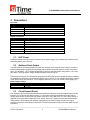
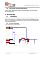
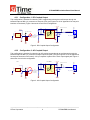
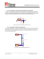
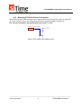
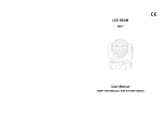
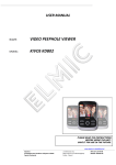
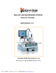
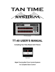
SiT6096EBB Manual Rev. 1.4
June, 2013
SiT6096EBB Evaluation Board User Manual for
SiT153x/4x Ultra-Low power 32kHz Oscillators
1
2
3
SiT6096EBB Evaluation Boards Introduction ........................................................................................ 1
Board information................................................................................................................................... 1
Connectors ............................................................................................................................................. 2
3.1
DUT Power .................................................................................................................................... 2
3.2
Buffered Clock Output ................................................................................................................... 2
3.3
Clock Output (Direct) ..................................................................................................................... 2
3.4
DUT Current Consumption Measurement .................................................................................... 3
4 Application Notes ................................................................................................................................... 3
4.1
Configurations ............................................................................................................................... 3
4.2
General Configuration ................................................................................................................... 3
4.2.1 Configuration 1: DC-Coupled Output ........................................................................................ 4
4.2.2 Configuration 2: AC-Coupled Output ........................................................................................ 4
4.2.3 Configuration 4: Direct Output with Additional Load Capacitor ................................................. 5
4.2.4 Configuration 5: DUT Power Supply Filter ................................................................................ 5
4.2.5 Measuring SiT153x/4x Current Consumption ........................................................................... 6
Appendix A .................................................................................................................................................... 7
A1: Board schematic ..................................................................................................................................... 7
1 SiT6096EBB Evaluation Boards Introduction
The SiT6096EBB evaluation board provides the ability to evaluate the functionality of SiT153x/4x 32kHz
oscillators on a simple board that makes it easy to power up the oscillator and observe the output
buffered through an operational amplifier. The analog buffer isolates the device from the significant
loading, which is important for performing best waveform and current measurements.
The SiT6096EBB supports the following package sizes: 2.0 x 1.2 mm.
2 Board information
A PCB view of the SiT6096EBB board with component reference designator call out is shown in Figure
A2 (SiT6096EBB layout).
-------------------------------------------------------------------------------------------------------------------------------------------SiTime Corporation
1
SiT6096EBB User Manual
SiT6096EBB Evaluation Board User Manual
3 Connectors
Overview:
Designator
J2
J3
J1
J6
J4
Purpose
DUT Power
Buffer Power
Buffer output
Direct output
DUT Consumption Current measurement
Mating connectors:
Designator
Mating connectors (Digi-Key Part Numbers)
J2
WM2613-ND
J3
WM2626-ND
J4
WM2613-ND
Crimps for J2, J3, J4 WM6685CT-ND, 7pcs
J6
H2011-ND
Crimps for J6
H9999-ND, 2pcs
J1
A97594-ND
Pin-1 orientation of the chip is defined by a chamfer and dot in the silkscreen pattern.
3.1
DUT Power
Evaluation boards have input two-pin connector J2 for power supply. Pins polarities are identified on the
silkscreen pattern near connector.
3.2
Buffered Clock Output
This EVB uses an operational amplifier to buffer the oscillator clock output to make it easy to connect to
test and measurement equipment through SMA cables without loading the ultra-low power clock output
driver. The ADA4817-1 FET operational amplifier is used in a unity gain buffer configuration. It is a unitygain stable, ultra-high speed, voltage feedback amplifier with FET inputs.
The three-pin connector J3 is intended for supplying the VDD power to the on-board operational amplifier.
Pin polarities are identified on the silkscreen pattern near connector J3. The operational amplifier requires
a dual power supply and should be -3V for negative power rail (V-) and +8V for the positive supply (V+).
Buffer supply voltage:
Power rail name
Voltage
V+
+8V (max)
V-3V (min)
3.3
Clock Output (Direct)
The oscillator output is best observed through the buffered output path, using a test probe placed on the
test point TP2 or through the SMA connector J1. The buffer can be bypassed and the output can be
directly observed thru J6 2mm pitch pin header connector or using test point TP1 (see Figures A2-A3 of
Appendix A for test points arrangement on the board). Section 4.1 shows recommended measurement
configurations. When probing the oscillator output directly, the probe loading can affect the output
waveform and power consumption of the device. SiTime recommends active probes with 10MΩ and 1pF
impedance.
-------------------------------------------------------------------------------------------------------------------------------------------SiTime Corporation
2
SiT6096EBB User Manual
SiT6096EBB Evaluation Board User Manual
3.4
DUT Current Consumption Measurement
Two-pin connector J4 enables measuring the current consumption of the SiT153x/4x device. To measure
the current properly, remove zero-ohm resistor R3, and connect the DMM or other current measuring
device across this connector.
4 Application Notes
4.1
Configurations
SiT6096EBB supports multiple configurations for evaluating AC and DC coupled output modes of SiTime
SiT153x/4x oscillator. In addition, this EVB provides the ability to add additional load capacitance and to
bypass the output buffer. Figure A1 (see Appendix A) shows the schematic of SiT6096EBB. Components
labeled “DNP” are not assembled. Components which are common to all listed bellow configurations have
nominal values assigned to them.
4.2
General Configuration
Figure 1 shows general shipment configuration.
Current measurement Connector
VDUT
1
2
R3 Desolder for
0 current measurement
J4
VDUT
i
C1
DNP
DUT
U1
SiT153x/4x
1
DUT Power Connector
4.7V MAX
2
1
2
J2
NC
VDD
GND OUT
Additional
load Cap
Pin1 Connector
GND
4
TP1
R1
3 OUT_TP
0
C2
DNP
To Buffer (OpAmp)
DC coupled
R2
500M
1
2
J6
GND
1
2
OUT
GND
GND
J5
DNP
GND
GND
Figure 1: General EVB Configuration
-------------------------------------------------------------------------------------------------------------------------------------------SiTime Corporation
3
SiT6096EBB User Manual
SiT6096EBB Evaluation Board User Manual
4.2.1
Configuration 1: DC-Coupled Output
This configuration is intended for observing a DC coupled output through an oscilloscope through the
buffered output at SMA (J1) connector or test point (TP2) (see Figures A1-A2 of Appendix A for test point
locations on the board). Figure 2 shows the circuit for this configuration.
DUT
VDUT
1
U1
SiT153x/4x
1
2
NC
VDD
GND OUT
V+_BUFFER
OUT Buffer
Buffer Out Test Point
OUT
DNP
J1
U2
R6
C6
DNP 10
DUT Out Test Point
4
TP1
3
3
R1
OUT_TP
OUT
0
For DC coupling:
R1 – 0 Ohm
R2 - 500MOhm
1
C2
DNP
2
4
PD
+Vs
FB
OUT
-IN
NC
+IN
-Vs
8
TP2
7
R5
6
49.9
C3
0.1
5
OUT_BUFFERED
1
C5
1.0
2 3 4 5
SMA_Connector
EPAD
R2
500M
ADA4817-1
2
GND
J6
GND
GND
GND
V-_BUFFER
GND
GND
Figure 2: DC-Coupled Output Configuration
4.2.2
Configuration 2: AC-Coupled Output
This configuration is intended for observing an AC-coupled output through an oscilloscope through the
buffered output at SMA (J1) connector or Buffer output test point (TP2) (see Figures A1-A2 of Appendix A
for test point locations on the board). A 0.1µF capacitor is placed in the clock output signal path. Figure 3
shows the circuit for this configuration.
DUT
1
U1
SiT153x/4x
2
NC
VDD
GND OUT
Buffer Out Test Point
OUT
DNP
J1
U2
VDUT
1
V+_BUFFER
OUT Buffer
R6
C6
DNP 10
DUT Out Test Point
4
TP1
3
3
R1
OUT_TP
OUT
0.1 uF Cap
C2
DNP
1
2
For AC coupling:
R1 – 0.1µF Cap
R2 - 500MOhm
4
R2
500M
PD
+Vs
FB
OUT
-IN
NC
+IN
-Vs
8
TP2
7
R5
6
49.9
C3
0.1
5
1
C5
1.0
2 3 4 5
SMA_Connector
EPAD
ADA4817-1
2
GND
J6
GND
OUT_BUFFERED
GND
GND
GND
V-_BUFFER
GND
Figure 3: AC-Coupled Output Configuration
-------------------------------------------------------------------------------------------------------------------------------------------SiTime Corporation
4
SiT6096EBB User Manual
SiT6096EBB Evaluation Board User Manual
4.2.3
Configuration 4: Direct Output with Additional Load Capacitor
This configuration is intended for observing direct oscillator output with a passive high input impedance
(> 1 MΩ || < 1 pf) scope probe at test point TP1 (see Figures A1-A2 of Appendix A for test points on the
board) or to connect the oscillator output to end user system using 2 mm pitch header connector J6 with
an optional user defined load capacitor C2. Figure 4 shows the circuit for this configuration.
VDUT
DUT
U1
SiT153x/4x
1
NC
2
VDD
GND OUT
DUT Out Test Point
4
3
TP1
R1
OUT_TP
DNP
Additional
load Cap
C2
DNP
For direct connection:
R1 – DNP
1
2
J6
GND
GND
GND
Figure 4: Circuit for observing direct oscillator output.
4.2.4
Configuration 5: DUT Power Supply Filter
This configuration intended for providing power filter for oscillator by soldering user defined capacitor C1.
Figure 5 shows circuit for this configuration. The DUT power filtering is not required in common cases. It
should be used only if power supply noise is significant or to cancel parasitic inductance effect of long
wires from Power Supply to EVB.
Current meas Connector
VDUT
1
2
R3
0
J4
Optional DUT Power filter
C1
DNP
DUT Power Connector
4.7V MAX
1
2
J2
GND
Figure 5: Circuit for providing DUT power filter.
-------------------------------------------------------------------------------------------------------------------------------------------SiTime Corporation
5
SiT6096EBB User Manual
SiT6096EBB Evaluation Board User Manual
4.2.5
Measuring SiT153x/4x Current Consumption
When measuring the SiT153x/4x supply current, simply remove jumper resistor R3 using 2-pin connector
J4. Figure 6 shows circuit for this configuration and connect a precision DMM to connector J4.
DUT current consumption: approximately 800 nA (no load), TA = 25°C
Current measurement Connector
1
2
J4
VDUT
R3 Desolder for
DNP current measurement
Figure 6: DUT Supply Current Measurement.
-------------------------------------------------------------------------------------------------------------------------------------------SiTime Corporation
6
SiT6096EBB User Manual
SiT6096EBB Manual Rev. 1.4
June, 2013
Appendix A
A1: Board schematic
Current meas Connector
V+_BUFFER
VDUT
1
2
R3 Desolder for
0 current measurement
J4
C10
1.0
C8
0.1
Optional DUT Power filter
C1
DNP
GND
DUT
OUT Buffer
Buffer Out Test Point
OUT
DNP
J1
U2
1
U1
SiT153x/4x
1
DUT Power Connector
4.7V MAX
2
1
2
NC
VDD
GND OUT
4
3
Additional
load Cap
Pin1 Connector
3
R1
OUT_TP
C2
DNP
GND
1
OUT
For AC coupling:
R1 – 0.1µF cap
R2 - 500MOhm
4
PD
+Vs
FB
OUT
-IN
NC
+IN
-Vs
TP2
7
R5
6
49.9
C3
0.1
5
ADA4817-1
GND
J6
GND
C9
0.1
GND
GND
C11
Turret and post
For probe clip
V+_BUFFER
J3
TR1
C4
10.0
C7
10.0
1.0
V-_BUFFER
Buffer Power Connector
1
2
3
1
GND
2 3 4 5
EPAD
R2
500M
GND
+8V MAX
-3V MIN
1
SMA_Connector
GND
J5
DNP
OUT_BUFFERED
C5
1.0
2
GND
1
2
2
TP1
0
J2
R6
C6
DNP 10
DUT Out Test Point
8
GND
J7
GND
V-_BUFFER
Figure A1: SiT6096EBB schematic
-------------------------------------------------------------------------------------------------------------------------------------------SiTime Corporation
7
SiT6096EBB User Manual
GND
SiT6096EBB Manual Rev. 1.4
June, 2013
A2: Board layout
Current measurement
jumper resistor
Direct out test
point
Buffer power
connector
AC/DC coupling
capacitor/resistor
Buffer output
connector
Buffer output
test point
DUT current
measurement
connector
Optional load
capacitor
DUT power
connector
Direct output
connector
Optional power
filter capacitor
Posts for scope
GND clip
Figure A2: SiT6096EBB layout
-------------------------------------------------------------------------------------------------------------------------------------------SiTime Corporation
8
SiT6096EBB User Manual
SiT6096EBB Evaluation Board User Manual
SiTime Corporation
990 Almanor Avenue
Sunnyvale, CA 94085
USA
Phone: 408-328-4400
http://www.sitime.com
© SiTime Corporation, 2008-2009. The information contained herein is subject to change at any time without notice. SiTime
assumes no responsibility or liability for any loss, damage or defect of a Product which is caused in whole or in part by (i) use of any
circuitry other than circuitry embodied in a SiTime product, (ii) misuse or abuse including static discharge, neglect or accident, (iii)
unauthorized modification or repairs which have been soldered or altered during assembly and are not capable of being tested by
SiTime under its normal test conditions, or (iv) improper installation, storage, handling, warehousing or transportation, or (v) being
subjected to unusual physical, thermal, or electrical stress.
Disclaimer: SiTime makes no warranty of any kind, express or implied, with regard to this material, and specifically disclaims any
and all express or implied warranties, either in fact or by operation of law, statutory or otherwise, including the implied warranties of
merchantability and fitness for use or a particular purpose, and any implied warranty arising from course of dealing or usage of
trade, as well as any common-law duties relating to accuracy or lack of negligence, with respect to this material, any SiTime product
and any product documentation. Products sold by SiTime are not suitable or intended to be used in a life support application or
component, to operate nuclear facilities, or in other mission critical applications where human life may be involved or at stake.
-------------------------------------------------------------------------------------------------------------------------------------------SiTime Corporation
9
SiT6096EBB User Manual