1
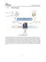
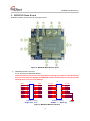
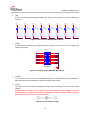
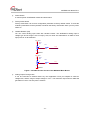
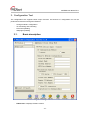
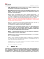
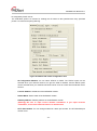
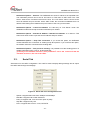
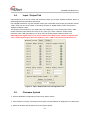
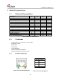
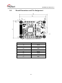
WIZ220IO / WIZ220IO-EVB User’s Manual (Ver. 1.1) © 2010 WIZnet Co., Ltd. All Rights Reserved. For more information, visit our website at www.wiznet.co.kr WIZ220IO User Manual V1.1 Document History Information Revision Ver. 1.0 Data 2010. 04. Ver. 1.1 2010. 06. Description Release with WIZ220IO launching - Added description of notification option as updating firmware. : The firmware ver.1.1 supports output control through the notification port. (The firmware ver.1.0 supports only transmission I/O status.) - modified description of configuration tool. : The transmitting period unit of notification option is changed from ‘1sec’ to ‘10ms’ as updating firmware. : [Update I/O States] button in ‘Input/Output’ tab supports auto-clicking with time period. -2- WIZ220IO User Manual V1.1 Table of Contents 1. Introduction ......................................................................................................................................... 6 1.1. Main Function............................................................................................................................................................. 6 1.2. Specification ................................................................................................................................................................ 7 1.3. Block Diagram ............................................................................................................................................................ 8 2. WIZ220IO Base Board ........................................................................................................................ 9 3. Configuration Tool ............................................................................................................................ 12 4. 5. 6. 3.1. Basic description .................................................................................................................................................... 12 3.2. Network Tab ............................................................................................................................................................. 13 3.3. Serial Tab .................................................................................................................................................................... 15 3.4. Input / Output Tab ................................................................................................................................................ 16 3.5. Firmware Upload .................................................................................................................................................... 16 3.6. Webpage Upload ................................................................................................................................................... 17 Notification Data Protocol .............................................................................................................. 19 4.1. Sending Protocol.................................................................................................................................................... 19 4.2. Receiving Protocol ................................................................................................................................................. 20 WIZ220IO Specification ................................................................................................................... 22 5.1. Electrical Characteristics ...................................................................................................................................... 22 5.2. Pin Header ................................................................................................................................................................ 22 5.3. RJ-45 connector ..................................................................................................................................................... 22 5.4. Board Dimensions and Pin Assignment ...................................................................................................... 23 Warranty ............................................................................................................................................. 24 -3- WIZ220IO User Manual V1.1 Tables Table 1. WIZ220IO Specification ........................................................................ 7 Table 2. WIZ220IO Base Board Specification ........................................................ 7 Table 3. Frame format of notification sending parameters. ........................................ 19 Table 4. Sending parameter description in the notification function. ............................. 19 Table 5. Frame format of notification receiving parameters. ....................................... 20 Table 6. Receiving parameter description in the notification function. ........................... 20 Table 7. Electrical characteristics ...................................................................... 22 Table 8. RJ-45 Pin Assignment ......................................................................... 22 Table 9. WIZ220IO Dimension ......................................................................... 23 -4- WIZ220IO User Manual V1.1 Figures Figure 1. Block Diagram 8 Figure 2. WIZ220IO Base Board Layout 9 Figure 3. WIZ220IO Module Interface 9 Figure 4. LED circuit of WIZ220IO Base Board 10 Figure 5. DI Switch of the WIZ220IO Base Board 10 Figure 6. Power adapter polarity 10 Figure 7. Variable Resistor Circuit of the WIZ220IO Base Board 11 Figure 8. Configuration Tool 12 Figure 9. Network Tab of the Configuration Tool 14 Figure 10. Serial Tab of the Configuration Tool 15 Figure 11. Input / Output Tab of the Configuration Tool 16 Figure 12. Firmware uploading window 17 Figure 13. Complete firmware uploading window 17 Figure 14. RJ-45 PIN Assignment 22 Figure 15. WIZ220IO Module Dimension 23 -5- WIZ220IO User Manual V1.1 1. Introduction WIZ220IO is an embedded remote I/O module which is able to control and monitor I/O port remotely via Internet. It is possible to monitor and control I/O port by using Windows application program or the embedded Web server. There are 16 digital I/O ports and 4 analog I/O supported by WIZ220IO. Additionally, the firmware and embedded webpage can also be updated remotely through the Ethernet. WIZ220IO-EVB is the evaluation base board for users to evaluate WIZ220IO module quickly. There are 8 switches used for digital input test and 8 LEDs for digital output test, and a variable register for analog input test included in this evaluation board. 1.1. Main Function Operates as HTTP Server using W7100, all-in-one embedded network MCU with hardwired TCP/IP stack Provides Configuration Tool Program for easy control, monitoring and configuration Supports 10/100Mbps Ethernet 8 Digital Input Ports 8 Digital Output ports 2 Analog Input Ports with 12-bit resolution (Voltage Type) 2 Analog Output Ports with 12-bit resolution (Voltage Type) 1 UART Output Port Data acquisition and transmitting to specified host RoHS Compliant -6- WIZ220IO User Manual V1.1 1.2. Specification Architecture MCU Standard 8051 compatible in W7100 PHY Included in W7100 TCP/IP Stack Hardwired TCP/IP Stack in W7100 Network Protocols ARP, ICMP, TCP/IP, UDP, HTTP Server, DHCP Network Interface RJ-45, Auto-MDIX, Auto-Negotiation Input CMOS Digital Input Output CMOS Digital Output Network 1 UART output Baud rate : 1200bps ~ 230400bps Digital Data bit : 7bit, 8bit UART Parity : none, odd, even Stop bit : 1bit Flow control : none, RTS/CTS Input 12bit resolution. Input Range(0 ~ Vcc) Output 12bit resolution. Output Range(0 ~ 4v) Input Voltage DC 5V Power Consumption Under 280mA @ 5V Temperature 0C ~ 70C (Operation), -40C ~ 85C (Storage) Humidity 10 ~ 90% Analog Power Environment Table 1. WIZ220IO Specification Power Digital Ports Analog I/O Socket Inner pin Ø 2.0, DC Power Jack Voltage DC 5V Input 8-Switch Output 8-LED (Green chip-LED) UART D-SUB 9PIN MALE Input 2-Variable Resistor(10K ohm) Output None(Through Hole) Switch Factory Reset Switch Table 2. WIZ220IO Base Board Specification -7- WIZ220IO User Manual V1.1 1.3. Block Diagram Figure 1. Block Diagram WIZ220IO includes not only I/O controlling & monitoring but also I/O value transmission functions. The users can control or monitor via web browser in remote host PC, and configure the module’s environment parameters and check the IO status via Configuration Tool program provided by WIZnet. The interface of WIZ220IO consists of analog interface and digital interface. 12 bits resolution analog I/O, 3.3V digital output and the maximum 5.5V digital input are supported by WIZ220IO. The digital I/Os are internally pulled up. The users can use Web browser or Configuration Tool to remotely control the interfaces. Also, user can control output port by transmitting control data through the notification port. -8- WIZ220IO User Manual V1.1 2. WIZ220IO Base Board WIZ220IO module can be tested by using base board. Figure 2. WIZ220IO Base Board Layout ① WIZ220IO Module Connector It is an interface for WIZ220IO Module. [Caution] Observe pin position and align when mounting the module on the base board. Incorrect mounting can damage the WIZ220IO module and base board, and your product warranty does not cover such damage. J1 GND DI_0 DI_1 DI_2 DI_3 GND DO_0 DO_1 DO_2 DO_3 1 3 5 7 9 11 13 15 17 19 J2 2 4 6 8 10 12 14 16 18 20 GND DI_4 DI_5 DI_6 DI_7 GND DO_4 DO_5 DO_6 DO_7 5V_input 5V_input nRST_in GND P2_2 P2_4 AI_0 AI_1 AO_0 AO_1 CON20A / 2.54mm 1 3 5 7 9 11 13 15 17 19 2 4 6 8 10 12 14 16 18 20 F_RST TXD RXD GND RTS CTS GNDAA GNDAA GNDAA GNDAA CON20A / 2.54mm Digital I/O Power / Analog Figure 3. WIZ220IO Module Interface -9- GNDAA WIZ220IO User Manual V1.1 LED 8 LEDs are indicating each Digital Output ports. When the port signal is LOW, the LED light is turned on. R8 200 R9 200 DO_0 DO_2 R11 200 R12 200 DO_3 2 2 3.3V R13 200 DO_4 DO_5 LED9 LEDG-SMD 1 LED8 LEDG-SMD 1 LED7 LEDG-SMD 1 LED6 LEDG-SMD 1 LED5 LEDG-SMD 3.3V 2 3.3V 2 2 LED4 LEDG-SMD R10 200 DO_1 3.3V 1 LED3 LEDG-SMD 1 1 LED2 LEDG-SMD 3.3V 2 3.3V 2 3.3V 2 3.3V 1 ② R14 200 DO_6 R15 200 DO_7 Figure 4. LED circuit of WIZ220IO Base Board ③ Switch 8 switches are controlling each Digital Input ports. When you turn switch on, the digital port signal will be LOW. SW3 DI_0 DI_1 DI_2 DI_3 DI_4 DI_5 DI_6 DI_7 SW DIP-8 Figure 5. DI Switch of the WIZ220IO Base Board ④ D-SUB9 This connector is for an UART. The WIZ220IO’s UART port can be used for debug message or data output through the webpage. It supports RTS/CTS flow control. ⑤ Power The power can be controlled by using power switch after connecting the DC 5V (min 500mA) adapter. [Caution] Observe polarity and voltage when connecting the power adapter. Incorrect input polarity or voltage can damage the WIZ220IO module and base board, and your product warranty does not cover such damage. Figure 6. Power adapter polarity - 10 - WIZ220IO User Manual V1.1 ⑥ Power Switch It controls power of WIZ220IO module and base board. ⑦ Factory Reset button Factory reset button can recover configuration parameter to factory default values. To reset the module’s parameters to factory default, hold down the factory reset button when you turn power switch on. ⑧ Variable Resistor (VR) You can control analog input value with variable resistor. The WIZ220IO’s analog input is voltage type and its range is 0V to Vcc(5V). Also, its value was translated to 0~4095 as each input port has 12-bit resolution. VR1 VR B 1 5V_input AI_0 2 A Y R1 3 200 GNDAA VR2 VR B 1 5V_input A Y R2 AI_1 2 3 200 GNDAA Figure 7. Variable Resistor Circuit of the WIZ220IO Base Board ⑨ Analog Output Through Hole It can be connected to external device by user application. Each port outputs its value as voltage level, and the range of output voltage is ‘0~4V’. The maximum output value is 4095 that generates 4V level. The hole pitch is 2.54mm. - 11 - WIZ220IO User Manual V1.1 3. Configuration Tool The configuration tool supports below major functions. All functions of configuration tool can be performed remote area through the Ethernet. - Change module’s configuration. - I/O monitoring and controlling - Firmware uploading - Webpage uploading 3.1. Basic description Figure 8. Configuration Tool - FW Version: It displays firmware version. - 12 - WIZ220IO User Manual V1.1 - Enable Serial Debug Mode: If this mode is checked, you can monitor the status and socket message (listen OK, connect fail etc.) through serial terminal. - Board List: If you click the “SEARCH” button, all the MAC address on a same subnet will be displayed. When you check the “Direct IP Search” and enter the specified IP address, the board list will display its MAC address. - Direct IP Search: Direct IP Search can be used for searching WIZ220IO which is not installed in the same subnet. If the Direct IP Search is checked, the configuration tool use the TCP instead of UDP broadcast to search the module. Therefore, network information of the module such as IP address, subnet mask and gateway address is required for the search. [Warning] If module does not have valid network information, Direct IP Search is not available. If the module is connected to the NAT or private network, it is not possible to connect to the module from outside. - Search: The Search function is used to search all modules existing on the same LAN. By using UDP broadcast, all modules on the same subnet will be searched. The searched module is displayed as MAC address in the “Board List”. - Setting: This function is to complete the configuration change. If you select the MAC address from the “Board List”, the current configuration values of the module will be displayed. Change the configuration value and click “Setting” button to complete the configuration. After that, the module will re-initialize with the changed configuration. - Webpage: It is possible to upload ROM Image file to the internal flash memory of WIZ220IO. For more information, refer to “3.6. Webpage Upload”. - Upload: It is possible to upload new firmware file through the Ethernet. For more information, refer to “3.5. Firmware Download”. - Ping: It is used to test whether the WIZ220IO module is reachable across a network from your PC with ICMP protocol. After inputting host IP address in new pop-up window, click the “PING” button. Then, it will be displayed its result. - Firewall: It controls your PC’s firewall configuration. If board list does not display even though clicking search button, check your PC’s firewall. - Exit: Close the configuration tool program. 3.2. Network Tab In the Network Tab of the configuration tool, network information and the notification parameters can be set. The network information is for a communication through the Ethernet such as an IP address, a gateway address and a subnet mask. If the module cannot be assigned with the fixed information from ISP provider, you can set the DHCP option. By setting DHCP option, the network information can - 13 - WIZ220IO User Manual V1.1 be assigned by DHCP server. The notification option is a function for sending the I/O values to the specified host every specified period. It is useful for acquiring data log. Figure 9. Network Tab of the Configuration Tool - IP Configuration Method: You can select STATIC or DHCP. The STATIC option can be selected when your network resource can give the fixed IP address, and the DHCP option can be selected when your network has DHCP server such as a router who has DHCP server function. - Local IP Address: IP address of the WIZ220IO module. - Subnet Mask: Subnet mask of the WIZ220IO module. - Gateway address: Gateway address of the WIZ220IO module. [Warning] Be sure to input correct network information. If you input incorrect information, it can cause network collision or mal-function. - HTTP Port Number: You can change webserver’s listen port number. The HTTP default port number is 80. - 14 - WIZ220IO User Manual V1.1 - Notification Options – Protocol: The WIZ220IO can send I/O values to the specified host. The notification protocol can be set as TCP server or TCP client or UDP mode. The “TCP Server” waits for the connection trial from the host, The “TCP Client” tries to connect to the host’s IP address and port number. At the “UDP” mode, the connection establishment is not defined. After setting the IP address and port number of the host, just send data. - Notification Options – Listen Port Number: It is valid only on “TCP Server” mode. The WIZ220IO module will accept connection with listen port number. - Notification Options – Remote IP Address / Remote Port Number: It is valid on “TCP Client” and “UDP” modes. Input the host IP address and port number. - Notification Options – Keep TCP connection: If you check this option, the WIZ220IO module maintains the connection as sending keep-alive packet. If you uncheck this option, the module closes the connection after sending data. - Notification Options – Time period to sending: It is possible to set the sending period. To disable notification option, input ‘0’ to this parameter. [Causion] In the firmware version1.0, this parameter’s unit is the 1-second. From the firmware version1.1, the unit is the 10ms. 3.3. Serial Tab Serial tab is for the UART configuration. The UART is used to display debug message and to output the UART data through the webpage. Figure 10. Serial Tab of the Configuration Tool - Speed: It supports baud rate from 1200bps to 230400bps. - Data Bit: It supports 7bit or 8bit of data bit. - Parity: It supports odd, even and none option of parity. - Stop Bit: It supports only 1bit. - Flow: It supports flow control – none, RTS/CTS. - 15 - WIZ220IO User Manual V1.1 3.4. Input / Output Tab Input/Output tab is for the I/O control and monitoring. When you click the “Update I/O Status” button, it will be displayed I/O parameters at that time. In the Digital parameters, a green indicator means port is asserted ‘HIGH’ and a gray indicator means ‘LOW’. Each port can be set ‘HIGH’ as checking checkbox in ‘Digital Output Control’ and click the ‘Update I/O Status’ button. The Analog I/O has range from 0 to 4095 and it has voltage type. In the Analog input status, ‘4095’ means maximum input value that is same to ‘5V_Input’ (Vcc) value. However, analog output maximum value ‘4095’ generates 4V. In other word, the analog output maximum value is 4V. [Warning] At the digital input, if you set the switch on the base board, module recognizes it as “low”. At the digital output, when the module is “low”, LED on the base board becomes on. Figure 11. Input / Output Tab of the Configuration Tool 3.5. Firmware Upload ① Execute WIZ220IO configuration tool and click ‘Search’ button. ② If the module is correctly connected to the network, its MAC address is displayed on the ‘Board list’. ③ Select the board at the ‘Board list’ and click ‘Upload’ button. - 16 - WIZ220IO User Manual V1.1 [Warning] Before uploading through Ethernet, the network information should be set for correct network communication. The configuration tool send ping request automatically, and if there is no reply from board, it will display error message. ④ When the dialog box is shown, select the Binary file and click ‘OPEN’ button. [Warning] Be sure to use firmware only for the WIZ220IO. ⑤ You can see below status window showing ‘Processing’. Figure 12. Firmware uploading window ⑥ If the file is uploaded, ‘Complete firmware uploading’ message will be displayed. Figure 13. Complete firmware uploading window 3.6. Webpage Upload ① Execute WIZ220IO configuration tool and click ‘Search’ button. ② If the module is correctly connected to the network, its MAC address is displayed on the ‘Board list’. ③ Select the board at the ‘Board list’ and click ‘web page Upload’ button. [Warning] Before uploading through Ethernet, the network information should be set for correct network communication. The configuration tool send ping request automatically, and if there is no reply from board, it will display error message. ④ When the dialog box is shown, select the Flash Rom File System (*.rom) file and click ‘OPEN’ button. [Warning] The Flash Rom File system should be created by usinig “Rom File Maker Tool rev3.0”. For the detail, refer to “3.6.1. Use of Rom File Maker rev3.0”. ⑤ If the file is uploaded, ‘Complete webpage uploading’ message will be displayed. - 17 - WIZ220IO User Manual V1.1 3.7. Rom File Maker rev3.0 Rom File Maker rev3.0 is the tool for creating ROM Image which enables the webpage to be stored in the Flash memory. ① Select the webpage by using ‘Add Files’ button. [Warning] There is limitation of file number in selecting at a time. (Normally, max 15 files can be selected simultaneously). If there are more files, use “Add Files” button for the several times. ② Select ‘Rom Image File’ option. If you click ‘Make Image’ button, ‘*.rom’ file can be created. [Warning] The limitation of the ROM image size is 20476bytes. If the file size is over 20476bytes, it does not guarantee the normal operation. - 18 - WIZ220IO User Manual V1.1 4. Notification Data Protocol WIZ220IO uses the pre-defined notification protocol to transfer the I/O status to the specified server, and control the output port by using received commands. Both TCP and UDP are supported in this function. In the TCP mode, socket should be established for exchanging data. 4.1. Sending Protocol The length of I/O status data to be transferred is 45 bytes in total. The data format is defined as follows. 0 0x00 0x10 0x20 1 2 3 4 5 6 7 DI[0] DI[1] DI[2] DI[3] ID DO[4] IP address DO[5] DO[6] 8 9 A B SEQ DO[7] AI_0 AI_1 DI[4] DI[5] AO_0 DI[6] DI[7] AO_1 C D MAC address DO[0] DO[1] End char E F DO[2] DO[3] Table 3. Frame format of notification sending parameters. Field Size(byte) value Description ID 6 WIZ220 module’s ID. Fixed value as ‘WIZ220’.(Hex: 57 49 5A 32 32 30) SEQ 4 variable Sequence number of data transmission. This value set to 0 when connection is closed in TCP mode. MAC 6 Fixed module’s MAC address IP 4 Fixed module’s IP address. DI[n] 8 ‘H’ or ‘L’ digital input value. It can be set to ‘H’(0x48) or ‘L’(0x4C) as input port status. DO[n] 8 ‘H’ or ‘L’ digital output value. It can be set to ‘H’(0x48) or ‘L’(0x4C) as output port status. AI_0 2 variable analog input #0. The range of value is 0x0000~0x0FFF. AI_1 2 variable analog input #1. The range of value is 0x0000~0x0FFF. AO_0 2 variable analog output #0. The range of value is 0x0000~0x0FFF. AO_1 2 variable analog output #1. The range of value is 0x0000~0x0FFF. End char 1 0xFF end char of notification sending parameter Table 4. Sending parameter description in the notification function. - Total data size : 45 bytes - [ID], [MAC], [IP], and [End char] fields are fixed. - The transmitted digital value in Firmware v1.0 is different from above Table 4. The value will be 0x00 when the port in low voltage level, as well the value 0x01 indicates the port is in high voltage level. - 19 - WIZ220IO User Manual V1.1 4.2. Receiving Protocol Data transmission and the output port can be controlled via notification port. Please note this function is only available in Firmware v1.1 or later. 0 0x00 0x10 0x20 0x30 1 2 3 4 5 ID DO[2] DO[3] DO[4] DO[5] DO[6] DO[7] 6 7 8 9 OP[0] OP[1] OP[2] OP[3] AO_0 AO_1 UART A B C D IP E DO[0] F DO[1] End char Table 5. Frame format of notification receiving parameters. Field Size(byte) value Description ID 6 WIZ220 module’s ID. Fixed value as ‘WIZ220’.(Hex: 57 49 5A 32 32 30) OP 4 ‘O’ or not Output control select flag. ‘O’(0x4F) means user would like to control specified port. if OP field is not ‘O’, the module does not change specified port. OP[0] : Digital Output OP[1] : Analog Output #0 OP[2] : Analog Output #1 OP[3] : UART Output IP 4 Fixed module’s IP address DO[n] 8 ‘H’ or ‘L’ digital output value. It can be set to ‘H’(0x48) or ‘L’(0x4C). If this value is not ‘H’ or ‘L’, port output is not changed. AO_0 2 AO_1 2 UART 32 0x0000 analog output #0. The range of value is 0x0000~0x0FFF. ~ 0x0FFF If you input this over 0x0FFF, it will be set 0x0FFF. 0x0000 analog output #1. The range of value is 0x0000~0x0FFF. ~ 0x0FFF If you input this over 0x0FFF, it will be set 0x0FFF. variable UART value can be inputted max. 32 bytes. If data is null(0x00), the module stop output UART data. End char 1 0x00 end char of notification receiving parameter Table 6. Receiving parameter description in the notification function. - Total data size : 59 bytes - User should send whole control data at a time. - The module does not control output port as below conditions: mismatch ID value OP[n] value is not ‘O’(0x4F). - 20 - WIZ220IO User Manual V1.1 - mismatch IP value : You should input module’s IP address as hex value. mismatch [End char] value If you send data to module over 59 bytes, excess data will be ignored. - 21 - WIZ220IO User Manual V1.1 5. WIZ220IO Specification 5.1. Electrical Characteristics Parameters Min Typ Max Units Input Voltage (Vcc) 4.5 5 5.5 V High Level Digital Input 2.0 - 5.5 V Low Level Digital Input -0.5 - 0.8 V High Level Digital Output 3.3 - - V Low Level Digital Output - - 0.4 V 8 mA Vss - Vcc V .001 ±1 μA - 4 V 15 24 mA 0 - 70 ℃ -40 - 85 ℃ 280 mA Digital Output Current Analog Input Range Analog Input Leakage Current Analog Output Range 0 Analog Output Short Circuit Current Operation Temperature Storage Temperature Power Consumption(@DC5V) Table 7. Electrical characteristics 5.2. Pin Header - 2x10Pin Dual Line, 2.54mm Pitch, 12mm height - Lead length = 6mm - Straight Type - Gold Plating - Current Rating:1A - Insulation Resistance:500Mohm - Dielectric Withstanding Voltage:500VAC 5.3. RJ-45 connector Figure 14. RJ-45 PIN Assignment - 22 - Pin Signal 1 TX+ 2 TX- 3 RX+ 6 RX- Table 8. RJ-45 Pin Assignment WIZ220IO User Manual V1.1 5.4. Board Dimensions and Pin Assignment Figure 15. WIZ220IO Module Dimension Symbol mm A 45.00 a1 2.18 a2 4.00 B 66.50 b1 63.00 b2 13.34 b3 4.00 C 3.00 Table 9. WIZ220IO Dimension - 23 - WIZ220IO User Manual V1.1 6. Warranty WIZnet Co., Ltd. offers the following limited warranties applicable only to the original purchaser. This offer is non-transferable. WIZnet warrants our products and its parts against defects in materials and workmanship under normal use for period of standard ONE(1) YEAR for the WIZ220IO module and labor warranty after the date of original retail purchase. During this period, WIZnet will repair or replace a defective products or part free of charge. Warranty Conditions: The warranty applies only to products distributed by WIZnet or our official distributors. 1. The warranty applies only to defects in material or workmanship as mentioned above in 7. Warranty. 2. The warranty applies only to defects which occur during normal use and does not extend to damage to products or parts which results from alternation, repair, modification, faulty installation or service by anyone other than someone authorized by WIZnet ; damage to products or parts caused by accident, abuse, or misuse, poor maintenance, mishandling, misapplication, or used in violation of instructions furnished by us ; damage occurring in shipment or any damage caused by an act of God, such as lightening or line surge. Procedure for Obtaining Warranty Service 1. Contact an authorized distributors or dealer of WIZnet for obtaining an RMA (Return Merchandise Authorization) request form within the applicable warranty period. 2. Send the products to the distributors or dealers together with the completed RMA request form. All products returned for warranty must be carefully repackaged in the original packing materials. 3. Any service issue, please contact to [email protected] - 24 - Mouser Electronics Authorized Distributor Click to View Pricing, Inventory, Delivery & Lifecycle Information: WIZnet: WIZ220IO