1
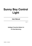
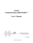
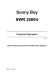
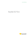
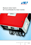
Sunny Display Supplement to the Sunny Boy User Manual Version 1.0 Sunny Boy Statusand Measurement Value Display SUNDIS-11:NE1000 Sunny Display Supplement to the Sunny Boy User Manual Alteration Review DocumentNumber SUNDIS -11:NE0500 1 ) Version and Alteration 1 Review ) 1.0 A Comments Author First Edition, as translation from first German issue Salisbury A: Alterations due to faulty documents or improvement of the documentation B: Alterations maintaining full or upward compatibility C: Alterations limiting or excluding compatibility Name Release SUNDIS-11:NE Date Signature J. Lengemann -2- SMA Regelsysteme GmbH Sunny Display Supplement to the Sunny Boy User Manual Explanation of Symbols used in this Document To enable optimal usage of this manual and safe operation of the device during installation, operation and maintenance routines, please note the following description of symbols: This indicates a feature that is important either for optimal and comfortable usage or optimal operation of the system. Example: „Useful C routines for this purpose are on the support disk.“ This indicates a fact or feature very important for the safety of the user and / or can cause a serious hardware defect if not appropriately applied. Example: „Disconnect the mains plug before opening the case!“ This indicates an example. SUNDIS-11:NE -3- SMA Regelsysteme GmbH Sunny Display Supplement to the Sunny Boy User Manual Content 1 Introduction......................................................................................................... 5 2 Installation of the Sunny Display ........................................................................ 6 3 Operation............................................................................................................ 9 4 Technical Data ................................................................................................. 11 5 Warranty Regulations and Liability ................................................................... 12 SUNDIS-11:NE -4- SMA Regelsysteme GmbH Sunny Display Supplement to the Sunny Boy User Manual 1 Introduction Thank you very much for purchasing a Sunny Display. The Sunny Display will provide detailed information about the performance of your Sunny Boy inverter. This is a very short manual and is split into the following sections: Introduction → Chapter 1 Installation of the Sunny Display → Chapter 2 Operation → Chapter 3 Technical Data → Chapter 4 Warranty Regulations and Liability → Chapter 5 The latest information is always available on our internet-site. You can also register for automatic updates of the documentation concerning the Sunny Boy products. Simply send an Email to [email protected] or visit our Homepage http://www.sma.de. SUNDIS-11:NE -5- SMA Regelsysteme GmbH Sunny Display Supplement to the Sunny Boy User Manual 2 Installation of the Sunny Display The lid of the Sunny Boy must be exchanged if you are upgrading the Sunny Boy with a Sunny Display unit. Pay attention to the safety regulations in your Sunny Boy Manual when you take the lid of the Sunny Boy. Pay attention to the ESD countermeasures in order to protect the display unit and the Sunny Boy itself when you install the Sunny Display. Be careful and make sure you are connected to ground before you touch any electronic components. Procedure: • disconnect the the AC Side of the Sunny Boy. This is done with the fuse on the household distribution. • disconnect the the DC Side (PV voltage) from the Sunny Boy. Note: Some Sunny Boy inverters (Sunny Boy 700 and Sunny Boy 850) require that you take the lid off in order to disconnect the DC voltage. Never disconnect the PV voltage when the Sunny Boy is feeding to the grid! Always disconnect the AC side first. • wait for 30 minutes for internal voltages to discharge before you proceed. • remove the lid with the 4 screws on the sides and disconnect the yellow-green cable. SUNDIS-11:NE -6- SMA Regelsysteme GmbH Sunny Display Supplement to the Sunny Boy User Manual pins for mounting display unit LEDs SMA SWR-SRR VX.xx 2 3 1 2 3 SMA SWR-BFR VX.xx 1 ENS1 150 V 200 V ENS2 N Figure 2.1: Sockets on the control board • Insert the display unit carefully in the 3 sockets on the control board (see Figure 2.1 above). The 3 LEDs must fit exactly through 3 holes in the display unit. Carefully push the display unit down until the pins are entirely in the sockets. Do not use brute force. The display unit should easily sink into the right position. SUNDIS-11:NE -7- SMA Regelsysteme GmbH Sunny Display Supplement to the Sunny Boy User Manual Figure 2.2: Sunny Boy with mounted display unit • Close the Sunny Boy with the new lid. Do not forget to connect the yellow-green PE cable. • Reconnect the Sunny Boy to the DC and the AC side in the opposite order as described above. SUNDIS-11:NE -8- SMA Regelsysteme GmbH Sunny Display Supplement to the Sunny Boy User Manual 3 Operation How to switch on the background light You can switch on the background light by knocking on the lid. After 2 minutes the light will be automatically turned off. Display messages on power-up On power-up the Sunny Display replies with it’s software version number: ?r²?c« †² ?uŠª«??PM±± software version number Figure 3.1: Initial Message After 5 Seconds type and Network address of the inverter appear in the first line: s²Š????vqVQTLPU mŠ¬‘‰ª?????????Q Sunny Boy type Network address Figure 3.2: Type of used inverter and Network address The Sunny Display receives the measuring channel information of the inverter. This process takes ca. 3 minutes. s²Š????vqVQTLPU b¬‰°?????UU Sunny Boy type Count-down of remaining data packages Figure 3.3: Countdown SUNDIS-11:NE -9- SMA Regelsysteme GmbH Sunny Display Supplement to the Sunny Boy User Manual Display messages in operation mode The display shows the most important information of your inverter. The following three figures explain the messages. Each message appears for 5 seconds. Afterwards the cycle starts from the beginning. First you can see the current output power and solar generator voltage: o†"?????????XORv u&?????????PUQu current output power solar generator voltage Figure 3.4: Displaying of Pac and Vpv These values are followed by the energy yield (up to now) and total operating time: dLs¬† ?PQSMS)v* *Ls¬† ?????TPQ* produced energy operating time Figure 3.5: Message of E-Total and h-Total After that the energy yield of the current day and the operating mode are displayed: dL¬‰†²??RMWU)v* l‰Š?????????loo energy yield of today operating mode Figure 3.6: Energy yield and operation mode In case of a failure the status line changes to “Disturbance“: dL¬‰†²?????R)v* l‰Š?c«¬ª‡†"Š Figure 3.7: Status message This is followed by reason of the failure is displayed for 15 seconds: dªªª????t†"La‹ª reason of the failure Figure 3.8: Error message Now the information restarts. You can find an overview of all status- and errormessages in the technical documentation of your Sunny Boy. SUNDIS-11:NE - 10 - SMA Regelsysteme GmbH Sunny Display Supplement to the Sunny Boy User Manual 4 Technical Data Dimensions: 160 x 75 x 20 mm Display: 2 x 16 Characters Weight: ca. 100 g SUNDIS-11:NE - 11 - SMA Regelsysteme GmbH Sunny Display Supplement to the Sunny Boy User Manual 5 Warranty Regulations and Liability You have purchased a product, which was thoroughly checked before delivery. If your device nevertheless is defective or shows malfunction during the guarantee period, please contact your distributor or company that installed the device. Guarantee The guarantee period is 24 months from the date of purchasing the device by the end user. It ends at the latest 30 months after the shipping date from SMA, and includes all defects caused by material or manufacturing faults. The guarantee period for guarantee repairs or compensation deliveries ends 12 months after delivery, but runs at least until the expiration of the original guarantee period for the purchased device. SMA will only guarantee services, if the rejected device is sent back to SMA together with a copy of the invoice the distributor has issued to the customer. The type identification sign on the device must be completely legible. In any other case SMA reserves its right to refuse guarantee services. Conditions The device will be repaired in its fabrication site without invoice for material and labor, or a replacement device will supplied. The objected device is to be sent back to SMA without charges in the original packing or in a transport packing of equal quality. The customer has to grant SMA the necessary time and opportunity to repair the defects. SUNDIS-11:NE - 12 - SMA Regelsysteme GmbH Sunny Display Supplement to the Sunny Boy User Manual Exclusion of Liability Excluded are any guarantee claims and liabilities for direct or consequential damages due to • transportation damages, • improper installation or operation, • alterations, modifications or unauthorized repairing attempts, • inappropriate use or operation, • insufficient air circulation for the device, • violation of according safety regulations (VDE etc.), • or force majeure (lightning, overvoltage, storm, fire). Sequential Damages SMA in no case will cover any liability for damages resulting from the use of a Sunny Display (including and without restriction for direct and indirect damages of used hardware, personal damages, profits lost, operating troubles, loss of data, or any financial losses). Further or other claims for direct and indirect damages, especially including claims for damages from positive contract violation, are excluded insofar as not otherwise compelling stated by law. Sunny Boy and SMA are registered trademarks of the SMA Regelsysteme GmbH. We accept all trademarks mentioned in this manual. SUNDIS-11:NE - 13 - SMA Regelsysteme GmbH