1
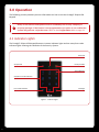
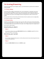
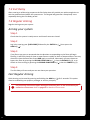
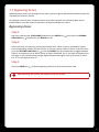
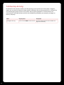
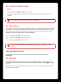
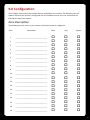
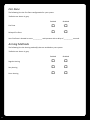
PRT-KLES
Protégé® Eclipse LED Keypad
User Manual
The specifications and descriptions of products and services contained in this manual were correct at the time of printing. Integrated Control Technology Limited
reserves the right to change specifications or withdraw products without notice. No part of this document may be reproduced, photocopied, or transmitted in any
form or by any means (electronic or mechanical), for any purpose, without the express written permission of Integrated Control Technology Limited. Designed and
manufactured by Integrated Control Technology Limited. Protégé® and the Protégé® Logo are registered trademarks of Integrated Control Technology Limited. All
other brand or product names are trademarks or registered trademarks of their respective holders.
© Copyright Integrated Control Technology Limited 2003-2010. All rights reserved.
Table of Contents
1.0
Welcome.............................................................................................................................2
2.0
How to Read this Manual....................................................................................................3
3.0
Operation............................................................................................................................4
3.1 Indicator Lights..................................................................................................................... 4
3.2 Arm/Armed Indicator........................................................................................................... 5
3.3 Disarmed Indicator............................................................................................................... 5
3.4 Power/Trouble Indicator...................................................................................................... 5
3.5 Message Indicator................................................................................................................ 5
3.6 Memory Indicator................................................................................................................ 5
3.7 Error Code Indicator............................................................................................................. 6
3.8 Zone Display and Error Codes............................................................................................... 6
4.0
Audible Tones......................................................................................................................7
5.0
Keypad Operation................................................................................................................8
5.1 Second Function................................................................................................................... 9
6.0
Trouble Display..................................................................................................................10
7.0
Arming/Disarming.............................................................................................................11
7.1 Entry Delay......................................................................................................................... 11
7.2 Disarming........................................................................................................................... 11
7.3 Exit Delay........................................................................................................................... 12
7.4 Regular Arming.................................................................................................................. 12
7.5 Stay Arming........................................................................................................................ 13
7.6 Force Arming...................................................................................................................... 14
7.7 Bypassing Zones................................................................................................................. 15
7.8 One Key Arming.................................................................................................................. 16
8.0
Special Features.................................................................................................................17
8.1 Alarm Memory................................................................................................................... 17
8.2 Access Control.................................................................................................................... 18
8.3 Disable Audible Output...................................................................................................... 18
8.4 Enabling Audible Output.................................................................................................... 19
8.5 Panic Alarm........................................................................................................................ 19
8.6 Message............................................................................................................................. 19
8.7 Smoke Reset....................................................................................................................... 20
9.0 Configuration.....................................................................................................................21
10.0 Warranty...........................................................................................................................24
33
1.0 Welcome!
Thank you for purchasing the Protégé® Eclipse LED Keypad by Integrated Control Technology. The
Protégé® System is an advanced technology security system specifically designed to enhance the
functionality of security, building automation and access control by providing a complete
integrated solution with flexible local monitoring and offsite communication.
The elegant Protégé® Eclipse LED Keypad allows complete control of your security and access
control system with a user friendly LED display and 15 key keypad.
All the actions performed in your system will be executed and displayed through the Eclipse
Keypad. Therefore, before using your Protégé® Integrated Alarm and Access Control System, we
highly recommend you read this manual carefully and have your security professional or property
manager explain basic system operation to you.
Please consult the configuration section at the end of this manual to find out how your system is
configured. Some features may not be available depending on your system configuration.
Optional management software is available (Protégé® System Management Suite) and is
recommended to enhance your productivity when using the Protégé® System. For more
information visit the www.incontrol.co.nz or ask your system administrator.
2
2.0 How to Read this Manual
Before using the Protégé® Eclipse LED Keypad (PRT-KLES) it is recommended that the user manual
is read carefully and understood. The icons below are used throughout the user manual and are
there to help with understanding.
!
Indicates a warning or advisory message relating to the section or location.
?
Indicates a hint or suggestion that relates to the section or location.
[TEXT]
Bold text enclosed in brackets is used to show a section number or address of
a programmable option or information on programming shortcut sequences.
Italics
Italic text shows a reference to a example, section, page, manual or website.
3
3.0 Operation
The following section provides you with information on how to use the Protégé® Eclipse LED
Keypad.
!
Many of the features and options must be enabled by the security company or
property manager. If the feature is not programmed or an option is not enabled the
system will generate a rejection tone. Refer to the Configuration table on page 21.
3.1 Indicator Lights
The Protégé® Eclipse LED Keypad features six status indicator lights and ten zone/error code
indicator lights showing the condition of the Security System.
Disarmed
Arm/Armed
Power/Trouble
Alarm Memory
Zone/Error Code Indicators
Message
Error Code Indicator
Figure 1 - Indicator Lights
4
3.2 Arm/Armed Indicator
State
Description
Off
The system is disarmed.
On
The system is armed and you may enter your User code to disarm.
On with keypad emitting a
continuous tone
The system is armed and has entered the Entry Delay state.
You must enter your User code to disarm.
Flashing regularly
The system is in Exit delay. You have a limited time to leave the
Area before it becomes armed.
3.3 Disarmed Indicator
State
Description
Off
The system is Armed.
On
The system is Disarmed.
3.4 Power/Trouble Indicator
State
Description
Off
Complete power failure.
On
The system is powered and operating normally.
Flashing
There is a trouble condition present.
Pulsing
A User is logged in and may Arm or Disarm the system.
3.5 Message Indicator
State
Description
Off
Normal operation.
Flashing
The concierge is requesting your attention.
3.6 Memory Indicator
State
Description
3
Off
Normal operation.
3
Flashing
An alarm has been triggered and the Zones that caused the Alarm have
been recorded in Alarm memory.
3
3
5
3.7 Error Code Indicator
State
Description
Off
Normal operation.
On
The Area cannot be armed due to a specific reason. The Error code
is displayed as one of the Number LEDs being lit. Refer to the section
below for a list of error codes.
Flashing with all
number LEDs blank
The keypad has been locked due to too many incorrect login attempts.
3.8 Zone Display and Error Codes
The Protégé® Eclipse LED Keypad features an easy to use numeric display for indicating Zones or
other conditions which are stopping the system from arming. When attempting to arm the system,
if a Zone is open then the keypad will emit a long rejection beep then display the open Zone as a
flashing Number on the keypad.
For Zones higher than Zone 9, the 0 will also be lit and represents the ‘tens’ digit. For example if
Zone 15 is open then the 0 and the 5 will be flashing.
If some other condition is stopping the system from arming then this is displayed as an Error Code.
When displaying Error Codes the ( ) will be lit and a number corresponding to the Code will be
turned on. A list of the error codes is shown in the following table.
6
Code
Description
1
Stay Arming is not allowed
2
Force Arming is not allowed
3
Instant Arming is not allowed
4
Too many Zones have been bypassed
5
Interlock active - Cannot arm because another Area is disarmed.
6
User count not zero - The system has recorded that someone has entered the Area and has not left.
4.0 Audible Tones
When you press a key on the Protégé® Eclipse LED Keypad a short audible tone is generated. Other
tones are generated when certain functions are used, you should be familiar with the following
audible tone outputs.
Confirmation Tone
When an operation (e.g. Arming) is successfully entered on the keypad or when the system
switches to a new status/mode, the keypad generates a series of four audible tones.
Rejection Tone
When the system times out or when an operation is incorrectly entered on the keypad, it will
generate a continuous audible tone for one second.
7
5.0 Keypad Operation
The Protégé® Eclipse LED Keypad features 15 keys. Four of these keys have a second function
associated with them.
Second Function Key
Arm Key
Unlock Key
1 Key (2nd Fn STAY Key)
3 Key (2nd Fn MEMORY Key)
2 Key (2nd Fn FORCE Key)
4 Key (2nd Fn BYPASS Key)
Clear Key
Enter Key
Figure 2 - Keypad Operation
Key
0-9
8
Function
ARM
The Arm key is used to arm the system.
FNC
The Second Function key enables the second function of four of the number keys. Refer to the
following section for details.
MENU
The Unlock key can be configured to unlock an associated door.
NUMBER
The number keys are used for entering User codes.
CLEAR
The Clear key is used to cancel a partially typed User code, or partially entered system setting. It
is also used to log out.
ENTER
Enter is used to confirm a entry.
5.1 Second Function
Four of the number keys have a second function assigned.
Step 1
To access the second function of these numbers press the SECOND FUNCTION key ( ). The four
keys (1, 2, 3, and 4) will light up.
Step 2
Now press the desired key to select STAY, FORCE, MEMORY or BYPASS. Pressing any other key
will cancel second function mode.
9
6.0 Trouble Display
The Protégé® Security System continually monitors system trouble conditions that can occur on
your system. If a trouble condition occurs then it will be displayed as the Power LED flashing at a
regular rate when logged out.
Depending on the type of trouble condition that occurred you may still be able to operate your
Alarm system as usual.
If the trouble condition is due to a tampered Zone then you will be blocked from arming the
system and the faulty zone will be shown as the associated Zone Number flashing at a fast rate
when you attempt to Arm.
!
10
All trouble conditions are cleared automatically by the system. It is recommended
that you inform your property manager or security company if a trouble condition
occurs.
7.0 Arming/Disarming
To take full advantage of your Protégé® System, you should familiarize yourself with the different
arming methods.
7.1 Entry Delay
To avoid the alarm triggering immediately once a zone is disturbed, it is possible to have some
zones set with an Entry Delay. An entry point, like the front foyer, will be programmed with an
Entry Delay time. When an entry point is opened, the keypad will emit a continuous audible tone
until you disarm the system. Your Protégé® System will not generate an alarm until this timer
elapses.
The zones which have an Entry Delay, and the duration of the Entry Delay must be configured by
your property manager or security company.
7.2 Disarming
To disarm an armed system or an alarm, enter your User code. An entry point, like the front foyer,
will be programmed with an Entry Delay time. When an entry point is opened, the keypad will emit
a continuous audible tone until you disarm the system. Your Protégé® System will not generate an
alarm until this timer elapses.
Deactivating an Alarm
Step 1
To deactivate an alarm enter your [USER CODE] followed by the ENTER key ( ) This will also
disarm the system if it was armed.
Disarming your System
Step 1
Enter through a designated entry point, the Entry Delay time will start and the keypad will emit
a continuous audible tone.
Step 2
Enter your [USER CODE] followed by the ENTER key ( ).
11
7.3 Exit Delay
After entering a valid arming sequence the Exit Delay time will provide you with enough time to
exit the protected area before the system arms. The keypad will generate a ‘beep-beep’ tone
repeatedly during the Exit Delay period.
7.4 Regular Arming
Regular Arming arms your system.
Arming your system
Step 1
Check that the system is ready to arm and that all zones are closed.
Step 2
Log in by entering your [USER CODE] followed by the ENTER key ( ) then press the
ARM key ( ).
Step 3
If any Zones are open or tampered then the Number corresponding to the Zone will begin
flashing. It will flash slowly to show an open Zone or rapidly to show a Tampered Zone. You may
choose to close the Zone then Press ARM again to continue. Alternately you may choose to
bypass the Zone by pressing the SECOND FUNCTION key ( ) then the BYPASS key (4), or to switch to Force arming by pressing the SECOND FUNCTION key ( ) then the FORCE key (2).
Step 4
The Exit Delay will start and you can now leave your premises.
Fast Regular Arming
Quick Arming can be used by pressing and holding the ARM key ( ) for 2 seconds. This option
must be enabled by your property manager or security company.
!
12
If a previously closed zone opens during the Exit Delay then it will automatically be
treated as a force zone. Refer to page 14 for details of force zones.
7.5 Stay Arming
This method allows you to remain in the protected area while partially arming the system.
Stay zones are zones that are ignored when the system is stay armed.
For example: When you go to sleep at night, doors and windows can be armed without arming
other zones like motion detectors. Stay zones must be configured by your property manager or
security company.
Stay Arming Your System
Step 1
Check that all zones that are not stay zone(s) are closed and ready to arm.
Step 2
Log in by entering your [USER CODE] followed by the ENTER key ( ) and then press the
SECOND FUNCTION key ( ) followed by the STAY key (1).
Step 3
If any Zones that are not Stay zones are open or Tampered then the Number corresponding to
the Zone will begin flashing. It will flash slowly to show an open Zone or rapidly to show a
Tampered Zone. You may choose to close the Zone then Press ARM to continue. Alternately
you may choose to bypass the Zone by pressing the SECOND FUNCTION key ( ) then the
BYPASS key (4), or to switch to Force arming by pressing the SECOND FUNCTION key ( ) then
the FORCE key (2).
Step 4
The Exit Delay will start and you can now retire to the Stay Zone area.
13
7.6 Force Arming
Force Arming allows you to rapidly arm the system without waiting for all zones in the system to
close. During Force Arming, a forced zone is considered deactivated until it closes, then the system
will arm that zone. Force Arming is commonly used when a motion detector is protecting the area
occupied by a keypad.
For example: When arming and the motion detector is programmed as a force zone, the system will
allow you to arm even if the zone is open.
Force Arming your System
Step 1
Check that all zones that are not force zone(s) are closed and ready to arm.
Step 2
Log in by entering your [USER CODE] followed by the ENTER key ( ) then press the SECOND
FUNCTION key ( ) followed by the FORCE key (2). The Exit Delay will start.
Step 3
If any Zones that are not Force Zones are open or Tampered then the Number corresponding to
the Zone will begin flashing. It will flash slowly to show an open Zone or rapidly to show a
Tampered Zone. You may choose to close the Zone then Press ARM to continue. Alternately you may choose to bypass the Zone by pressing the SECOND FUNCTION key ( ) then the BYPASS key (4).
Step 4
The Exit Delay will start and you can now leave your premises.
14
7.7 Bypassing Zones
Bypassing zones allows you to program the alarm system to ignore (deactivate) specified zones the
next time the system is armed.
For example: You may wish to bypass certain zones when workers are renovating part of your
establishment. Once the system is disarmed, the bypass settings are erased.
Bypassing Zones
Step 1
Log in by entering your [USER CODE] followed by the ENTER key ( ) then press the SECOND FUNCTION key ( ) followed by the BYPASS key (4).
Step 2
Select the zones to bypass by pressing the number keys. When a zone is selected for bypass the corresponding number LED will remain lit. If there are more than 10 Zones in the Area then
press the SECOND FUNCTION key ( ) then the BYPASS key (4) combination to toggle between
Zones 1-10 and Zones 11-20. When Zones 11-20 are displayed, the ‘0’ will light to represent the
tens digit. In this state pressing a single digit will bypass the higher zone eg. pressing ‘5’ when
the ‘0’ is lit will bypass Zone 15.
Step 3
Press the ENTER key ( ) to finish bypassing and return to the Area control state.
!
After disarming the system, the bypass entries are erased.
15
7.8 One Key Arming
As detailed in the previous section, One Key Arming can be used to arm the system in Regular,
mode. You can use this feature to allow specific individuals like service personnel (i.e. cleaners) to
arm without giving them access to any other alarm system operations. These functions are
summarized in the table below and must be individually enabled by your property manager or
security company.
16
Name
Key Sequence
Description
Fast Regular Arming
Press and hold ARM for two seconds
Arms the system with all zones enabled and
begins the Exit Delay.
8.0 Special Features
The Protégé® System offers many flexible features.
8.1 Alarm Memory
Zones can be configured such that if they generate an alarm it will be stored in the memory of the
Protégé® Security System. If an alarm has occurred on your system the device will show this by
flashing the Memory LED (3) once every 2.5 seconds.
Viewing Alarm Memory
Step 1
Log in by entering your [USER CODE] followed by the ENTER key ( ) then press the SECOND FUNCTION key ( ) followed by the MEMORY key (3). If there is an Alarm condition in memory
then the Zone which generated an alarm will be displayed using the number LEDs of the keypad.
The LED will flash slowly to indicate an opened Zone or rapidly to indicate a Tampered Zone. If no Alarm is stored in memory then the keypad will immediately return to its normal
operating mode.
Step 2
Press the SECOND FUNCTION key ( ) followed by the MEMORY key (3) to view any other Zones
that are stored in memory.
Step 3
Press the CLEAR key ( ) to log out without clearing the Memory.
Clearing Alarm Memory
The alarm memory is cleared automatically next time you arm your Protégé® System. To manually
clear the alarm memory use the following steps.
Step 1
Log in by entering your [USER CODE] followed by the ENTER key ( ) then press the SECOND FUNCTION key ( ) followed by the MEMORY key (3). If there is an Alarm condition in memory
then the Zone which generated an alarm will be displayed using the number LEDs of the keypad.
The LED will flash slowly to indicate an opened Zone or rapidly to indicate a Tampered Zone. If
no Alarm is stored in memory then the keypad will immediately return to its normal operating
mode.
Step 2
Press the ENTER ( ) key to acknowledge and clear the Alarm memory.
17
Step 3
If further Zones reside in Alarm memory then they will be displayed and the previous steps can
be repeated. Once all Zones have been cleared then the keypad will automatically return to Area control mode.
8.2 Access Control
The Protégé® Eclipse LED Keypad can be used to unlock a Door. Depending on configuration this
feature may be disabled, always enabled, or enabled only when a User has logged in with a valid
User code.
Unlocking a Door
Step 1
If configured to require a User code:
Log in by entering your [USER CODE] followed by the ENTER key ( ) then press the UNLOCK key ( ).
If configured to not require a User code:
Press the UNLOCK key ( ) without logging in.
Step 2
The door will unlock for the specified time (by default this will be 5 seconds) then automatically
lock again.
!
This feature must be enabled by your property manager.
8.3 Disable Audible Output
It may be desirable to disable the audible tone on your keypad. This will prevent the beeper from
generating any notification of Alarms, Exit Delay or Entry Delay.
Step 1
Press and hold the CLEAR key ( ) for two seconds.
The keypad will generate one long audible tone (rejection tone) to signify that the audible
output is disabled.
18
8.4 Enabling Audible Output
Step 1
Press and hold the CLEAR key ( ) for two seconds.
The keypad will generate four audible tones to indicate that the audible output has been
enabled.
!
This feature must be enabled by your property manager.
8.5 Panic Alarm
The Protégé® System can provide three panic alarms that can immediately generate an alarm after
simultaneously pressing and holding two specific buttons for two seconds. Based on your needs,
these panic alarms can generate audible alarms (sirens or bells) and can communicate specific
messages to your monitoring station or property manager.
Press and hold keys [1] + [3] for the Panic Alarm.
Press and hold keys [4] + [6] for a Medical Alarm.
Press and hold keys [7] + [9] for a Fire Alarm.
!
All panic alarm activations must be enabled by your property manager or security
company.
Clearing Panic Alarms
Cancel a panic alarm in the same way any other alarm is cancelled, by entering a valid
[USER CODE].
8.6 Message
The Protégé® System has the ability for the system manager to request a users attention. If a
message request has been sent to the keypad then the Message Indicator (marked ) will begin
flashing.
It is up to the User to take appropriate action when this occurs. The message will be cleared by
entering a valid User code.
19
8.7 Smoke Reset
Some smoke alarms will not automatically reset and must be manually reset if they have been
activated. The Protégé® System allows for this function through the following sequence.
Step 1
Press and hold the CLEAR key ( ) key and the ENTER ( ) key at the same time for at least 2 seconds.
Step 2
The system will switch an output which will reset the smoke alarm.
!
20
For the smoke reset feature to operate correctly it must be configured by your
property manager.
9.0 Configuration
The Protégé® System has many options that are enabled by your installer. The following lists the
options and how your system is configured. Use this location to write your user names and any
information about your system.
Zone Description
The following lists the zones in your system and how each zone is configured.
Zone
Zone Name
1
____________________________________
2
____________________________________
3
____________________________________
4
____________________________________
5
____________________________________
6
____________________________________
7
____________________________________
8
____________________________________
9
____________________________________
10
____________________________________
11
____________________________________
12
____________________________________
13
____________________________________
14
____________________________________
15
____________________________________
16
____________________________________
17
____________________________________
18
____________________________________
19
____________________________________
Force
Stay
Bypass
o
o
o
o
o
o
o
o
o
o
o
o
o
o
o
o
o
o
o
o
o
o
o
o
o
o
o
o
o
o
o
o
o
o
o
o
o
o
o
o
o
o
o
o
o
o
o
o
o
o
o
o
o
o
o
o
o
21
Fire Zone
The following lists the Fire Zone configuration for your system.
*Defaults are shown in grey.
Enabled
Disabled
Fire Zone
o
*
o
Delayed Fire Zone
o
*
o
Your Fire Zone is located on zone __________ and operates with a delay of __________ seconds.
Arming Methods
The following lists the Arming method(s) that are enabled on your system.
*Defaults are shown in grey.
22
Enabled
Disabled
o
o
o
o
o
o
Regular Arming
*
Stay Arming
*
Force Arming
*
Panic Keys
The following lists the Panic key configurations that are enabled on your system.
*Defaults are shown in grey.
Enabled
Disabled
[1] + [3] Panic Alarm
o
*
o
[4] + [6] Medical Alarm
o
*
[7] + [9] Fire Alarm
o
*
o
o
Timers
Your entry time is programmed to be (60) __________ seconds. This is the time that you have
before an alarm is generated if you enter through the zone (ZONE 1) __________.
Your exit time is programmed to be (45) __________ seconds. This is the time that you have to exit
before the system arms.
If an alarm occurs the siren/beeper will activate for (4) __________ minutes unless disarmed.
23
10.0 Warranty
The Seller warrants its products to be free from defects in materials and workmanship under
normal use for a period of one year. Except as specifically stated herein, all express or implied
warranties whatsoever, statutory or otherwise, including without limitation, any implied warranty
of merchantability and fitness for a particular purpose, are expressly excluded. The Seller does not
install or connect the products and because the products may be used in conjunction with
products not manufactured by the Seller, the Seller cannot guarantee the performance of the
security system. Seller’s obligation and liability under this warranty is expressly limited to
repairing or replacing, at Seller’s option, any product not meeting the specifications. In no event
shall the Seller be liable to the buyer or any other person for any loss or damages whether direct
or indirect or consequential or incidental, including without limitation, any damages for lost
profits, stolen goods, or claims by any other party caused by defective goods or otherwise arising
from the improper, incorrect or otherwise faulty installation or use of the merchandise sold.
Protégé® and the Protégé® Logo are registered trademarks of Integrated Control Technology
Limited.
24
This page has been intentionally left blank
Integrated Control Technology Limited
11 Canaveral Drive, Albany, North Shore City 0632, Auckland, New Zealand
P.O. Box 302-340, North Harbour, Auckland, New Zealand
Phone: +64 (9) 476 7124
Fax: +64 (9) 476 7128
Email: [email protected]
www.incontrol.co.nz
Designers and manufacturers of integrated electronic access control, security and building automation products.
Designed and manufactured by Integrated Control Technology Limited.
© Copyright Integrated Control Technology Limited 2003-2010. All rights reserved.
227-4190-011