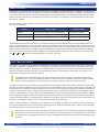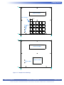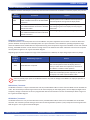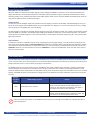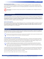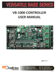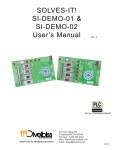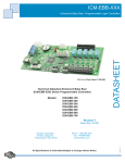
1
USER’S MANUAL
Revision: 0
Versatile Base 2X Series
VBDSP User Interface Board
Covered Models:
VBDSP-01
VBDSP-02
VBDSP-03
Divelbiss Corporation
9778 Mt. Gilead Road,
Fredericktown, Ohio 43019
Toll Free: 1-800-245-2327
Web: http://www.divelbiss.com
Email: [email protected]
2014003.0
Table of Contents
Manual Contents
Getting Started
How to Use this Manual........................................................................ 3
VBDSP-X Overview................................................................................. 4
Install / Mount the VBDSP-X.................................................................. 4
Configuring the VBDSP-X in EZ LADDER Toolkit..................................... 6
Getting to Know the VBDSP-X................................................................ 7
VBDSP-X Features
VBDSP-X Connections / Ports.............................................................. 10
LCD Display Features........................................................................... 12
LCD Display Heater.............................................................................. 12
User Programmable Features.............................................................. 13
Keypad Features.................................................................................. 13
VBDSP-X Specifications........................................................................ 14
WARNING!!
The VBDSP-X / VB-2XXX, as with other programmable controllers and peripherals must not
be used alone in applications which could be hazardous to personnel in the event of failure
of this device. Precautions must be taken by the user to provide mechanical and/or electrical
safeguards external to this device. This device is NOT APPROVED for domestic or human
medical use.
VBDSP-X User Manual
Document #: 2014003.0.pdf
Divelbiss Corporation • 9778 Mt. Gilead Road • Fredericktown, Ohio 43019 • 1-800-245-2327 • www.divelbiss.com
PAGE 1 of 14
Getting Started
This section explains how to read this manual and understand the symbols and information that it contains.
To begin using your VBDSP-X User Interface Board assembly you will need to follow these steps:
• Mount / Install the VB-2XXX Controller (sold separately)
• Mount the VBDSP-X board into the panel (will require pre-cut holes and mounting hardware).
• Connect the VBDSP-X board to the VB-2XXX controller using the provided ribbon cables (Keypad and
LCD port).
• Connect Power to the VBDSP-X board from the VB-2XXX controller or other power source using user
supplied wiring.
• Configure the VB-2XXX Controller to use the VBDSP-X in the EZ LADDER Toolkit Project Settings.
Refer to the appropriate sections of this manual for details on the above items.
Getting Started
How to Use this Manual
In this manual, the following conventions are used to distinguish elements of text:
BOLD
italic
SMALL CAPS
Denotes labeling, commands, and literal portions of syntax that must appear exactly as shown.
Used for variables and placeholders that represent the type of text to be entered by the user.
Used to show key sequences or actual buttons, such as OK, where the user clicks the OK button.
In addition, the following symbols appear periodically in the left margin to call the readers attention to specific details in the text:
Warns the reader of a potential danger or hazard associated with certain actions.
Appears when the text contains a tip that is especially useful.
Indicates the text contains information to which the reader should pay particularly close
attention.
All Specifications and Information Subject to Change without Notice
VBDSP-X User Manual
Document #: 2014003.0.pdf
Divelbiss Corporation • 9778 Mt. Gilead Road • Fredericktown, Ohio 43019 • 1-800-245-2327 • www.divelbiss.com
PAGE 3 of 14
Getting Started
VBDSP-X Overview
The VBDSP-X is an open-board user interface assembly with an LCD display and keyboard interface. The VBDSP-X is designed to be
panel mounted from the rear side of a panel door or mounted on faceplate that will be mounted in a panel door. The faceplate and/
or panel door will require pre-cut holes for the display, buttons and mounting hardware. The VBDSP-X is supplied with 36” ribbon
cables for the data connections to a VB-2XXX Series Controller (1 for display, 1 for keyboard). All mounting hardware and cut-outs
are customer supplied.
There are multiple models of VBDSP available. The size and type of LCD display and the number of push-buttons is determined by
the actual model number.
Model
LCD Size / Type
# of Push Buttons
VBDSP-01
2x16 LCD with Backlight, 3/8” Character Height
20 (5 Row x 4 Column)
VBDSP-02
4x20 LCD with Backlight, Standard Character Height
20 (5 Row x 4 Column)
VBDSP-03
2x16 LCD with Backlight, 3/8” Character Height
6 (2 Row x 3 Column)
The VBDSP-X display/keypad board connects to a VB-2XXX controller (model dependent) using two provided ribbon cables and
customer supplied wires for the power. The 20 conductor ribbon cable connects from the VB-2XXX controller’s DISPLAY port to the
VBDSP -X board’s DISPLAY port. The ribbon cable is keyed for proper polarity. The 10 conductor ribbon cable connects from the VB2XXX controller’s KEYPAD port to the VBDSP -X board’s KEYPAD port. The ribbon cable is keyed for proper polarity. Two individual
wires must connect the VB-2XXX controller’s DPWR port to the VBDSP-X board’s DPWR port. This wires are run from +VO to +VO
and
to . Two terminals are provided but only one must be connected.
Install / Mount the VBDSP-X
The VBDSP-X is designed to directly mount to the backside of a panel door or other sheet-metal that has been pre-cut and drilled
to accept the VBDSP-X. The VBDSP-X buttons come through pre-cut locations and the display and user programmble LEDs can be
viewed through pre-cut locations. The design of the VBDSP-X requires a sealing overlay be placed on the outside of the panel the
VBDSP-X is mounted to (with preset graphics and text identifying buttons and protecting the LCD window). The overlay is not included. All mounting hardware is customer supplied.
The VBDSP-X must be mounted using pre-cut holes. Detailed drawings of the cut-outs are available as download from www.divelbiss.com. The cut-out drawings provide hole sizes and cut-outs for the VBDSP-X only. PEMs or other mounting
hardware must be supplied for the actual mounting as hardware requirements will vary from panel to panel.
The VBDSP-X requires mounting hardware (not supplied) to mount the printed circuit board assembly to the panel. The mounting
hardware is customer supplied and must meet the requirements of the VBDSP-X and the hardware requirements of the panel itself.
The provided cut-out drawings are ideal for locations of the cut-outs for the push buttons and display. The VBDSP-X mounting hole
locations and hole sizes are shown. The panel’s mounting hole sizes will vary based on the type of panel (metal, fiberglass, etc.). It
is the user’s responsibility to correctly specify the mounting hole sizes and select appropriate hardware for mounting the VBDSP-X.
This may include having PEMs installed or drilling holes and using beveled hardware. The depth of the keypad is the critical dimension when selecting hardware. They keypad buttons should come through the panel door from the back side and be flush with the
panel front. The VBDSP-X is designed to be secured to 6-32 mounting studs or stand-offs.
Figure 1-1 are two sample cut-out drawings (one for VBDSP-01, one for VBDSP-03). Please note: one drawing shows individual cutouts for the keypad buttons while the other shows a single large cut-out. Both are acceptable cut-outs. Refer to the downloadable
CAD files from divelbiss.com for specfic measurements.
The depth of the keypad is the critical dimension when selecting hardware. They keypad buttons should come through the panel door from the back side and be flush with the panel front. Incorrect depth may cause keypad buttons to not function or multiple buttons to be triggered when one is pressed. The VBDSP-X is designed to be secured to 6-32 mounting studs or stand-offs.
VBDSP-X User Manual
Document #: 2014003.0.pdf
Divelbiss Corporation • 9778 Mt. Gilead Road • Fredericktown, Ohio 43019 • 1-800-245-2327 • www.divelbiss.com
PAGE 4 of 14
Getting Started
6.40
DISPLAY CUT-OUT
KEY CUT-OUTS
0.60
LED HOLES
0.00
7.30
0.00
6.40
DISPLAY CUT-OUT
LED HOLES
KEYPAD CUT-OUT
0.00
7.30
0.00
Figure 1-1 - Sample Cut-out drawings
VBDSP-X User Manual
Document #: 2014003.0.pdf
Divelbiss Corporation • 9778 Mt. Gilead Road • Fredericktown, Ohio 43019 • 1-800-245-2327 • www.divelbiss.com
PAGE 5 of 14
Getting Started
Refer to Figure 1-1. The cut-outs for the display and keypad (buttons) are shown. The holes for the user programmble LEDs are also
identified. The outside frame (square) is shown for reference of measurements and as an example of an overlay size to seal the
VBDSP-X into a panel. The remaining holes shown are all 6-32 mounting holes on the VBDSP-X board assembly. Theses holes require
the mounting hardware.
Divelbiss Corporation can provide an overlay design and actual overlays for your specific requirements. Contact us for details, pricing and delivery.
Configuring the VBDSP-X in EZ LADDER Toolkit
It is assumed that you are familiar with the VB-2XXX before installing this expansion option. Please refer to the VB-2XXX User
Manual for details regarding the VB-2XXX.
Before you can begin using features on the VBDSP-X, it must be configured as an option for the VB-2XXX target within the EZ LADDER Toolkit. For help with installing or using EZ LADDER, please refer to the P-Series EZ LADDER Toolkit Manual.
1. In EZ LADDER, from the File Menu at the top, click PROJECT then SETTINGS. This will open the Project Settings Window.
Select VB-2000 as the target from the choices. Refer to Figure 1-2.
Figure 1-2 - Project Settings Window
2. Click the PROPERTIES button to the right side of the window. The VB-2000 Properties Window will open. Make sure the
proper model is selected in the drop-down menu. If any expansion board was installed previously, it would be listed in
the Expansion Pane.
3. Highlight the User Interface Expansion in the list and click the PROPERTIES button on the right side of the Expansion pane in
the VB-2000 Properties Window. The User Interface Expansion Properties Window will open. Refer to Figure 1-3.
4. Select the appropriate VBDSP-X model from the list of Expansion boards. Refer to Figure 1-3. When you select a model, the
Details section of the window will update with the devices supported on the expander (for reference only) that will be
installed in the project settings of the program.
5. Click OK to accept the selected VBDSP-X and close the User Interface Expansion Properties Window.
6. Click OK to close the VB-2000 Properties window. Click OK to close the Project Settings window.
7. Save your ladder diagram using the menu FILE and SAVE or SAVE AS to save the current settings in your program.
The VBDSP-X is now installed in the ladder program project. The boolean variables for the Beeper, LCD backlight and user programmable LED are automatically installed as well as LCD display support.
VBDSP-X User Manual
Document #: 2014003.0.pdf
Divelbiss Corporation • 9778 Mt. Gilead Road • Fredericktown, Ohio 43019 • 1-800-245-2327 • www.divelbiss.com
PAGE 6 of 14
Getting Started
Figure 1-3 - User Interface Expansion Properties
Getting to Know the VBDSP-X
FRONT OF BOARD - REAR VIEW THROUGH PANEL
+VO
1
DISPLAY
11
HTRENABLE
F1
9
8
7
10
BEEPER
9
2
6
5
4
F3
+/-
3
2
1
F4
.
CLR
0
ENT
3
KEYPAD
F2
7
LED1
6
LED2
5
LED3
4
8
Figure 1-4 - VBDSP-X Features
VBDSP-X User Manual
Document #: 2014003.0.pdf
Divelbiss Corporation • 9778 Mt. Gilead Road • Fredericktown, Ohio 43019 • 1-800-245-2327 • www.divelbiss.com
PAGE 7 of 14
Getting Started
1. DPWR - Power Input from VB-2XXX
2. Heater Enable Switch
3. Keypad Button - # of buttons based on Model.
4. USER LED 3
5. USER LED 2
6. USER LED 1
VBDSP-X User Manual
7. KEYPAD Port (Connects to VB-2XXX)
8. 6-32 Mounting Holes x 8
9. Beeper
10. DISPLAY Port (Connects to VB-2XXX)
11. LCD display - rear view.
Document #: 2014003.0.pdf
Divelbiss Corporation • 9778 Mt. Gilead Road • Fredericktown, Ohio 43019 • 1-800-245-2327 • www.divelbiss.com
PAGE 8 of 14
VBDSP-X Features
This section explains the VBDSP-X hardware features, options and information regarding EZ LADDER Toolkit for basic operation.
VBDSP-X Features
VBDSP-X Connections / Ports
The VBDSP-X has three on-board ports (connectors) that need to be connected for the VBDSP-X to function properly. The ports are:
Port /
Connector
DPWR
Connection
Customer supplied wiring (2 conductors) from
VBDSP-X DPWR connection to VB-2XXX DPWR
connection.
Purpose
Provides power source to VBDSP-X board to operate onboard temperature sensing and LCD display heater.
DISPLAY
20 Conductor ribbon cable (included) connects Provides logic signals, backlight control and power and
from VBDSP-X DISPLAY connection to VB-2XXX user LED logic signals to LCD display and user programDISPLAY connection.
mable LEDs.
KEYPAD
10 Conductor ribbon cable (included) connects Provides logic signals and power for keypad operation.
from VBDSP-X KEYPAD connection to VB-2XXX
KEYPAD connection.
DPWR Port / Connector
The DPWR connector is the main power source for the VBDSP-X. The power supplied to this connector is used for on-board temperature detection and to power the LCD display heater. This port connection is not needed if the operating temperature range
where the VBDSP-X will be installed does not drop below freezing. If the temperature range of the installation is to be near or below
freezing, the DPWR connector must be wired to a voltage source of 12-24VDC for the heater and heater control circuits to operate
correctly. Refer to Figure 2-1 for a typical connection diagram.
Depending upon the actual temperature range of the installation for the VBDSP-X, the input voltage requirement may change.
Temperature Minumum
DPWR Voltage required
-30oC
12VDC Minimum is required.
-40oC
24VDC Minimum is required.
Reason
The LCD heater will operate well enough at 12VDC to
allow normal operation of the LCD display (slower response) at -30oC. Below this temperature, the heater is
not sufficient at 12VDC to allow operation.
The LCD heater will operate 24VDC to allow normal operation of the LCD display (slower response) at -40oC. The
LCD display is not rated to operate below -40oC.
Failure to provide proper power to the DPWR connector may result in damage to the VBDSP-X or improper operation at lower temperatures.
DISPLAY Port / Connector
The DISPLAY connector is a 20 pin connection that uses the provided ribbon cable to connect from the VBDSP-X to the VB-2XXX controller. This connection provides the logic control lines for the LCD display, the LCD display power, the LCD display backlight control
and power, the logic control lines for the user programmable LEDs and the control line for the on-board beeper. Refer to Figure 2-1
for a typical connection diagram.
KEYPAD Port / Connector
The KEYPAD connector is a 10 pin connection that uses the provided ribbon cable to connect from the VBDSP-X to the VB-2XXX
controller. This connection provides the logic control lines for the keypad matrix (columns / rows) and power for the keypad matrix.
Refer to Figure 2-1 for a typical connection diagram.
VBDSP-X User Manual
Document #: 2014003.0.pdf
Divelbiss Corporation • 9778 Mt. Gilead Road • Fredericktown, Ohio 43019 • 1-800-245-2327 • www.divelbiss.com
PAGE 10 of 14
+VO CTA CTB CTC
1
3
KEYPAD
2
SW5
DISPLAY
DISP
CONTRAST
OT0
OT1
OT2
OT3
OT4
OT5
OT6
OT7
ON
TX+ TX-
VB-2XXX
CONTROLLER
VBDSP-X Features
+VO
LED3
LED2
LED1
Ribbon Cable
Ribbon Cable
OT7 OT6 OT5 OT4 +VB OT3 OT2 OT1 OT0 +VA
ENT
CLR
.
F4
0
1
3
+/F3
2
4
6
F2
5
9
F1
8
7
KEYPAD
VBDSP-X
18 AWG WIRE
DISPLAY
+VO
Figure 2-1 - Typical Connections
VBDSP-X User Manual
Document #: 2014003.0.pdf
Divelbiss Corporation • 9778 Mt. Gilead Road • Fredericktown, Ohio 43019 • 1-800-245-2327 • www.divelbiss.com
PAGE 11 of 14
VBDSP-X Features
LCD Display Features
PRINTING TO THE LCD DISPLAY
When the VBDSP-X is installed in the ladder diagram project settings (the VBDSP-X is selected as a User Interface Expander), the
display functionality is automatically installed. The LCD display may be printed to using the LCD_PRINT function block and can be
cleared by using the LCD_CLEAR function block in the ladder diagram. Refer to the P-Series EZ LADDER Toolkit Manual for details on
using the LCD_PRINT and LCD_CLEAR function block.
LCD BACKLIGHT
The LCD port provides backlight Anode and Cathode for the LCD display connected. The VB-2000 / VB-2100 backlight circuit is preset for the actual displays on the VBDSP-X boards and is not adjustable. The displays use a current source and the current / voltage
used is typically not compatible with most LCD displays.
The LCD backlight is controlled in the ladder diagram program by the LCD_BL boolean variable. This variable is automatically created
when the VBDSP-X is installed in the VB-2000 Project Settings (the VBDSP-X is selected as a User Interface Expander). This variable
may be placed in the ladder diagram as a coil and controlled by a contact. When the boolean variable LCD_BL is true, then the backlight will be enabled.
LCD CONTRAST
The LCD Port provides an adjustable contrast circuit. As lighting and viewing angles change, it may be necessary to adjust the contrast of the connected LCD display. A DISPLAY CONTRAST potentiometer is provided. Refer to the VB-2XXX User Manual for thelocation of the LCD Contrast Potentiometer. To adjust the contrast, use a mini screw driver or potentiometer adjustment tool and turn
CONTRAST clockwise or counter-clockwise as necessary. CONTRAST is a multi-turn potentiometer and it may take several turns to
meet your contrast needs.
LCD Display Heater
The LCD display has a built-in heater. This heater is controlled by the circuitry on the VBDSP-X board. When the temperature drops
to near zero, the heater circuit automatically turns on the heater. When temperature rises above zero, the heater is turned off. A onboard temperature sensor is used to detect the changes in temperature.
The DPWR connector is the main power source for the VBDSP-X. The power supplied to this connector is used for on-board temperature detection and to power the LCD display heater. This port connection is not needed if the operating temperature range
where the VBDSP-X will be installed does not drop below freezing. If the temperature range of the installation is to be near or below
freezing, the DPWR connector must be wired to a voltage source of 12-24VDC for the heater and heater control circuits to operate
correctly.
Temperature Minumum
DPWR Voltage required
-30oC
12VDC Minimum is required.
-40oC
24VDC Minimum is required.
Reason
The LCD heater will operate well enough at 12VDC to
allow normal operation of the LCD display (slower response) at -30oC. Below this temperature, the heater is
not sufficient at 12VDC to allow operation.
The LCD heater will operate 24VDC to allow normal operation of the LCD display (slower response) at -40oC. The
LCD display is not rated to operate below -40oC.
Failure to provide proper power to the DPWR connector may result in damage to the VBDSP-X or improper operation at lower temperatures.
VBDSP-X User Manual
Document #: 2014003.0.pdf
Divelbiss Corporation • 9778 Mt. Gilead Road • Fredericktown, Ohio 43019 • 1-800-245-2327 • www.divelbiss.com
PAGE 12 of 14
VBDSP-X Features
LCD DISPLAY HEATER CONTROL
The LCD display heater may be disabled on the VBDSP-X if a reduction in power consumption is necessary, although the heater
circuit only operates when the temperature is near or below zero. SW1 (HTRENABLE) is used to enable or disable the LCD display
heater circuitry. The switch is marked with ‘ON’ and an arrow depicting the direction. The ON direction is with the switch set to the
center of the VBDSP-X.
The LCD display may not operate correctly at lower temperatures if the HTRENABLE switch is configured so the heater is set to disabled.
User Programmable Features
VBDSP-X LED CONTROL
When using the VB-2000 / VB-2100 with a VBDSP-X display board, there are up to 3 LED indicators available on the VBDSP-X board
that may be controlled and used in the ladder diagram as general purpose indicators in any way. When the VBDSP-X is configured in
EZ LADDER Toolkit, the LEDs are automatically installed and configured; the boolen variables for each are automatically created and
may be used in the program as necessary as coils or boolean variables. The LED indicators are DSPLED1, DSPLED2 and DSPLED3. The
variable names are the same ( DSPLED1, DSPLED2 and DSPLED3).
VBDSP-X BEEPER CONTROL
When using the VB-2000 / VB-2100 with a VBDSP-X display board, there is an on-board beeper (VBDSP-X). This beeper may be used
for any purose from within the ladder diagram. When the VBDSP-X is configured in EZ LADDER Toolkit, the BEEPER is automatically
installed and configured; the boolen variables is automatically created and may be used in the program as necessary as a coil or
boolean variable. The BEEPER uses the variable BEEP.
Keypad Features
The VBDSP-X provides up to 20 buttons in a keypad matrix (model dependent). When the VBDSP-X is configured in EZ LADDER Toolkit, keypad functionality is automatically installed and configured. The KEYPAD and KEYPAD2 function blocks in EZ LADDER Toolkit
are used to read numeric type inputs from the keypad matrix.
Although the KEYPAD and KEYPAD2 function blocks will operate with any VBDSP-X model. To gain the functionality of a full numeric input, the VBDSP-X must be a model with a full 20 button keyboard.
USING THE KEYPAD PORT IN EZ LADDER TOOLKIT
The Keypad (KEYPAD) port may be utilizied in the ladder diagram program (after it is installed) by using the KEYPAD and KEYPAD2
function blocks. These function blocks may be repeatedly placed in the ladder diagram as necessary to read keypad values. These
functions are typically used to read numbers such as 234 or 124.5 from the keypad into the ladder diagram as integer or real variables. Refer to the P-Series EZ LADDER Toolkit manual for more details using these function blocks.
In addition to reading complete values from the keypad, it is possible to read individual keys to determine if they are pressed. Each key has a predefined address that can be used as an input (boolean type variable that is classified as an
input). Create a contact as a new variable, and in the Var I/O Number field, enter the address of the specific key desired. When the key is pressed, the contact will be true.
The following addresses are used to read discrete keypad buttons. The numeric values are also provided for full 20 button keypad
functionality using the KEYPAD and KEYPAD2 function blocks. For reading the keypad button presses using boolean variables, you
must create a boolean variable for each button to be used as a boolean variable with the I/O Address (I/O Addr) shown. The ID
listed is the button identifier ID number silk screened onto the VBDSP-X.
Refer to the P-Series EZ LADDER Toolkit Manual for details on creating variables.
VBDSP-X User Manual
Document #: 2014003.0.pdf
Divelbiss Corporation • 9778 Mt. Gilead Road • Fredericktown, Ohio 43019 • 1-800-245-2327 • www.divelbiss.com
PAGE 13 of 14
VBDSP-X Features
I/O Addr.
KB_0
KB_1
KB_2
KB_3
KB_4
KB_5
KB_6
KB_7
KB_8
KB_9
Button Description
Numeric 0
Numeric 1
Numeric 2
Numeric 3
Numeric 4
Numeric 5
Numeric 6
Numeric 7
Numeric 8
Numeric 9
ID
PB17
PB11
PB12
PB13
PB6
PB7
PB8
PB1
PB2
PB3
I/O Addr.Button Description
KB_CLEAR
KB_DP
KB_+-
KB_F1
KB_F2
KB_F3
KB_F4
KB_UP
KB_DOWN
KB_ENTER
Clear Button
Decimal Point Button
+ / - Button
F1 Button
F2 Button
F3 Button
F4 Button
Up Button
Down Button
Enter Button
ID
PB18
PB19
PB14
PB5
PB10
PB15
PB20
PB4
PB9
PB16
VBDSP-X Specifications
Display Size:
Display Backlight:
Display Heater:
Display Contrast Adjust:
# of Buttons/Keys:
LEDs:
Beeper:
Operating Temp:
Dimensions:
Mounting:
Type:
Storage Temperature:
VBDSP-X User Manual
2 Row, 16 Column 3/8” tall character (VBDSP-01, VBDSP-03)
4 row, 20 Column Standard character size (VBDSP-02)
Yes, Controlled via ladder diagram
Yes, Automatically controlled. May be disabled by HTRENABLE switch
Yes, via adjustment potentiometer on VB-2XXX controller.
20 (4 Row, 5 Column)(VBDSP-01, VBDSP-02)
20 (2 Row, 3 Column)(VBDSP-03)
3 User Programmable via ladder diagram. (VBDSP-01/VBDSP-02)
2 User Programmable via ladder diagram. (VBDSP-03)
Yes, on-boad beeper/buzzer controlled via ladder diagram.
-30°C to 80°C (12VDC Input Power)
-40°C to 80°C (24VDC Input Power)
7.3” Wide x 6.4” Length x .1.7” Tall.
Panel Mount with 6-32 Hardware (not supplied)
Open Board
-40-85°C
Document #: 2014003.0.pdf
Divelbiss Corporation • 9778 Mt. Gilead Road • Fredericktown, Ohio 43019 • 1-800-245-2327 • www.divelbiss.com
PAGE 14 of 14