1
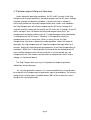
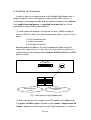
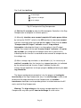
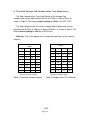
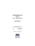
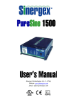
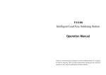
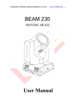
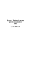
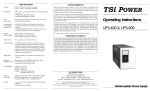
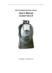
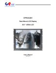
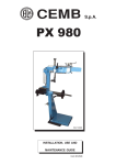
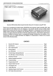
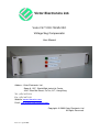
Victor Electronics Ltd.
Victor F47 120V-750VA VSC
Voltage Sag Compensator
User Manual
Address: Victor Electronics Ltd.,
Room 9, 13/F., World Wide Industrial Centre,
43-47 Shan Mei Street, Fo Tan, N.T., Hong Kong
Tel.: (852) 26871238
Fax: (852) 26871123
Website: www.victoronics.com
Email: [email protected]
Copyrights © 2009 Victor Electronics Ltd
All Rights Reserved.
Issue 4: 1 April 2009
Contents
1. Introduction ………………………………………………………...2
2. Principle of Operation ...…………………………………………..4
3. Technical Specifications (typical)...………………………..……..7
4. Protection against Abnormal Operation…………………………9
5. Simplified Test Procedure .………….…………………………..10
6. Threshold Voltage and Compensation Time Adjustments……12
Page1
1. Introduction
AC operated electronic equipment are vulnerable to momentary losses
of AC voltage, which are known as voltage sags. Voltage sags are commonly
caused by lightning, accidental short circuit, loose connection, starting of large
motors (or air-conditioners) or abnormal use of the AC mains. In sensitive and
critical applications, such as semiconductor material processing and medical
operation, voltage sags may result in serious problems. In order to tackle this
problem, the Semiconductor Equipment and Materials International (SEMI)
defined, in 1996, a voltage sag immunity standard, known as SEMI
F47-0200, for semiconductor processing equipment manufacturers to conform
to. Equipment compliant to this standard must have the specified immunity
characteristics against voltage sags without the use of batteries. Based on the
experience learned, the standard was redefined, in 2006, as SEMI F47-0706.
It is expected that new semiconductor processing equipment will be designed
to be compliant to the new standard. It is also likely that the SEMI F47-0706
requirement will be extended to other application areas.
Victor’s F47 Series of Voltage Sag Compensators have been
developed jointly by Victor Electronics and The Hong Kong Polytechnic
University to provide sine-wave AC backup power to enable electronic
equipment to meet the SEMI F47-0706 standard and to tolerate 100%
momentary loss of AC mains voltage (or momentary open circuit in the AC
line).
It should be noted that, although uninterruptible power supplies (UPS)
can be used to solve voltage sag problems in computers, it is not a suitable
solution for many applications due to the following reasons:
(1) A battery has to be used in a UPS. The acid, lead and other particles
from a battery can be harmful to the operating environment.
(2) The maintenance of the battery being used and the disposal of used
batteries can introduce problems.
(3) The output of a low-cost UPS is often a rectangular-wave voltage
(instead of a sine-wave voltage). This is undesirable for many
applications.
Page2
(4) There are often inductive loads in the electronic equipment. Normally
a low-cost UPS would not allow inductive loads.
(5) The slow transfer time of low-cost UPS may cause sensitive relays or
contactors to chatter.
In areas where UPS or batteries are not acceptable, Voltage Sag
Compensators can be used to minimize the undesirable effects of voltage
sags.
Page3
2. Principle of Operation
Fig. 1 shows a simplified schematic diagram of the Victor F47 Voltage Sag
Compensator.
Vac
SW
D1
D3
L1
Vo
Q3
Q1
V1
C3
C1
D5
Boost Regulator
High-side Driver
Load
L3
C5
Q2
C2
C4
Q4
Boost Regulator
Low-side Driver
D6
D2
D4
L2
Inverter
High-side Driver
Microcomputer
Controller
Inverter
Low-side
Driver
Fig.1 Simplified schematic diagram of Victor F47 Sag Compensator
In Fig. 1, D1 and C1 form a rectifier to provide positive power supply to the
positive boost regulator composed of L1, Q1, D3, and C3. D2 and C2 form a
rectifier to provide negative power supply to the negative boost regulator
composed of L2, Q2, D4, and C4. Q3, Q4, D5, D6, L3, and C5 (together with
the related drivers) form a DC to AC inverter. The Microcomputer Controller
monitors the AC mains and controls the operation of the DC to AC inverter.
During normal operation the AC mains is connected to the load through
the relay switch SW. The Inverter High-side and Low-side Drivers of the DC to
AC inverter are disabled, so that the inverter output transistors Q3 and Q4 are
turned off.
When a voltage sag in the AC mains is detected by the Microcomputer
Controller, the relay switch SW is opened. The DC to AC Inverter is then
Page4
enabled to generate a back up AC voltage (sine-wave) for a preset period of
time (adjustable from 0.25s to 2s). Within this period, the Inverter provides
sine-wave AC power to the load.
At the end of the preset period (nominally preset to 2s), the inverter is
disabled and the microcomputer switches the load back to the AC mains.
In Victor F47 Voltage Sag Compensators, the following new technologies
have been developed to minimize the adverse effects of voltage sags:
(1) The technology of storing up energy in large capacitors and, when
there is a sag in the AC mains, converting most of the stored energy to
AC back-up power.
(2) The technology of using a microcomputer controller to fast detect the
occurrence of voltage sag and to control the operation of the DC to AC
(sine-wave) inverter.
(3) The technology of fast switching the load between the AC mains and
the DC to AC inverter, while maintaining practically zero conduction loss
during normal operation.
(4) The technology of minimizing the chattering of AC relays/contactors
in the loading circuit using software techniques.
It should be noted that a very important task of the sag compensator is to
ensure that the operation of AC relays/contactors in the loading circuit will not
be affected by the transfer operation between the AC mains and the DC to AC
inverter during the voltage sag period. It is well known that the transfer
operation often results in chattering of contacts. Chattering can be minimized
by reducing the transfer time. However, our study indicates that if the software
that drives the AC to DC inverter is designed properly the relay/contactor can
tolerable a much slower transfer time without chattering. In other words,
chattering can be efficiently minimized by software.
In order to design proper software to reduce the chance of chattering, it is
necessary to understand the dynamic behavior of relays/contactors. However
such behaviors of AC relays/contactors under transient conditions (during the
Page5
transfer operation) are difficult to analyze because of the following reasons:
(1) In order to ensure that the energized solenoid will not drop out during
the zero-crossing region of the AC driving current, the solenoid of an AC
relay/contactor is split into two halves. On half of it has effectively a
one-turn short-circuit secondary winding. This makes the analysis of the
transient behaviors of AC relays/contactors complex.
(2) The energizing coil of AC relay/contactor is inductive and the exact
current waveform of the effective energizing current of the solenoid under
transient condition is difficult to determine.
In the design of the voltage sag compensator, extensive computer
simulations have been used in Victor Electronics to analyze the behaviors of
AC relays/contactors and to tailor-make software to minimize chattering during
transfer periods.
Page6
3. Technical Specifications (typical)
Nominal AC Input Voltage: 120V
Maximum AC Input Voltage: 132V
Input Frequency: 50/60 Hz, auto-sensing
Output Capacity: 750VA
Voltage Drop due to Compensator (full load) : < 0.5V
Efficiency: 99% at full load (under no voltage sag condition)
Full Load Current:
6.25A (The load can be resistive, capacitive, or inductive.)
Inrush Current: 50A
Ride-through Time:
(1) Exceeds the SEMI F47-0706 standard, which is shown in Table 1.
Sag depth*
Duration at
50Hz
Duration at
60Hz
Time
50%
10 cycles
12 cycles
0.2 second
70%
25 cycles
30 cycles
0.5 second
80%
50 cycles
60 cycles
1 second
Table 1 SEMI F47-0706 Standard
*Sag depth is expressed in percent of remaining nominal voltage.
For example, a sag depth of 80% for 120V AC means that the
voltage is reduced to 96V.
(2) Even under the condition of zero AC input voltage or
open-circuited input, meets the ride-through time requirement of
one second minimum at full load with load power factor of 0.25.
Page7
Voltage Sag Compensation Response Time:
4 milliseconds (including detection time)
Sag Compensation Threshold Voltage:
Adjustable from 85V to 115V in steps of 5V; factory preset to 100V.
(See Paragraph 6 for details.)
Sag Compensation Time:
Adjustable from 0.25s to 2s in steps of 0.25s; factory preset to 2s.
(See Paragraph 6 for details.)
Waveform of Output Voltage:
Sine-wave, with Total Harmonic Distortion < 8%
Fail Safe Mode:
The unit will not drop the load in the event the DC to AC inverter in
the unit fails.
Recharge Time (for the energy storage capacitors to charge up
again): 3 seconds
Indicators:
AC Mains Input (green), Compensator AC Output (amber), and
Inverter Output (red)
Output voltage variation (for the range of Operating AC Input
Voltage from 105V to 125V and load variation from no load to full
load): 105V to 125V
Page8
4. Protection against Abnormal Operation
Under abnormal operating conditions, the DC to AC inverter in the Sag
Compensator may be repetitively started to compensate the AC mains voltage.
A typical example of abnormal condition is that the AC mains voltage is
consistently below the threshold compensation level. Under such condition,
the Sag Compensator will initially compensate the AC mains voltage for 2
seconds and then reconnect the load to the AC mains for 3 seconds. If the AC
mains voltage is then still below the threshold compensation level, the
compensator will begin another cycle of “2-second compensation followed by
3-second back to the AC mains”. However, if the repetitive rate of the
compensation cycle is more than 4 times in every minute, the Sag
Compensator may enter a protective mode operation. Under this mode of
operation, the sag compensator will stop the compensation operation for 2
minutes, waiting the heat-generating components in the Sag Compensator to
cool down. Within this 2-minute period, the load will be connected to the AC
mains without compensation. At the end of the 2-minute period, the sag
compensator will start another round of effort to compensate the AC mains
voltage, as mentioned above.
The Sag Compensator can stay in the protective mode of operation
indefinitely without damage.
As a further protective measure, it is recommended that a circuit breaker
be used with the Compensator for protection against overloading. The current
rating of the circuit breaker should be about 150% of the maximum current
rating of the sag Compensator.
Page9
5. Simplified Test Procedure
In order to fully test the performance of the Voltage Sag Compensator, a
programmable AC source (with galvanic isolation from the AC mains), an
oscilloscope, and a programmable load are required. However, even without
such sophisticated equipment, a simplified functional test can still be
performed through the following procedures:
(1) Under power-off condition, connect the AC mains (120V) through an
external ON/OFF switch to the Sag Compensator, which is shown in Fig. 2,
where
G is the Ground terminal
L is the Live terminal
N is the Neutral terminal
Do not confuse the live line (L) with the neutral line (N) from the AC
mains. For simple testing, it is not necessary to connect any load to the
output terminal of the Compensator. Keep the ON/OFF switch in the OFF
position initially.
INPUT OUTPUT
G L N N L G
ON
1
ON
2
3
1
2
3
Compensation Time
Selector
Threshold Voltage
Selector
Fig. 2 Rear panel of Sag Compensator
(2) After checking the circuit, turn the ON/OFF switch to the ON position.
The green “AC Mains Input” indicator and the amber “Compensator AC
Output” indicator on the front panel of the Sag Compensator, as shown in
Page10
Fig. 3, will then be lit up.
AC Mains Input
Compensator AC Output
Inverter Output
Fig. 3 Front panel of Sag Compensator
(3) Wait for 10 seconds to allow the Microcomputer Controller in the Sag
Compensator to complete its initiation process.
(4) Manually simulate a one-second complete AC mains power failure
by turning the ON/OFF switch to the OFF position for about one second,
and then returning it back to the on position again. Check that the amber
“Compensator AC Output” indicator remains lit up without
interruption, indicating that there is no interruption in the AC output
voltage. Also check that the red “Inverter Output” indicator is lit up for
two seconds (assuming that the compensation time is preset to 2s),
indicating that the Inverter has worked for two seconds to compensate for
the voltage sag.
(5) After a voltage sag simulation, as described in (4), it is necessary to
wait for 3 seconds after the Inverter has stopped operation (as indicated
by the extinguished red “Inverter Output” indicator) to allow the
energy-storage capacitors to charge up again, before performing the next
sag simulation.
The above-mentioned test procedure is for the purpose of testing the
functionality of the Sag Compensator only. If an oscilloscope is to be used
to observe the output waveform of the Compensator, an isolation
transformer should be used to provide galvanic insulation between the AC
mains and the Sag Compensator.
Warning: The high voltage on the energy-storage capacitors in the
Compensator may take up to 1 hour to discharge to a safe value.
Page11
6. Threshold Voltage and Compensation Time Adjustments
The Sag Compensation Threshold Voltage of the Voltage Sag
Compensator can be adjusted from 85Vac to 115Vac in steps of 5Vac, as
shown in Table 2. The factory default setting is 100Vac (ON-OFF-OFF).
The Sag Compensation Time of the Voltage Sag Compensator can be
adjusted from 0.25sec to 2.00sec in steps of 0.25sec, as shown in Table 3. The
factory default setting is 2.00 sec (ON-ON-ON).
Warning: Turn off the power when changing the positions of the selector
switches.
Threshold Voltage Selector
(SW1)
VTH
Compensation Time Selector
(SW2)
SW1_1 SW1_2 SW1_3
TCOMP
SW2_1
SW2_2
SW2_3
115Vac
ON
ON
ON
*2.00s
ON
ON
ON
110Vac
ON
ON
OFF
1.75s
ON
ON
OFF
105Vac
ON
OFF
ON
1.50s
ON
OFF
ON
*100Vac
ON
OFF
OFF
1.25s
ON
OFF
OFF
95Vac
OFF
ON
ON
1.00s
OFF
ON
ON
90Vac
OFF
ON
OFF
0.75s
OFF
ON
OFF
85Vac
OFF
OFF
ON
0.50s
OFF
OFF
ON
100Vac
OFF
OFF
OFF
0.25s
OFF
OFF
OFF
* Factory default setting
Table 2 Threshold Voltage Selector
* Factory default setting
Table 3 Compensation Time Selector
-ENDPage12