1
K R A ME R E LE CT R O N IC S L TD .
USER MANUAL
MODEL:
VP-444
Presentation Switcher/Scaler
P/N: 2900-300305 Rev 3
Contents
1
Introduction
1
2
2.1
2.2
2.3
3
3.1
Getting Started
Achieving the Best Performance
Safety Instructions
Recycling Kramer Products
Overview
Defining the VP-444 Presentation Switcher/Scaler
2
2
3
3
4
5
4
Installing in a Rack
8
5
5.1
5.2
Connecting the VP-444
Connecting the Balanced Stereo Audio Output
Microphone Pinout
9
11
11
6
6.1
6.2
6.3
6.4
6.5
7
7.1
7.2
7.3
7.4
7.5
7.6
7.7
7.8
7.9
8
8.1
8.2
Controlling the VP-444
Controlling via the Front Panel Buttons
Using the OSD Menu
Connecting to the VP-444 via RS-232
Operating via Ethernet
Controlling via the Infrared Remote Control Transmitter
Using the Embedded Web Pages
Browsing the VP-444 Web Pages
The Input Select Page
The Device Settings Page
The Output Settings Page
The HDCP Page
The EDID Page
The Audio Settings Page
The Advanced Page
The About Page
Technical Specifications
Default Communication Parameters
Input Resolutions
12
12
12
15
15
19
20
21
22
24
26
27
28
31
31
32
33
34
34
9
9.1
9.2
9.3
The RS-232/Ethernet (UDP) Communication Protocol
Kramer Protocol 3000 Syntax
Kramer Protocol 3000 – Command List
Kramer Protocol 3000 – Detailed Commands
35
35
38
39
VP-444 – Contents
i
Figures
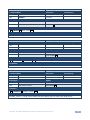
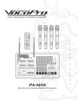
Figure 1: VP-444 Presentation Switcher/Scaler Front Panel
Figure 2: VP-444 Presentation Switcher/Scaler Rear Panel
Figure 3: Connecting the VP-444 Presentation Switcher / Scaler
Figure 4: Connecting the Balanced Stereo Audio Output
Figure 5: Connecting an Unbalanced Stereo Audio Acceptor to the Balanced Output
Figure 6: Condenser Microphone Pinout
Figure 7: Dynamic Microphone Pinout
Figure 8: Local Area Connection Properties Window
Figure 9: Internet Protocol Version 4 Properties Window
Figure 10: Internet Protocol Version 6 Properties Window
Figure 11: Internet Protocol Properties Window
Figure 12: Infrared Remote Control Transmitter
Figure 13: The Input Select Page
Figure 14: Edit Input Buttons
Figure 15: The Device Settings Page
Figure 16: The Device Settings Page – Static IP Confirmation.
Figure 17: The Device Settings Page – Uploading the New Firmware File
Figure 18: The Device Settings Page – Uploading the New Firmware File
Figure 19: The Device Settings Page – New Firmware Updated
Figure 20: The Output Settings Page
Figure 21: The HDCP Page
Figure 22: The EDID Page
Figure 23: The EDID Page – Copying the Default
Figure 24: The EDID Page –The Copy EDID Results
Figure 25: The Audio Settings Page
Figure 26: The Advanced Page
Figure 27: The About Page
ii
6
7
10
11
11
11
11
16
17
17
18
19
22
23
24
24
25
25
26
26
27
28
29
30
31
32
32
VP-444 - Introduction
1 Introduction
Welcome to Kramer Electronics! Since 1981, Kramer Electronics has been
providing a world of unique, creative, and affordable solutions to the vast range of
problems that confront video, audio, presentation, and broadcasting professionals
on a daily basis. In recent years, we have redesigned and upgraded most of our
line, making the best even better!
Our 1,000-plus different models now appear in 14 groups that are clearly defined by
function: GROUP 1: Distribution Amplifiers; GROUP 2: Switchers and Routers;
GROUP 3: Control Systems; GROUP 4: Format/Standards Converters; GROUP 5:
Range Extenders and Repeaters; GROUP 6: Specialty AV Products; GROUP 7:
Scan Converters and Scalers; GROUP 8: Cables and Connectors; GROUP 9:
Room Connectivity; GROUP 10: Accessories and Rack Adapters; GROUP 11:
Sierra Video Products; GROUP 12: Digital Signage; GROUP 13: Audio; and
GROUP 14: Collaboration.
Congratulations on purchasing your Kramer VP-444 Presentation Switcher/Scaler.
This product, which incorporates HDMI™ technology, is ideal for:
Projection systems in conference rooms, boardrooms, hotels and churches
Home theater up-scaling
VP-444 – Introduction
1
2 Getting Started
We recommend that you:
Unpack the equipment carefully and save the original box and packaging
materials for possible future shipment
i
2.1
Review the contents of this user manual
Go to http://www.kramerelectronics.com/support/product_downloads.asp
to check for up-to-date user manuals, application programs, and to check
if firmware upgrades are available (where appropriate).
Achieving the Best Performance
To achieve the best performance:
Use only good quality connection cables (we recommend Kramer highperformance, high-resolution cables) to avoid interference, deterioration in
signal quality due to poor matching, and elevated noise levels (often
associated with low quality cables)
Do not secure the cables in tight bundles or roll the slack into tight coils
Avoid interference from neighboring electrical appliances that may adversely
influence signal quality
Position your Kramer VP-444 away from moisture, excessive sunlight and
dust
!
2
This equipment is to be used only inside a building. It may only be
connected to other equipment that is installed inside a building.
VP-444 - Getting Started
2.2
Safety Instructions
!
2.3
Caution:
There are no operator serviceable parts inside the unit
Warning:
Use only the power cord that is supplied with the unit
Warning:
Do not open the unit. High voltages can cause
electrical shock! Servicing by qualified personnel only
Warning:
Disconnect the power and unplug the unit from the wall
before installing
Recycling Kramer Products
The Waste Electrical and Electronic Equipment (WEEE) Directive 2002/96/EC aims
to reduce the amount of WEEE sent for disposal to landfill or incineration by
requiring it to be collected and recycled. To comply with the WEEE Directive,
Kramer Electronics has made arrangements with the European Advanced
Recycling Network (EARN) and will cover any costs of treatment, recycling and
recovery of waste Kramer Electronics branded equipment on arrival at the EARN
facility. For details of Kramer’s recycling arrangements in your particular country go
to our recycling pages at http://www.kramerelectronics.com/support/recycling/.
VP-444 – Getting Started
3
3 Overview
The VP-444 is a high−performance presentation scaler/switcher for HDMI and
computer graphics signals. The unit scales the video, embeds the audio, and
outputs the signal to two HDMI (with embedded audio) outputs (with S/PDIF and
balanced stereo audio) simultaneously.
The VP-444 features:
PixPerfect™ scaling technology – Kramer’s precision pixel mapping and
high quality scaling technology. High-quality 3:2 and 2:2 pull down deinterlacing and full up and down scaling of all video input signals
HDTV compatibility
HDCP compliance - The HDCP (High Definition Content Protection) license
agreement allows copy−protected data on the HDMI input to pass only to the
HDMI outputs
12 video inputs - 10 HDMI on HDMI connectors, 2 computer graphics video
on 15−pin HD connectors
Two HDMI scaled outputs
Up to UXGA/1080p output resolutions
Two microphone inputs that can be used by mixing, switching or talk-over
Companion AFV (Audio-Follow-Video) - stereo audio for every input (on
terminal blocks)
12 unbalanced stereo inputs on terminal blocks as well as embedded audio
for the HDMI inputs, each with individual level controls
Audio outputs – one S/PDIF on an RCA connector, one balanced stereo
audio on a terminal block as well as embedded audio on the HDMI outputs
Multiple aspect ratio selections - full, best fit, over scan, under scan, letter
box and pan scan
Powerful audio features via DSP technology including audio equalization,
mixing, delay and so on
4
Built-in ProcAmp - color, hue, sharpness, noise, contrast and brightness
VP-444 - Overview
Supports 4:4:4 (RGB and YUV) as well as 4:4:2 (YUV) color sampling
Maintains constant output sync – there is no disruption on the output while
switching between inputs and when no video is detected
Front panel control - audio mute and freeze frame
Front panel lockout
Non-volatile memory - saves final settings
Control your VP-444:
Directly, via the front panel push buttons
By RS-232 serial commands transmitted by a touch screen system, PC, or
other serial controller
Remotely, from the infrared remote control transmitter with OSD (on-screen
display)
Via the Ethernet with built-in Web pages
The VP-444 is housed in a 19” 1U rack mountable enclosure, with rack “ears”
included, and is fed from a 100-240 VAC universal switching power supply.
3.1
Defining the VP-444 Presentation Switcher/Scaler
This section defines the VP-444.
VP-444 – Overview
5
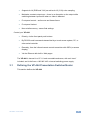
6
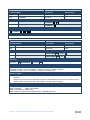
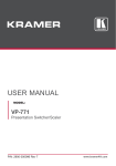
Figure 1: VP-444 Presentation Switcher/Scaler Front Panel
Feature
Function
1
#
IR LED
Lights when the unit accepts IR remote commands
2
IR Receiver
3
4
INPUT Selector
Buttons
5
FREEZE Button
Press to freeze/unfreeze the output video image; can be programmed to follow MUTE (see Section 6.2.1)
6
MUTE Button
Press to toggle between muting (blocking out the sound) and enabling the audio output
7
MENU Button
8
Navigation Buttons
Receives signals from the remote control transmitter
HDMI
PC
Press to select the HDMI input (from 1 to 10)
Press to select the computer graphics input (from 1 to 2)
Displays the OSD menu (see Section 6.2)
Press to decrease numerical values or select from several definitions
When not within the OSD menu mode, press to reduce the output volume
Press to move up the menu list values (see Section 6.2)
Press to increase numerical values or select from several definitions
When not within the OSD menu mode, press to increase the output volume
Press to move down the menu list (see Section 6.2)
ENTER
Press to accept changes and change the SETUP parameters (see Section 6.2)
9
RESET TO XGA/720p Button
Press to reset the video resolution to XGA or 720p
Press and hold for about 5 seconds to toggle between switching to XGA or 720p
10
PANEL LOCK Button
Press and hold for about 5 seconds to lock/unlock the front panel buttons
VP-444 – Overview
VP-444 – Overview
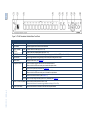
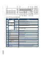
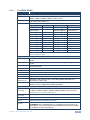
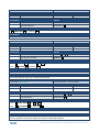
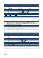
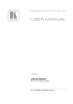
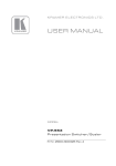
Figure 2: VP-444 Presentation Switcher/Scaler Rear Panel
#
11
Feature
Function
VIDEO INPUT
Connectors
HDMI
Connect to the HDMI source (from 1 to 10)
PC 15-pin HD
Connect to the computer graphics source (from 1 to 2)
HDMI
Connect to the analog audio HDMI source (from 1 to 10)
14
AUDIO INPUT Unbalanced
Stereo Terminal Blocks
PC
Connect to the analog audio computer graphics source (from 1 to 2)
15
AUDIO OUTPUTS
Balanced Stereo
Terminal Block
Connects to the balanced stereo analog audio acceptor
S/PDIF 3.5 Mini
Jack Connector
Connects to a digital audio acceptor
12
13
16
17
Mains Socket
Connect the mains power cord
18
Mains Fuse Holder
Fuse for protecting the device
19
Power Switch
Switch for turning the unit ON or OFF
20
HDMI OUT 1
Connect to the HDMI acceptor 1
21
HDMI OUT 2
Connect to the HDMI acceptor 2
22
COND / DYN Switch for MIC 1
Move up to select a condenser type microphone; down to select a dynamic type microphone
23
MIC 1 6mm Jack
Connect to the microphone source 1
24
COND / DYN Switch for MIC 2
Move up to select a condenser type microphone; down to select a dynamic type microphone
25
MIC 2 6mm Jack
Connect to the microphone source 2
26
RS-232 9-pin D-sub Port
Connect to the PC or the remote controller
27
PROG
For factory use only
28
ETHERNET Connector
Connects to the PC or other Serial Controller through computer networking
7
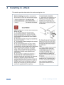
4 Installing in a Rack
This section provides instructions for rack mounting the unit.
8
VP-444 - Installing in a Rack
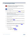
5 Connecting the VP-444
!
Always switch off the power to each device before connecting it to
your VP-444. After connecting your VP-444, connect its power and
then switch on the power to each device.
i
You do not have to connect all the inputs and outputs, connect only
those that are required.
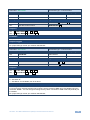
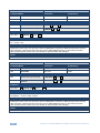
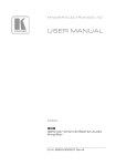
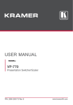
To connect the VP-444, as illustrated in the example in Figure 3, do the following:
1. Connect an HDMI source (for example, a BluRay disk player) to the HDMI
VIDEO INPUT connector (from 1 to 10).
Alternatively, you can connect the DVI connector on the DVD player to the HDMI
connector on the VP-444 via a DVI-HDMI adapter. When using this adapter, you can
connect the audio signal via the terminal block connector
2. Connect a computer graphics source to the PC 1 15-pin HD VIDEO INPUT
connector (from 1 to 2).
3. Connect the audio input signals to the AUDIO IN terminal block connectors,
as required (not shown in Figure 3).
4. Connect the HDMI OUT 1 connector to an HDMI acceptor (for example, an
LCD display), from 1 to 2.
5. Connect the audio output signals to the OUT stereo analog audio acceptor
and/or the digital audio acceptor, as required (not shown in Figure 3).
6. Connect the power cord (not shown in Figure 3).
7. If required, connect:
A PC via RS-232, see Section 6.3
The ETHERNET port, see Section 6.4
VP-444 - Connecting the VP-444
9
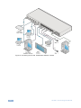
Figure 3: Connecting the VP-444 Presentation Switcher / Scaler
10
VP-444 - Connecting the VP-444
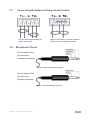
5.1
Connecting the Balanced Stereo Audio Output
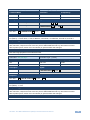
Figure 4: Connecting the Balanced
Stereo Audio Output
5.2
Figure 5: Connecting an Unbalanced Stereo
Audio Acceptor to the Balanced Output
Microphone Pinout
The microphone 6mm
jack pinout for a
condenser microphone.
Figure 6: Condenser Microphone Pinout
The microphone 6mm
jack pinout for a
Dynamic microphone.
Figure 7: Dynamic Microphone Pinout
VP-444 - Connecting the VP-444
11
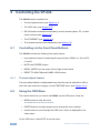
6 Controlling the VP-444
The VP-444 can be controlled via:
The front panel buttons (see Section 6.1)
The OSD menu (see Section 6.2)
RS-232 serial commands transmitted by a touch screen system, PC, or other
serial controller (see Section 6.3)
6.1
The ETHERNET (see Section 6.4)
The infrared remote control transmitter (see Section 6.5)
Controlling via the Front Panel Buttons
The VP-444 includes the following front panel buttons:
Input selector buttons for selecting the required input: HDMI (1 to 10) and PC
(1 and 2)
6.1.1
MUTE and FREEZE buttons
MENU, ENTER, and up, down, left and right arrow buttons
RESET TO XGA/720p and PANEL LOCK buttons
The Auto Adjust Feature
The auto adjust feature is implemented every time the input is switched to VGA or
when the input resolution changes, via the FINETUNE menu (see Section 6.2.1).
6.2
Using the OSD Menu
The control buttons let you control the VP-444 via the OSD menu. Press the:
MENU button to enter the menu
The default timeout is set to 10 seconds
ENTER button to accept changes and to change the menu settings
Arrow buttons to move through the OSD menu, which is displayed on the
video output
On the OSD menu, select EXIT to exit the menu.
12
VP-444 - Controlling the VP-444
6.2.1
The MAIN MENU
Mode
Function
OUTPUT
SOURCE:
Select the input: HDMI 1, HDMI 2, HDMI 3, HDMI 4, HDMI 5, HDMI 6,
HDMI 7, HDMI 8, HDMI 9, HDMI 10, PC1 or PC2
SIZE:
Select the image size: FULL, OVER SCAN, UNDER 1, UNDER 2, LETTER
BOX, PAN SCAN or BEST FIT
RESOLUTION:
Select the output resolution from the menu:
Output resolution:
Output resolution:
Appears as:
NATIVE OUT1
Appears as:
1680x1050 @60Hz
1680x1050 60
NATIVE OUT2
1600x1200 @60Hz
1600x1200 60
640x480 @60Hz
640x480 60
1920x1080 @60Hz
1920x1080 60
800x600 @60Hz
800x600 60
1920x1200 @60Hz
1920x1200 60
1024x768 @60Hz
1024x768 60
480p @60Hz
720x480P 60
1280x768 @60Hz
1280x768 60
720p @60Hz
1280x720P 60
1360x768 @60Hz
1360x768 60
1080i @60Hz
1920x1080I 60
1280x720 @60Hz
1280x720 60
1080p @60Hz
1920x1080P 60
1280x800 @60Hz
1280x800 60
576p @50Hz
720x576P 50
1280x1024 @60Hz
1280x1024 60
720p @50Hz
1280x720P 50
1440x900 @60Hz
1440x900 60
1080i @50Hz
1920x1080I 50
1400x1050 @60Hz
1400x1050 60
1080p @50Hz
1920x1080P 50
NATIVE - Select NATIVE to select the output resolution from the EDID of the
connected HDMI monitor
PICTURE
CONTRAST:
Set the contrast (the range and default values vary according to the input
signal)
BRIGHTNESS:
Set the brightness (the range and default values vary according to the input
signal)
RED
Set the red shade
GREEN
Set the green shade
BLUE
Set the blue shade
HUE
Set the color hue (not applicable for VGA inputs)
SATURATION
Set the color saturation (not applicable for VGA inputs)
SHARPNESS
Set the sharpness of the picture (not applicable for VGA inputs)
NOISE
REDUCTION
Select the noise reduction: OFF, LOW, MID (middle) and HIGH (not
applicable for VGA inputs)
FINETUNE
Enabled for VGA: AUTO ADJUST (NO/YES), H-POSITION, V-POSITION,
PHASE, CLOCK, WXGA/XGA, RESET (NO/YES)
AUDIO
INPUT
VOLUME:
Set the volume separately for each input: HDMI 1, HDMI 2, HDMI 3, HDMI
4, HDMI 5, HDMI 6, HDMI 7, HDMI 8, HDMI 9, HDMI 10, PC1 and PC2
Not applicable for embedded HDMI inputs
OUTPUT
VOLUME:
Set the output volume
DELAY
Select the audio delay time: OFF, 40ms, 110ms and 150ms
MUTE
Select the sound mute options: ON, OFF
EMBEDDED
AUDIO:
Select the audio source of the HDMI 1 to HDMI 10 inputs:
AUTOMATIC: the embedded audio on the HDMI input is selected for an
HDMI signal, or the analog audio input is selected if the input is not HDMI
(for example, for a DVI input signal)
VP-444 - Controlling the VP-444
13
Mode
Function
EMBEDDED: the embedded audio in the HDMI signal is selected
ANALOG: the analog audio input is selected
MIXER:
Set to OFF to disable mixing of the microphone with the audio output, MIC1, MIC2
or both to mix either MIC 1, MIC 2 or both microphones with the audio output
MIC VOLUME
Set the microphone volume for MIC1 and MIC2
ADVANCED
HDCP ON
INPUT
Select the HDCP option for the HDMI input: either ON (the default) or OFF.
Setting HDCP support to enabled (ON) on the HDMI input allows the
source to transmit a non-HDCP signal if required (for example, when
working with a Mac computer)
HDCP ON
OUTPUT
Set HDMI OUT1 and HDMI OUT2:
AUTO SYNC
OFF
Turn to OFF, FAST (for almost immediate shut down if no input is present –
about 10 seconds) or SLOW (for shutdown after about 2 minutes).
This is useful, for example, when the output is connected to a projector, and the
projector will automatically shut down when it has no input
OSD
H POSITION
Set the horizontal position of the OSD
V POSITION
Set the vertical position of the OSD
TIMER
Set the timeout period in seconds
TRANSPARENCY
Set the OSD background between 100 (transparent)
and 0 (opaque)
Select FOLLOW INPUT or FOLLOW OUTPUT to define whether the
HDCP will follow the input or the output
When FOLLOW INPUT is selected, it changes its HDCP output setting (for
the HDMI output) according to the HDCP of the input. This option is
recommended when the HDMI output is connected to a splitter/switcher
When FOLLOW OUTPUT is selected, the scaler matches its HDCP output
to the HDCP setting of the HDMI acceptor to which it is connected
DISPLAY
MUTE
FOLLOWS
FREEZE
MUTE BUTTON
DEFINE:
AUTO
SWITCHING
Select the information shown on the screen during
operation:
INFO: the information is shown for 10 seconds
ON: the information is shown permanently
OFF: the information is not shown
Set to ON to have MUTE follow FREEZE. Otherwise set to OFF
Define the MUTE button to function as MUTE, BLANK or BLANK AND
MUTE
MODE
Set the auto switching mode to OFF, AUTO SCAN or
LAST CONNECTED. PRIORITY (below) is enabled
when AUTO SCAN is selected
When one of the auto switching modes is selected (AUTO
SCAN or LAST CONNECTED), audio is enabled only
when a video signal is detected
ETHERNET
SCAN PRIORITY
Set to HDMI to begin scan with HDMI1 or to PC to
begin scan with PC1
IP MODE
Set the IP mode to DHCP or STATIC IP
STATIC IP ADDRESS (fill in if STATIC IP (above) is selected:
14
IP ADDRESS
Enter the IP address
SUBNET
Enter the subnet
GATEWAY
Enter the gateway
CONTROL PORT
Enter the control port
MAC ADDRESS
MAC address
VP-444 - Controlling the VP-444
Mode
Function
FACTORY RESET
Select NO or YES
INFORMATION
Displays the INPUT RESOLUTION, the OUTPUT RESOLUTION, INPUT
HDCP (HDCP/NONE), OUTPUT 1/2 HDCP (HDCP/NONE) VERSION and
the IP ADDRESS
6.3
Connecting to the VP-444 via RS-232
You can connect to the VP-444 via an RS-232 connection using, for example, a PC.
Note that a null-modem adapter/connection is not required.
To connect to the VP-444 via RS-232, connect the RS-232 9-pin D-sub rear panel port
on the product unit via a 9-wire straight cable (only pin 2 to pin 2, pin 3 to pin 3, and pin
5 to pin 5 need to be connected) to the RS-232 9-pin D-sub port on your PC
6.4
Operating via Ethernet
You can connect to the VP-444 via Ethernet using either of the following methods:
Directly to the PC using a crossover cable (see Section 6.4.1)
Via a network hub, switch, or router, using a straight-through cable (see
Section 6.4.2)
Note: If you want to connect via a router and your IT system is based on IPv6, speak
to your IT department for specific installation instructions.
6.4.1
Connecting the Ethernet Port Directly to a PC
You can connect the Ethernet port of the VP-444 directly to the Ethernet port on your
PC using a crossover cable with RJ-45 connectors.
i
This type of connection is recommended for identifying the VP-444
with the factory configured default IP address.
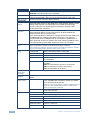
After connecting the VP-444 to the Ethernet port, configure your PC as follows:
1. Click Start > Control Panel > Network and Sharing Center.
2. Click Change Adapter Settings.
VP-444 - Controlling the VP-444
15
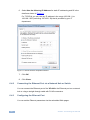
3. Highlight the network adapter you want to use to connect to the device and
click Change settings of this connection.
The Local Area Connection Properties window for the selected network
adapter appears as shown in Figure 8.
Figure 8: Local Area Connection Properties Window
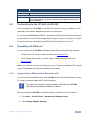
4. Highlight either Internet Protocol Version 6 (TCP/IPv6) or Internet Protocol
Version 4 (TCP/IPv4) depending on the requirements of your IT system.
5. Click Properties.
The Internet Protocol Properties window relevant to your IT system appears
as shown in Figure 9 or Figure 10.
16
VP-444 - Controlling the VP-444
Figure 9: Internet Protocol Version 4 Properties Window
Figure 10: Internet Protocol Version 6 Properties Window
VP-444 - Controlling the VP-444
17
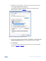
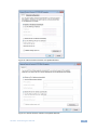
6. Select Use the following IP Address for static IP addressing and fill in the
details as shown in Figure 11.
For TCP/IPv4 you can use any IP address in the range 192.168.1.1 to
192.168.1.255 (excluding 192.168.1.39) that is provided by your IT
department.
Figure 11: Internet Protocol Properties Window
7. Click OK.
8. Click Close.
6.4.2
Connecting the Ethernet Port via a Network Hub or Switch
You can connect the Ethernet port of the VP-444 to the Ethernet port on a network
hub or using a straight-through cable with RJ-45 connectors.
6.4.3
Configuring the Ethernet Port
You can set the Ethernet parameters via the embedded Web pages.
18
VP-444 - Controlling the VP-444
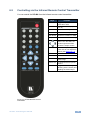
6.5
Controlling via the Infrared Remote Control Transmitter
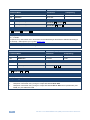
You can control the VP-444 from the infrared remote control transmitter:
Keys
POWER
Function
PC1
Toggle the power save
mode ON or OFF
Select the HDMI input (from
1 to 10)
Select the PC 1 input
PC2
Select the PC 2 input
XGA Reset
Reset the resolution to XGA
HDMI
720p Reset Reset the resolution to 720p
Four navigation keys
When not in the OSD, the
left and right arrows also
control the output volume
OK
MENU
Press to accept changes
Press also to auto adjust the
picture (see Section 6.1.1)
Enter the OSD menu
EXIT
EXIT the menu
FREEZE
Freeze/unfreeze the output
video image
Panel Lock
Lock/unlock the front panel
buttons
MUTE
Toggle between muting
(blocking out the sound) and
enabling the audio output
Figure 12: Infrared Remote Control
Transmitter
VP-444 - Controlling the VP-444
19
7 Using the Embedded Web Pages
The VP-444 can be operated remotely using the embedded Web pages. The Web
pages are accessed using a Web browser and an Ethernet connection.
Before attempting to connect:
Perform the procedures in Section 6.4.
Ensure that your browser is supported
The following operating systems and Web browsers are supported:
Windows 7:
Chrome version 35
Firefox version 30
Internet Explorer version 10
Safari (depends on the IOS version)
Mac (PC):
Chrome version 35
Firefox version 27
iOS:
Chrome version 35
Android OS:
20
Chrome version 35
VP-444 - Using the Embedded Web Pages
7.1
Browsing the VP-444 Web Pages
To browse the VP-444 Web pages:
1. Open your Internet browser.
2. Type the IP number of the device in the Address bar of your browser. For
example, the default IP number:
The Input Select Web page appears.
There are eight Web pages:
The Input Select page (see Section 7.2)
The Device Settings page (see Section 7.3)
The Output Settings page (See Section7.4)
The HDCP page (see Section 7.5)
The EDID page (see Section 7.6)
The Audio page (see Section 7.7)
The Advanced page (see Section 7.8)
The About page (see Section 7.9)
VP-444 - Using the Embedded Web Pages
21
7.2
The Input Select Page
Figure 13 shows the Input Select page that is also the first Web page. The column
on the left shows the Input Select page selected and below a list of all the other
available Web pages. The Input Select area lets you select an input to the outputs
(audio, video or audio-follow-video) the Audio out (below Output) shows the audio
input that is routed to the line and monitor outputs. The volume area lets you control
the Line and Monitor output audio level.
The model name, FW version and IP number appear on the lower left side of the
main page. The lower part of the screen lets you save the settings and upload a
saved setting.
Figure 13: The Input Select Page
On the right side you can set the volume of the microphones and the output; you can
select the mixer mode (the selection disables/enables the Mic 1/Mic 2 volume
slides). The speaker icon (
Use the freeze icon (
) lets you mute (
) or unmute the audio output level.
) to freeze a selected input. Use the edit icon (
) to edit the
input.
22
VP-444 - Using the Embedded Web Pages
To edit an input button, select that button and click the edit icon. The input edit
window appears:
Figure 14: Edit Input Buttons
The input edit window lets you set the HDCP, change the name of the input as it will
appear on the Web page and save it, and also set the audio source and its volume.
When selecting a PC input you can change the inputs’ name and set the input
volume. Upon completion, save the changes and click the exit icon (
VP-444 - Using the Embedded Web Pages
).
23
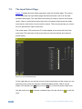
7.3
The Device Settings Page
The device Settings window (Figure 15) lets you upgrade the firmware and set the
Ethernet parameters.
Figure 15: The Device Settings Page
Any change in the device settings requires confirmation, as illustrated in the example
in Figure 16.
Figure 16: The Device Settings Page – Static IP Confirmation.
24
VP-444 - Using the Embedded Web Pages
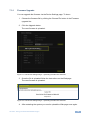
7.3.1
Firmware Upgrade
You can upgrade the firmware via the Device Settings page. To do so:
1. Choose the firmware file by clicking the Choose File button in the Firmware
upgrade line.
2. Click the Upgrade button.
The new firmware is uploaded:
Figure 17: The Device Settings Page – Uploading the New Firmware File
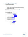
3. Once the file is uploaded follow the instructions on the Web page:
The new firmware is uploaded:
Figure 18: The Device Settings Page – Uploading the New Firmware File
4. After restarting the system you need to upload the Web page once again.
VP-444 - Using the Embedded Web Pages
25
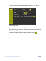
5. Make sure that the new version appears on the Web page lower left side:
Figure 19: The Device Settings Page – New Firmware Updated
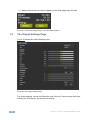
7.4
The Output Settings Page
Figure 20 shows the Output Settings page:
Figure 20: The Output Settings Page
The output settings, include the Resolution and Size, the Finetune items (which are
enabled for VGA inputs), and the picture settings.
26
VP-444 - Using the Embedded Web Pages
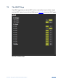
7.5
The HDCP Page
The HDCP page lets you set the HDCP on the output (follow input or follow output)
and the HDCP status for each of the HDMI inputs. Figure 21 shows the HDCP page:
Figure 21: The HDCP Page
VP-444 - Using the Embedded Web Pages
27
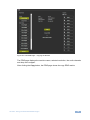
7.6
The EDID Page
The EDID page lets you copy a selected resolution (Native Timing) or the default
resolution (HDMI or VGA) to one or more selected inputs.
Figure 22: The EDID Page
Figure 23 shows how to select a resolution from the list and select one or more
inputs. To copy, click the Copy button:
28
VP-444 - Using the Embedded Web Pages
Figure 23: The EDID Page – Copying the Default
The EDID page displays the machine name, selected resolution, the audio channels
and deep color support.
After clicking the Copy button, the EDID page shows the copy EDID results:
VP-444 - Using the Embedded Web Pages
29
Figure 24: The EDID Page –The Copy EDID Results
Click Close to complete the EDID procedure.
30
VP-444 - Using the Embedded Web Pages
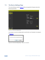
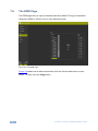
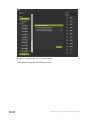
7.7
The Audio Settings Page
The audio settings page lets you define the audio parameters for the inputs, outputs
(1 and 2 together), and the microphone inputs (Mic 1 and Mic 2), as illustrated in
Figure 25.
Set Mute follow freeze and Lip sync as well as the audio source (automatic, analog
or embedded for the HDMI inputs) and volume level for each input.
Figure 25: The Audio Settings Page
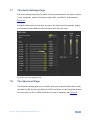
7.8
The Advanced Page
The Advanced setting page lets you set the auto sync off speed (either slow or fast)
or disable it (Off), set the auto switching to Off, Auto Scan or Last Connected and set
the input priority to PC or HDMI (once the auto scan is enabled), see Figure 26.
VP-444 - Using the Embedded Web Pages
31
Figure 26: The Advanced Page
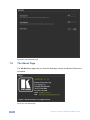
7.9
The About Page
The VP-444 About page lets you view the Web page version and Kramer Electronics
Ltd details.
Figure 27: The About Page
32
VP-444 - Using the Embedded Web Pages
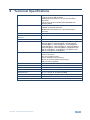
8 Technical Specifications
INPUTS:
10 HDMI connectors (HDMI, HDCP version 1.1)
2 VGA on a 15-pin HD connector
Unbalanced stereo audio on 12 3-pin terminal block
connectors
2 Mic on 6mm jack connectors (with selectable 48V
phantom power)
OUTPUTS:
2 HDMI connectors (HDMI, HDCP version 1.1)
1 S/PDIF on an RCA connector
Unbalanced stereo audio on a 5-pin terminal block
connector
BANDWIDTH:
Up to 1080p, UXGA
SWITCHING TIME BETWEEN
INPUTS:
2 to 3 seconds
VIDEO LATENCY:
Less than 2 frames
OUTPUT RESOLUTIONS:
Native, 640x480 @60Hz, 800x600 @60Hz, 1024x768 @60Hz,
1280x768 @60Hz, 1360x768 @60Hz, 1280x720 @60Hz,
1280x800 @60Hz, 1280x1024 @60Hz, 1440x900 @60Hz,
1400x1050 @60Hz, 1680x1050 @60Hz, 1600x1200 @60Hz,
1920x1080 @60Hz, 1920x1200 @60Hz, 480p @60Hz, 720p
@60Hz, 1080i @60Hz, 1080p @60Hz, 576p @50Hz, 720p
@50Hz, 1080i @50Hz, 1080p @50Hz
CONTROLS
HDMI 1 to HDMI 10 and PC 1 to PC 2 input selector buttons;
Freeze, mute buttons;
Menu and navigation buttons,
Reset to XGA/720p and lock buttons,
RS-232, IR, Ethernet (OSD and Web pages)
USB for firmware upgrading
POWER CONSUMPTION:
100-240V AC, 22VA max.
OPERATING TEMPERATURE:
0° to +40°C (32° to 104°F)
STORAGE TEMPERATURE:
-40° to +70°C (-40° to 158°F)
HUMIDITY:
10% to 90%, RHL non-condensing
DIMENSIONS:
19" x 7" x 1U (W, D, H) rack mountable
WEIGHT:
2.7kg (6lbs) approx.
INCLUDED ACCESSORIES:
Power cord, rack ears, IR remote control
Specifications are subject to change without notice at http://www.kramerelectronics.com
VP-444 - Technical Specifications
33
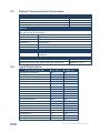
8.1
Default Communication Parameters
RS-232
Baud Rate:
9,600
Data Bits:
8
Stop Bits:
1
Parity:
None
Ethernet
To reset the IP settings to the factory reset values go to : Menu-> Factory-> RESET->Change
the option to YES and press Enter
IP Address:
192.168.1.39
Subnet mask:
255.255.255.0
Default gateway:
192.168.1.254
TCP Port #:
Not supported
Default UDP Port #:
50000
Maximum UDP Ports:
4
Full Factory Reset
OSD
Go to : Menu-> Factory-> RESET->Change the option to YES and
press Enter
RS-232/Ethernet (UDP) Command Protocol
8.2
34
Command Format:
ASCII protocol 3000
Example (Route the video HDMI3 input to the output ports):
#ROUTE 12,1,2<cr>
Input Resolutions
Resolution/Refresh Rate
640x480 (60/72/75/85Hz)
PC 1/PC 2
Yes
HDMI 1-10
Yes
800x600 (56/60/72/75/85Hz)
Yes
Yes
1024x768 (60/70/75/85Hz)
Yes
Yes
1280x720 60Hz
Yes
Yes
1280x800 60Hz
Yes
Yes
1280x1024 (60/75/85Hz)
Yes
Yes
1366x768 60Hz
Yes
Yes
1400x1050 60Hz
Yes
Yes
1440x900 60Hz
Yes
Yes
1600x1200 60Hz
Yes
Yes
1600x900 RB 60Hz
Yes
Yes
1680x1050 RB 60Hz
Yes
Yes
1920x1080 60Hz
Yes
Yes
1920x1200 RB 60Hz
Yes
480I/576I
No
Yes
Yes
480P/576P
No
Yes
720P(50/60Hz)
No
Yes
1080I(50/60Hz)
No
Yes
1080P(24/25/30Hz)
No
Yes
1080P(50/60Hz)
No
Yes
VP-444 - Technical Specifications
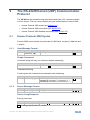
9
The RS-232/Ethernet (UDP) Communication
Protocol
The VP-444 can be operated using serial commands from a PC, remote controller,
or touch screen. The unit communicates using the default Kramer Protocol 3000.
9.1
Kramer Protocol 3000 syntax (see Section 9.1)
Kramer Protocol 3000 commands (see Section 9.2)
Kramer Protocol 3000 detailed commands (See Section 9.3)
Kramer Protocol 3000 Syntax
Protocol 3000 communicates at a data rate of 9,600 baud, no parity, 8 data bits and
1 stop bit.
9.1.1
Host Message Format
Start
Address (optional)
Body
Delimiter
#
Destination_id@
Message
CR
Simple Command
Command string with only one command without addressing:
Start
Body
Delimiter
#
Command SP Parameter_1,Parameter_2,…
CR
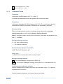
Command String
Formal syntax with commands concatenation and addressing:
9.1.2
Start
Address
Body
#
Destination_id@
Command_1 Parameter1_1,Parameter1_2,…|
CR
Command_2 Parameter2_1,Parameter2_2,…|
Command_3 Parameter3_1,Parameter3_2,…|…
Delimiter
Device Message Format
Start
Address (optional) Body
~
Sender_id@
Message
delimiter
CR LF
Device Long Response
Echoing command:
Start
Address (optional) Body
~
Sender_id@
Command SP [Param1 ,Param2 …] result
Delimiter
CR LF
CR = Carriage return (ASCII 13 = 0x0D)
VP-444 - The RS-232/Ethernet (UDP) Communication Protocol
35
LF = Line feed (ASCII 10 = 0x0A)
SP = Space (ASCII 32 = 0x20)
9.1.3
Command Terms
Command
A sequence of ASCII letters ('A'-'Z', 'a'-'z' and '-').
Command and parameters must be separated by at least one space.
Parameters
A sequence of alphameric ASCII characters ('0'-'9','A'-'Z','a'-'z' and some special
characters for specific commands). Parameters are separated by commas.
Message string
Every command entered as part of a message string begins with a message
starting character and ends with a message closing character.
Note: A string can contain more than one command. Commands are separated by a
pipe ( '|' ) character.
Message starting character
'#' – For host command/query
'~' – For machine response
Device address (Optional, for K-NET)
K-NET Device ID followed by '@'
Query sign
'?' follows some commands to define a query request.
Message closing character
CR – For host messages; carriage return (ASCII 13)
CRLF – For machine messages; carriage return (ASCII 13) + line-feed (ASCII 10)
Command chain separator character
When a message string contains more than one command, a pipe ( '|' ) character
separates each command.
Spaces between parameters or command terms are ignored.
36
VP-444 - The RS-232/Ethernet (UDP) Communication Protocol
9.1.4
Entering Commands
You can directly enter all commands using a terminal with ASCII communications
software, such as HyperTerminal, Hercules, etc. Connect the terminal to the serial or
Ethernet port on the Kramer device. To enter CR press the Enter key.
( LF is also sent but is ignored by command parser).
For commands sent from some non-Kramer controllers like Crestron, some
characters require special coding (such as, /X##). Refer to the controller manual.
9.1.5
Command Forms
Some commands have short name syntax in addition to long name syntax to allow
faster typing. The response is always in long syntax.
9.1.6
Command Chaining
Multiple commands can be chained in the same string. Each command is delimited
by a pipe character ( '|' ). When chaining commands, enter the message starting
character and the message closing character only once, at the beginning of the
string and at the end.
Commands in the string do not execute until the closing character is entered.
A separate response is sent for every command in the chain.
9.1.7
Maximum String Length
64 characters
VP-444 - The RS-232/Ethernet (UDP) Communication Protocol
37
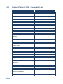
9.2
Kramer Protocol 3000 – Command List
Command
Short Form
Description
#
Protocol handshaking
#HELP
List of commands
#BUILD-DATE?
Read device build date
#FACTORY
Reset to factory default configuration
#MODEL?
Read device model
#PROT-VER?
Read device protocol version
#VERSION?
Read device firmware version
#NET-MAC?
NTMC?
Get MAC address
#NET-IP
NTIP
Set device IP address
#NET-IP?
NTIP?
Get device IP address
#NET-GATE
NTGT
Set Gateway IP
#NET-GATE?
NTGT?
Get Gateway IP
#NET-MASK
NTMSK
Set device subnet mask
#NET-MASK?
NTMSK?
Get device subnet mask
#NET-DHCP
NTDH
Set DHCP mode
#NET-DHCP?
NTDH?
Get DHCP mode
#ROUTE
#ROUTE?
#DISPLAY?
Get output HPD status
#LOCK-FP
LCK
Lock front panel
#LOCK-FP?
LCK?
GET Lock front panel
#HDCP-MOD
#HDCP-MOD?
#VID-RES
Set input/output resolution
#VID-RES?
Get input/output resolution
#VFRZ
#VFRZ?
#AUD-LVL
Set audio level
#AUD-LVL?
Get audio level
#MIX
#MIX?
#MUTE
#MUTE?
#SCLR-AS
#SCLR-AS?
#IMAGE-PROP
#IMAGE-PROP?
#SCLR-PCAUTO
#SCLR-AUDIO-DELAY
#SCLR-AUDIO-DELAY?
#MIC-GAIN
#MIC-GAIN?
38
VP-444 - The RS-232/Ethernet (UDP) Communication Protocol
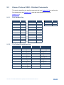
9.3
Kramer Protocol 3000 – Detailed Commands
This section describes the detailed commands list (see Section 9.3.3) as well as the
Port number key (see Section 9.3.1) and the video resolutions key (see
Section 9.3.2).
9.3.1
9.3.2
Port Number Key
Video
#
Audio input
#
Video Output
#
HDMI 1
0
HDMI 1
0
HDMI 1
0
HDMI 2
1
HDMI 2
1
HDMI 2
1
HDMI 3
2
HDMI 3
2
HDMI 4
3
HDMI 4
3
HDMI 5
4
HDMI 5
4
HDMI 6
5
HDMI 6
5
HDMI 7
6
HDMI 7
6
HDMI 8
7
HDMI 8
7
HDMI 9
8
HDMI 9
8
HDMI 10
9
HDMI 10
9
PC 1
10
PC 1
10
PC 2
11
PC 2
11
The Output Resolutions key
Resolution
Number
Resolution
0
Number
640x480 @60Hz
12
1920x1080 @60Hz
1
800x600 @60Hz
13
1920x1200 @60Hz
2
1024x768 @60Hz
14
480p @60Hz
3
1280x768 @60Hz
15
720p @60Hz
4
1360x768 @60Hz
16
1080i @60Hz
5
1280x720 @60Hz
17
1080p @60Hz
6
1280x800 @60Hz
18
576p @50Hz
7
1280x1024 @60Hz
19
720p @50Hz
8
1440x900 @60Hz
20
1080i @50Hz
9
1400x1050 @60Hz
21
1080p @50Hz
10
1680x1050 @60Hz
22
NATIVE OUT1
11
1600x1200 @60Hz
23
NATIVE OUT2
VP-444 - The RS-232/Ethernet (UDP) Communication Protocol
39
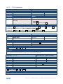
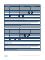
9.3.3
The Commands
Command – HELP
Command Type – System-mandatory
Command Name
Permission
Transparency
Set:
-
-
-
Get:
HELP
End User
-
Description
Syntax
Set:
-
-
Get :
Get command list or help for specific
command
2 options:
1. #HELP␍
2. #HELP␠command_name␍
Response
1. Multi-line: ~nn@Device available protocol 3000 commands:␍␊command,␠command…␍␊
To get help for command use : HELP (COMMAND_NAME) ␍␊
2. Multi-line: ~nn@HELP␠command:␍␊description␍␊USAGE:usage ␍␊
Command – BUILD-DATE
Command Name
Command Type – System-mandatory
Permission
Transparency
Set:
BUILD-DATE
End User
-
Get:
-
-
-
Description
Syntax
Set:
Read device build date
#BUILD-DATE?␍
Get :
-
-
Response
~nn@BUILD-DATE␠date␠time␍␊
Parameters
date – Format: YYYY/MM/DD where YYYY = Year, MM = Month, DD = Day
time – Format: hh:mm:ss where hh = hours, mm = minutes, ss = seconds
Command – FACTORY
Command Type – System-mandatory
Command Name
Permission
Transparency
Set:
FACTORY
End User
-
Get:
-
-
-
Description
Syntax
Set:
Reset device to factory defaults configuration
#FACTORY␍
Get :
-
-
Response
~nn@BUILD-DATE␠date␠time␍␊
Notes
This command deletes all user data from the device. The deletion can take some time.
40
VP-444 - The RS-232/Ethernet (UDP) Communication Protocol
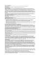
Command – MODEL?
Command Name
Command Type – System-mandatory
Permission
Transparency
Set:
-
-
-
Get:
MODEL?
End User
-
Description
Syntax
Set:
-
-
Get :
Get device model
#MODEL?␍
Response
~nn@MODEL␠model_name␍␊
Parameters
model_name – String of up to 19 printable ASCII chars
Command – PROT-VER?
Command Name
Command Type – System-mandatory
Permission
Transparency
Set:
-
-
-
Get:
PROT-VER?
End User
-
Description
Syntax
Set:
-
-
Get :
Get protocol version
#PROT-VER?␍
Response
~nn@PROT-VER␠3000:version␍␊
Parameters
Version – Format: XX.XX where X is a decimal digit
Command –VERSION?
Command Name
Command Type – System-mandatory
Permission
Transparency
Set:
-
-
-
Get:
VERSION?
End User
-
Description
Syntax
Set:
-
-
Get :
Get version number
#VERSION?␍
Response
~nn@VERSION␠firmware_version␍␊
Parameters
firmware_version – Format: XX.XX.XXXX where the digits group are: major.minor.build version
VP-444 - The RS-232/Ethernet (UDP) Communication Protocol
41
Command – NET-MAC?
Command Type – Communication
Command Name
Set:
Get:
NET-MAC?
Description
Permission
Transparency
End User
-
Syntax
Set:
Get :
Get MAC address
#NET-MAC?␍
Response
~nn@NET-MAC␠mac_address␍␊
Parameters
mac_address – Unique MAC address. Format: XX-XX-XX-XX-XX-XX where X is hex digit.
Command – NET-IP
Command Type – Communication
Command Name
Permission
Transparency
Set:
NET-IP
Administrator
-
Get:
NET-IP?
End User
-
Description
Syntax
Set:
Set device IP address
#NET-IP␠ P1 ␍
Get :
Get device IP address
#NET-IP?␍
Response
Set: ~nn@ NET-IP ␠ ip_address ␠OK␍␊
Get: ~nn@ NET-IP ␠ ip_address ␍␊
Parameters
P1 (valid IP address)= xxx.xxx.xxx.xxx
Notes
For proper settings consult your network administrator.
Command – NET-GATE
Command Name
Set:
Command Type – Communication
Permission
Transparency
NET-GATE
Administrator
-
NET-GATE?
Get:
Description
End User
Syntax
-
Set:
Set Gateway IP
#NET-GATE␠ P1 ␍
Get :
Get Gateway IP
#NET-GATE?␍
Response
Set: ~nn@ NET-GATE ␠ P1 ␠OK␍␊
Get: ~nn@ NET-GATE ␠ ip_address ␍␊
Parameters
P1 (valid IP address)=xxx.xxx.xxx.xxx
Notes
A network gateway connects the device via another network and maybe over the Internet. Be careful of
security problems. For proper settings consult your network administrator
42
VP-444 - The RS-232/Ethernet (UDP) Communication Protocol
Command – NET-MASK
Command Name
Command Type – Communication
Permission
Transparency
Set:
NET-MASK
Administrator
-
Get:
NET-MASK?
End User
-
Description
Syntax
Set:
Set device subnet mask
#NET-MASK␠ net_mask ␍
Get :
Get device subnet mask
#NET-MASK? ␍
Response
Set: ~nn@NET-MASK ␠ P1 ␠OK␍␊
Get: ~nn@NET-MASK ␠ net_mask ␍␊
Parameters
P1 (valid IP address)=xxx.xxx.xxx.xxx
Response triggers
The subnet mask limits the Ethernet connection within the local network.
For proper settings consult your network administrator.
Command – NET-DHCP
Command Name
Command Type – Communication
Permission
Transparency
Set:
NET-DHCP
Administrator
-
Get:
NET-DHCP?
End User
-
Description
Syntax
Set:
Set DHCP mode
#NET-DHCP␠ P1 ␍
Get :
Get DHCP mode
#NET-DHCP?␍
Response
Set: ~nn@ NET-DHCP ␠ P1 ␠OK␍␊
Get: ~nn@ NET-DHCP ␠ mode ␍␊
Parameters
P1 – 0=Static IP; 1=DHCP
0 – Use static IP.
1 – Use DHCP. If unavailable, use IP as above.
Notes
Connecting Ethernet to devices with DHCP may take more time in some networks.
To connect with a randomly assigned IP by DHCP, specify the device DNS name (if available) using the
command “NAME”. You can also get an assigned IP by direct connection to USB or RS-232 protocol port
if available.
For proper settings consult your network administrator.
VP-444 - The RS-232/Ethernet (UDP) Communication Protocol
43
Command – ROUTE
Command Type –
Command Name
Permission
Transparency
Set:
ROUTE
End User
-
Get:
ROUTE?
End User
-
Description
Syntax
Set:
Set layer routing
# ROUTE ␠ P1,P2,P3 ␍
Get :
Get layer routing
# ROUTE? ␠ P1,P2 ␍
Response
~ nn@ ROUTE ␠ P1,P2,P3 ␍␊
Parameters
P1 (Layer number) –12=Video+Audio
P2 – 1=Scaler
P3 (Route from, valid values are in accordance to the selected layer and Route to selected according to
P1 and P2) – video inputs = (0~11); see Section 9.3.1
Notes
This command replaces all other routing commands.
Command – DISPLAY?
Command Type - System
Command Name
Permission
Transparency
Set :
-
-
-
Get
DISPLAY?
End User
Public
Description
Syntax
Set:
-
-
Get:
Get output HPD status
#DISPLAY? ␠P1 ␍
Response
~ nn@DISPLAY ␠ P1 ␍␊
Parameters
P1 (Output number) – 0=HDMI1; 1=HDMI2
Response triggers
After execution, response is sent to the com port from which the Get was received
Response is sent after every change in output HPD status ON to OFF
Response is sent after every change in output HPD status OFF to ON and ALL parameters (new
EDID, etc.) are stable and valid
44
VP-444 - The RS-232/Ethernet (UDP) Communication Protocol
Command – LOCK-FP
Command Name
Command Type – System
Permission
Transparency
Set:
LOCK-FP
End User
-
Get:
LOCK-FP?
End User
-
Description
Syntax
Set:
Lock front panel
#LOCK-FP␠P1␍
Get :
Get front panel lock state
#LOCK-FP?␍
Response
nn@LOCK-FP␠P1␠OK␍␊
Parameters
P1– 0=No; 1=Yes
Command – HDCP-MOD
Command Name
Command Type – System
Permission
Transparency
Set:
HDCP-MOD
Administrator
Public
Get:
HDCP-MOD?
End User
Public
Description
Syntax
Set:
Set HDCP mode
#HDCP-MOD ␠ P1,P2,P3 ␍
Get :
Get HDCP mode
#HDCP-MOD? ␠ P1,P2 ␍
Response
Set / Get : ~ nn @HDCP-MOD ␠ P1,P2,P3 ␍␊
Parameters
P1 (Input/Output) – 0=Input; 1=Output
P2 (Scaler number) – Input 0-9=HDMI 1 – HDMI 10; Output 0-1=HDMI 1, HDMI 2
P3 (Status) – Input: 0=Off; 1=On; Output: 2=Follow In, 3=Follow Out
Response triggers
Response is sent to the com port from which the Set (before execution) / Get command was
received
Response is sent to all com ports after execution if HDCP-MOD was set any other external control
device (button press, device menu and similar) or genlock status changed
Notes
Set HDCP working mode on device input :
HDCP supported
– HDCP_ON [default]
HDCP not supported – HDCP OFF
HDCP support changes following detected sink – MIRROR OUTPUT
VP-444 - The RS-232/Ethernet (UDP) Communication Protocol
45
Command – VID-RES
Command Type - Video
Command Name
Permission
Transparency
Set :
VID-RES
End User
Public
Get
VID-RES?
End User
Public
Description
Syntax
Set:
Set video resolution
#VID-RES ␠P1,P2,P3,P4 ␍
Get:
Get video resolution
#VID-RES? ␠ P1,P2,P3 ␍
Response
~ nn@VID-RES ␠ P1,P2,P3,P4 ␍␊
Parameters
P1 –1=Output
P2 – 1=Scaler
P3 – 0=Off
P4 - video resolutions – 0~23, see Section 9.3.2
Response triggers
After execution, response is sent to the com port from which the Set /Get was received
After execution, response is sent to all com ports if VID-RES was set by any other external control
device (button press, device menu and similar)
Notes
1.
2.
3.
4.
“Set” command is only applicable for stage=Output
“Set” command with is_native=ON sets native resolution on selected output (resolution index sent = 0).
Device sends as answer actual VIC ID of native resolution
“Get” command with is_native=ON returns native resolution VIC, with is_native=OFF returns current
resolution
To use “custom resolutions” (entries 100-105), define them using command DEF-RES
Command – VFRZ
Command Type – Video
Command Name
Permission
Transparency
Set:
VFRZ
End User
-
Get:
VFRZ?
End User
-
Description
Syntax
Set:
Set freeze video on output
# VFRZ ␠ P1,P2 ␍
Get :
Get freeze on output status
# VFRZ? ␠ P1 ␍
Response
Set / Get : ~ nn@ VFRZ ␠ P1,P2 ␍␊
Parameters
P1 (Scaler number) – 1=Scaler
P2 (Off/On) – 0=Off; 1=On
46
VP-444 - The RS-232/Ethernet (UDP) Communication Protocol
Command – AUD-LVL
Command Type – Audio
Command Name
Permission
Transparency
Set:
AUD-LVL
End User
-
Get:
AUD-LVL?
End User
-
Description
Syntax
Set:
Set audio level in specific amplifier stage
#AUD-LVL␠ P1,P2,P3 ␍
Get :
Get audio level in specific amplifier stage
#AUD-LVL?␠ P1,P2 ␍
Response
~nn@AUD-LVL␠ P1,P2 ␍␊
Parameters
P1 (Input/Output)– 0=Input; 1=Output
P2 (Input/Output number valid according to the selected Input/Output according to P1) – audio
inputs=0~11; Audio outputs=0; (see Section 9.3.1)
P3 – 0~100
Command – MIX
Command Type – Audio
Command Name
Permission
Transparency
Set:
MIX
End User
-
Get:
MIX?
End User
-
Description
Syntax
Set:
Set audio MIX
#MIX␠ P1,P2 ␍
Get :
Get audio MIX
#MIX? ␠ P1 ␍
Response
~nn@MIX␠ channel, mix_mode ␍␊
Parameters
P1 (Output number) – 1=Scaler
P2 (Off/On)– 0=Off; 1=Mic 1; 2=Mic 2; 3=both
VP-444 - The RS-232/Ethernet (UDP) Communication Protocol
47
Command – Mute
Command Type – [Audio]
Command Name
Permission
Transparency
Set:
MUTE
End User
Public
Get:
MUTE?
End User
Public
Description
Syntax
Set:
Mute the selected output
# MUTE ␠ P1,P2 ␍
Get :
Mute the selected output
# MUTE? ␠ P1 ␍
Response
Set / Get : ~ nn @ MUTE ␠ P1,P2. ␍␊
Parameters
P1 – 0: 1=Scaler
P2 – 0=Off; 1=On
Response triggers
Response is sent to the com port from which the Set (before execution) / Get command was received
After execution, response is sent to all com ports if CMD-NAME was set any other external control
device (button press, device menu and similar) or genlock status was changed
Notes
Mutes the selected audio output
Command – Scaler As?
Command Name
Command Type – [Audio]
Permission
Transparency
Set:
SCLR-AS
End User
Public
Get:
SCLR-AS?
End User
Public
Description
Syntax
Set:
Set the auto sync off timer
# SCLR-AS ␠ P1,P2 ␍
Get :
Get the auto sync off timer
definition
# SCLR-AS? ␠ P1 ␍
Response
Set / Get : ~ nn @ SCLR-AS ␠ P1,P2…. ␍␊
Parameters
P1 (Scaler Number) –1=Scaler
P2 (Off/On) – 0=Off; 1=Fast; 2=Slow
Response triggers
Response is sent to the com port from which the Set (before execution) / Get command was received
After execution, response is sent to all com ports if CMD-NAME was set any other external control
device (button press, device menu and similar) or genlock status was changed
Notes
Sets the Auto Sync features for the selected Scaler
48
VP-444 - The RS-232/Ethernet (UDP) Communication Protocol
Command – Image Proportions
Command Name
Command Type – [Video]
Permission
Transparency
Set:
IMAGE-PROP
End User
Public
Get:
IMAGE-PROP?
End User
Public
Description
Syntax
Set:
Set the image size
# IMAGE-PROP ␠ P1 ␍
Get :
Get the image size
# IMAGE-PROP? ␠ P1,…,P6 ␍
Response
Set / Get : ~ nn @ IMAGE-PROP ␠ P1,P2…. ␍␊
Parameters
P1 (Scaler number) – 1=Scaler
P2 (Status) – 0=Over Scan; 1=Full; 2=Best Fit; 3=PanScan; 3=Letter Box; 5=Under 2; 6=Under 1
Response triggers
Response is sent to the com port from which the Set (before execution) / Get command was received
After execution, response is sent to all com ports if CMD-NAME was set any other external control
device (button press, device menu and similar) or genlock status was changed
Notes
Sets the image properties of the selected scaler
Command – PC Auto Sync
Command Name
Command Type – [Video]
Permission
Transparency
End User
Public
Get:
End User
Public
Description
Syntax
Set:
Set:
SCLR-PCAUTO
Set
# SCLR-PCAUTO ␠ P1,P2 ␍
Get :
Response
Set / Get : ~ nn @ SCLR-PCAUTO ␠ P1,P2…. ␍␊
Parameters
P1 (Scaler number) –1=Scaler
P2 (Off/On) –1=Yes
Response triggers
Response is sent to the com port from which the Set (before execution) / Get command was received
After execution, response is sent to all com ports if CMD-NAME was set any other external control
device (button press, device menu and similar) or genlock status was changed
Notes
Sets the PC Auto sync of the selected scaler
VP-444 - The RS-232/Ethernet (UDP) Communication Protocol
49
Command – Scaler Audio Delay
Command Type – [Audio]
Command Name
Permission
Transparency
Set:
SCLR-AUDIO-DELAY
End User
Public
Get:
SCLR-AUDIO-DELAY?
End User
Public
Description
Syntax
Set:
Set the scaler audio delay
# SCLR-AUDIO-DELAY ␠ P1,P2 ␍
Get :
Get the scaler audio delay
# SCLR-AUDIO-DELAY? ␠ P1 ␍
Response
Set / Get : ~ nn @ SCLR-AUDIO-DELAY ␠ P1,P2 ␍␊
Parameters
P1 (Audio output number) –1=Scaler
P2 (Level selecetion) – 0=Off; 1=40ms; 2=110ms; 3=150ms
Response triggers
Response is sent to the com port from which the Set (before execution) / Get command was received
After execution, response is sent to all com ports if CMD-NAME was set any other external control
device (button press, device menu and similar) or genlock status was changed
Notes
Sets the audio delay for the selected audio output
Command – Microphone Gain
Command Type – [Audio]
Command Name
Permission
Transparency
Set:
MIC-GAIN
End User
Public
Get:
MIC-GAIN?
End User
Public
Description
Syntax
Set:
Set the microphone gain
# MIC-GAIN ␠ P1,P2,P3 ␍
Get :
Get the microphone gain
# MIC-GAIN? ␠ P1 ␍
Response
Set / Get : ~ nn @ MIC-GAIN ␠ P1,P2, ␍␊
Parameters
P1 (always 0) – 0
P2 - 0=Mic 1; 1=Mic 2
P3 (level) – 0 to 100
Response Triggers
Response is sent to the com port from which the Set (before execution) / Get command was received
After execution, response is sent to all com ports if CMD-NAME was set any other external control
device (button press, device menu and similar) or genlock status was changed
Notes
Sets the Microphone input audio gain
50
VP-444 - The RS-232/Ethernet (UDP) Communication Protocol
For the latest information on our products and a list of Kramer distributors, visit
our Web site where updates to this user manual may be found.
We welcome your questions, comments, and feedback.
Web site: www.kramerelectronics.com
E-mail: [email protected]
!
P/N:
SAFETY WARNING
Disconnect the unit from the power
supply before opening and servicing
2900- 300305
Rev: 3