1
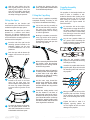
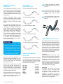
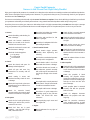
PARAJET ZENITH PARAMOTOR
THE SKY’S YOUR PLAYGROUND
Welcome to your new Parajet Zenith Paramotor.
You’re about to embark on a dynamic
and responsive flying experience.
Let’s get started.
Congratulations!
Safety Guidelines
Your Parajet Zenith paramotor is the leading paramotor of choice
for beginner and experienced recreational pilots worldwide.
I guarantee you have made an excellent choice and that every
effort has been made to ensure your purchase is a top-quality,
thoroughly-tested design, ready to provide many years of
enjoyable flights and just as many safe landings.
Flying your Parajet Zenith paramotor is renowned for its safety due
to the inherent stability, ease of control and resistance to stalls.
It is essential that you read and understand all of the following
safety guidelines - in addition to the warnings and instructions
contained within this manual - prior to using your Parajet Zenith
paramotor. Contact an Authorised Parajet Dealer or Parajet direct
if any of these instructions are unclear.
The Parajet Zenith has been designed and manufactured by our
vastly experienced team of pilots, designers and engineers at our
UK factory where meticulous assembly procedures and handbuilt production, ensures the highest levels of quality and safety
controls. Every engine is checked, fine tuned and run-up before
shipment.
The Parajet Zenith paramotor is to be used only after having
received adequate and proper training from a qualified
paramotor instructor.
The total weight limit of the Parajet Zenith paramotor is
352lbs (160kg).
As a fellow pilot, I have a true passion for flying and for the sport
of paramotoring and I hope that you will have as much fun and
exhilaration as I do.
The Parajet Zenith paramotor should only be used with
paragliders designed for paramotoring and correctly sized
for the combined weight of the paramotor, pilot and cargo.
Happy flying!!
Pilots are seriously advised to fly the Parajet Zenith
paramotor with an adequate reserve parachute fitted. While
wing failures are very rare, a reserve parachute can save
your life.
IMPORTANT:
Pilots should always wear a helmet designed for powered
paragliding/paramotoring. It is also advised that pilots wear
adequate footwear with good ankle support and gloves.
Because some of the features and
guidelines for using your Parajet Zenith paramotor merit
close attention, it is very important that you familiarise
yourself with the paramotor by reading this entire manual
before use. If you have any questions, please contact an
Authorised Parajet Dealer or check the Parajet website at
www.parajet.com.
A pre and post flight check of your Parajet Zenith paramotor
is essential. Inspect and maintain your equipment as
outlined in the “Harness to Hub Safety Checklist” of this
manual.
Introduction
Before starting the engine, check immediate area near the
propeller for lines, ropes, clothing and anything that could
be caught in the moving propeller or drive pulleys.
Your Parajet Zenith paramotor is shipped 95% factoryassembled. You only need to put together the protective outer
ring, connect the quick-release fuel tank and attach the harness.
Once you have completed the assembly and you’ve read the
safety guidelines you’re ready to get flying. Assembly should take
10-15 minutes and requires no tools. Before any flight, be sure
you carry out a comprehensive ‘harness to hub‘ safety check and
have a thorough understanding of the paramotor’s features and
operation.
Always warn any persons nearby before starting the engine;
Make it a habit to shout ‘Clear Prop’ in a loud and clear
voice.
The turning propeller can cause considerable damage and
injury. Be aware and stay clear of all moving parts such as
propellers, pulleys and belt. After prolonged engine use stay
clear of hot engine parts and exhaust muffler.
NOTE: Any reference to left or right and front or back is made in
the direction of travel, as if you were sitting in the harness facing
forward with the paramotor on your back.
Before launching your Parajet Zenith paramotor check
harness and helmet buckles are fastened and secure. Also
ensure that the paraglider is attached correctly and that the
karabiners are fastened securely.
WARNING:
Do not fly low level over water, woodland, or potentially
hazardous landing areas. Do not fly into controlled airspace
or over built up areas, it essential always to consider a safe
landing area should you experience difficulty.
YOU MUST READ THIS MANUAL AND
AGREE TO THE CONDITIONS OF USE BEFORE USE. You
will use the Parajet Zenith paramotor at your own risk.
Due to the inherent risk in flying any motorised paraglider,
no guarantee of any kind can be made against accidents,
bodily injury and/or death. Be sure to make all required
checks on the power unit and paraglider before every
flight. Never try to fly if you find any part of your paramotor
damaged or suspect a malfunction. THIS MANUAL IS NOT
A SUBSTITUTE FOR FLIGHT TRAINING. PROPER TRAINING
BY A QUALIFIED INSTRUCTOR IS ESSENTIAL.
Always be aware of the weather. Conditions can change
rapidly. Never fly if large cumulus clouds are forming and
never fly in the rain.
To maximise your fun and enjoyment, always fly the Parajet
Zenith paramotor within your known limits and capabilities.
1
PARAJET ZENITH PARAMOTOR
OWNERS INSTRUCTION & SAFETY MANUAL :: V2.2 :: NOV 2014
Fitting the Stand
Fitting the Harness & ‘Swan
Neck’ Pivot Arms
The Parajet Zenith paramotor stand
is supplied in three pieces, two stand
uprights and one crossbar.
1
The Parajet Zenith paramotor harness and
‘swan-neck’ pivot arms are supplied ready
assembled.
Insert the end of the crossbar into
the crossbar mount located near the
base of each leg. Push the crossbar
until the button clip engages and
secures the bar in position.
1
On the rear of the backplate, locate
the harness attachment slots. Each
slot is number both on the front and
back of the backplate.
2
Starting with slot 1, thread the
attachment strap through and loop
back through slot 2. Now thread the
strap through slot 3 and loop back
through slot 4.
3
Finally thread the strap through slot
5 where any excess strap material
should be safely pushed inside the
backplate.
4
Make sure the harness is located
tight against the backplate and that
the attachment straps are pulled as
tight as possible.
Fitting the Fuel Tank
2
1
Align the quick-release fuel tank to
the bottom of the backplate with the
‘Parajet’ logo facing towards the
rear of the paramotor.
2
Slide the fuel tank upwards so that
the carry handle fits neatly between
the blackplate, making sure the
retaining pin mounting holes align
correctly at the bottom of the
chassis.
Align each leg of the stand assembly
with the mounting apertures found
on the each side of the backplate,
making sure the crossbar is located
towards the front of the chassis.
Push each leg until the button clip
engages and secures the stand in
position.
3
Remove the retaining bolts from the
outer ring clamps located at the end
of each leg. Keep these bolts in a
safe place.
4
Align the detached outer ring
section with one of the outer ring
clamps, so that the netting channel
is orientated towards the front of
the paramotor.
5
Thread the ring section through
both outer ring clamps until the ring
section is centrally located.
3
Push the quick-release retaining pin
into the mounting hole and rotate
the pin 90 degrees in a clockwise
direction to lock in position and
secure the tank to the chassis.
5
Next, locate the pivot arm hinge
blocks on the left and right sides
of the backplate. Push each safety
locking pin upwards and fully extend
the pivot arm retaining pins.
4
Connect the fuel line to the tank
using the push-fit connector located
on the top right of the fuel tank. To
release the fuel line, squeeze the
metal tabs and pull apart.
6
Insert each ‘swan-neck’ pivot arm
into the hinge blocks making sure
the mounting holes align correctly.
Push the pivot arm retaining pins
back into the hinge blocks.
2
PARAJET ZENITH PARAMOTOR
OWNERS INSTRUCTION & SAFETY MANUAL :: V2.2 :: NOV 2014
7
Slide the safety locking pins into
their original position to secure the
retaining pins in place. The pivot
arms are now locked in placed and
cannot be released without sliding
the safety locking pins upwards.
Fitting the Spars
The procedure for the insertion and
removal of the spars is identical for all six
needed to complete the cage system.
Please Note: Two spars have a buckle
mounted on a stainless steel dowel.
These are for harness attachment and
supporting the fuel tank - These spars are
to be located in the mounting apertures at
the bottom of the backplate.
1
Insert the end of the spar into the
mounting aperture located on the
backplate, making sure the spar
is curved towards the rear of the
paramotor.
2
Push the spar until the button clip
engages and secures the spar in
position.
5
Fitting the Cage Ring
The outer cage is supplied as a partially
completed assembly consisting of five
ring sections threaded with the netting.
1
Lay out the outer ring assembly to
the left hand side of the paramotor.
The outer ring sections will be
threaded together with the netting
in order of application.
2
Working in a clockwise, connect the
outer ring sections to the spars by
pushing the nylon aero connectors
located at the end of each spar into
the outer ring sections.
3
3
4
Push the nylon aero connectors
located at the ends of the lower
spars into the base outer ring
section. Replace retaining bolts into
the outer ring clamps and tighten
to secure lower ring section to the
stand.
To release the harness from the
spars, squeeze both red tabs located
on the buckle and pull apart.
Before connecting the fifth and final
ring section, insert the tensioner
slide-lugs into the netting channel
of the base ring section.
4
Ensure that the netting is located in
a central position and equal length
on both sides of the cage. Make
adjustments by sliding the netting
around the netting channel.
5
On the outer cage, thread the
tension strap through the ratchet
buckle. Pump the ratchet handle
until the desired outer ring tension
is achieved.
6
Thread the netting tension cord
into the channel in the base of
the fuel tank, ensuring the cord is
located on the front (pilot side) of the
spar. Thread the tension cord strap
through the ratchet buckle. Pump
the ratchet handle until the desired
outer ring tension is achieved.
To secure the harness to the spars,
use the quick-release buckle on
each side of the harness to connect
to the buckle on the lower spars.
3
Propeller Assembly
& Attachment
The propeller for the Parajet Zenith can
rotate in either a clockwise or anticlockwise direction when looking at the
paramotor from the rear. This is crucial
when fitting the propeller to the hub,
please check your engine manual for
more information.
1
To mount the hub to the engine,
align the hub to engage the teeth of
the spline, making sure the central
recess on the hub is oriented away
from the engine. Insert the central
hub bolt and tighten to 40nm.
2
Lay the two propeller blades on
the ground while orientating the
blades so that the ‘Parajet’ propeller
stickers are facing upwards.
3
Slide the two propeller blades
together ensuring that the mounting
holes align correctly.
4
Insert the six propeller bolts into the
propeller plate. Align the bolts with
the mounting holes and insert into
the propeller.
5
Wrap your hand over the top of the
propeller plate and bolts. Picking
up the propeller, align the propeller
bolts to the mounting holes on the
hub.
6
Tighten the bolts to 10nm in a
diagonal, opposing pattern. Do
not over tighten as this can cause
damage to the propeller.
PARAJET ZENITH PARAMOTOR
OWNERS INSTRUCTION & SAFETY MANUAL :: V2.2 :: NOV 2014
Weight-shift harness
adjustment
Pilot weight
adjustment guide
The Parajet paramotor harness is a mid/
low hang point system. Parajet has always
been a strong advocate of the mid/low
hang point attachment and it has been a
permanent feature throughout their range
of paramotors.
For pilots weighing less than 75kg.
Parajet’s innovative design offers
improved wing feedback and an optimised
thrust line while removing the normal
swing or rocking motion found under
throttle.
For pilots weighing 75-85kg.
This combination of mid/low hang point
attachment and articulated pivot arms
culminates in the ability for the pilot to
control direction without the ongoing
control input. Known as weight-shift,
this dynamic feature works through the
pilot’s weight effecting the orientation
of the pivot arms, which in turn provides
input into the wing. Weight-shift enables
pilots to emanate the agile characteristics
of free-flight with manoeuvrability so
precise, that the paramotor feels like an
extension of their body.
IMPORTANT:
To achieve the
best flying characteristics of the
harness it is important that you
spend time to fully understand the
adjustment system and set it up for
your optimum weight setting. Failure
to do this accurately will result in
poor handling, an uncomfortable
flying experience and could lead to
a potentially hazardous accident.
The harness should be adjusted to suit
both your physique and flying style. It is
important to adjust it correctly to ensure
you can easily slide into the sitting
position after take-off.
While we have endeavoured to provide
concise and accurate instructions for
harness adjustment, we recommend that
these be tested before your first flight by
hanging in a simulator with the aid of a
qualified paramotor instructor.
Due to the dynamic nature of the harness,
additional fine-tuning of adjustments
maybe required during your first few
flights to ensure optimum comfort.
1
To adjust the offset pins, unfasten
the 6mm attachment bolts from the
pivot arm.
2
Locate the offset pin to the desired
position on the pivot arm based
on your weight range (see guide
above).
3
Secure the offset pin in place using
the attachment bolts, tightened to
20 Nm.
For pilots weighing 85-100kg.
For pilots weighing 100-120kg.
Adjusting the harness straps
The Parajet paramotor harness has been
designed to offer maximum adjustment to
give you many hours of comfort, freeing
you up to enjoying your flying. The harness
should be adjusted to suit your physique
and flying style. It is important to adjust
the harness correctly to ensure you can
easily slide into the sitting position after
take-off. Before making any adjustments,
loosen all straps and webbing.
For pilots weighing more than 120kg.
Adjusting the harness
offset pins
The Parajet paramotor harness is shipped
with the offset pins already attached to
the pivot arms. Always ensure the offset
pins are installed on the correct side of
the pivot arm for your engine.
Left-hand
Right-hand
Left-Hand
Left-Hand
Left-Hand
Right-hand
Right-hand
Right-hand
Thor 130
Thor 190
Thor 200
Thor 250
Top80
Minari
Moster
Bailey V5
4
Leg Straps
Correct adjustment of the leg straps
enables you to easily deploy the seatboard
and reach the sitting position after takeoff without using your hands. In the
standing position, use the quick-release
buckle to secure each strap around the
thigh. Symmetrically adjust the leg straps
using the handle loops so that they fit
comfortably without being tight.
Waist Strap
The waist strap adjusts to give you
a variable level of movement within
the harness. The waist strap may also
be adjusted in flight according to the
conditions; for example, it may be
tightened in turbulent air and flown at a
looser setting in less turbulent conditions
to allow for easier weight shift.
PARAJET ZENITH PARAMOTOR
OWNERS INSTRUCTION & SAFETY MANUAL :: V2.2 :: NOV 2014
Chest Strap
The chest strap can be moved up and down
the shoulder straps. Adjust the position of
strap to fit across the upper part of your
chest. Then fasten the quick-release
buckle and adjust the length to take some
lateral tension off the shoulders.
Shoulder Straps
The optimum setting for the shoulder
straps depends on your height. Stand
upright with the chest and leg straps
fastened and symmetrically adjust the
shoulder straps using the handle loops
until the straps are a snug fit, but not over
tight. To confirm correct adjustment squat
down into the harness, the seatboard
should deploy automatically.
Lateral Comfort Straps
The lateral straps adjust to stabilize the
weight of the paramotor when not in the
seating position. Symmetrically adjust
the comfort straps using the handle loops
until the paramotor rests comfortably on
your torso.
Seatboard Straps
The seatboard straps change the depth
of the seat. Adjust to find a comfortable
position. Lengthening the straps helps
you to slide easily into the harness at take
off, while shortening the straps helps you
to be in the standing position for landing.
Fueling your paramotor
The Parajet Zenith paramotor uses a
2-stroke petrol engine that requires a
mixture of oil and fuel in the ratio of 1:50.
Therefore you need to add 20cc (or ml) of
synthetic oil for each litre of fuel.
Your engine has been designed to use
regular unleaded gasoline with a pump
octane number [(R+M)/2] of 95 or higher.
We recommend the use of Castrol Power
1 Racing 2T and Mobil 1 Racing 2T or
equivalent fully synthetic 2-stroke oil.
Please check your engine manufacturer’s
user manual for detailed fuel requirements.
NOTE: The nature of the carbon deposits
on the cylinder head, spark plug and
exhaust port give important information
about the fuel mixture burning in your
engine. Remember that mixes that contain
too much or too little oil do not extend the
engine’s life.
WARNING:
Gasoline
and
gasoline vapors are extremely
flammable. To avoid fires and
explosions and to reduce the risk of
injury, never re-fuel while smoking,
or while in the vicinity of sparks,
open flames, or other sources
of ignition. Carry out re-fuelling
operations in a well ventilate place
and with the engine switched off.
Always make sure that the fuel cap
is properly fitted after re-fuelling.
1
Conduct a thorough pre-flight
inspection as outlined in the
“Harness to Hub Safety Checklist”
of this manual. Check you have
an adequate level of fuel for the
duration your flight.
2
Before starting the engine, check
immediate area near the propeller
for lines, ropes, clothing and
anything that could be caught in the
moving propeller or drive pulleys.
3
Always warn any persons nearby
before starting the engine; Make it a
habit to shout ‘Clear Prop’ in a loud
and clear voice.
Carburettor Settings
The engine utilises a carburettor which
atomises the fuel, controlling its mixture
with air, and regulating the intake of the
air-petrol mixture into the engine.
The carburettor can be effected by climatic
conditions causing it to behave differently
and therefore will require adjustment in
order to ensure a smooth running engine.
The engine is shipped with the carburettor
set to a default factory setting suitable
for general use and will ensure plenty of
fuel is entering the engine. If the engine is
performing well under this factory setting,
then it is possible you will not need to
make any adjustments.
NOTE: It is important to thoroughly read
and understand the carburettor settings
and adjustment, as outlined in the engine
manufacturer’s user manual.
Starting your paramotor
Priming the Engine
1
2
3
To start, the engine requires the
fuel system to be primed. Squeeze
the priming bulb to pull the fuel into
the system. To make this operation
easier push softly the diaphragm
nipple located on the carb.
Continually squeeze the priming
bulb, stopping immediately you
see the fuel reach the carburettor
inlet. Failure to stop will result in the
engine becoming flooded with fuel.
Squeeze the priming bulb one final
time to let a small amount of fuel
into the carburettor.
Pull Start Engines
Failure to understand these procedures
may lead to incorrect or dangerous
settings and can cause irreparable engine
damage and invalidates the engine and
paramotor warranty.
Prior to starting the engine
We recommend that you do not run your
Parajet Zenith paramotor while placed on
the ground without adequate support. Be
sure to choose a flat area of ground which
is well ventilated. Do not start the engine
indoors or in other poorly ventilated
areas. Experience has proven that it is
much safer to carry out all pre-flight
power checks with the paramotor firmly
strapped on your back.
5
1
Attach the hand control to your
right hand using the velcro strap.
Slide the hand control underneath
the chassis handle located at the
top of the backplate, wrapping your
fingers over the top.
2
Brace the bottom of the paramotor
using your left foot, applying
pressure to the chassis.
3
Making sure your thumb is lightly
covering the kill switch, take the
pull-start handle in your left hand.
Bracing your right arm, pull the
starter cord upward quickly and
firmly. You may have to do this
several times before the engine
starts.
PARAJET ZENITH PARAMOTOR
OWNERS INSTRUCTION & SAFETY MANUAL :: V2.2 :: NOV 2014
Electric Start Engines
1
Keeping your body tight, straighten
yourself upright while driving
through your heels, keep the balls of
your feet on the ground as well, until
you are in the standing position.
Press and hold the start button on
the hand control until the engine
starts. Do not hold for longer than
10 seconds. Once the engine has
started release the start button
immediately.
Allow the engine run on idle for
60 seconds without applying any
throttle. Shut off the engine by
holding down the kill switch on the
hand control until the engine has
completely stopped.
Getting into the harness
1
2
Before getting into the harness,
attach hand control to the pivot
arm, loosen the shoulder straps and
ensure leg, waist and chest buckles
are unfastened. Ensure straps are
untangled and positioned to aid
you in locating them once in the
harness.
Drop onto your knees with the
harness behind you. Shuffle
backwards until the seatboard is
pressed against your upper legs.
3
Fasten both leg straps using the
quick-release buckles. Slip both
arms into the shoulder straps before
fasthening the waist and chest
straps.
4
Lean forward onto both hands.
Bring your left knee to your chest so
that your foot is flat on the ground.
Repeat the same with the right foot,
using your hands to steady yourself.
Place a foot out in front of you to
brace yourself against while gently
accelerating and with varying
power output intensity. Run the
engine in this way for five minutes to
ensure the engine reaches optimum
operating temperature.
5
The turning propeller can cause
considerable damage and injury. Be
aware and keep persons at a safe
distance. After prolonged engine
use stay clear of hot engine parts
and exhaust muffler.
Tighten the shoulder straps using
the handle loops until the straps
are a snug fit, but not over tight.
To confirm correct adjustment
squat down into the harness
- the seatboard should deploy
automatically.
Kill the Engine
1
4
Warming up your paramotor
Before starting the engine it is important
to carry out the Six Point Check ensuring
your harness and helmet buckles are
fastened and secure. Also ensure that the
paraglider is clipped-in correctly and that
the karabiners are fastened securely.
Run up your Parajet Zenith paramotor as
instructed below to ensure that the engine
and transmission are warmed up correctly
and to ensure continuous reliability in the
future.
1
Unfasten the hand control from the
pivot arm and attach it to your right
hand using the velcro strap.
2
Check your immediate area in a
360 degree arc to make sure any
persons are at a safe distance.
Always warn any persons nearby
before starting the engine; Make it a
habit to shout ‘Clear Prop’ in a loud
and clear voice.
3
Making sure your thumb is lightly
covering the kill switch, start the
engine using the pull-start handle
or by pressing the start button if
your engine is fitted with an electric
starter. Allow the engine run on idle
for a couple of minutes without
applying any throttle.
6
NOTE: During your first flights or for
the first 20 litres of fuel we suggest not
keeping the engine at the maximum
RPM for extended periods of time. We
suggest varying the engine’s RPM and
utilising the entire rev range. This running
in procedure should be carried out every
time you change one of the following
parts: piston, rings, cylinder, crankshaft or
main bearings.
PARAJET ZENITH PARAMOTOR
OWNERS INSTRUCTION & SAFETY MANUAL :: V2.2 :: NOV 2014
Parajet Zenith Paramotor
‘Harness to Hub’ Pre and Post-Flight Safety Checklist
Flying your Parajet Zenith paramotor is renowned for its safety due to the meticulous assembly procedures and small batch production,
which ensures the highest level of quality control. However, it is good practice that you carry out a thorough check of your equipment
both before and after EVERY flight.
The Harness to Hub Safety Check should only take around 15 minutes to complete. These checks will help you familiarise yourself with
your paramotor and enable you to identify wear and tear or any potential mechanical problems while safely on the ground.
Should any issues occur during your Harness to Hub Safety Check it is highly recommend that you DO NOT start the engine or attempt
to fly your paramotor until you have had the chance to make adequate repairs or fit replacement parts. You do so at your own risk.
1. Harness
Check all webbing and stitching for
wear or damage.
Check the harness attachment
points are secured to the chassis
and free from excessive wear.
Check the seat board is secure and
free from wear or damage.
Check the 5 main hangpoints:
2 x leg straps
1 x waist strap
2 x karabiners.
Check the fuel pickup pipe reaches
the bottom of the fuel tank.
Check air filter is securely mounted
to the carburettor and chassis.
Check the tank and lines for fuel
leaks or spillages.
Check the cylinder head for signs of
oil leaks and ensure crankcase bolts
are tight.
Ensure there is adequate fuel for the
planned flight duration.
Check engine mounts are secure
and free from wear or damage.
4. Hand Control & Throttle
Check throttle trigger operates
smoothly when depressing and
releasing.
Check all nuts, bolts and springs on
the exhaust system are secure and
that the exhaust is free from wear or
damage.
Check cruise control wheel operates
correctly and is not tightened.
Check the exhaust silencer is clean
and not coked.
2. Chassis
Check the chassis and spars for
damage and misalignment.
Check all spar and outer ring
connections fit correctly and are
secure.
Check netting is secure and
tensioned correctly. Check for wear
or damage.
Check the hinge blocks, pivot arms
and offsets are secure and free from
wear or damage.
Check throttle cable is free from
twists and clear of wear or damage.
Check the throttle arm, located on
the carburettor, operates smoothly
with a full range of movement from
the idle pin through to the throttle
stop.
5. Pull Starter
Check pull cord is correctly mounted
to the chassis. The pull-start handle
should face towards the harness.
Check pull cord for wear or damage.
Check for excessive lateral
movement of the pivot arms. A small
amount of movement is acceptable.
3. Fuel System
Check the fuel tank quick-release
retaining pin and fuel line push-fit
connectors are secure.
Check there is good compression
by pulling gently on the pull-start
handle. You should feel some
resistance.
Check spark plug cap is secure and
has a tight seal.
7. Hub & Propeller
Check the hub is fully engaged with
the spline and the central hub bolt is
secure. Ensure hub is free from wear
or damage
Check the propeller is fitted
correctly. The propeller stickers
should face toward the rear of the
paramotor. Ensure the leading edge
and tips are clean and free from
wear or damage.
Check propeller plate is mounted
correctly and that the properller
bolts are secure.
Check for adequate clearnace
between the propeller and outer
cage ring.
Check for excessive movement
in the propeller bearings. A small
amount of movement is acceptable.
6. Engine
Check fuel lines are in good
condition - over time fuel lines go
hard, crack and let air in.
Check carburettor for any signs of
fuel leaks.
7
PARAJET ZENITH PARAMOTOR
OWNERS INSTRUCTION & SAFETY MANUAL :: V2.2 :: NOV 2014
Parajet Zenith Paramotor - Chassis Parts List
All of your Parajet Zenith paramotor parts have been designed,
tested and manufactured according to Parajet’s uncompromising
standards to ensure the superior quality and durability of every
component. You can have complete confidence in each part and
component with its fit, quality, durability and function.
To get the best out of your Parajet Zenith paramotor and to keep
it as safe and trouble-free as possible, we recommend that you
have it maintained and serviced at regular intervals by our trained
engineers. When ordering any parts, please make sure you quote
the part number.
ZENITH BACKPLATE ASSEMBLY
ZC008
1
ZA001
Complete Backplate Assembly
2
ZA003
Complete Hinge Block Assembly
1
ZA004
Complete Pull Start Bracket Assembly
1
ZC001
Backplate - Front
1
ZC002
Backplate - Rear
12
ZC003
Backplate Nylon Spacer
2
ZC004
Hinge Block
2
ZC005
Hinge Block Pin
2
ZC006
Hinge Block Locking Pin
1
ZC007
Pull Start Bracket
1
ZC008
Pull Start Pulley Wheel
1
ZC009
Pull Start Pulley Wheel Bush/Dowel
68
ZF-SSM410LOWCAP
Backplate Assembly Screw
ZC009
ZC007
ZF-SSM410LOWCAP
ZC006
ZC003
ZC003
ZC005
ZF-SSM410LOWCAP
ZF-SSM410LOWCAP
ZF-SSM410LOWCAP
ZC004
ZC003
ZC001
ZC002
ZC003
ZC003
ZF-SSM410LOWCAP
ZC003
ZF-SSM410LOWCAP
ZF-SSM410LOWCAP
ZC006
ZC005
ZC004
PARAJET ZENITH PARAMOTOR
OWNERS INSTRUCTION & SAFETY MANUAL :: V2.2 :: NOV 2014
Parajet Zenith Paramotor - Chassis Parts List
ZENITH STAND ASSEMBLY
ZC036
VF-M525
ZC035
1
ZA005
Complete Stand Assembly
2
ZC035
Stand Crossbar Boss
2
ZC036
Stand Leg Uprights
2
ZC037
Stand Feet
1
ZC038
Stand Crossbar Tube
4
CE012
Button Clip
2
VF-M525
M5 x 25mm Caphead Socket Screw
2
ZF-M5X1.5HELI
M5 x 1.5D 8mm Helicoil
12
ZF-SSM408CS
M4 x 8mm Countersunk Screw
1
ZA008
Complete Fuel Tank Assembly
1
ZA009
Complete Tank Handle Assembly
1
ZC029
Fuel Tank
1
VAF017
Fuel Cap
1
VAF026
Fuel Tank Filter
2
ZC24
Fuel Tank Support Dowel
2
ZC025
Fuel Tank Handle
2
ZC026
Fuel Tank Handle Mount
2
VF-M616BT
M6 x 16mm Handle Mount Screw
1
ZC027
Fuel Tank Handle Spacer
10
ZF-SSM408LOWCAP
Fuel Tank Assembly Screw
1
ZC028B
Fuel Tank Bung
2
ZC028C
Fuel Pipe Quick Release Nipple
1
ZC031
Fuel Pipe Quick Release - Male
1
ZC032
Fuel Pipe Quick Release - Female
1
VE045
Tygon Fuel Line Tubing
8
ZA002
Complete Cage Spar Assembly
8
ZC010
Cage Spar
16
ZC011
Spar Outer Ring Nylon Connector
8
CE012
Spar Button Clip
32
ZF-SSM412CAP
Spar Outer Ring Connector Screw
ZC037
VF-M525
ZF-SSM408CS
ZC038
ZC037
ZF-SSM408CS
ZC035
ZENITH FUEL TANK ASSEMBLY
ZC025
ZC027
ZF-SSM408LOWCAP
ZF-SSM408LOWCAP
ZC026
VAF017
ZA006
ZC026
ZC024
ZC028C / ZC031 / ZC032
ZC029
ZC024
ZENITH CAGE SPAR ASSEMBLY
ZF-SSM412CAP
ZC011
CE012
ZC010
ZF-SSM412CAP
PARAJET ZENITH PARAMOTOR
OWNERS INSTRUCTION & SAFETY MANUAL :: V2.2 :: NOV 2014
Parajet Zenith Paramotor - Chassis Parts List
ZENITH CAGE RING ASSEMBLY
ZC012
1
ZA010
Complete Cage Ring Assembly
8
ZC012
Outer Ring Section
2
ZC013
Netting Slide Lugs
1
ZC044
Outer Cord Ratchet Buckle
1
ZC045
Inner Cord Ratchet Buckle
1
ZC046
1mm Netting
1
ZC050
2mm Dyneema Cord
1
ZC051
4mm Dyneema Cord
1
ZC052
25mm Webbing Strap
1
ZC053
40mm Webbing Strap
2
ZC070
100mm Plastic Tubing
2
ZA007
Complete Pivot Arm Assembly
2
ZC016
Swan Neck Pivot Arm
2
ZC018
Offset Block
2
ZC019
Offset Pin
4
VAF010
Pivot Arm Bush
4
VF-M830BT
M8 x 30mm Button Socket Screw
4
VF-M8WSPRING
M8 Spring Washer BZP
4
VF-M8W
M8 Plain Washer BZP
1
HC020MKII
Complete Hand Control Assembly
1
HC001
Hand Control Body
1
HC002
Throttle Trigger
2
HC003
Hand Control Cover
1
HC004
Cruise Control Wheel
1
HC005
Starter Button - Green
1
HC006
Stop Button - Red
1
HC007
Hand Control O-Ring
1
HC008
Hand Control Strap
1
HC009A
Throttle Cable - Electronic
1
HC010
Throttle Cable Sheath
1
HC011
Hand Control Wiring
1
HC022
Throttle Spring
1
VF-M416CSK
M4 x 16mm Countersunk Screw
1
VF-M45GR
M4 x 5mm Grub Screw BZP
1
VF-M6W
M6 Plain Washer BZP
ZENITH PIVOT ARM ASSEMBLY
VAF010
VF-M830BT
VF-M8WSPRING
ZC016
VF-M8WSPRING
ZC019
ZC018
PARAJET HAND CONTROL ASSEMBLY
HC005
HC003
HC006
HC003
HC007
VF-M6W
HC008
VF-M45GR
VF-M416CSK
HC004
HC002
HC001
HC010
PARAJET ZENITH PARAMOTOR
OWNERS INSTRUCTION & SAFETY MANUAL :: V2.2 :: NOV 2014
PARAJET INTERNATIONAL LTD.
10 Chaldicott Barns, Tokes Lane, Semley, Dorset SP7 9AW UK
Tel. +44 (0)1747 830 575 Email. [email protected] Web. www.parajet.com
facebook.com/parajet twitter.com/parajet instagram.com/parajet youtube.com/parajet