1
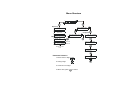
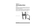
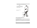
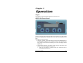
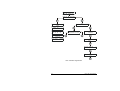
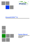
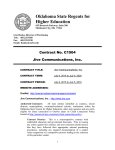
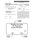
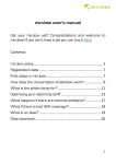
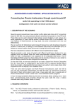
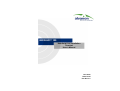
MGW HFIT 100 Handheld FAU Installation Terminal User’s Manual June 2003 P/N 213674 Doc Rev 3.0 PROPRIETARY AND CONFIDENTIAL Copyright © 2003 Alvarion Ltd. All rights reserved. The information contained herein is proprietary and confidential and is intended only for the persons to whom it was transmitted by Alvarion Ltd. Any reproduction, in whole or in part, or the divulgence of any of its contents, without the prior written consent of Alvarion Ltd., is prohibited. Alvarion Ltd. shall not be deemed to make any representation or warranty as to the accuracy or completeness of the information contained herein. Information in this product description is subject to change without notice. HFIT-100 Quick Start Guide 1. Disconnect FAU power. 2. Open FAU bottom cover. 3. Connect HFIT-100 cable to FAU communication connector. 4. Connect FAU power. 5. Fasten HFIT-100 to wrist using the Velcro straps. 6. Select VERIFY & DEFINE - FAU PROPERTIES and configure SU number and target RPU/RPC ID number. 7. Reset the FAU. 8. To download frequency tables, select VERIFY & DEFINE - FREQUENCY TABLE, then select DOWNLOAD TO FAU. FAU resets automatically. 9. Select INSTALL & MEASURE: • During tracking, align FAU for best possible RSSI and CRC results. • Go off-hook, and fine-align FAU for best WER in active state. 10. Disconnect from FAU, and close its bottom cover. Communication Connector Bottom Cover HFIT-100 Cable Phone & Power Cables Menu Structure Monitoring FAU PROPERTIES FREQUENCY TABLE STATE IS: SPAN STATE IS: TRACKING Configuration UPLOAD FROM FAU DOWNLOAD TO FAU TRACK RSSI-65DBM CRC CRC 24 24 24 Values: Best Average Worst TID NUMBER 1234876 STATE IS: ACTIVE ACT RSSI -65DBM WER DL H 00000 RSSI Value ENTER SU NUMBER 1001 WER Value Downlink Time Slot in Use ENTER RPU NO 010223** Parameter Selection RESET FAU-UPDATE YqN 1. Move cursor to digit: 2. Change digit: 3. Continue to next digit 4. When done, press to confirm Table of Contents Chapter 1. Introduction ..................................................................................1-1 Scope ....................................................................................................................... 1-1 Functional Description .............................................................................................. 1-2 Chapter 2. Preparation for Operation ............................................................2-1 Scope ....................................................................................................................... 2-1 Connecting the HFIT-100 to FAU.............................................................................. 2-1 Disconnecting the HFIT-100 ..................................................................................... 2-2 Chapter 3. Operation .......................................................................................3-1 Scope ....................................................................................................................... 3-1 HFIT-100 Front Panel ............................................................................................... 3-1 Starting HFIT-100 Operation..................................................................................... 3-2 HFIT-100 Menu Organization.................................................................................... 3-3 VERIFY OR DEFINE Submenu ................................................................................ 3-5 FAU PROPERTIES Function............................................................................ 3-5 FREQUENCY TABLE Function ........................................................................ 3-6 INSTALL & MEASURE Function............................................................................... 3-7 HFIT-100 User’s Manual i Chapter 1. Introduction Scope This manual covers the operation of the Handheld FAU Installation Terminal, HFIT-100. HFIT-100 is a dedicated handheld terminal that enables rapid and efficient installation and configuration of the Fixed Access Units (FAU’s) used in the MultiGain Wireless (MGW) system. The FAU serves as the MGW subscriber’s access unit. FAU characteristics and capabilities, and detailed installation and configuration procedures, are explained in the MultiGain Wireless System Manual. This manual assumes that the HFIT-100 operator is thoroughly familiar with the FAU installation and configuration procedures, and with all the applicable safety precautions. Velcro Straps Terminal Body HFIT-100, General View Connection Cable to FAU HFIT-100 User’s Manual 1-1 Functional Description The HFIT-100 is a compact, low weight unit, suitable for outdoors use, that can be attached with two Velcro straps to the operator’s wrist. The HFIT-100 connects to the FAU communication connector through a 2 m (6 ft) long cable terminated in a 9-pin D-type male connector. The same cable is used to provide power to the HFIT-100 (the HFIT-100 does not include any internal battery, and its program is stored in firmware). The HFIT-100 communicates with the FAU through an asynchronous interface. After being connected to the FAU, the HFIT-100 automatically identifies the management protocol used by the FAU to which it is connected (DMON for FAU’s using software versions up to 10.44, and EMON for higher versions), and starts communicating with the FAU. In case the FAU is engaged in a management (RMON) session through the radio link, the HFIT-100 enables the user to disconnect the session and take control over the FAU. The HFIT-100 can be used to perform the following activities: Reading of the FAU unique terminal identification (TID) code. Parameter configuration: this includes the assignment of a subscriber number (SU), and the identification code of the target RPU/RPC unit. To enable the changing of parameter values, the HFIT-100 automatically sends the level 1 password to the FAU, and ends the session after each parameter change. To store the updated parameter values in the FAU nonvolatile memory, the HFIT-100 can reset the FAU (provided the operator confirms this action). Upload frequency tables from a FAU, and download the stored tables to other FAU’s. After being loaded with new frequency tables, the FAU is automatically reset. Performance and status monitoring: this includes the display of the FAU state (span/tracking/active), the Receive Signal Strength Indication (RSSI), CRC errors, downlink Word Error Rate (WER), and the time slot used for communication with the RPU/RPC. Using the RSSI, the operator can rapidly align the FAU for best reception, and can then check and improve the alignment using the measured CRC and WER values. All the operations are performed using a simple, menu-driven user interface. The user interface includes an LCD with two rows of 16 characters, and a basic control panel that includes four navigation keys (up/down/left/right arrows), and one confirmation key. The operator can adjust the LCD contrast for optimum viewing. 1-2 HFIT-100 User’s Manual Chapter 2. Preparation for Operation Scope This Chapter provides instructions for preparing the HFIT-100 for operation. To operate the HFIT-100, it is necessary to connect it to the FAU. The activities described in this Chapter require familiarity with FAU installation and operation procedures, covered by the FAU Installation and Operation Manual, included in the MGW System Manual. WARNING The installation procedures described in this Chapter must be performed by authorized personnel, aware of the hazards involved in the installation of communication equipment. For safety information, refer to the FAU Installation and Operation Manual, included in the MGW System Manual. Connecting the HFIT-100 to FAU Before starting, make sure the PCU is not connected to power, and disconnect the cable between the FAU and the PCU, to prevent the supply of power to the FAU from the internal backup battery of the PCU. Unscrew the two screws that fasten the bottom cover to the FAU case, and then carefully remove the bottom cover. Refer to the following figure, and connect the HFIT-100 cable to the internal communication connector of the FAU. The communication connector is a 9-pin female connector; its position may vary somewhat, depending on the exact FAU model. When you are ready to start operation, reconnect the cable between the FAU and the PCU, and then connect the PCU power cable to the designated mains outlet, and turn the PCU on. HFIT-100 User’s Manual 2-1 The FAU and the HFIT-100 are powered as soon as power is provided by the PCU through the connected cable. Refer to Chapter 3 for normal HFIT100 power-up indications, and operating instructions. NOTE If it is necessary to disconnect the HFIT-100 and then reconnect it to the FAU, wait at least 5 seconds before reconnecting. Connection of HFIT-100 Cable to FAU Communication Connector Bottom Cover HFIT-100 Cable Phone & Power Cables Disconnecting the HFIT-100 After completing the initial configuration and alignment activities, disconnect the HFIT-100 cable from the FAU. Now connect cables to the FAU in accordance with the FAU Installation and Operation Manual, and then reinstall the bottom cover on the FAU case (note the polarization slot on the cover). Fasten the cover with the two captive screws. Do not exert excessive force when tightening the screws, to prevent damage to FAU. 2-2 HFIT-100 User’s Manual Chapter 3. Operation Scope This Chapter provides operating instructions for the HFIT-100. HFIT-100 Front Panel The HFIT-100 front panel includes the LCD and five buttons. The LCD includes two rows that display either a selection menu, or the name of a parameter and its value. The buttons are used as follows: The right4and left3arrows are used to move the cursor (displayed as an underline) within a display row. In addition, pressing both the right4and left3arrows at the same time enables you to enter the display contrast adjust mode. The functions of the uptand downuarrows change in accordance with the type of information displayed on the LCD: When the LCD displays a selection menu, the arrows are used to move between the two rows. HFIT-100 User’s Manual 3-1 When the LCD displays a parameter and the cursor is located under a digit, the uptarrow is used to increment the value and the downuarrow is used to decrement. The En button is used to confirm the selected parameter or the execution of the selected action (displayed on the LCD). For your convenience, you can attach the HFIT-100 to your wrist by means of the two Velcro straps, and operate it with one hand. Starting HFIT-100 Operation The HFIT-100 starts operating as soon as it starts receiving power from the FAU to which it is connected. After power-up, the HFIT-100 displays for a short time INNOWAVE, INNOWAVE followed by the software version. After this message, the display shows ACQUIRE COMM, COMM and a moving dot appears in the second row. At this stage, the HFIT-100 tries to establish communication with the FAU: After communication is established, the HFIT-100 displays the main screen, used to select the function performed by the HFIT-100. If when the HFIT-100 is connected, the FAU is engaged in a management session through the radio link, it will not accept HFIT-100 request for communication. In this case, the HFIT-100 notifies the user and prompts for action: RMON MAY BE IN USE DISCONNECT YqN The user can disconnect the ongoing session and take control over the FAU by moving the cursor under Y and then pressing En. The default selection is N, meaning that the user should wait until the session is ended and then try to reconnect. NOTE When the RMON MAY BE IN USE message is displayed, it is recommended to disconnect the HFIT-100, and then reconnect after one or two minutes. At this time, the FAU should be available for communication. The same message can also appear in case the HFIT-100 cannot establish communication with the FAU. Therefore, if the message appears again after connecting for the second time and the disconnect command does not result in the display of the main screen, check that the cable is properly connected to the FAU. 3-2 HFIT-100 User’s Manual In case the FAU receives a management (RMON) request through the radio link while the HFIT-100 is connected to it, it stops the communication with the HFIT-100. In this case, the HFIT-100 displays the following prompt: RMON IN USE DISCONNECT YqN You can wait until the remote session is over, or select Y to disconnect immediately and regain control over the FAU. HFIT-100 Menu Organization The main screen, used to select the activity performed by the HFIT-100, offers two options: Parameter configuration (VERIFY OR DEFINE). After selecting this option, the HFIT-100 displays a submenu for selecting between the FAU parameters (reading of the FAU TID, and selection of the subscriber number (SU) and RPU/RPC ID number), and frequency table transfers (uploading and downloading). Performance monitoring (INSTALL & MEASURE). This includes the display of the FAU state, and the main performance parameters in each state. The selection between the two functions is made by pressing the uptor downuarrows to move the cursor in the appropriate row, and then pressing En to confirm the selection. The following figure shows the HFIT-100 menu organization. HFIT-100 User’s Manual 3-3 OPENING SCREENS (AFTER POWER-UP) VERIFY OR DEFINE INSTALL& MEASURE STATE IS: SPAN FAU PROPERTIES FREQUENCY TABLE STATE IS: TRACKING TRACK RSSI-65DBM CRC 24 24 24 UPLOAD FROM FAU DOWNLOAD TO FAU TID NUMBER 1234876 STATE IS: ACTIVE ACT RSSI -65DBM WER DL H 00000 ENTER SU NUMBER 1001 ENTER RPU NO 010223** RESET FAU-UPDATE YqN HFIT-100 Menu Organization 3-4 HFIT-100 User’s Manual VERIFY OR DEFINE Submenu After selecting the VERIFY OR DEFINE function, the HFIT-100 displays a submenu for selecting the desired activity. Use the following procedure: Parameter Procedure FAU PROPERTIES Use to define FAU properties. Bring cursor to this row and press En to continue. FREQUENCY TABLE Use to perform frequency table transfers. Bring cursor to this row and press En to continue. FAU PROPERTIES Function After selecting the FAU PROPERTIES function, use the following procedure: Parameter Procedure TID NUMBER Displays the unique Terminal Identification (TID) number of the FAU, which is assigned at the factory, and is stored in FAU hardware. The TID includes eight hexa digits. This number should be recorded for reference. After reading the TID, press En to continue. ENTER SU NUMBER Used to enter the FAU subscriber identification number in the MultiGain Wireless System. This is a number in the range of 1 to 1024. To enter the desired number: • Bring the cursor to the first digit with the right4and left3arrows, and then press either the uptor downuarrows until the desired digit is displayed. • Move the cursor to the next digit, and repeat the procedure. • When the correct number is displayed, press En to continue. If the number is not within the allowed range, you will see an error message: wait a few seconds for the message to disappear, and then correct the number and press En again. HFIT-100 User’s Manual 3-5 Cont’d Parameter Procedure ENTER RPU NO Used to enter the identification number of the RPU or RPC that will serve the FAU unit. This number has eight hexa digits: by default, the last two digits are replaced by **, to indicate that the FAU will try to use any RPU/RPC that can be properly received, provided its first six digits match your entry. If necessary, you can enter a specific RPU/RPC number. To enter the desired number, use the procedure described above for the SU number. RESET FAU-UPDATE Used to update the FAU memory with the new parameters entered by you. The updating is performed by sending a reset command: bring the cursor under Y and then press En. You will see the power-up screen. If you select N, the new parameters are lost. FREQUENCY TABLE Function The frequency table used by the FAU is normally downloaded by means of the Handy FAU Installation Terminal, HFIT-2000. The FREQUENCY TABLE function enables you to copy (upload) the frequency table used by an operating FAU and then download this table to other FAU’s. The frequency table is stored in the non-volatile memory of the HFIT-100, and therefore remains available after the HFIT-100 is disconnected from the FAU. After selecting the FREQUENCY TABLE function, use the following procedure: Parameter Procedure UPLOAD FROM FAU Before using the DOWNLOAD TO FAU option, connect the HFIT-100 to a FAU storing the required frequency table, and load the required frequency table from the FAU by selecting the UPLOAD FROM FAU option. Before pressing En, carefully check that the cursor is in the UPLOAD FROM FAU row, because downloading the wrong table to an operating FAU will cause it to stop providing service (service can be restored only after reloading the FAU with the correct table). When ready, press En: after the frequency table is successfully loaded in the HFIT-100 memory, the HFIT-100 displays again the main screen 3-6 HFIT-100 User’s Manual Cont’d Parameter Procedure DOWNLOAD TO FAU Use this option only after the HFIT-100 has been loaded with the required frequency table. To downloading the stored frequency table to the FAU, move the cursor to the DOWNLOAD TO FAU row and then press En to continue. After the downloading is completed, the FAU is automatically restarted. After restarting, the HFIT-100 displays again the main screen INSTALL & MEASURE Function After selecting the INSTALL & MEASURE function, the HFIT-100 starts monitoring the FAU state. The displayed information changes in accordance with the FAU state: SPAN. At power-up, the FAU operates in the SPAN mode. In this mode, the FAU analyzes the current network conditions: identifies the radio port units (RPUs/RPCs) that can be received at its location, and records the corresponding receive signal levels and RPU/RPC time slot occupancy. The FAU selects one of the RPUs/RPCs for which the receive level exceeds a specific threshold, and its time slot occupancy is minimal, to ensure optimal distribution of traffic loading within the system. Only an RPU/RPC having an ID number within the range specified by means of the ENTER RPU NO parameter will be selected. SCAN RANGE. The SCAN RANGE mode is a single-time session between the FAU and the selected RPU/RPC, used to analyze the range between the FAU and the RPU/RPC, for appropriate gain control. The time required for performing this activity is 1 to 10 minutes. The result is the incorporation of the FAU into the network through the selected RPU/RPC. TRACKING. Once incorporated in the network, the FAU operates in the TRACKING mode, except when engaged into an active call. In the TRACKING mode, the FAU continues to track the signals received from the selected RPU/RPC, as well as the signals from the other RPUs/RPCs it is authorized to use. A few seconds after the FAU enters the TRACKING mode, the HFIT-100 starts displaying the following information: RSSI: the average Received Signal Strength, in dBm. CRC: Cyclic Redundancy Code violations. The three displayed numbers correspond to the minimum, average and maximum number of violations during the measurement period. HFIT-100 User’s Manual 3-7 The displayed data is automatically updated after each measurement interval. You can use the displayed RSSI and CRC to align the FAU in the direction that yields the best results. ACTIVE. The FAU enters the ACTIVE mode when the subscriber goes off-hook (for initiating an outgoing call), or in response to an incoming call. At the call completion, the FAU remains ACTIVE for one minute, and then returns to the TRACKING mode. After the FAU enters the ACTIVE mode, the HFIT-100 starts displaying the following information: RSSI: the average received signal strength, in dBm. 3-8 WER: word error rate for the downlink direction (five digits). DL H: the letter following DL indicates the time slot assigned to the FAU. HFIT-100 User’s Manual