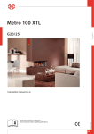
1
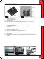
English
Apollo80
Instructionsforinstallation(GB / IE)
959.011.03.uK
Pleaseretainthisdocumentcarefully
1 UK
A p o l l o 80 -
i n s t r u c t i o n f o r i n s ta l l at i o n
Contents
English
Foreword
1. Introduction
2. EC Declaration of Conformity
3. SAFETY
3.1 General
3.2 Regulations
3.3 Precautionary measures / safety instructions regarding installation
4. Instructions
5. Unpacking
6. Installation
6.1 Regulations
6.2 Gas type
6.3 Gas connection
6.4 Positioning the appliance
6.5. Flue gas discharge / combustion air supply system
6.6 Building the chimney breast
6.7 Installing the control box
6.8 Adjusting the appliance
6.9 Arranging the logs
6.10 Glass window
7. Wireless remote control
7.1 Receiver
8. Final inspection
8.1 Gastightness
8.2 Gas pressure/pre-pressure
8.3 Igniting the pilot and main burner
8.4 Flame effect
9. Maintenance
10. Completion
11. Troubleshooting
Annex 1
Annex 2
Annex 3
Components supplied
Technical data
Spare parts
page
2
3
3
3
3
3
3
4
4
4
4
4
4
5
6
9
10
10
11
13
15
15
16
16
16
16
16
17
18
18
20
21
21
Foreword
As manufacturer of gas heating appliances, DRU develops and produces products to meet the highest possible
quality, performance and safety requirements.
As a result of which the user is able to enjoy using your appliance for years to come.
This appliance is CE marked; it complies with the essential requirements of the European Appliance Directive.
The appliance is supplied with two manuals: the installation manual and the user manual.
You the installer should be professionally skilled in the field of decorative gas heating.
The installation manual gives you all the information you will need to be able to install the appliance in such a way
that it works correctly and safely.
This manual deals with the installation of the appliance and the appropriate regulations. It also includes the technical data for the appliance and information on maintenance and troubleshooting.
Please read and use this installation manual carefully.
In the manuals the following symbols are used to denote important information:
➠What to do
!TipSuggestions and recommendations
!N.B.These instructions are important to avoid possible problems during installation and/or use.
N.B.These instructions are important to avoid fire, personal injury or other serious damage.
Once you have completed the installation you are to hand both the user manual and this installation manual to the user.
UK 2
apollo
1.
80 -
i n s t r u c t i o n f o r i n s ta l l at i o n
Introduction
The Apollo 80 is a closed atmospheric gas heating appliance. A closed appliance does not extract the combustion
air from the living environment, but from outside. This is done by means of a combined flue gas discharge system
/ combustion air supply system. In this concentric system, the outer pipe functions as the air supply and the inner
pipe functions as the flue gas discharge.
The safe operation of the appliance is guaranteed by the use of a second thermocouple fitted to the main burner.
This system can be installed through the wall or through the roof.
The appliance is built in a chimney breast. For this, DRU has a number of chimney breasts in its range. In order
to reach a proper heat discharge, the chimney breast must be ventilated. DRU is able to supply various ventilation
elements.
The appliance is supplied with a wireless, battery powered remote control.
2.
EC Declaration of Conformity
English
We hereby declare that the design and construction of the decorative gas heating appliance marketed by DRU conforms with the essential requirements of the Gas Appliance Directive.
This declaration will be rendered invalid should the appliance be altered in any way without the written consent of
DRU.
Product:
Decorative gas heating appliance
Type:
Apollo 80
Applicable EC Directives:
90/396/EEC
Applicable harmonised standards:
NEN-EN-613, NEN-EN-613/A1
In-house measures guarantee that serially produced appliances always conform with the essential requirements of
the current EC Directives and the applicable standards.
R. Gelten
General manager
DRU VERWARMING B.V.
Postbus 1021, 6920 BA Duiven
Ratio 8, 6921 RW Duiven
www.dru.nl
3.
SAFETY
3.1 General
N.B.
-Please read this chapter on safety carefully before commencing installation or maintenance;
-Always observe universal regulations and the precautionary measures / safety instructions in this manual.
3.2 Regulations
The appliance should be installed in compliance with current national, local and constructional (installation) regulations.
3.3 Precautionary measures / safety instructions regarding installation
Observe the following precautions / safety regulations precisely:
➠You may only install and/or service this appliance if your are a qualified installer skilled in installing decorative gas fires;
➠do not adjust the appliance in any way;
➠Non-combustible and heat-resistant materials should be used to construct the chimney breast, its rear wall, the interior and the top of the chimney breast;
➠the minimum internal dimensions required for the chimney breast must be taken into account;
➠the chimney breast should be ventilated by vents with total free vent area of 200 cm2;
➠only use the flue /combustion air supply systems supplied by DRU;
➠use the wall brackets supplied to mount the appliance;
➠do not install the appliance flat against the back wall;
➠leave the space between the feet free;
➠do not cover and/or pack the appliance with an insulating blanket or any other material;
➠Keep combustible objects and/or materials at a minimum distance of 500 mm from the appliance.
➠only use the log set supplied;
➠arrange the logs exactly as described;
➠leave a space around the pilot burner;
➠make sure thermocouple 2 and the space around it are kept free;
➠avoid any dirt in the gas pipes and connections;
3 uk
A p o l l o 80 -
i n s t r u c t i o n f o r i n s ta l l at i o n
➠test the gastightness of all connections before use;
➠use heat-resistant electrical connection materials;
➠install the electrical connections away from the appliance;
➠ replace torn or broken panes;
➠avoid blocking the explosion hatches;
➠ensure the explosion hatches on top of the heater are right on their seats, before you close the chimney breast;
➠do not ignite the appliance until installation has been completed.
4.
Instructions
To ensure the appliance works correctly and safely, always take the following points into consideration during installation:
English
➠place the control box supplied as low as possible;
➠ensure the ignition wire does not lie across the receiver;
➠ensure the ignition wire does not touch or cross the aerial;
➠to avoid weakening the spark ensure the ignition wire does not touch anything metal;
➠if the appliance is to be built in flush with the wall, finish the edges neatly;
➠do not plaster over the flanges;
➠avoid damaging the glass when removing/fitting the window pane;
➠to prevent dirt burning into the glass, make sure it is clean before use.
➠ make sure that the wires of thermocouple 2 cannot come into contact with hot parts.
5.
Unpacking
Please take the following points into consideration when unpacking the appliance:
➠Check the appliance for transit damage;
➠Contact DRU Service if necessary.
Once the packaging material has been removed, you should have the following components:
- Socket spanner: You will find this in the space between the assembly frame and the combustion chamber;
- Trimmings: These are in the same space.
Once you have removed the glass pane you can remove the box of components from the combustion chamber.
!N.B.Be careful not to damage the glass when removing/fitting the window pane.
➠Remove the window as described in paragraph 6.10.1;
➠Take the box of components out of the combustion chamber.
Annex 1 / Table 4 specifies the components you should have once everything has been unpacked.
➠Contact DRU Service if after unpacking the appliance you do not have all the components;
➠Dispose of the packaging in an appropriate manner.
6.
Installation
Please read the manual carefully to ensure that once installed the appliance will work correctly and safely.
!N.B.Install the appliance in the order described in this chapter.
6.1 Regulations
- Observe the current applicable (installation) regulations;
- Observe the regulations/instructions laid down in this manual.
6.2 Gas type
The type plate specifies the type of gas, gas pressure, and the country this appliance is intended for. The type plate
is on a chain and that is where it should stay.
N.B.Check that the appliance is suitable for the local gas type and pressure.
6.3 Gas connection
The gas connection should have a gas tap located near the appliance.
N.B.Prevent any dirt getting into the gas pipes or connections.
The following requirements apply for the gas connection:
➠the size of the gas pipe should be such that no pressure loss can occur;
➠the gas tap must be CE marked;
➠the gas tap should be accessible at all times;
➠Do not twist the gas tap when connecting the gas pipe.
UK 4
80 -
Apollo
i n s t r u c t i o n f o r i n s tA l l At i o n
6.4Positioningtheappliance
Positionthefireasfollows:
N.B.
➠
➠
➠
➠
➠
➠
➠
!N.B.
➠
- Keep combustible objects and/or materials at a minimum distance of 500 mm from the appliance.
- Do not adjust the appliance in any way.
Determine the position of the appliance;
Create a gas connection in the appropriate position; see section 6.3 for details;
Create a duct for the flue / combustion air supply system, with the diameter shown below; see section 6.5 for details;
Ø160 mm for a wall duct of incombustible material;
Ø 250 mm for a wall duct of combustible material;
Ø160 mm for a roof duct of incombustible material;
Ø 250 mm for a roof duct of combustible material.
- Allow for the depth of the appliance (see Fig. 2) (The minimum depth at the Apollo is 450 mm);
- Allow for the build-in height; this will depend on the height of the adjustable feet (see Fig. 1a).
Move the appliance into its intended position.
Thegascontrolblockismountedontotheburnerplateatthebottomoftheappliance.Thisshouldberemovedand
placedinthecontrolboxlater.Seesection6.7forinformationonhowtofitthegascontrolblock.
Commenceasfollows:
Disconnect the hoses from the gas control block (flexible gas hose, aluminium pilot pipe and thermocouple 1);
Caution The red wire of thermocouple 2 must remain connected to the gas control. Fig. 1b shows how the wires are connected
to the thermocouple.
Unscrew the self-tapping screw in the burner plate and remove the gas control block.
➠
Carefully unwind the red and black wires of thermocouple 2.
➠
Lay the gas control together with the wires of thermocouple 2 in the direction of the control box.
➠
N.B. - Avoid dirt in the hoses;
- Avoid kinks in the hoses.
Unroll the hoses towards the control box;
➠
Unroll the ignition wire towards the control box.
➠
English
➠
995
813
Top view
50
448
192
min. 160
max. 185
504
min. 910
max. 935
15
Front view
Side view
Apollo 80
Fig. 1a
Fig. 1b
min 450 mm inside
min 1450 mm inside
max 100 mm
min
1350 mm
inside
b
A-A
Total
ventilation
200 cm2
c
A
A
508
min
150 mm
=
817
=
Fig. 2
94
-12
38c
Control box
b
Maximal
plaster line
Maximal
plaster line
c
5 UK
A p o l l o 80 -
!N.B.
➠
➠
➠
N.B.
➠
The type plate should be connected to the chain.
Lay the chain with the type plate facing the control
box;
Adjust the height of the appliance;
Using a spirit level to ensure it is absolutely level.
- Do not install the appliance flat against the back
wall;
- Leave the space between the feet free;
- Do not cover and/or pack the appliance with an insulating blanket or any other material.
Secure the appliance against the wall using the wall
brackets and rawplugs supplied (see Fig. 3).
i n s t r u c t i o n f o r i n s tA l l At i o n
Wall brackets
38c-1292
Fig. 3
Explosion by-pass valves
6.5Fluegasdischarge/combustionair
supplysystem
6.5.1General
English
TheapplianceisoftheC11/C31type.
Theapplianceisconnectedtoacombinedfluegas
discharge/combustion air supply system, hereafter
referredtoastheconcentricsystem.
Thepassagetotheoutsidecanbemadewithawall
duct(seesection6.5.2)orwitharoofduct(seesection6.5.3).
Ifnecessary,youcanalsouseanexistingdischarge
channel(seesection6.5.4).
N.B.
- Only use the concentric system supplied by DRU
(Ø100 / Ø150 mm). This system was tested in combination with the appliance; DRU cannot guarantee
a proper and safe operation of other systems and
cannot accept liability for these systems;
- For connecting to an existing chimney flue you
should only use the installation set supplied by
DRU.
Fig. 4a
The concentric system is constructed from (the dischargestumpof)theappliance.
Ifstructuralcircumstancesrequirethattheconcentricsystemisplacedfirst,theappliancecanlaterbe
connectedwithatelescopicpipepiece.
6.5.2Applicationwithwallduct
6.5.2.1 Construction of concentric system with
wallduct
Fig. 4b
Theconcentricsystemwithwallducthastocomplywiththefollowingconditions:
➠
➠
➠
➠
First, a concentric pipe of at least 1 meter should be connected vertically to the appliance;
The total vertical pipe length can have a maximum of 4 meters;
After the vertical part a bend of 90° is connected;
When using a minimum 1 up to maximum 4 meter vertical pipe length, the total horizontal pipe length may have a
maximum of 3 meters (wall duct not included; see Fig. 4a).
Dependingontheconstructionoftheconcentricsystem,furtheradjustmentsshouldbemadetotheappliance.
Thenext2configurationsareallowedfortheconstruction:
a)aminimum1meteruptomaximum4meterverticalpipelengthincombinationwitha90°bendandawallduct
(i.e.nohorizontalpart;seeFig. 4b).
Whenusingthisconfiguration,youmustsettherestrictionto60mm(forthis,seesection6.8.1).
b)aminimum1meterandmaximum4meterverticalpipelengthincombinationwitha90°bendandamaximum
3meterhorizontalpipelengthandawallduct(seeFig. 4a).
Whenusingthisapplication,youmustremovetheairinletguides.
6.5.2.2Installingtheconcentricsystem
UK 6
apollo
80 -
i n s t r u c t i o n f o r i n s ta l l at i o n
To install the concentric system commence as follows:
➠Construct the system from the (connection stub of the) appliance up.
-Maintain a distance of at least 50 mm between the outside of the concentric system and the walls and/or the ceiling;
If the system is built-into a cove for example, incombustible material should be applied all around;
-Use heat-resistant insulating material for ducts made of combustible material;
-The rosette (mounting inner plate) of the wall duct is too small to seal the Ø 250 mm opening when passing through
combustible material. That is why you should first apply a sufficiently large heat-resistant intermediate plate to the
wall. Then, the rosette is mounted on the intermediate plate.
➠Connect the concentric pipe sections and the bend(s);
➠Fit a clamping strip and silicone sealing ring to every connection;
➠Secure the clamping strip with a self-tapping screw in places which will be inaccessible after installation;
➠Use enough brackets to ensure that the weight of the pipes does not rest on the appliance;
➠Determine the remaining length of the wall duct;
➠Cut the wall duct to size;
!N.B. -Make sure that the right insertion length is maintained;
-Place the wall duct with the groove/folded seam at the top;
-Make sure the horizontal concentric pipe pieces are sloping towards the wall duct, in order to prevent rain water
from entering.
➠Mount the rosette (mounting inner plate); if necessary, on a heat resistant intermediate plate when passing through
combustible material;
➠Attach the wall duct from the outside with four screws in their respective holes.
!N.B.Some heat-resistant isolation materials contain volatile components that will spread an unpleasant smell for a prolonged time; these are not suitable.
English
N.B.
6.5.3 Application with roof duct
6.5.3.1 Construction of concentric system with roof duct
The concentric system with roof duct has to comply with the following conditions
➠The construction of the chosen system has to be allowed. (See the procedure described below);
➠First, a concentric pipe of at least 1 meter should be connected vertically to the appliance.
Depending on the construction of the concentric system, the appliance is set by placing the baffle and/or removing
the air inlet guides.
In the following procedure you can see how the allowability of a concentric system can be determined and which
settings are needed.
➠Determine the following data:
1.The number of bends required (no distinction is made between 45° and 90° bends);
2.The total number of meters of horizontal pipe length;
3.The total number of meters of vertical and/or sloping pipe length (wall duct not included).
With these data and Table 1 you will be able to determine whether the concentric system is allowed.
In Table 2 you can see which setting the appliance needs.
Follow the procedure described below:
➠In the first 2 columns of Table 1, look for the number of bends required and the total horizontal pipe length;
➠In the 3rd column of Table 1, look for the total vertical and/or sloping pipe length.
If you end up in a box with the letter A, B, C, D or E the concentric system chosen by you is allowed.
➠Use Table 2 to determine which conditions apply for the baffle and/or the air inlet guides (for setting see section 6.8);
Examples
To clarify, we will give 2 examples to determine the allowability of a concentric system and the conditions for setting
the appliance.
In Table 1 the route to be followed is indicated by arrows. The result is indicated by means of the red frame of the box.
Example 1
1)2 bends
2)3 meters horizontal
3)8 meters vertical/sloping
→ Construction of this concentric system is allowed.
→ Situation B applies for setting the appliance
7 uk
A p o l l o 80 -
i n s t r u c t i o n f o r i n s ta l l at i o n
Example 2
1)3 bends
2)4 meters horizontal
3)10 meters vertical/sloping
→ Construction of this concentric system is not allowed.
Table 1: Conditions for adjusting the equipment with roof ducts
G20 / G25
total number of
meters of horizontal pipe lengths
total number of meters of vertical and/or sloping pipe lengths
1
2
3
4
5
6
7
9
↓10
11
12
no bends
0
B
C
C
D
D
D
D
E
E
E
E
E
2 bends
0
A
A
B
C
C
D
D
D
D
E
E
E
A
A
B
C
C
D
D
D
D
E
A
A
B
C
C
D
D
D
A
A
B
C
C
D
A
A
B
C
1
2
→
3
4
English
↓8
5
3 bends
0
A
1
A
A
B
C
C
D
D
D
D
E
A
A
A
B
C
C
D
D
D
D
A
A
A
B
C
C
D
D
A
A
A
B
C
C
A
A
A
B
2
3
→
4
E
5
4 bends
0
A
1
A
A
A
B
C
C
D
D
D
D
A
A
A
A
B
C
C
D
D
D
A
A
A
A
B
C
C
D
C
2
3
A
4
A
A
A
B
A
A
A
A
E
5
5 bends
-
n= The situation is not permissible.
Table 2:
Situation
Air inlet guide
Baffle
Dammingg distance
A
NO
NO
OPEN
B
YES
YES
44 mm
C
YES
YES
41 mm
D
YES
YES
37 mm
E
YES
YES
30 mm
6.5.3.2 Installing the concentric system
The roof duct can be used for either a sloping roof or a flat roof.
The roof duct can be supplied with an adhesive plate for a flat roof or with a universally adjustable tile for a sloping roof.
Install the concentric system as follows:
➠Construct the system from the (connection stub of the) appliance up
N.B.-Maintain a distance of at least 50 mm between the outside of the concentric system and the walls and/or the ceiling;
If the system is built-into a cove for example, incombustible material should be applied all around;
-Use heat-resistant insulating material for ducts made of combustible material.
!N.B.Some heat-resistant isolation materials contain volatile components that will spread an unpleasant smell for a prolonged time; these are not suitable.
UK 8
apollo
80 -
i n s t r u c t i o n f o r i n s ta l l at i o n
➠Connect the concentric pipe sections and any necessary bends;
➠Fit a clamping strip and silicone sealing ring to every connection;
➠Secure the clamping strip with a self-tapping screw in places which will be inaccessible after installation;
➠Use enough brackets to ensure that the weight of the pipes does not rest on the appliance;
➠Determine the remaining length of the roof duct;
➠Cut the roof duct to size.
!N.B.Be sure to maintain the correct insertion length.
➠Connect the roof duct to the concentric pipes.
!N.B.-Make sure the universal roof tile fits well against the surrounding tiles;
-Make sure the adhesive flashing sticks to the flat roof properly.
6.5.4 Connection to an existing flue
English
The appliance can also be connected to an existing flue.
A flexible SS pipe is placed in the chimney for discharging flue gases. The surrounding space is used to supply the
combustion air.
The following requirements apply for connection to an existing flue:
-allowed only if the special DRU chimney connection set is used;
-Installation instructions supplied;
-minimum dimensions 150 x 150 mm;
-maximum vertical length 12 metres;
-maximum horizontal length 3 metres;
-the existing flue must be clean;
-the existing flue must not have any cracks or leaks.
6.6 Building the chimney breast
The appliance is designed to be installed snugly into a newly built chimney breast.
There must be sufficient space around the appliance to ensure a good heat distribution.
The chimney breast should be ventilated by vents.
-Use incombustible and heat-resistant material to construct the chimney breast, including rear wall of the chimney
breast;
-The total free vent area of the vents, installed as high as possible, should be at least 200 cm2.
!N.B.When building the chimney breast, the following points should be taken into account (see Fig. 2):
-position of the control box: this should be placed within 850 mm to the left or right of the appliance, as low as possible;
-size of the control box; see section 6.7 Installing the control box;
-position of the vents;
-the size of the glass window so that it can be fitted/removed once the chimney breast has been built;
-protecting the gas control block and hoses from cement and plaster.
!TipThe vents should preferably be created in both sides of the chimney breast: you could use DRU ventilation elements.
➠Check that the concentric system has been installed correctly;
➠Check that the clamping strips have been secured with self-tapping screws in places which will be inaccessible later;
➠Allow sufficient clearance round the appliance in the chimney breast to enable the heat to disperse:
-minimum internal height: 1350 mm;
-minimum internal width: 1450 mm.
➠Do not plaster over the flanges because:
-the heat from the appliance could cause cracks;
-it will then be impossible to remove/fit the glass window.
➠If the chimney breast is of materials similar to stone, or is finished with plaster, it should be dried-out at least 6 weeks
before commissioning, in order to prevent cracks.
N.B.
6.7 Installing the control box
The control box is to be installed as low as possible.
The control box contains various components such as the type plate, the gas control block, and the receiver for the
remote control. (See Fig. 5 for details.)
➠Make a 285 x 194 mm (h x w) opening in the chimney breast;
➠Fit the inner frame (1); to do this unscrew the bolts (5).
!Tip-If the chimney breast is brick, the inner frame can be cemented in during building;
-For a chimney breast of any other material, glue/cement the inner frame in place or fit it with four countersunk
screws.
9 uk
A p o l l o 80 -
➠
➠
N.B.
➠
➠
➠
➠
➠
➠
➠
!Tip
i n s t r u c t i o n f o r i n s tA l l At i o n
Mount the gas control block on the brackets (2) on the inner frame;
Reconnect the hoses to the gas control block.
- Avoid kinks in the hoses;
- Tighten the flexible hose and aluminium pipe making sure they are gastight;
- Screw the thermocouple 1 on by hand first and then;
- then tighten it a quarter turn using a suitable spanner.
Connect the thermocouple1 wiring to the gas control block if necessary; see Photo 1;
Blow through the gas pipe if necessary;
Connect the gas pipe to the gas tap;
Bleed off the air in the gas pipe;
Fit the receiver (3); see section 7.1 for connections;
Fit the type plate (6);
Fit the outer frame with door (4) to the inner frame using the two self-tapping screws (5).
You can position the outer frame in such a way that the door opens to either the left or right.
6.8Adjustingtheappliance
English
Theappliancehastobesetinsuchawaythatitworkscorrectlyincombinationwiththedischargesystem.
Forthatpurpose,abaffleisplacedand/ortheairinletguidesareremoved.Theconditionsforusingawallductare
describedinsection6.5.2.1,andforusingaroofductinsection6.5.3.1.
Caution For Belgium, the condition applies that the primary aeration of the burners has to be changed, if the appliance is used
with gas G25 instead of G20; see section 6.8.3.
6.8.1Baffle(R)
Thebaffle(R)issuppliedseparately.
Itismountedasfollows:
➠
➠
➠
Place the baffle. (see Fig. 6a and 6b)
Use the template supplied to set the distance of the restriction (see Fig. 7) as follows:
- A distance of 30 mm, means that the baffle will be fully closed;
- A distance of 37 mm is set by means of the template;
- A distance of 41 mm is set by means of the template;
- A distance of 44 mm is set by means of the template;
- A distance of 60 mm is set by means of the template;
Fix the baffle by using the socket cap screw (U).
6.8.2Airinletguides(L)
Theairinletguides(L)arelocatedatthebottom(side)ofthetrayaroundtheburner.
Removethemasfollows;seeFig. 8:
➠
➠
➠
➠
Remove the tray surrounding the burner (M);
Unscrew and remove the self-tapping screws (N);
Remove the air inlet guides;
Replace the tray round the burner.
Damper
37
1
4
socket-head screw
6
Fig. 6a
5
41
2
Damper
44
60
38c-1078
3
Fig. 5
U K 10
Fig. 6b
38c-1269
Fig. 7
80 -
Apollo
i n s t r u c t i o n f o r i n s tA l l At i o n
6.8.3Primaryaerationoftheburners
Caution Adjusting the primary aeration only applies to appliances used in Belgium.
Whenthetraysurroundingtheburnersisremoved,youcanseethethrottlerings(PaandPb)thataremountedon
thepipesthatarefixedtotheburners(burnerpipes);seeFig. 9.
Theprimaryaerationoftheburnerscanbeadjustedbyrotatingthethrottlerings.
Caution Rotate the throttle ring at the front left (Pb) with its opening towards the pilot flame burner. This throttle ring has only
1 hole with a diameter of 6 mm and 1 with a diameter of 12 mm (see Fig. 9).
Thestepstobetakenaredescribedbelow:
➠
➠
➠
Take the tray surrounding the burners (M) out of the appliance; see Fig. 10a.
Unscrew the socket cap screw (O) of a throttle ring (P), see Fig. 11.
Rotate the throttle ring (P) when using gas G25 in such a way, that the holes with the 7 mm diameter are directly opposite the 15 mm holes in the burner pipe; see Fig. 11.
Screw the socket cap screw (O) into the threaded hole above the 7 mm diameter hole.
Repeat this procedure for the other 3 burner pipes.
Return the tray surrounding the burners (M).
English
➠
➠
➠
6.9Arrangingthelogs
Theapplianceissuppliedwithasetoflogs.
N.B.
Observe the instructions below precisely to avoid unsafe situations.
- only use the log set supplied;
- arrange the logs exactly as described;
- do not cover the pilot burner or the surrounding area;
- make sure that thermocouple 2 and the space around it are kept free from objects (see photo 4c and photo 4d);
- do not cover the slot between the burner tray and the tray surrounding the burner.
Fig. 8
Fig. 9
Photo 1
Photo 2
Photo 3
11 U K
A p o l l o 80 -
Photo 4b
Foto 4c
Foto 4d
English
Photo 4a
Photo 5
Photo 6a
U K 12
i n s t r u c t i o n f o r i n s tA l l At i o n
Apollo
80 -
i n s t r u c t i o n f o r i n s tA l l At i o n
Photo 6c
Photo 6d
Photo 6e
Photo 6f
Photo 6g
Photo 6h
Photo 6i
English
Photo 6b
6.9.1Woodset
The wood set consists of vermiculite (see Fig. 2),
chips(seeFig. 3)andanumberoflogs.
Fill the burner tray with vermiculite; equally spread
the vermiculite (see Fig. 5).
!Caution - You can influence the flame image by moving the
vermiculite, yet
- the burner deck has to remain covered with vermiPhoto 6j
culite in order to prevent that the life expectancy of
the burner is reduced.
Fill the tray around the burner with chips; equally spread the chips (see Fig. 5);
➠
Identify logs A up to E by using Fig. 6a.
➠
!Tip
Use the burn stains on the logs for identification.
➠
13 U K
A p o l l o 80 -
i n s t r u c t i o n f o r i n s tA l l At i o n
English
Photo 7a
Photo 10a
Photo 10b
Photo 10c
Photo 10d
Photo 10e
Photo 10f
Photo 7b
Photo 8
Photo 9
U K 14
80 -
i n s t r u c t i o n f o r i n s tA l l At i o n
Photo 11
➠
➠
Photo 12
First place log A as indicated in Fig. 4a en 4b.
Place log A up to E over the burners (see Fig. 6b up to 6j);
English
Apollo
Caution - Make sure log A is lying correctly in relation to the ridge, see the arrow.
Next, you should place log B;
➠
Caution Make sure log B is lying correctly in relation to the ridges.
Proceed with logs C, D and E.
➠
Caution - The logs should be placed exactly as indicated in Fig. 6j;
- The logs should not completely cover the burner deck, because:
- the main burner will not ignite properly; which could result in unsafe situations;
- the appliance will become filthy more quickly, as a result of soot;
- the flame image may be affected.
Thelogsetconsistsofvermiculite(seePhoto 2),chippings(seePhoto 3)andafewlogs.
➠
!N.B.
➠
➠
!Tip
➠
➠
Fill the burner tray with the vermiculite, spreading it out evenly.
- You can alter the flame effect by moving the vermiculite but;
- the burner cap must remain covered by vermiculite to help preserve the useful life of the burner.
Fill the tray surrounding the burner with chippings; spreading them out evenly;
Identify the logs A - D using Photo 4 for reference.
The burn marks on the logs will help you identify them.
Place block A around the (main) burner. This can only be done in one way (see Photo 5);
Install block B, C and D (see Photo 6, 7 and 8).
6.10Glasswindow
Oncethelogshavebeenarrangedtheglasswindowcanbefittedasdescribedbelow.
6.10.1Removingtheglasswindow
Removetheglassframeinaccordancewiththefollowinginstructions(seePhotos 7 to 12):
➠
➠
➠
Remove the vertical decorative strips on the left and right of the glass frame by pushing the lip at the top of each strip
up, tilting the top of the strip parallel with the glass frame, and then removing the strip.
Remove the horizontal decorative strip by gripping it with 2 hands in the slot and lifting it out.
Unscrew the 4 self-tapping screws in the bottom strip using the socket spanner supplied with the appliance.
Loosen the 3 self-tapping screws in the fastening strips on both sides 2 turns.
!N.B.
Do not remove the self-tapping screws: leave them in place in the fastening strips.
➠
➠
➠
➠
➠
Push the 2 top wedges (left and right) down as far as possible.
Push the 2 bottom wedges upwards as far as possible.
Press the two fastening strips outwards with your hands as far as possible to avoid damage to the sealing cord.
Take hold of the top and bottom handgrips and lift the glass frame.
Pull on the bottom handgrip to tilt the glass frame in its mounting towards you and, at the same time, pull the top of
the glass frame towards you as far as possible.
➠
15 U K
A p o l l o 80 -
i n s t r u c t i o n f o r i n s ta l l at i o n
!N.B. -Make sure you hold the upper handgrip firmly. If you let go of the handgrip then the glass frame could fall inwards
and cause severe damage to both the glass and the appliance;
-Make sure that you lift the glass frame out of its mounting as straight as possible to avoid damage to the paintwork
and the sealing cord.
➠Gently allow the glass frame to drop at an angle until it can be removed entirely from the mounting.
6.10.2 Fitting the glass window
The glass frame is fitted by using the above procedure, in reverse order.
!N.B.
- Avoid/remove fingerprints on the glass, since otherwise they will burn into the surface;
-The self-tapping screws must not be over-tightened, since otherwise they could break or strip the thread:
tight=tight;
- Replace the fastening strip if the sealing cord has come loose.
Pay attention to the following when fitting the glass frame:
➠Begin by checking that the two fastening strips are pressed outwards as far as possible to avoid damage to the sealing
English
cord.
➠Fit the glass frame.
➠Check that the hook at the top of the glass frame is in position in the seating / U-shaped strip.
!Tip
Pull on the upper handgrip to move the glass frame towards you: if it does not move, then it has been fitted correctly.
!N.B.
Fix the glass frame’s bottom strip in place with the 4 self-tapping screws.
➠Push both bottom wedges downwards.
➠Push the top wedges upwards until the sealing cord of both fastening strips press against the glass.
➠Tighten each wedge’s self-tapping screw.
!N.B.
Press on the wedge with your hand to hold it in place while you tighten the screws.
➠Tighten the middle self-tapping screw in each fastening strip.
➠Fit the horizontal decorative strips.
➠Fit the vertical decorative strips.
7.
Wireless remote control
See Chapter 4 of the User Manual, ‘Remote Control’, for details of how to operate the system.
The remote system consists of a remote control system and a receiver.
The procedure for connecting the receiver has been described below; the working of the remote control system has
been explained in detail in Chapter 4, 4.2 of the User Manual 4, 4.2
7.1 Receiver
The receiver must be connected to the appliance before the batteries are inserted.
Do this as follows (see Photo. 13):
➠Slide the brown plug off the lead at the back on the PCB of the receiver;
➠Connect the white plug to the gas control block.
!Tipthe plugs are different sizes and correspond with the connectors.
➠Connect the thermocouple 2 wires to the receiver (see Photo 13, arrows B).
!Tip
-the size of the eye corresponds with the size of the screw;
-the colour of the eye and screw also correspond.
➠ Connect the black wire with the white plug of thermocouple 2 to the receiver (see Photo 13, arrow E).
Caution Make sure that the wires of thermocouple 2 cannot come into contact with hot parts.
➠Connect the ignition wire to the receiver (see Photo 13, arrow A);
➠Connect the power supply:
a)For batteries see section 7.1.1 below;
b)For an adapter:
- connect the adapter to the receiver (see Photo 13, arrow C);
-p
lug the adapter into the wall socket.
U K 16
80 -
i n s t r u c t i o n f o r i n s tA l l At i o n
Photo 14
Photo 13
➠
➠
➠
!N.B.
Place the receiver in the control box:
- Position the receiver as shown in Photo 14.
Bend the aerial out of the clips, see Photo 13, arrow D;
Put the aerial straight up.
- Do not put the aerial too close to the ignition wire and/or metal parts (see Photo 14 for the correct position);
- Do not lay the ignition wire across and/or beside metal parts: this will weaken the spark;
- Do not lay the ignition wire across the receiver: this could damage the receiver;
- Avoid dust accumulating on or in the receiver: cover it during servicing or maintenance.
English
Apollo
7.1.1Fitting/replacingthebatteries
Tofitthebatteries:
➠
➠
➠
➠
!N.B.
➠
➠
!N.B.
Open the flap on the control box;
Take the receiver;
Slide the lid off ;
Fit or remove the 4 penlight (AA size) batteries.
- Avoid short circuits between the batteries and metal objects/components;
- Note the “+” and “-” positions of the batteries in the holder;
- Use alkaline batteries.
Slide the lid back on;
Replace the receiver.
Do not throw batteries in the dustbin, they are considered “domestic chemical waste” and should be disposed of
accordingly.
Photo 15
Photo 16
Photo 17
17 U K
A p o l l o 80 -
8.
i n s t r u c t i o n f o r i n s tA l l At i o n
Finalinspection
Toensuretheapplianceisworkingcorrectlyandsafely,checkthefollowingbeforeuse:
8.1Gastightness
N.B.
!N.B.
➠
All connections must be gastight.
The maximum pressure to which the gas control block may be exposed is 50 mbar.
Test the connections for gastightness.
8.2Gaspressure/pre-pressure
➠
➠
Theburnerpressureisfactoryadjusted;seetypeplate.Itisnotnecessarytotesttheburnerpressure.
Thepre-pressureindomesticinstallationsshouldbetestedhowever,asthiscanvary.
Check the pre-pressure; see Photo 16 for the measuring nipple on the gas control block;
Contact the power company if the pre-pressure is not right.
8.3Ignitingthepilotandmainburner
English
8.3.1Pilot
➠
Test that the pilot ignites properly, see section 0 Remote control:
- the pilot burner should ignite at the first attempt.
➠
Check whether or not the ignition sparks:
a) If not, the ignition wire is probably touching something metal;
b) If it does, there is probably air in the pipes.
➠
➠
Bleed off any air in the pipes and/or;
Move the ignition wire so that it does not touch anything metal.
Ifthepilotdoesnotlight,then
8.3.2Mainburners
Caution The burners should ignite smoothly and should not pop as a result of postponed ignition.
Check the function of the main burners from the standby (pilot flame) position:
➠
- after opening the gas valve, the main burners should burn within a few seconds.
!Tip
When the gas valve is opened, the motor will run; this is audible.
1)Ifthemainburnersdoesnotburn:
➠
➠
➠
➠
➠
Check if button A on the gas control is in the position ON;
Check if the space surrounding the pilot burner is free from objects;
Check the placement of the wood/pebble set.
If necessary, correct the above mentioned faults.
Test the main burner 5x for a good operation.
➠
Check the wiring of thermocouple 2 for:
2)Ifmainburnersignites,butgooutagainafterapprox.22seconds,please:
-
-
-
-
➠
➠
➠
➠
Check if thermocouple 2 is dirty.
Check if thermocouple 2 is positioned correctly in the flame;
see fig. 10.
Check if thermocouple 2 is defective; see chapter 11, table 4
under J7.
Check if the receiver is defective; see chapter 11, table 4
under J8.
If necessary, correct the above mentioned faults.
Test the main burner 5x for a good operation.
15
25
➠
➠
Loosewiring;
Wronglyconnectedwiring;
Short-circuit;
Brokenwire.
Fig 10
U K 18
38C-1894 /0
apollo
80 -
i n s t r u c t i o n f o r i n s ta l l at i o n
8.4 Flame effect
The flame effect cannot really be assessed until the fire has been on for several hours. Volatile elements in paint,
materials, etc., which evaporate during the first hours of use, will initially influence the flame effect.
!N.B.If the chimney breast is of materials similar to stone, or is finished with plaster, it should be dried-out at least 6 weeks
before commissioning, in order to prevent cracks.
➠Check that the flame effect is symmetrical.
An asymmetrical flame effect could be caused by:
-volatile substances evaporating;
-incorrectly arranged logs.
➠Rearrange the logs as necessary.9.
9. Maintenance
ainteThe appliance should
English
be inspected, cleaned and if necessary repaired by a qualified installer with professional
experience of decorative gas fires at least once a year.
The appliance should at least be tested to check it works correctly and safely.
N.B.-Switch off the gas before commencing any maintenance;
-Test the gastightness after any repairs;
-After replacing thermocouple 1 you should first tighten the swivel of the gas control block by hand and then give it
another quarter turn with a suitable spanner.
➠Clean the following components if necessary:
-the pilot burner;
-the combustion chamber;
-the glass
!N.B. -Remove the glass as described in section 6.10
-Remove the deposit on the inside of the glass with a damp cloth or a non-abrasive cleaning product such as copper
polish;
-Avoid/remove fingerprints on the window as they will burn into the glass;
-Replace broken and/or cracked glass.
N.B. If necessary, place back the wood set correctly; see section 6.9.
➠Inspect the flue / combustion air supply system;
➠Test the system as described in chapter 8.
10. Completion
Familiarise the user with the appliance. You should instruct him/her on such things as how to use the appliance and
how it works, how to use the remote control, and about the need for annual maintenance.
-Tell the user to switch off the gas immediately and to contact the installer in the event of a failure / malfunction, to
avoid unsafe situations;
-Show him/her where the gas tap is.
➠Explain how to use the appliance and the remote control;
➠Point out the precautions in the user manual concerning unintended ignition by other remote controls such as car keys
and garage door openers;
➠Point out that when the appliance is used for the first time:
-If the chimney breast is of materials similar to stone, or is finished with plaster, it should be dried-out at least 6 weeks
before commissioning, in order to prevent cracks;
-volatile elements in paint, materials etc. will evaporate the first time the fire is used;
-the fire should preferably be used at the highest setting so that these elements will evaporate more quickly;
-the room should be well ventilated.
➠Hand the user the user manual and the installation manual (the installation manual should be kept near the appliance).
N.B.
19 uk
A p o l l o 80 -
i n s t r u c t i o n f o r i n s ta l l at i o n
11. Troubleshooting
A number of faults which could occur, their possible causes and solutions are shown in the table below:
Table 3: Troubleshooting
Problem
Possible cause
Solution
A. No transmission
(motor doesn’t work)
1.The (new) communication
code between the receiver
and the remote control has
not been confirmed.
1.Press and hold the reset button on the
receiver until you hear 2 bleeps.
After the second, longer bleep, release
the reset button and, within 20 seconds
press / t on the remote control until
you hear an extra long bleep which confirm the new code; see Photo 15.
2. Replace the batteries.
2. Dead batteries.
!N.B.Avoid short circuits between the batteries and metal parts of the appliance.
English
3. Receiver is damaged.
4. Remote control is damaged
3.Replace the receiver and confirm/change
the code (solution 1)
4.Replace the remote control and confirm/
change the code (solution 1)
5. Replace the motor wiring at the valve.
5.Motor wiring broken at the
valve
6.Bent pins on the 8-pin con- 6. Straighten the pins on the 8-pin connector.
nector.
7.If the receiver is surrounded 7. Change the position of the aerial.
by metal, the transmission
range may be reduced.
1.Switch button A on the gas control block
to ON, see Photo 14
2Do not let the ignition wire touch any2Ignition wire lying across
thing metal: This will weaken the spark;
and/or beside metal composee 2 Ignition wire lying across and/or
nents.
along beside metal components.
Replace the ignition wire if necessary.
3. Replace the ignition pen
3. Ignition pen corroded
B. No ignition (spark)
1. Button A is set to MAN.
C. No bleep
1. Receiver is damaged.
2. 60-second delay before the
full restart is not yet finished.
D.One continuous 5 second bleep 1. Loose wiring
(There may be 7 short bleeps 2. Receiver is damaged.
before the 5 second bleep)
3.Bent pins on the 8-pin connector.
4. Magnetic valve is damaged.
5. Thermocouple 2 still too
hot.
E. No pilot
UK 20
1. Air in the pilot pipes.
1.Replace the receiver and confirm/change
the code (solution 1 at A)
2. Wait until the delay time has passed.
1. Connect the wiring correctly.
2.Replace the receiver and confirm/change
the code (solution 1 at A)
3.Straighten the pins on the 8-pin connector.
4. Replace the gas control block.
5. Wait until the thermocouple has cooled down sufficiently.
1.Purge the pipes or restart the ignition
process several times.
2.Wires of thermocouple 1 have 2.Check the polarity of the thermocouple
been cross-connected.
wiring.
3. No spark at the pilot burner. Connect the thermocouple correctly.
3.Check that the ignition wire is not touching anything metal.
Move it if necessary; see Photo 14
Replace the ignition wire if necessary
If necessary, replace the ignition pen
4. Injector is blocked up
4.1 Clean the injector
4.2If necessary, replace the injector
80 -
i n s t r u c t i o n f o r i n s ta l l at i o n
F.Electronics keep sparking when 1. Receiver is damaged.
the pilot burner is burning
1.Replace the receiver and confirm/change
the code (solution 1 at A)
1. Thermocouple 1 does not G.Pilot burner is burning but
function.
the magnetic valve closes
after approx. 10 seconds or
when the appliance gets too
hot
1.1Measure the voltage with a digital multimeter, set to mV range, by connecting the
wires to the cable terminal. The cable terminal is on the outside, right next to the
magnetic nut, see 2: Batteries (almost)
dead (see Photo 17). The voltage should
be at least 5mV within 20 seconds. This
must not be any lower when the appliance is hot.
If the voltage is too low then
- the thermocouple should be moved so
that it is in the flame more, or
- the thermocouple should be replaced.
1.2 Check the size of the pilot.
Adjust the pilot if it is too low.
1.3Check the wiring between the thermocouple and the receiver.
Replace the wiring if necessary.
2. Replace the battery.
English
apollo
2. Batteries (almost) dead
1. Batteries (almost) dead
H.There are short bleeps but
no sparks and is no sound
/ ticking can be heard of the
magnet opening the valve
1. Replace the batteries.
I.Pilot burner is on but there is 1. Button A is set to MAN.
no gas flow to the main burner
2.Appliance is set to pilot
mode.
3. Pre-pressure is too low.
1.Switch button A on the gas control block
to ON, see Photo 14
2.Increase the flame height by pressing /
t button on the remote control.
3. Test the pre-pressure
Contact the power company if necessary.
4. Replace the gas control block.
4. Magnetic valve is damaged.
J.Main burners ignites, but go 1.Wiring of thermocouple 2 is
loose.
out again after approx. 22
2.Wires of thermocouple 2
seconds.
have been cross-connected.
3.Short-circuit in the wiring of
thermocouple 2.
4.Broken wire in the wiring of
thermocouple 2.
5.Thermocouple 2 is dirty.
6.Thermocouple 2 is not positioned correctly in the flame
(see fig. 23.)
7. Thermocouple 2 is defective.
8. Receiver is defective.
!N.B.Avoid short circuits between the batteries and metal parts of the appliance.
1. Connect the wiring properly.
2. Connect the wiring properly.
3. Replace wiring.
4. Replace wiring.
5. Clean the thermocouple.
6.Position the thermocouple correctly in
the flame.
7.Check the voltage across thermocouple 2
just before the main burner goes out.
If the voltage is lower than 1.8 mV, replace thermocouple 2.
8.Check the voltage across thermocouple 2
just before the main burner goes out.
If the voltage is higher than 1.8 mV,
replace the receiver.
21 uk
A p o l l o 80 -
i n s t r u c t i o n f o r i n s ta l l at i o n
Annex 1 Components supplied
The table below specifies the components supplied with the appliance.
English
Table 4: Components supplied
Component
Quantity
Order number
Set of Logs
1x
806748
Control box
1x
26280
Control box manual
1x
957.577.06
Installation manual
1x
959.011.01
User manual
1x
958.009.00
Trim left
1x
38724476
Trim right
1x
38724475
Trim bottom
1x
38741412
Damper template
1x
38714665
Damper
1x
38741224
Raw plugs M8x140x50
2x
509330
Hexagonal nut M8
4x
521308
Washer 8.4 mm
4x
525070
Spare self-tapping screws for the glass window
519419
Socket spanner 8 mm
1x
790811
Remote control with receiver
1x
806277
9V square battery
1x
923001
Penlight battery (AA type)
4x
923100
Pressure coupling 15 mm x G3/8”
1x
149234
Annex 2 Technical data
The technical data for the Apollo 80 are given in the table below.
Table 5: Technical data
Type
C11/C31
Gas type
G20
Burner pressure
mbar
21,0
17,0
Nominal Load (Hs)
kW
9,3
10,1
Nominal Load (Hi)
kW
8,4
9,1
Nominal Capacity
kW
5,8
6,5
Consumption
L/h
1009
947
Burner jet burner front
mm
3x Ø 1,15
3x Ø 1,15
Burner jet burner back-right
mm
1x Ø 1,25
1x Ø 1,25
Consumption on stand-by
L/h
621
586
Fine adjustment jet
mm
2,0
2,0
Pilot jet
Code
51
51
2
2
Efficiency category
Annex 3 Spare parts
Spare parts are available from www.druservice.co.uk
UK 22
G25
apollo
80 -
i n s t r u c t i o n f o r i n s ta l l at i o n
Notes
. . . . . . . . . . . . . . . . . . . . . . . . . . . . . . . . . . . . . . . . . . . . . . . . . . . . . . . . . . . . . . . . . . . . . . . . . . . . . . . . . . . . . . . . . . . . . . . . . . . . . . . . . . . . . . . . . . . . . . . . . . . . . . . . . . . . . . . . . . . . . . . . . . . . . . . . . . . . . . . . . . . . . . . . . . . . . . . . . . . . . . . . . . . . . . . . . . . . . . . . . . . . . . . . . . . . . . . . . . . . . . . . . . . . . . . . . . . . . . . . . . . . . . . . . . . . . . . . . . . . . . . . . . . . . . . . . . . . . . . . . . . . . . . . . . . . . . . . . . . . . . . . . . . . . . . . . . . . . . . . . . . . . . . . . . . . . . . . . . . . . . . . . . . . . . . . . . . . . . . . . . . . . . . . . . . . . . . . . . . . . . . . . . . . . . . . . . . . . . . . . . . . . . . . . . . . . . . . . . . . . . . . . . . . . . . . . . . . . . . . . . . . . . . . . . . . . . . . . . . . . . . . . . . . . . . . . . . . . . . . . . . . . . . . . . . . . . . . . . . . . . . . . . . . . . . . . . . . . . . . . . . . . . . . . . . . . . . . . . . . . . . . . . . . . . . . . . . . . . . . . . . . . . . . . . . . . . . . . . . . . . . . . . . . . . . . . . . . . . . . . . . . . . . . . . . . . . . . . . . . . . . . . . . . . . . . . . . . . . . . . . . . . . . . . . . . . . . . . . . . . . . . . . . . . . . . . . . . . . . . . . . . . . . . . . . . . . . . . . . . . . . . . . . . . . . . . . . . . . . . . . . . . . . . . . . . . . . . . . . . . . . . . . . . . . . . . . . . . . . . . . . . . . . . . . . . . . . . . . . . . . . . . . . . . . . . . . . . . . . . . . . . . . . . . . . . . . . . . . . . . . . . . . . . . . . . . . . . . . . . . . . . . . . . . . . . . . . . . . . . . . . . . . . . . . . . . . . . . . . . . . . . . . . . . . . . . . . . . . . . . . . . . . . . . . . . . . . . . . . . . . . . . . . . . . . . . . . . . . . . . . . . . . . . . . . . . . . . . . . . . . . . . . . . . . . . . . . . . . . . . . . . . . . . . . . . . . . . . . . . . . . . . . . . . . . . . . . . . . . . . . . . . . . . . . . . . . . . . . . . . . . . . . . . . . . . . . . . . . . . . . . . . . . . . . . . . . . . . . . . . . . . . . . . . . . . . . . . . . . . . . . . . . . . . . . . . . . . . . . . . . . . . . . . . . . . . . . . . . . . . . . . . . . . . . . . . . . . . . . . . . . . . . . . . . . . . . . . . . . . . . . . . . . . . . . . . . . . . . . . . . . . . . . . . . . . . . . . . . . . . . . . . . . . . . . . . . . . . . . . . . . . . . . . . . . . . . . . . . . . . . . . . . . . . . . . . . . . . . . . . . . . . . . . . . . . . . . . . . . . . . . . . . . . . . . . . . . . . . . . . . . . . . . . . . . . . . . . . . . . . . . . . . . . . . . . . . . . . . . . . . . . . . . . . . . . . . . . . . . . . . . . . . . . . . . . . . . . . . . . . . . . . . . . . . . . . . . . . . . . . . . . . . . . . . . . . . . . . . . . . . . . . . . . . . . . . . . . . . . . . . . . . . . . . . . . . . . . . . . . . . . . . . . . . . . . . . . . . . . . . . . . . . . . . . . . . . . . . . . . . . . . . . . . . . . . . . . . . . . . . . . . . . . . . . . . . . . . . . . . . . . . . . . . . . . . . . . . . . . . . . . . . . . . . . . . . . . . . . . . . . . . . . . . . . . . . . . . . . . . . . . . . . . . . . . . . . . . . . . . . . . . . . . . . . . . . . . . . . . . . . . . . . . . . . . . . . . . . . . . . . . . . . . . . . . . . . . . . . . . . . . . . . . . . . . . . . . . . . . . . . . . . . . . . . . . . . . . . . . . . . . . . . . . . . . . . . . . . . . . . . . . . . . . . . . . . . . . . . . . . . . . . . . . . . . . . . . . . . . . . . . . . . . . . . . . . . . . . . . . . . . . . . . . . . . . . . . . . . . . . . . . . . . . . . . . . . . . . . . . . . . . . . . . . . . . . . . . . . . . . . . . . . . . . . . . . . . . . . . . . . . . . . . . . . . . . . . . . . . . . . . . . . . . . . . . . . . . . . . . . . . . . . . . . . . . . . . . . . . . . . . . . . . . . . . . . . . . . . . . . . . . . . . . . . . . . . . . . . . . . . . . . . . . . . . . . . . . . . . . . . . . . . . . . . . . . . . . . . . . . . . . . . . . . . . . . . . . . . . . . . . . . . . . . . . . . . . . . . . . . . . . . . . . . . . . . . . . . . . . . . . . . . . . . . English
. . . . . . . . . . . . . . . . . . . . . . . . . . . . . . . . . . . . . . . . . . . . . . . . . . . . . . . . . . . . . . . . . . . . . . . . . . . . . . . . . . . . . . . . . . . . . . . . . . . . . . . . . . . . . . . . . . . . . . . . . . . . . . . . . . . . . . . . . . . . . . . . . . . . . . . . . . . . . . . . . . . . . . . . . . . . . . . . . . . . . . . . . . . . . . . . . . . . . . . . . . . . . . . . . . . . . . . . . . . . . . . . . . . . . . . . . . . . . . . . . . . . . . . . . . . . . . . . . . . . . . . . . . . . . . . . . . . . . . . . . . . . . . . . . . . . . . . . . . . . . . . . . . . . . . . . . . . . . . . . . . . . . . . . . . . . . . . . . . . . . . . . . . . . . . . . . . . . . . . . . . . . . . . . . . . . . . . . . . . . . . . . . . . . . . . . . . . . . . . . . . . . . . . . . . . . . . . . . . . . . . . . . . . . . . . . . . . . . . . . . . . . . . . . . . . . . . . . . . . . . . . . . . . . . . . . . . . . . . . . . . . . . . . . . . . . . . . . . . . . . . . . . . . . . . . . . . . . . . . . . . . . . . . . . . . . . . . . . . . . . . . . . . . . . . . . . . . . . . . . . . . . . . . . . . . . . . . . . . . . . . . . . . . . . . . . . . . . . . . . . . . . . . . . . . . . . . . . . . . . . . . . . . . . . . . . . . . . . . . . . . . . . . . . . . . . . . . . . . . . . . . . . . . . . . . . . . . . . . . . . . . . . . . . . . . . . . . . . . . . . . . . . . . . . . . . . . . . . . . . . . . . . . . . . . . . . . . . . . . . . . . . . . . . . . . . . . . . . . . . . . . . . . . . . . . . . . . . . . . . . . . . . . . . . . . . . . . . . . . . . . . . . . . . . . . . . . . . . . . . . . . . . . . . . . . . . . . . . . . . . . . . . . . . . . . . . . . . . . . . . . . . . . . . . . . . . . . . . . . . . . . . . . . . . . . . . . . . . . . . . . . . . . . . . . . . . . . . . . . . . . . . . . . . . . . . . . . . . . . . . . . . . . . . . . . . . . . . . . . . . . . . . . . . . . . . . . . . . . . . . . . . . . . . . . . . . . . . . . . . . . . . . . . . . . . . . . . . . . . . . . . . . . . . . . . . . . . . . . . . . . . . . . . . . . . . . . . . . . . . . . . . . . . . . . . . . . . . . . . . . . . . . . . . . . . . . . . . . . . . . . . . . . . . . . . . . . . . . . . . . . . . . . . . . . . . . . . . . . . . . . . . . . . . . . . . . . . . . . . . . . . . . . . . . . . . . . . . . . . . . . . . . . . . . . . . . . . . . . . . . . . . . . . . . . . . . . . . . . . . . . . . . . . . . . . . . . . . . . . . . . . . . . . . . . . . . . . . . . . . . . . . . . . . . . . . . . . . . . . . . . . . . . . . . . . . . . . . . . . . . . . . . . . . . . . . . . . . . . . . . . . . . . . . . . . . . . . . . . . . . . . . . . . . . . . . . . . . . . . . . . . . . . . . . . . . . . . . . . . . . . . . . . . . . . . . . . . . . . . . . . . . . . . . . . . . . . . . . . . . . . . . . . . . . . . . . . . . . . . . . . . . . . . . . . . . . . . . . . . . . . . . . . . . . . . . . . . . . . . . . . . . . . . . . . . . . . . . . . . . . . . . . . . . . . . . . . . . . . . . . . . . . . . . . . . . . . . . . . . . . . . . . . . . . . . . . . . . . . . . . . . . . . . . . . . . . . . . . . . . . . . . . . . . . . . . . . . . . . . . . . . . . . . . . . . . . . . . . . . . . . . . . . . . . . . . . . . . . . . . . . . . . . . . . . . . . . . . . . . . . . . . . . . . . . . . . . . . . . . . . . . . . . . . . . . . . . . . . . . . . . . . . . . . . . . . . . . . . . . . . . . . . . . . . . . . . . . . . . . . . . . . . . . . . . . . . . . . . . . . . . . . . . . . . . . . . . . . . . . . . . . . . . . . . . . . . . . . . . . . . . . . . . . . . . . . . . . . . . . . . . . . . . . . . . . . . . . . . . . . . . . . . . . . . . . . . . . . . . . . . . . . . . . . . . . . . . . . . . . . . . . . . . . . . . . . . . . . . . . . . . . . . . . . . . . . . . . . . . . . . . . . . . . . . . . . . . . . . . . . . . . . . . . . . . . . . . . . . . . . . . . . . . . . . . . . . . . . . . . . . . . . . . . . . . . . . . . . . . . . . . . . . . . . . . . . . . . . . . . . . . . . . . . . . . . . . . . . . . . . . . . . . . . . . . . . . . . . . . . . . . . . . . . . . . . . . . . . . . . . . . . . . . . . . . . . . . . . . . . . . . . . . . . . . . . . . . . . . . . . . . . . . . . . . . . . . . . . . . . . . . . . . . . . . . . . . . . . . . . . . . . . . . . . . . . . . . . . . . . . . . . . . . . . . . . . . . . . . . . . . . . . . . . . . . . . . . . . . . . . . . . . . . . . . . . . . . . . . . . . . . . . . . . . . . . . . . . . . . . . . . . . . . . . . . . . . . . . . . . . . . . . . . . . . . . . . . . . . . . . . . . . . . . . . . . . . . . . . . . . . . . . . . . . . . . . . . . . . . . . . . . . . . . . . . . . . . . . . . . . . . . . . . . . . . . . . . . . . . . . . . . . . . . . . . . . . . . . . . . . . . . . . . . . . . . . . . . . . . . . . . . . . . . . . . . . . . . . . . . . . . . . . . . . . . . . . . . . . . . . . . . . . . . . . . . . . . . . . . . . . . . . . . . . . . . . . . . . . . . . . . . . . . . . . . . . . . . . . . . . . . . . . . . . . . . . . . . . . . . . . . . . . . . . . . . . . . . . . . . . . . . . . . . . . . . . . . . . . . . . . . . . . . . . . . . . . . . . . . . . . . . . . . . . . . . . . . . . . . . . . . . . . . . . . . . . . . . . . . . . . . . . . . . . . . . . . . . . . . . . . . . . . . . . . . . . . . . . . . . . . . . . . . . . . . . . . . . . . . . . . . . . . . . . . . . . . . . . . . . . . . . . . . . . . . . . . . . . . . . . . . . . . . . . . . . . . . . . . . . . . . . . . . . . . . . . . . . . . . . . . . . . . . . . . . . . . . . . . . . . . . . . . . . . . . . . . . . . . . . . . . . . . . . . . . . . . . . . . . . . . . . . . . . . . . . . . . . . . . . . . . . . . . . . . . . . . . . . . . . . . . . . . . . . . . . . . . . . . . . . . . . . . . . . . . . . . . . . . . . . . . . . . . . . . . . . . . . . . . . . . . . . . . . . . . . . . . . . . . . . . . . . . . . . . . . . . . . . . . . . . . . . . . . . . . . . . . . . . . . . . . . . . . . . . . . . . . . . . . . . . . . . . . . . . . . . . . . . . . . . . . . . . . . . . . . . . . . . . . . . . . . . . . . . . . . . . . . . . . . . . . . . . . . . . . . . . . . . . . . . . . . . . . . . . . . . . . . . . . . . . . . . . . . . . . . . . . . . . . . . . . . . . . . . . . . . . . . . . . . . . . . . . . . . . . . . . . . . . . . . . . . . . . . . . . . . . . . . . . . . . . . . . . . . . . . . . . . . . . . . . . . . . . . . . . . . . . . . . . . . . . . . . . . . . . . . . . . . . . . . . . . . . . . . . . . . . . . . . . . . . . . . . . . . . . . . . . . . . . . . . . . . . . . . . . . . . . . . . . . . . . . . . . . . . . . . . . . . . . . . . . . . . . . . . . . . . . . . . . . . . . . . . . . . . . . . . . . . . . . . . . . . . . . . . . . . . . . . . . . . . . . . . . . . . . . . . . . . . . . . . . . . . . . . . . . . . . . . . . . . . . . . . . . . . . . . . . . . . . . . . . . . . . . . . . . . . . . . . . . . . . . . . . . . . . . . . . . . . . . . . . . . . . . . . . . . . . . . . . . . . . . . . . . . . . . . . . . . . . . . . . . . . . . . . . . . . . . . . . . . . . . . . . . . . . . . . . . . . . . . . . . . . . . . . . . . . . . . . . . . . . . . . . . . . . . . . . . . . . . . . . . . . . . . . . . . . . . . . . . . . . . . . . . . . . . . . . . . . . . . . . . . . . . . . . . . . . . . . . . . . . . . . . . . . . . . . . . . . . . . . . . . . . . . . . . . . . . . . . . . . . . . . . . . . . . . . . . . . . . . . . . . . . . . . . . . . . . . . . . . . . . . . . . . . . . . . . . . . . . . . . . . . . . . . . . . . . . . . . . . . . . . . . . . . . . . . . . . . . . . . . . . . . . . . . . . . . . . . . . . . . . . . . . . . . . . . . . . . . . . . . . . . . . . . . . . . . . . . . . . . . . . . . . . . . . . . . . . . . . . . . . . . . . . . . . . . . . . . . . . . . . . . . . . . . . . . . . . . . . . . . . . . . . . . . . . . . . . . . . . . . . . . . . . . . . . . . . . . . . . . . . . . . . . . . . . . . . . . . . . . . . . . . . . . . . . . . . . . . . . . . . . . . . . . . . . . . . . . . . . . . . . . . . . . . . . . . . . . . . . . . . . . . . . . . . . . . . . . . . . . . . . . . . . . . . . . . . . . . . . . . . . . . . . . . . . . . . . . . . . . . . . . . . . . . . . . . . . . . . . . . . . . . . . . . . . . . . . . . . . . . . . . . . . . . . . . . . . . . . . . . . . . . . . . . . . . . . . . . . . . . . . . . . . . . . . . . . . . . . . . . . . . . . . . . . . . . . . . . . . . . . . . . . . . . . . . . . . . . . . . . . . . . . . . . . . . . . . . . . . . . . . . . . . . . . . . . . . . . . . . . . . . . . . . . . . . . . . . . . . . . . . . . . . . . . . . . . . . . . . . . . . . . . . . . . . . . . . . . . . . . . . . . . . . . . . . . . . . . . . . . . . . . . . . . . . . . . . . . . . . . . . . . . . . . . . . . . . . . . . . . . . . . . . . . . . . . . . . . . . . . . . . . . . . . . . . . . . . . . . . . . . . . . . . . . . . . . . . . . . . . . . . . . . . . . . . . . . . . . . . . . . . . . . . . . . . . . . . . . . . . . . . . . . . . . . . . . . . . . . . . . . . . . . . . . . . . . . . . . . . . . . . . . . . . . . . . . . . . . . . . . . . . . . . . . . . . . . . . . . . . . . . . . . . . . . . . . . . . . . . . . . . . . . . . . . . . . . . . . . . . . . . . . . . . . . . . . . . . . . . . . . . . . . . . . . . . . . . . . . . . . . . . . . . . . . . . . . . . . . . . . . . . . . . . . . . . . . . . . . . . . . . . . . . . . . . . . . . . . . . . . . . . . . . . . . . . . . . . . . . . . . . . . . . . . . . . . . . . . . . . . . . . . . . . . . . . . . . . . . . . . . . . . . . . . . . . . . . . . . . . . . . . . . . . . . . . . . . . . . . . . . . . . . . . . . . . . . . . . . . . . . . . . . . . . . . . . . . . . . . . . . . . . . . . . . . . . . . . . . . . . . . . . . . . . . . . . . . . . . . . . . . . . . . . . . . . . . . . . . . . . . . . . . . . . . . . . . . . . . . . . . . . . . . . . . . . . . . . . . . . . . . . . . . . . . . . . . . . . . . . . . . . . . . . . . . . . . . . . . . . . . . . . . . . . . . . . . . . . . . . . . . . . . . . . . . . . . . . . . . . . . . . . . . . . . . . . . . . . . . . . . . . . . . . . . . . . . . . . . . . . . . . . . . . . . . . . . . . . . . . . . . . . . . . . . . . . . . . . . . . . . . . . . . . . . . . . . . . . . . . . . . . . . . . . . . . . . . . . . . . . . . . . . . . . . . . . . . . . . . . . . . . . . . . . . . . . . . . . . . . . . . . . . . . . . . . . . . . . . . . . . . . . . . . . . . . . . . . . . . . . . . . . . . . . . . . . . . . . . . . . . . . . . . . . . . . . . . . . . . . . . . . . . . . . . . . . . . . . . . . . . . . . . . . . . . . . . . . . . . . . . . . . . . . . . . . . . . . . . . . . . . . . . . . . . . . . . . . . . . . . . . . . . . . . . . . . . . . . . . . . . . . . . . . . . . . . . . . . . . . . . . . . . . . . . . . . . . . . . . . . . . . . . . . . . . . . . . . . . . . . . . . . . . . . . . . . . . . . . . . . . . . . . . . . . . . . . . . . . . . . . . . . . . . . . . . . . . . . . . . . . . . . . . . . . . . . . . . . . . . . . . . . . . . . . . . . . . . . . . . . . . . . . . . . . . . . . . . . . . . . . . . . . . . . . . . . . . . . . . . . . . . . . . . . . . . . . . . . . . . . . . . . . . . . . . . . . . . . . . . . . . . . . . . . . . . . . . . . . . . . . . . . . . . . . . . . . . . . . . . . . . . . . . . . . . . . . . . . . . . . . . . . . . . . . . . . . . . . . . . . . . . . . . . . . . . . . . . . . . . . . . . . . . . . . . . . . . . . . . . . . . . . . . . . . . . . . . . . . . . . . . . . . . . . . . . . . . . . . . . . . . . . . . . . . . . . . . . . . . . . . . . . . . . . . . . . . . . . . . . . . . . . . . . . . . . . . . . . . . . . . . . . . . . . . . . . . . . . . . . . . . . . . . . . . . . . . . . . . . . . . . . . . . . . . . . . . . . . . . . . . . . . . . . . . . . . . . . . . . . . . . . . . . . . . . . . . . . . . . . . . . . . . . . . . . . . . . . . . . . . . . . . . . . . . . . . . . . . . . . . . . . . . . . . . . . . . . . . . . . . . . . . . . . . . . . . . . . . . . . . . . . . . . . . . . . . . . . . . . . . . . . . . . . . . . . . . . . . . . . . . . . . . . . . . . . . . . . . . . . . . . . . . . . . . . . . . . . . 23 uk
i n s t r u c t i o n f o r i n s ta l l at i o n
English
A p o l l o 80 -
DRU Verwarming B.V.
The Netherlands
Postbus 1021, NL-6920 BA Duiven
Ratio 8, NL-6921 RW Duiven
UK